I hereby declare that all architectural designs, concepts, and computational architecture projects presented in this portfolio are original creations, developed solely by me without any form of plagiarism. Any collaborative efforts or inspirations have been properly credited to ensure adherence to professional and ethical standards.
Truss Simulator GPU-Powered Parallel Computing for Truss
and Structure Simulation
Morphogenetic Programming Final Project, April 2024
The simulation of trusses is crucial for design and optimization processes, conventionaly performed using mass-spring-damper systems which can become inefficient with complex structures involving many nodes and beams. In this project, I explore a solution that utilizes the parallel processing power of modern GPUs to expedite these simulations. By employing ILGPU, an interface that abstracts OpenCL and CUDA libraries within .NET frameworks, we can enhance computational efficiency significantly. This presentation showcases the refined algorithms, code architecture, and improved results of our GPU-accelerated approach to truss simulation.
Source code on GitHub: github.com/PeHaash/24-04-05-Truss-Simulation
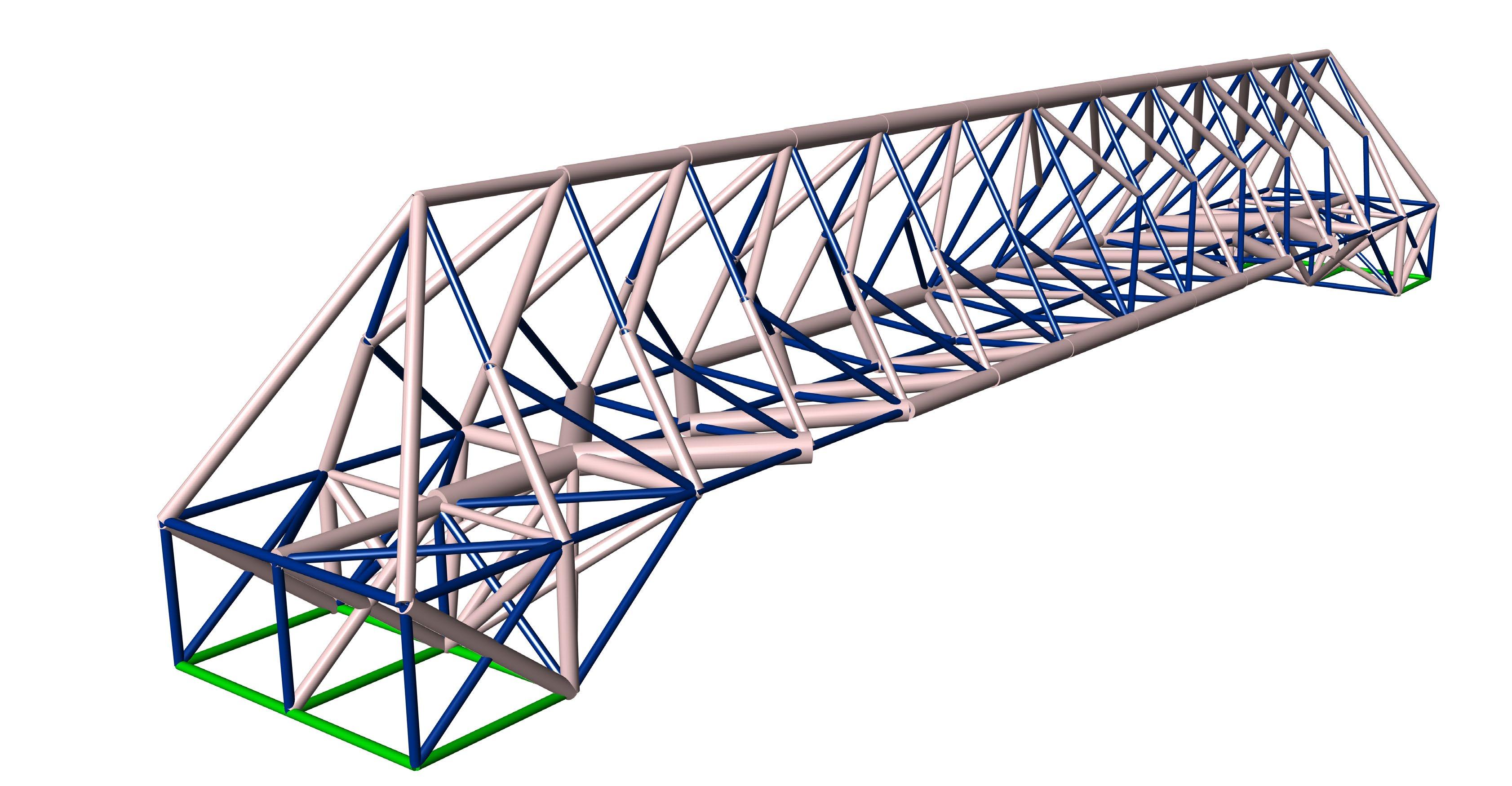
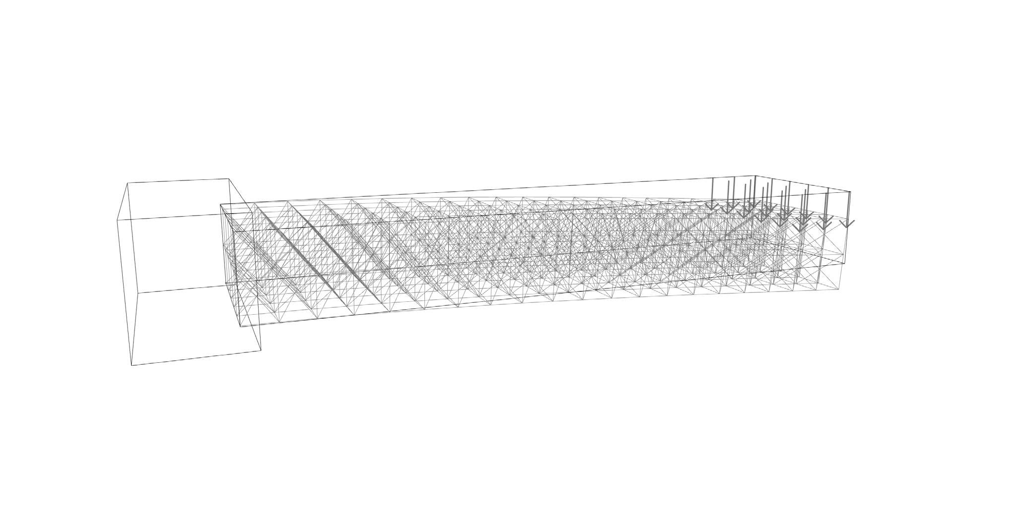
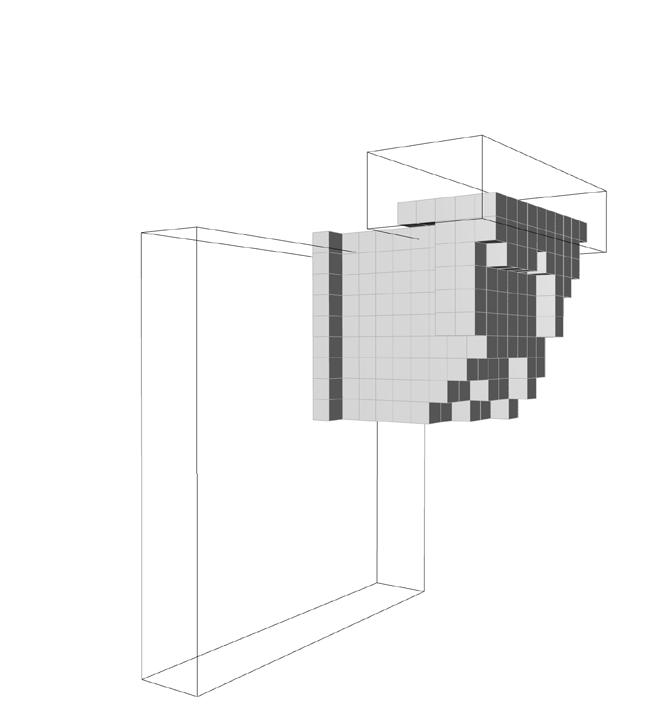
Truss bridge, analyzed by the simulator. The members under compression have been scaled accordingly.
A truss is a structural framework composed of triangular units connected at their vertices, typically used to support roofs, bridges, and other expanses. These triangular shapes confer stability and distribute loads efficiently, enabling trusses to span large distances without internal supports. In trusses, we assume that all forces are applied to the nodes, therefore all beams only endure axial forces, simplifying the analysis and design of these structures.
Mass-Spring-Damper
Mass-spring-damper systems are fundamental models in physics and engineering used to simulate the dynamic behavior of structures subjected to various forces. These models consist of three main components: masses, springs, and dampers.
Mass (m): This represents the object’s inertia, which resists changes in its motion. In a typical mass-spring-damper system, the mass moves in response to forces exerted by the spring and damper.
Spring (k): The spring provides a restoring force that is proportional to the displacement of the mass from its equilibrium position. This force can be described by Hooke’s Law:
FS = -k.x
where FS is the spring force, k is the spring constant, and x is the displacement from the equilibrium position.
Damper (c): The damper opposes the velocity of the mass, modeling resistance or friction that dissipates energy. The damping force is usually proportional to the velocity:
FD = -c.v
where FD is the damping force, c is the damping coefficient, and v is the velocity of the mass.
The dynamic behavior of the mass-spring-damper system is described by a second-order differential equation that incorporates the forces exerted by the spring and damper:
m.a + c.v + k.x = F(t) Here, a is the acceleration, v is the velocity, x is the displacement, and F(t) is any external force applied to the system.
Due to the fact that beams under axial forces and before the yield point acts like springs, therefore the spring rules apply to them. And we can use these rules in simulations.
private double UpdateConventional(int Step_count){ double free_forces = 0; // update beams, position is input, force is output for (int iterator = 0; iterator < Step_count; iterator++){ for (int i = 0; i < BeamCount; i++){
); // vector from start to end Nodes[Beams[i].StartNode].Force -= vector_force; Nodes[Beams[i].EndNode].Force += vector_force;
}
// add the constant force to some nodes with force for (int i = 0; i < ForcedNodesIndexes.Length; i++)
Nodes[ForcedNodesIndexes[i]].Force += Nodes[ForcedNodesIndexes[i]].ConstantForce; // enforce damper constant to all nodes for (int i = 0; i < NodeCount; i++)
Nodes[i].Force -= Nodes[i].Velocity * DamperConstant; // make nodes with support 0 in force, put them in the ReactionForce for (int i = 0; i < SupportedNodesIndexes.Length; i++){
// sum the free force, only for the last iteration! if (iterator == Step_count - 1) for (int i = 0; i < NodeCount; i++) free_forces += Nodes[i].Force.Len(); // update nodes with the force they receive for (int i = 0; i < NodeCount; i++){
return free_forces; } Code: Conventional Implementation of Truss Simulation, with CPU
GPU vs. CPU
For small trusses, the simple implementation of mass-spring-damper systems is effective. However, for systems with many nodes and beams, this method becomes slow. Given that each update in a node or beam operates independently, the benefits of parallelization are applicable. Although parallel computing is available on any modern CPU, GPUs are superior for tasks requiring parallelization due to their design for handling numerous simple, non-branching computations, typical of computer graphics. Therefore, GPUs are an optimal choice for our tasks, enhancing performance significantly in large-scale truss simulations.
ILGPU
Due to the course curriculum, the project was required to be implemented in C#. The two main libraries for running mathematical computations on GPUs are CUDA and OpenCL, neither of which natively supports the .NET framework. To address this, I used ILGPU, a just-in-time compiler that translates C# code into CUDA or OpenCL. Because of my laptop’s limitations, I only utilized OpenCL. However, ILGPU facilitates easy conversion to CUDA, which is implemented in the project.
Project Architecture
To facilitate inter-component communications in Grasshopper, the project is compiled into an external dynamic library, importable as an assembly into Grasshopper components. The ‘Truss’ class is crucial, allowing users to construct a truss, apply forces, and set support nodes. Two data structures, ‘ProtoBeam’ and ‘ProtoNode’, store preliminary truss data. Once prepared, the user can initiate the ‘Compile’ function to send data to the simulator, and use ‘Update’ and ‘Receive’ functions to run the simulation and access outputs, respectively.
CPU Results
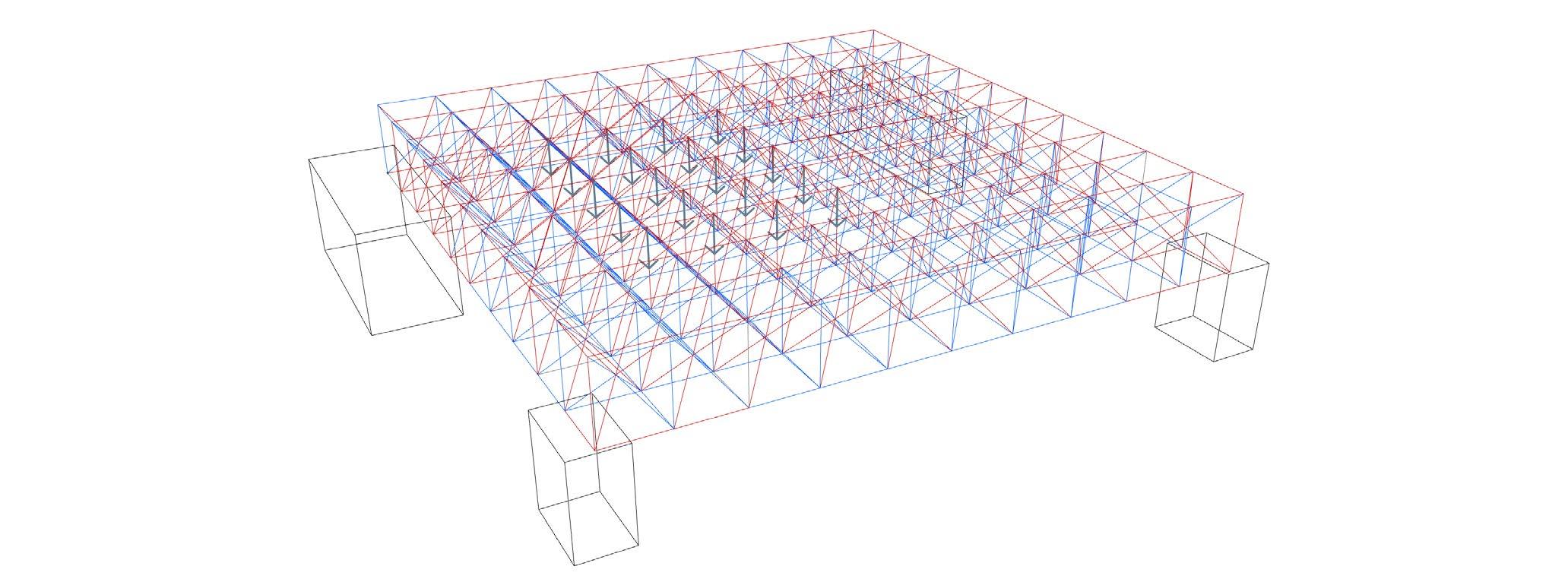
Simulation outputs for simple trusses as a proof of concept for the overall algorithm. All numbers are rounded to zero decimal places.
(red: compressed, blue: in tension, green: zero member)
public class ILGPU_Simulator : ISimulator { // general data: private float DeltaTime, DamperConstant; private int NodeCount, BeamCount, SupportedNodesCount; private bool ContextAllocated = false;
// compiled data: this things are on the GPU, and then they will be copied to the compiled part Context context; Accelerator device; internal MemoryBuffer1D<Node, Stride1D Dense> Nodes; internal MemoryBuffer1D<Beam, Stride1D Dense> Beams; internal MemoryBuffer1D<Triple, Stride1D Dense> ForceOutputsFromBeams; internal MemoryBuffer1D<int, Stride1D.Dense> SupportedNodesIndexes; // kernel functions: Action<Index1D, ArrayView<Beam>, ArrayView<Node>, ArrayView<Triple>> Lk_UpdateBeam; Action<Index1D, ArrayView<Node>, ArrayView<Triple>, float> Lk_UpdateNodeForcesAndDamper; Action<Index1D, ArrayView<Node>, ArrayView<int>> Lk_UpdateSupportNodes; Action<Index1D, ArrayView<Node>, float> Lk_UpdateNodes;
Code: Members of ILGPU implementation of ISimulator
GPU Results
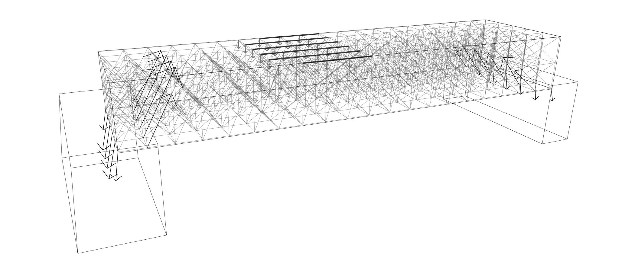
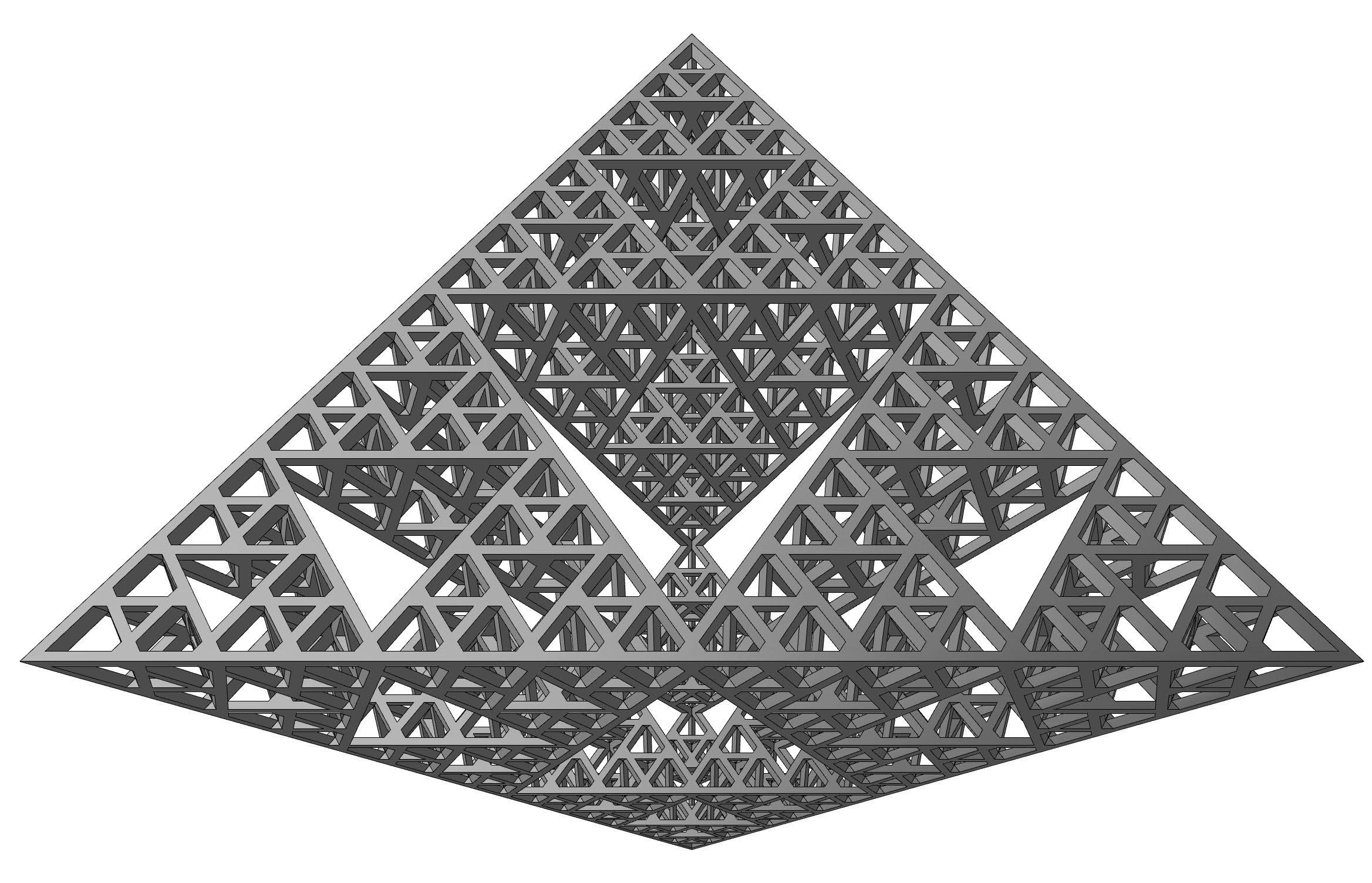
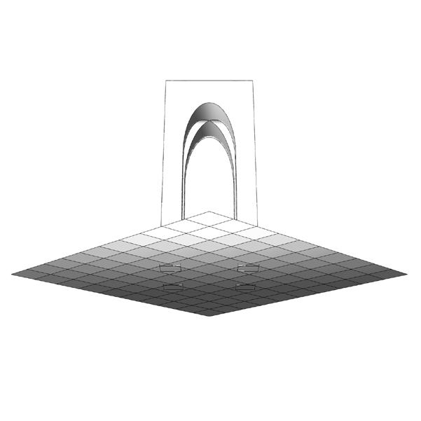
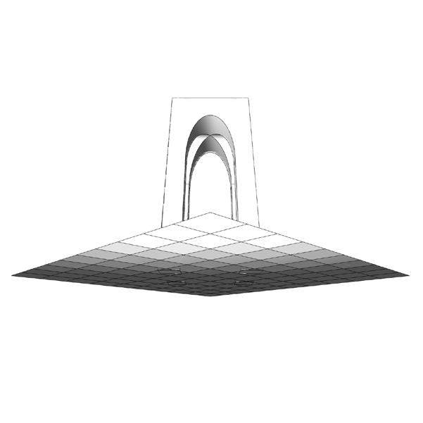
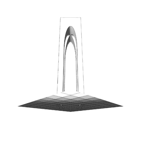
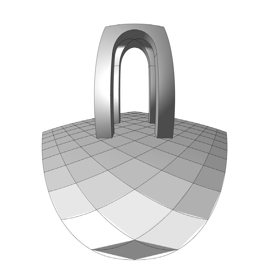
Some examples of massive space frames. This computations are only available with the power of GPU. They also resemble beams and roofs. That shows the potentials in other branches of structural simulation.
Benchmarking
The benchmarking results for a 3D space frame are presented in Table 1. For smaller structures, the CPU implementation is faster due to lower overhead. However, as the structure size increases, the GPU implementation becomes quicker, surpassing even the parallelized CPU performance. The ‘x’, ‘y’, and ‘z’ in the table indicate the number of unit cells in the space frame. Additionally, as you can see, the laptop I used for these tests has a relatively high-performance CPU with a basic GPU. Despite the advantage of the CPU in my system, the basic integrated GPU can easily outperform it.
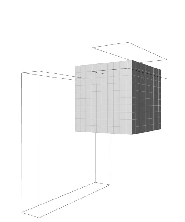
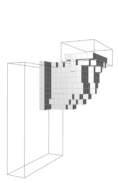
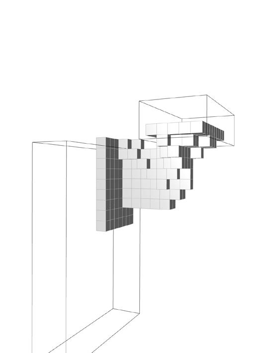
With the tools on our hand, we can explore new potentials. In this experiment, I tried a form of Topological Optimization: In each step, the element with the least force applied on will be eliminated.(Below)
Lk_UpdateSupportNodes(SupportedNodesCount, Nodes.View, SupportedNodesIndexes.View); //device.Synchronize(); // next phases: sum the free force and output it
Code: Implementations of kernels. Each kernel encapsulate one phase of update that can run in parallel
Perspectives Hands-on Tool for Experimenting
with Two-Point, Three-Point, and Fisheye Perspectives
Personal Project: December 2020 (in ghPython, re-written in C# on July 2024)
Abstract
Despite the benefits of new computer-based presentation techniques, the hands-on nature of perspective drawings is sometimes lost in the digital world. The aesthetics of hand drawings, the clear differentiation between an image and the idea of a building, and the use of perspective distortions to accentuate architectural elements are some of the lost benefits. Therefore, I thought we needed a tool to reintegrate this technique into the realm of computer drawings.
In this personal project, I created a tool to convert Rhino 3D models into perspective drawings using Grasshopper and Python, and later C#. For this project, I implemented three techniques of perspective projection: two-point, three-point, and five-point perspectives, each with different approaches. Later, I used these tools in my personal and professional illustrations.
Source Code on GitHub: github.com/PeHaash/PerspectiveProjection
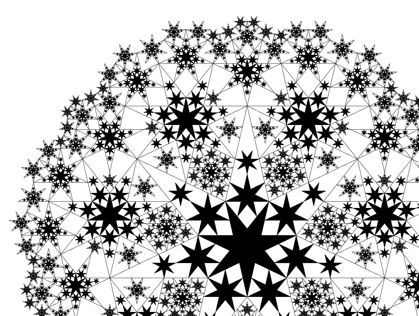
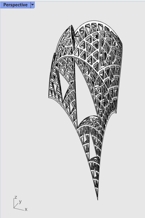
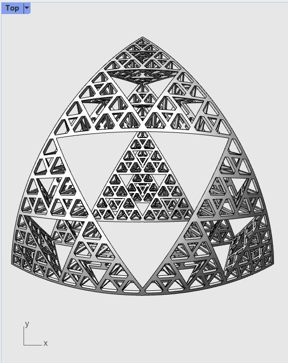
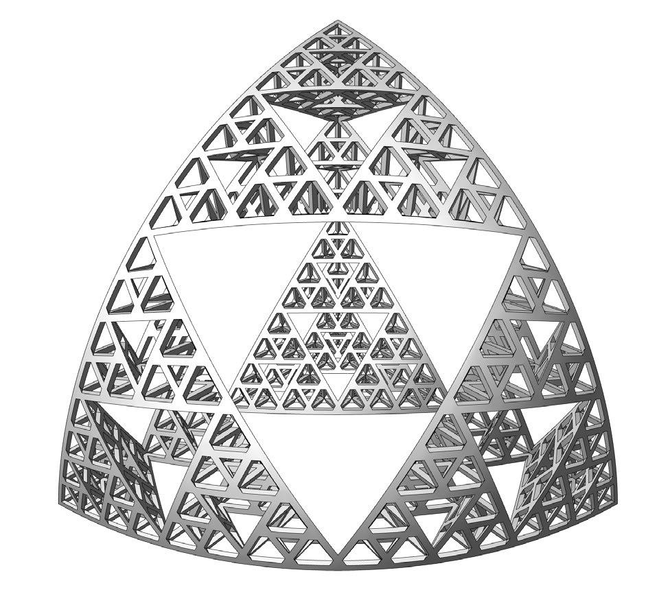
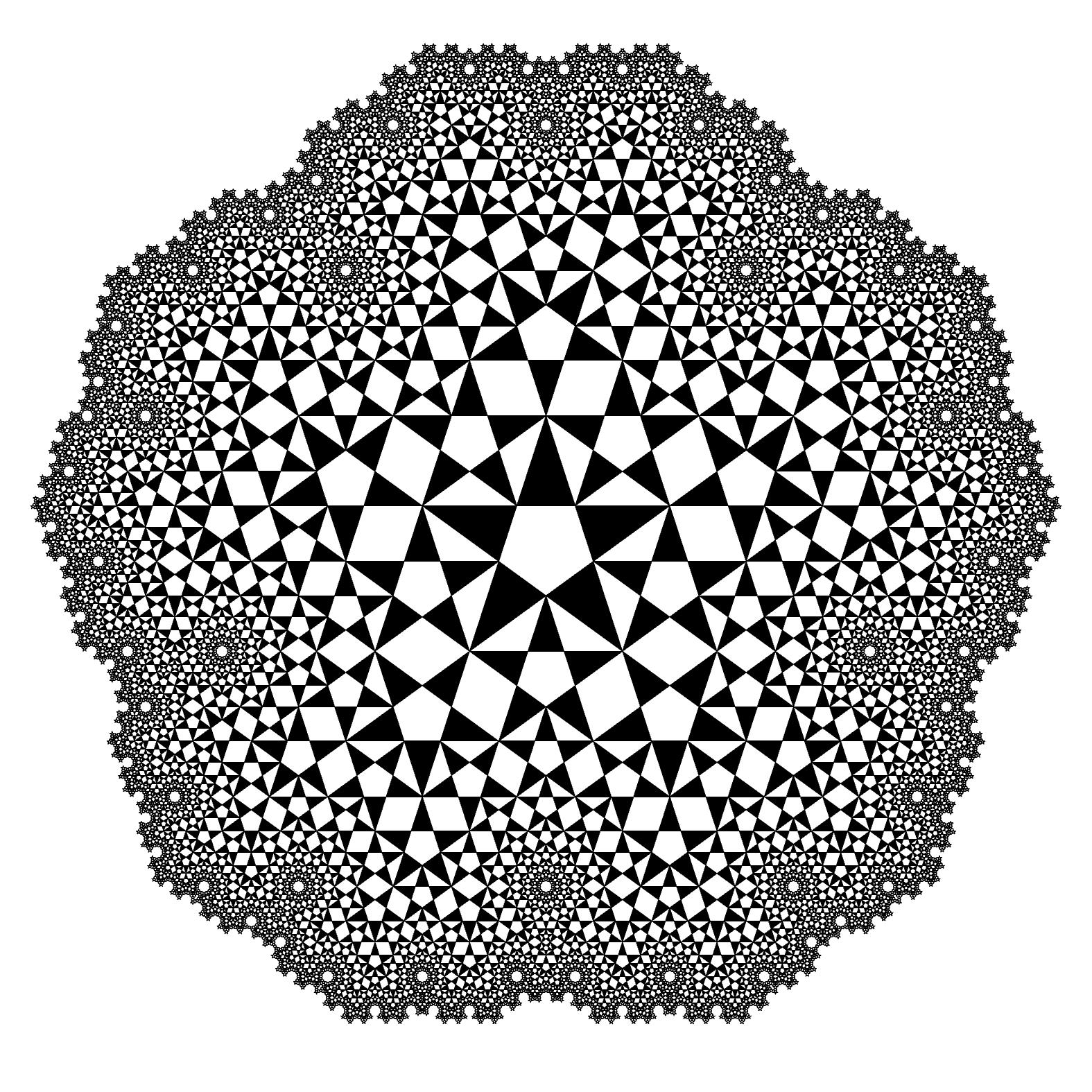
Image: Sierpiński Pyramid, generated with the Two-Point Perspective tool. Screenshot from Rhino.
Perspective
Linear perspective is a method of representing threedimensional objects on a flat surface, emulating what can be seen by the eye. In perspective drawing, distant objects appear smaller, and parallel lines seem to converge at an infinite distance, known as vanishing points. Different types of perspective representations are categorized by their number of vanishing points.
One-Point Perspective: This type uses a single vanishing point on the horizon line. It is commonly used for compositions where objects are directly facing the viewer, such as in straight roads, hallways, or railway tracks.
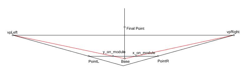
Two-Point Perspective: This type uses two vanishing points on the horizon line. It is often used for drawing buildings or objects at an angle, showing two sides receding into the distance. The drawing techniques for one-point and two-point perspectives are essentially the same, and one image can have both these vanishing points simultaniously.
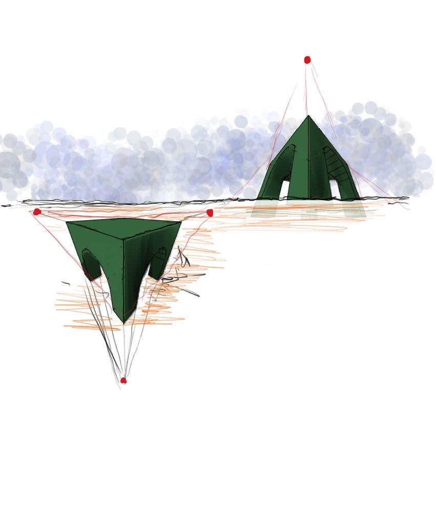
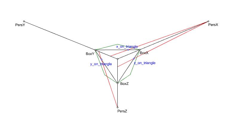
Three-Point Perspective: This type involves three vanishing points, two on the horizon line and one either above or below. It is typically used for dramatic or dynamic compositions, such as looking up at a tall building or down from a high viewpoint.
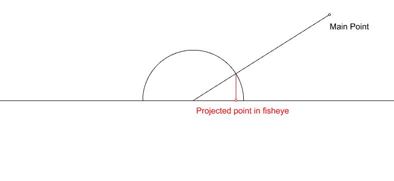
Five-Point Perspective: This type, also known as fisheye perspective, uses five vanishing points. It creates a curved, panoramic view, often used for artistic and abstract representations, capturing a wide field of view in a single image.
Implementation
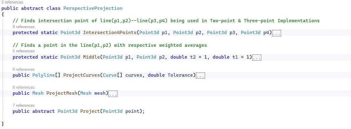
Using a pre-compiled library in the form of an assembly file can increase the performance and reusability of the code. A base class contains shared functions for projecting meshes and curves to the perspective, and a Project() function that encompasses the logic of transforming a point to the respective perspective views. This function is implemented in the derived classes for two-point, three-point, and fisheye perspectives.
Overlaps
In the final projection, some parts of the geometry may overlap and obscure underlying parts. Identifying these parts is not easy and requires intensive computations. Therefore, I circumvented this issue by utilizing the built-in capabilities of Rhino/ Grasshopper. In my project, the 2D output is projected so that the X and Y coordinates represent the projected coordinates, and Z is the negative of the perceived distance of each point. This results in a distorted shape, but when using the top view in Rhino, the final output can be seen correctly.
Implementations:
For each projection, we first need to convert the world coordinates we receive to perspective coordinates. In Two-Point and Fisheye perspectives, this is done using the ‘RemapToPlaneSpace’ function. For Three-Point perspective, we use matrix multiplication with the stored inverse matrix. After that, each Project function applies the basic principles of hand-drawn perspective drawings, such as drawing lines to the vanishing points and finding the intersections.
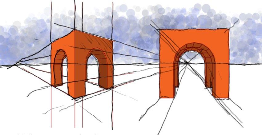
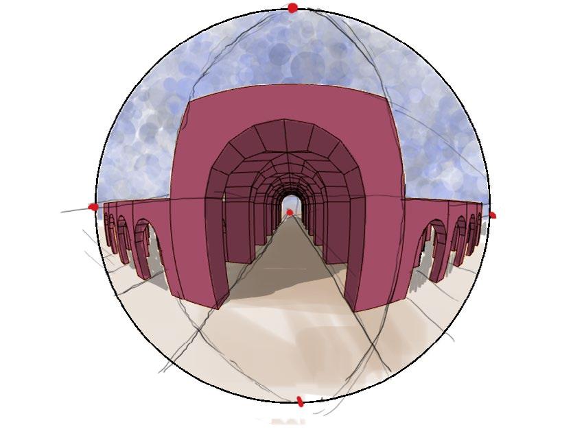
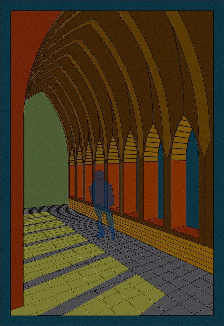
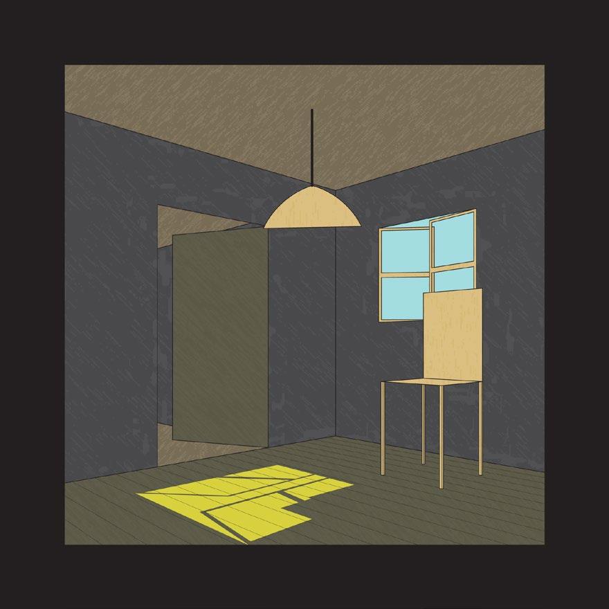
On this page, you can see some examples of each perspective system. On the left, a single scene is represented with different parameter tunings for each image, causing distortions and accentuations in various aspects of the depicted building. All images are screenshots from Rhino. On the right, there are more examples of drawings using the two-point system. Colours are added to the images in Illustrator, showcasing its potential as an expressive tool not only in architecture but also in illustrations.
Two-point Perspective
Three-point Perspective
Fisheye Perspective
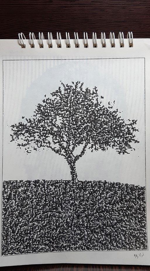
Illustrations
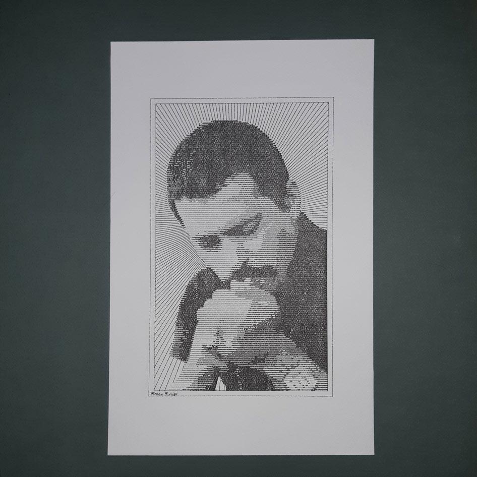
CNC Drawings Converting Digital Images into Paintings with Pen Plotter & Laser Cutter
Personal Project: October 2019 - April 2021
Introduction
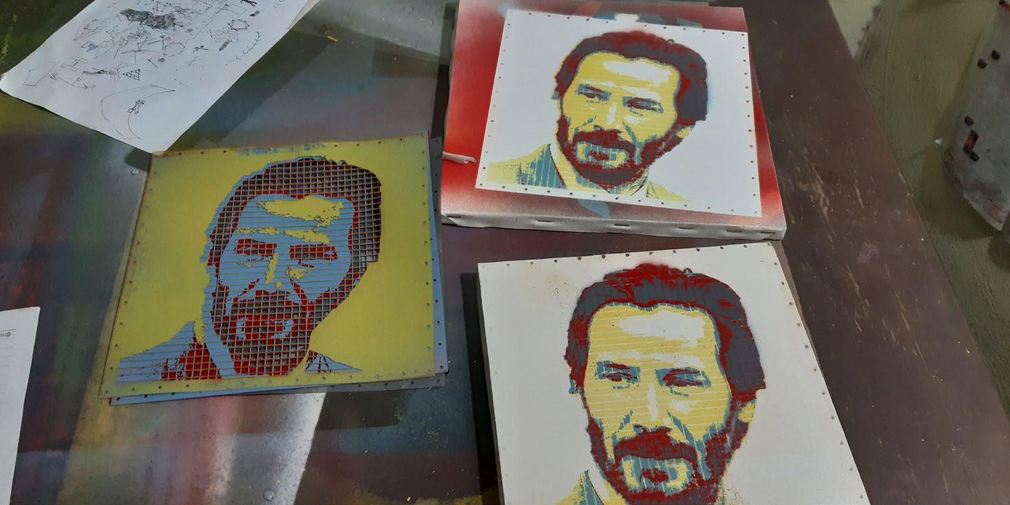
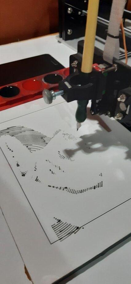
After completing my undergraduate studies and during the Covid-19 lockdown, I found time to focus on one of my curiosities: generating drawings with CNC-driven machines and other methods of converting digital pictures into paintings. I purchased a pen plotter and, after understanding the machine’s GCODE, I began writing programs and implementing various algorithms to convert images into CNC drawing instructions using different techniques. In the following pages, you will see examples of my experiments with CNC laser cutting, pen plotting, digitally lasered stencils, and watercolor drawings created with pen plotters. Ultimately, I started a small side hustle that converts people’s pictures into tangible, unique pieces of art.
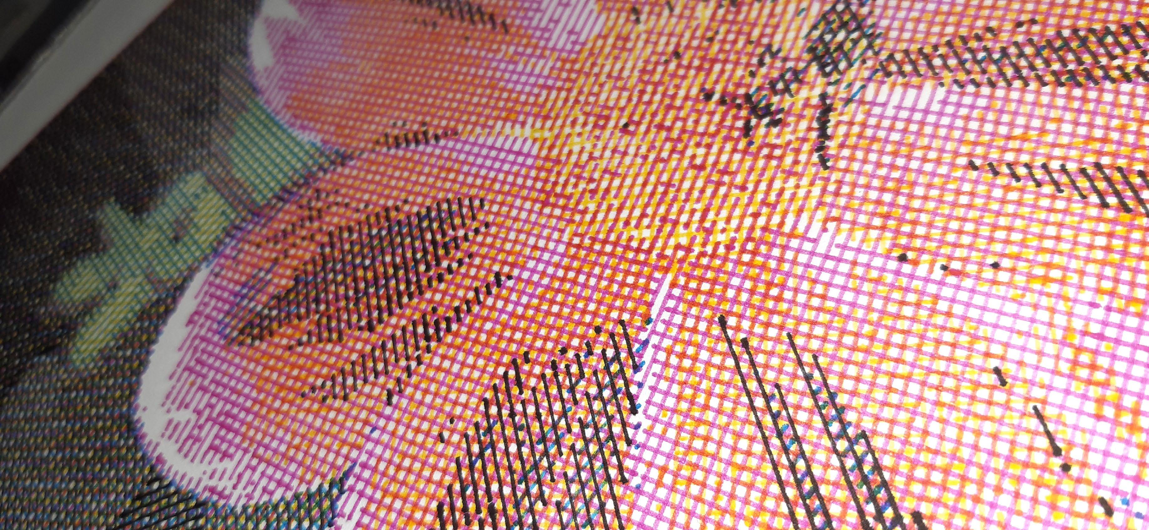
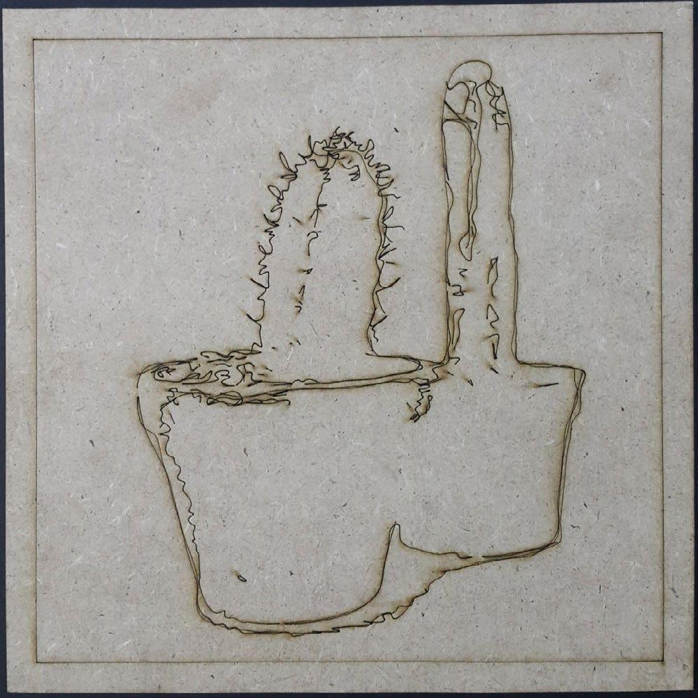
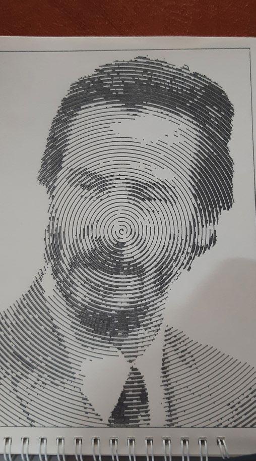
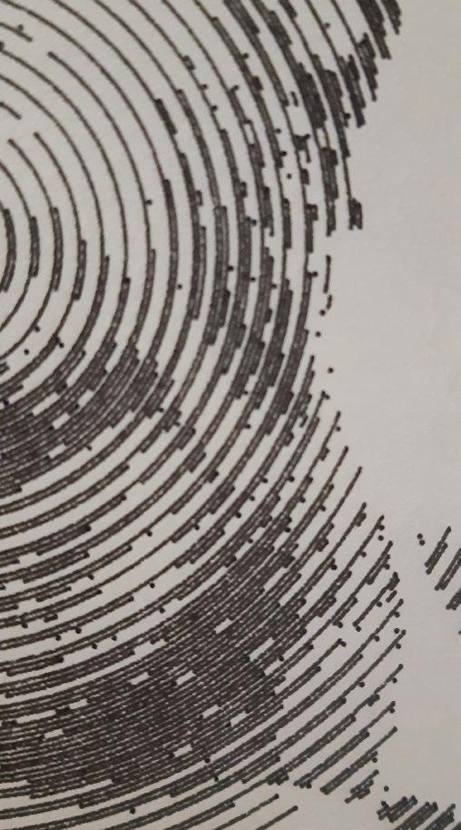
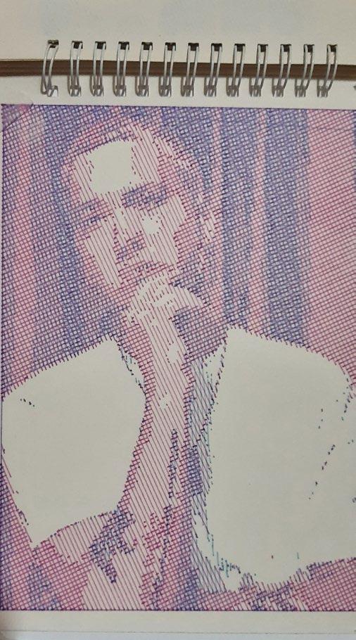
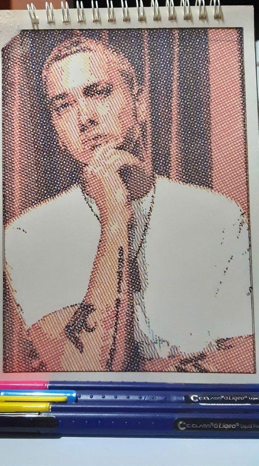
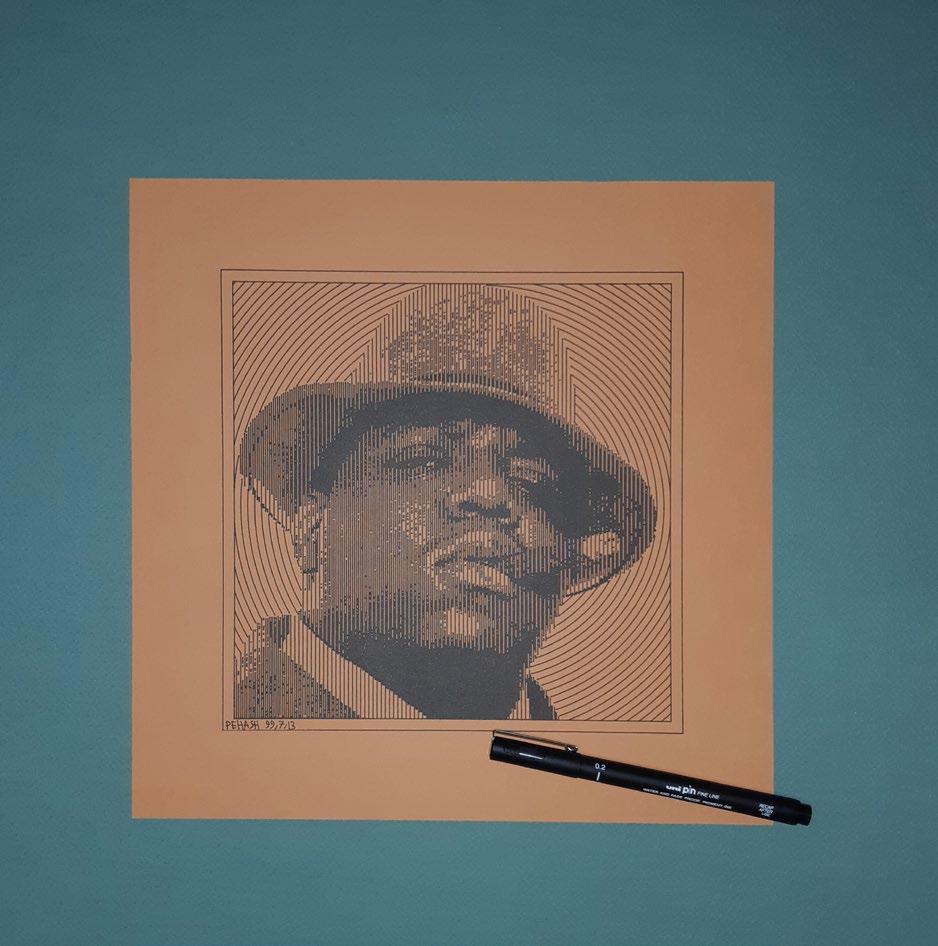
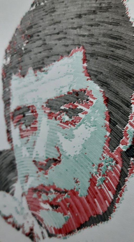
Image: Details of one of my drawings, with four colour (CMYK) using pen plotter
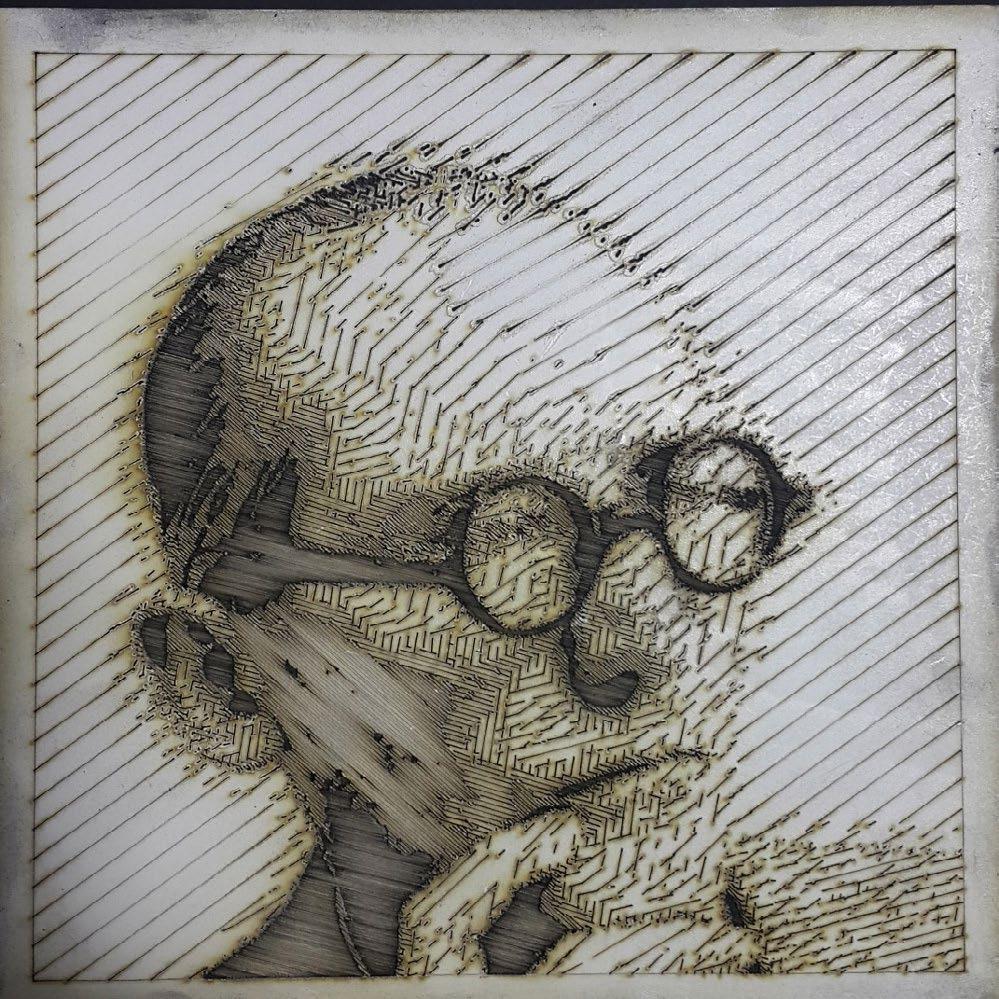
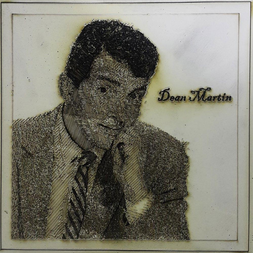
Laser Cut Engraving
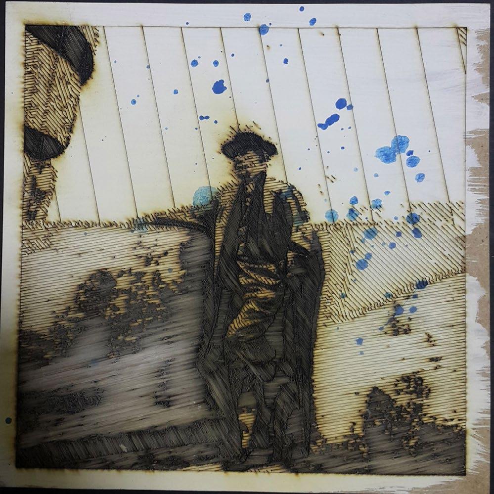
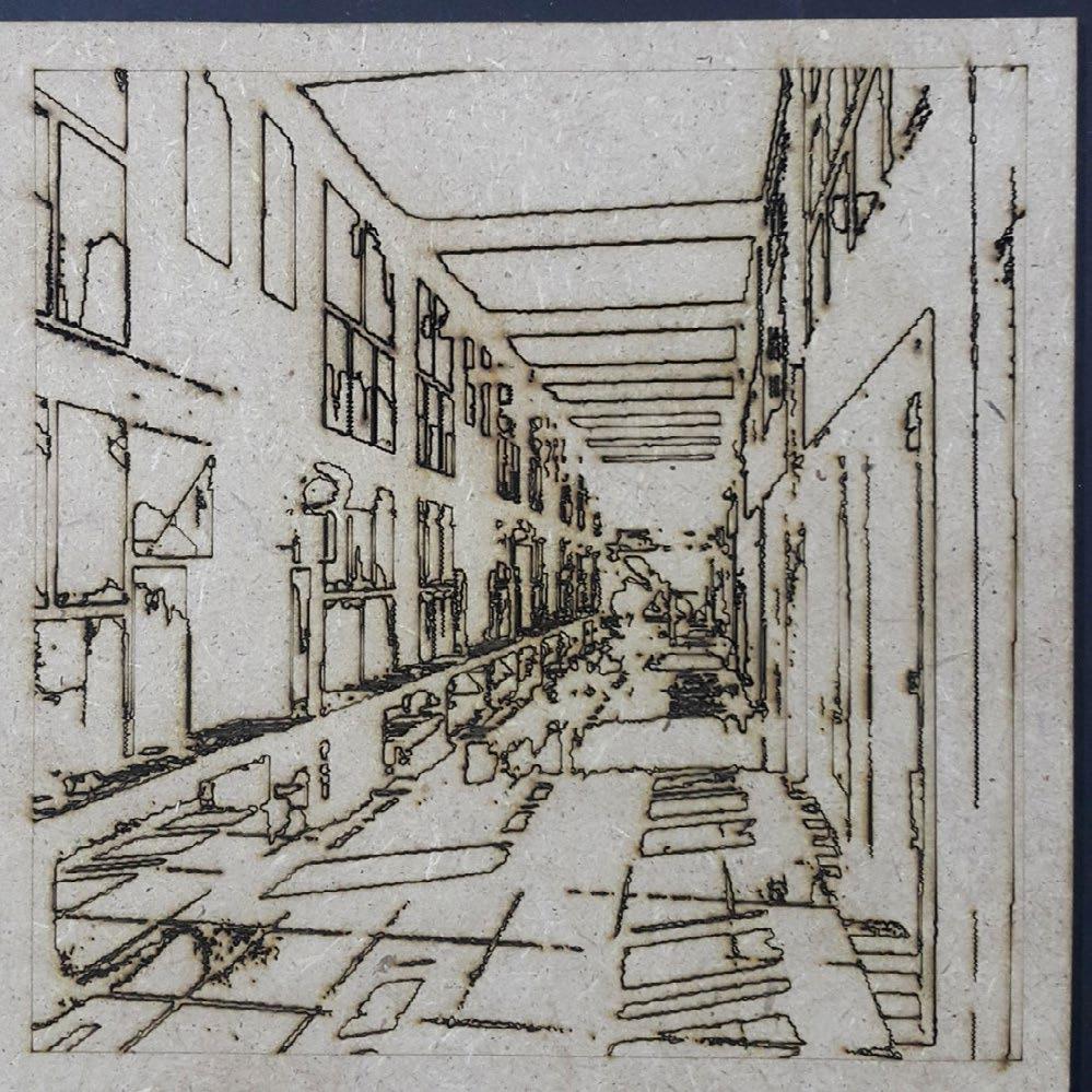
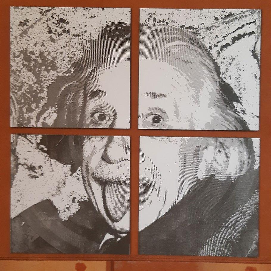
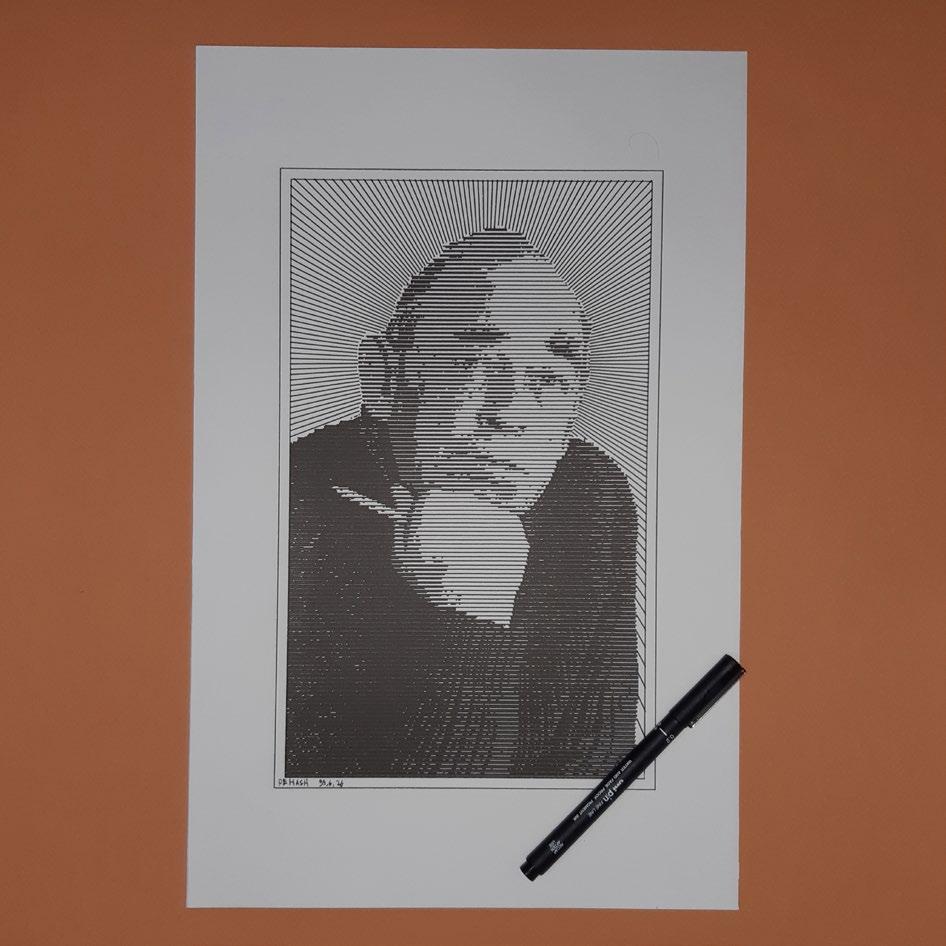
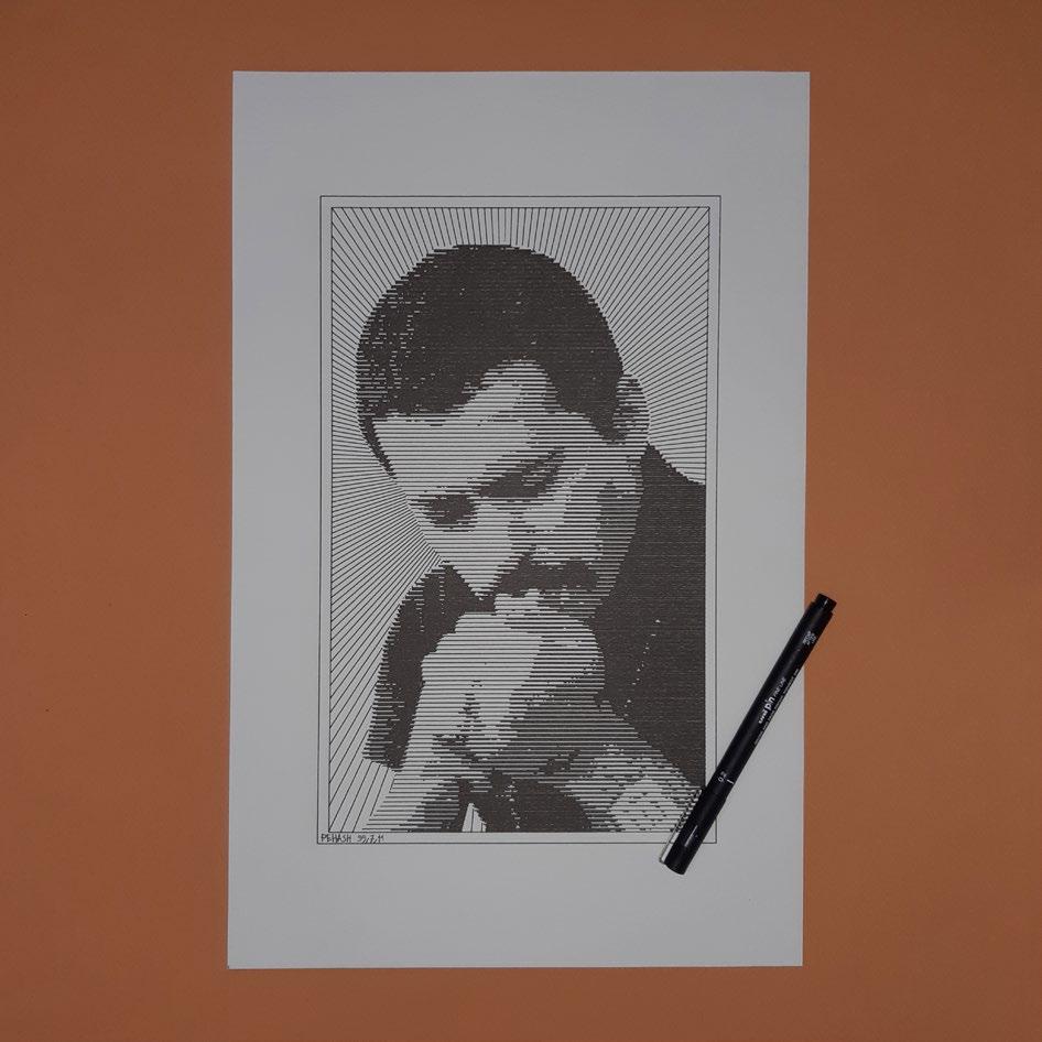
When I was working as a laser cutter operator, I had plenty of free time that I used to experiment with engraving wood as a drawing medium. I wrote some scripts in the Processing programming language that received an image, posterized it based on the brightness of each pixel, and hatched each shade of darkness in a random direction with predefined intensity. This was a means to draw images in a unique and novel manner. I also conducted some research on implementing edge detection algorithms.
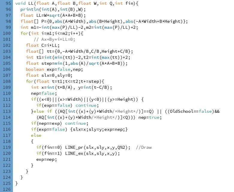
The input of the Processing script is an image, and the output is a list of lines, readable in Rhino/ Grasshopper. The laser cutter machine received a .dxf file exported from Rhino.
Code: Main part of the hatching algorithm. unfortunately, due to being a personal project, I never tried to extensively document the code for presentation.
Pen Plotter: Hatches
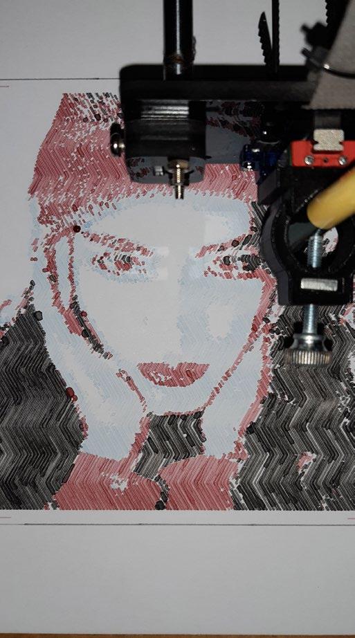
With the promising results of my work and after graduating from university, I decided to purchase a pen plotter so I could develop these ideas further. Initially, the script remained the same, with the addition that it also exported *.gcode files, bypassing the need for .dxf conversion. However, I later migrated the code to ghPython to take advantage of Rhino API’s extensive libraries and its interactive environment. Additionally, using a pen provided me with more artistic freedom in colouring, as well as new programming challenges in generating multi-colour outputs. Although the basic structure of my pen plotter made calibration between different colours difficult, I managed to create some four-colour drawings using Cyan, Magenta, Yellow, and Black pens.
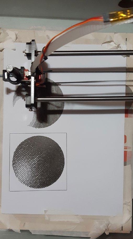
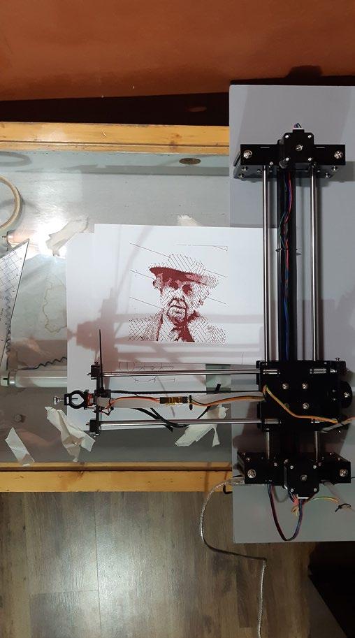
Pen Plotter Set-up
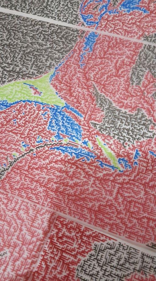
Example of Drawings, with details
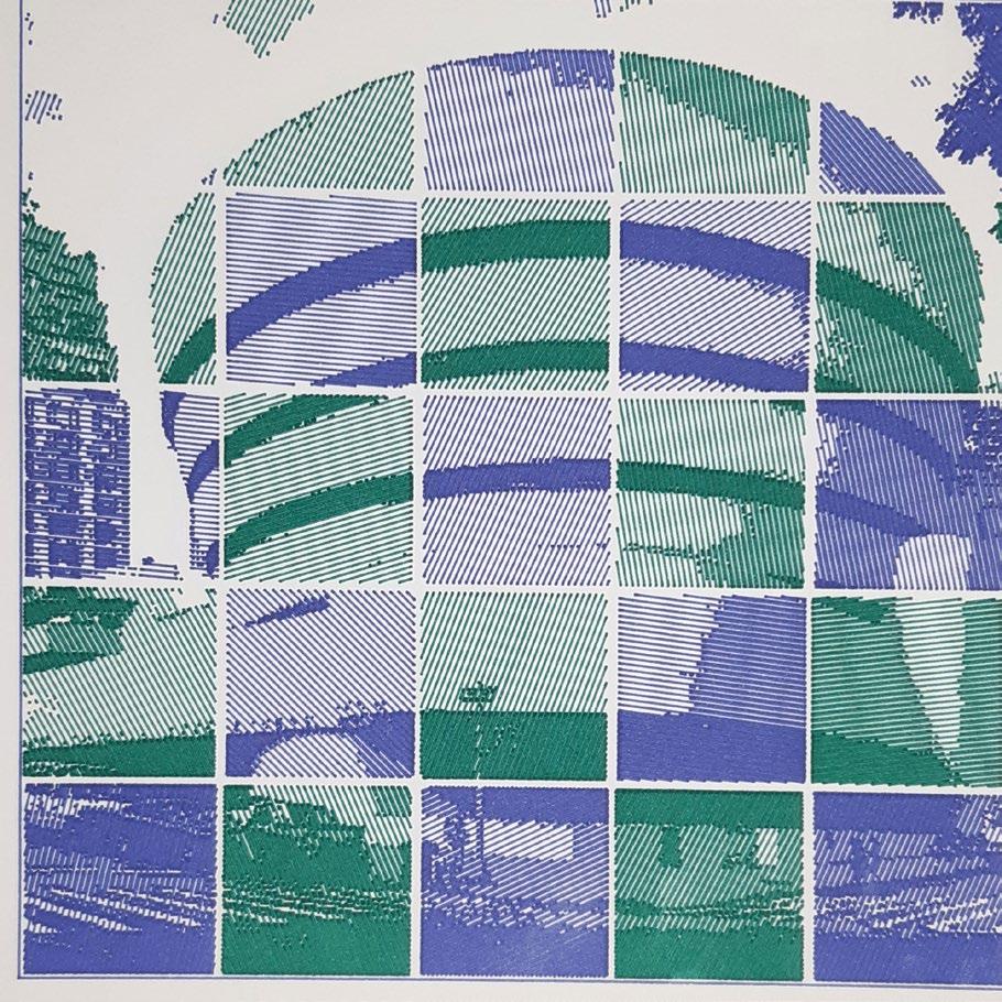
Building drawings, with two colours
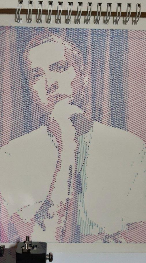
Multi-colour drawings, each level of adding one colour (C, M, Y, K in order)
Multi-frame drawing, to overcome small size of the pen plotter (approx. 20*30 cm)
Pen Plotter: Hatches
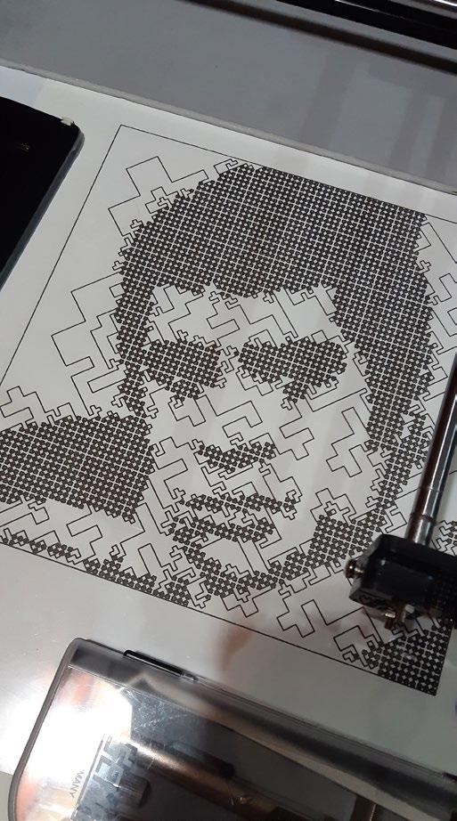
Stencils
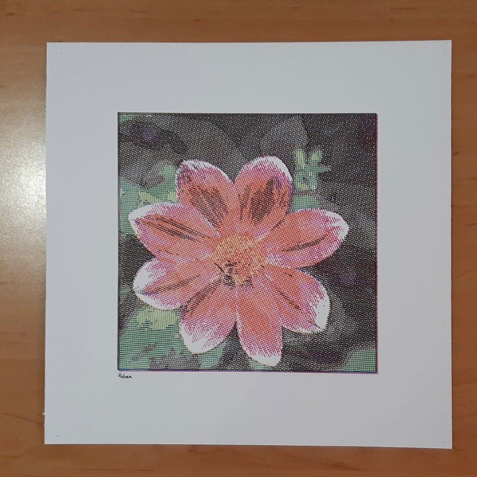
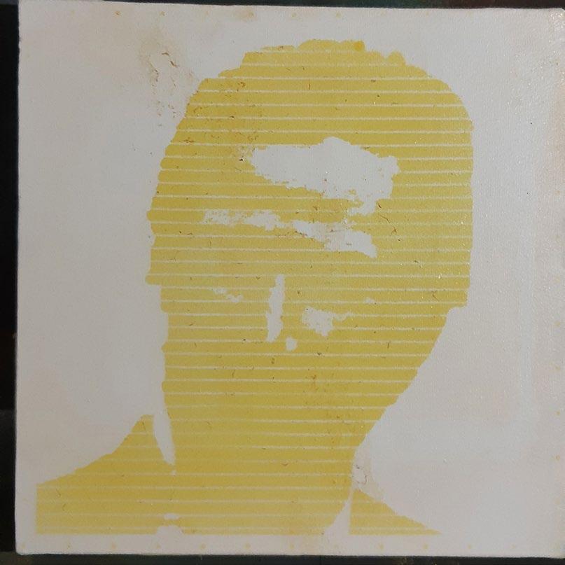
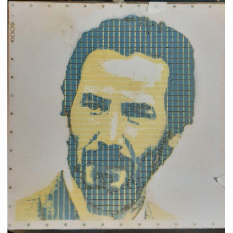
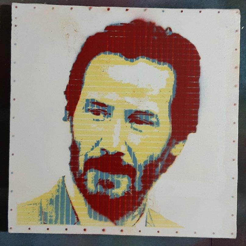
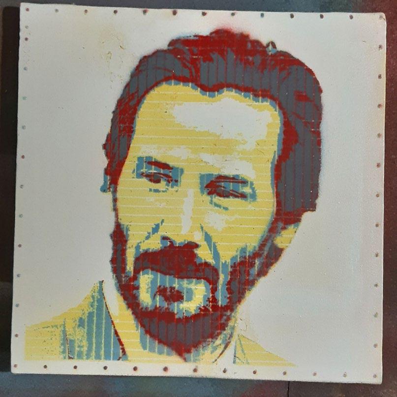
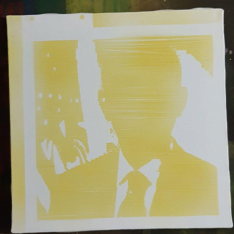
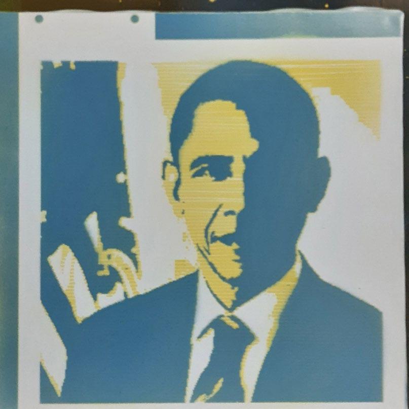
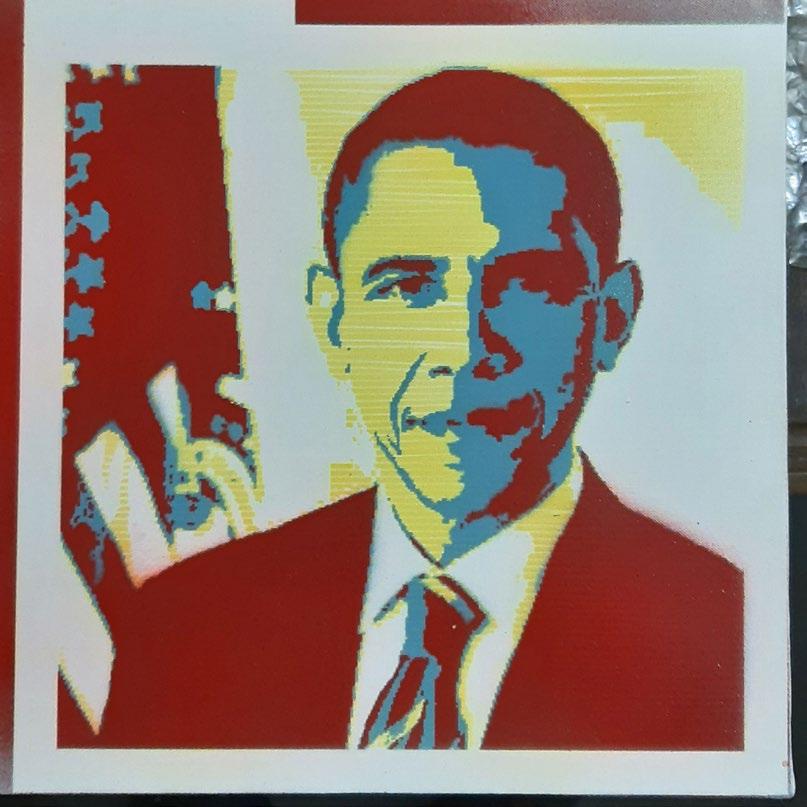
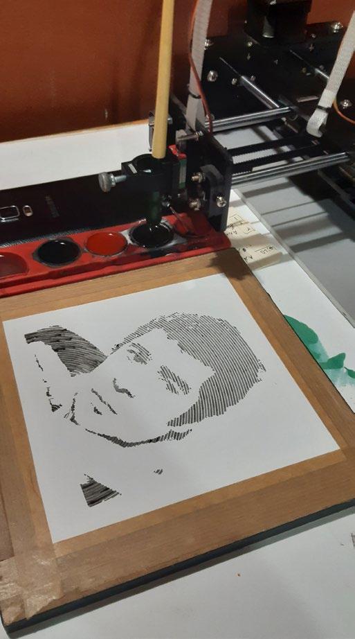
Another drawing method I tested was producing stencils from images. These stencils, computationally created and cut with a CNC laser cutter, can be used to generate the same drawing multiple times. The process involved dividing colours (similar to the previous method) and then creating a stencil for each colour. The main challenge was keeping the stencil intact, as there might be “islands” of covered parts within each colour, necessitating bridges to hold them together. The method I used involves placing an overall grid over each stencil to minimise the unreachable islands and to add texture to the entire drawing. The stencils are made from PVC binding covers, providing remarkable endurance for reusability and sufficient thinness to produce highquality details in the drawings.
Steps of applying colour to the canvas with stencils. You can see grid-like patterns of bridges, as well as controlling points around the image
Other Experiments with Pen Plotter
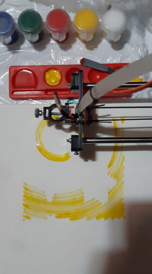
Draiwing with water colour: it had many unique challenges such as the need to refill the pen, and inherent unpredictibality of water based pigments
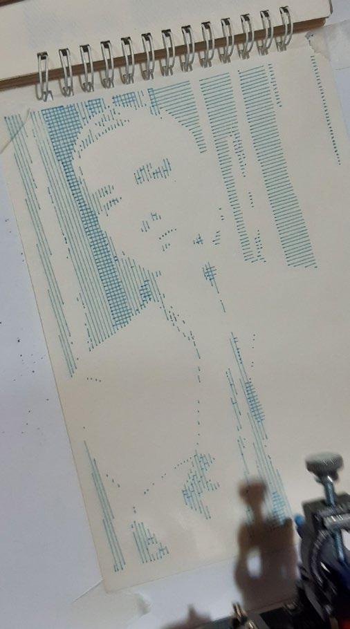
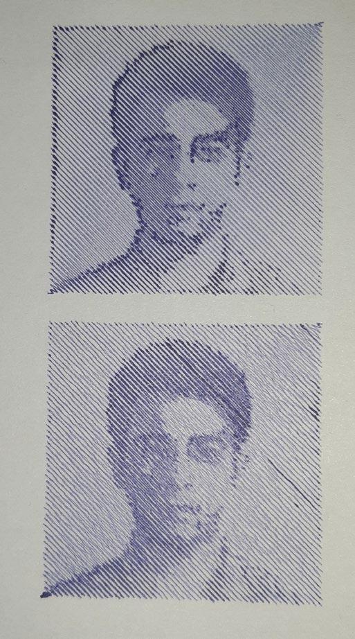
Single Line Drawings with Different Algorithms:
Due to the high wear and tear on the servo motors used in the pen plotter to lift and place the pen on the paper, I experimented with different methods to minimise its movement. Consequently, I explored various ideas for creating drawings with a single line. These methods included using semifractal drawings, BFS and DFS graph traversal algorithms, and natural hatch patterns typical of BIC pens.
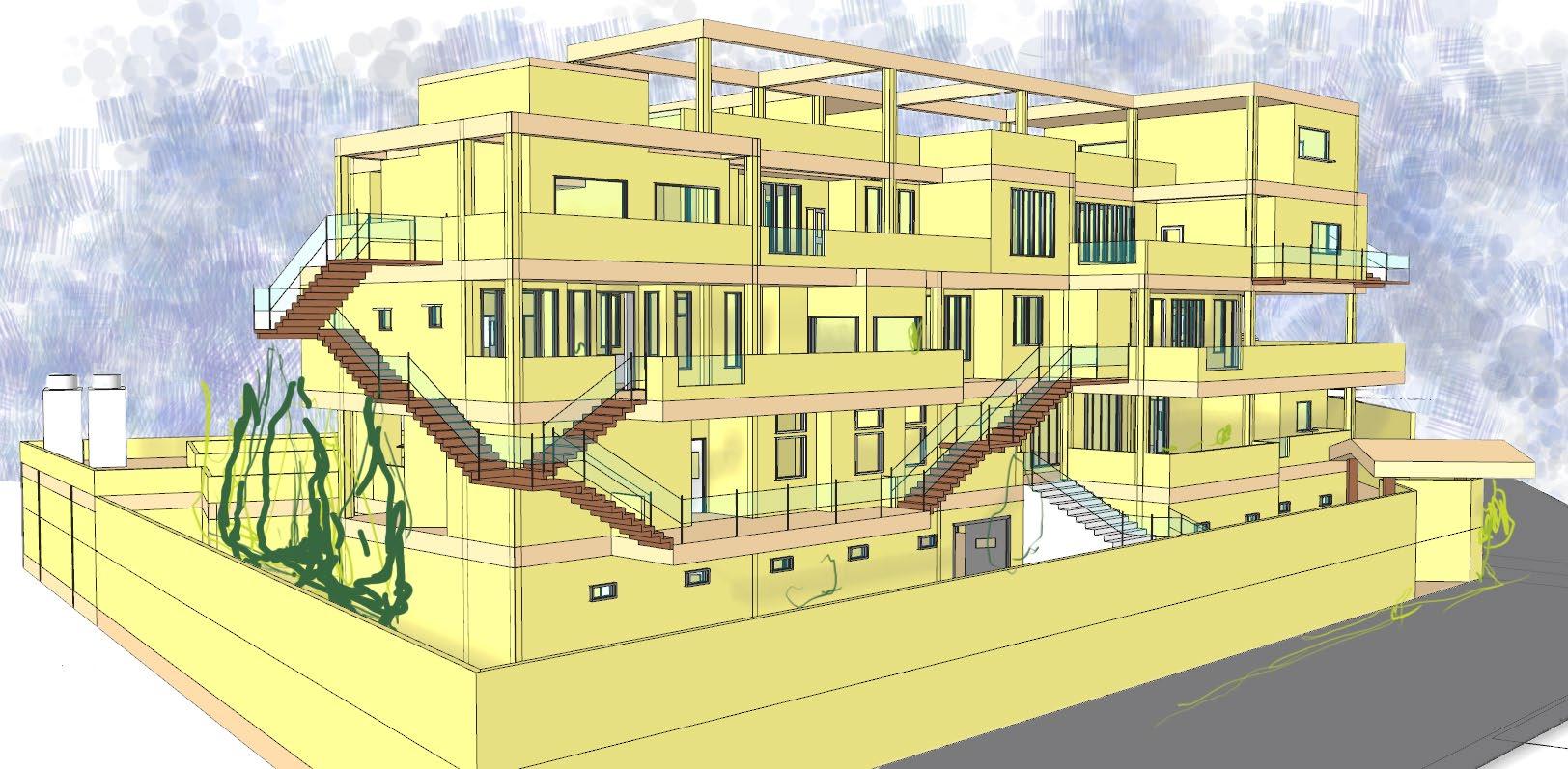
Condominium for Remote workers A Design With Pattern Language
Final Project of B.Arch, September 2019
Supervisor: Hamed Mazaherian (mazaheri@ut.ac.ir)
Abstract
Even before the COVID-19 pandemic, telecommuting was a trend in business. Remote work is beneficial for the environment, as well as the family connections of the employees. Still, with all of the advantages of telecommuting, there are significant drawbacks.
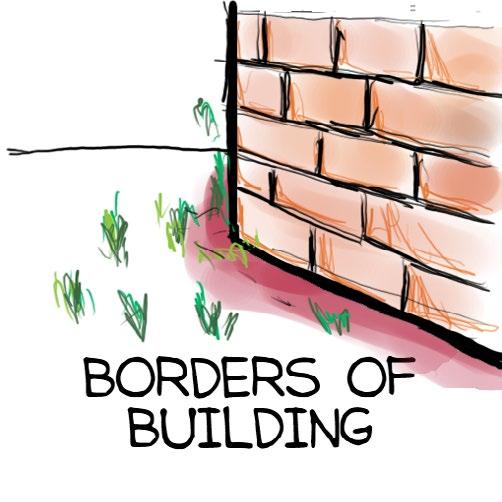
The most crucial disadvantage of telecommuting is that it can blur the border between home (a place for relaxation and peace) and the workplace (a place for stress, tension and productivity)
Therefore, it’s challenging for architects to design a good house that can handle the complexities of remote workers’ work/life balance. I addressed these issues in my project.
Moreover, I implemented pattern language in a full-scale architecture project to test its potential.
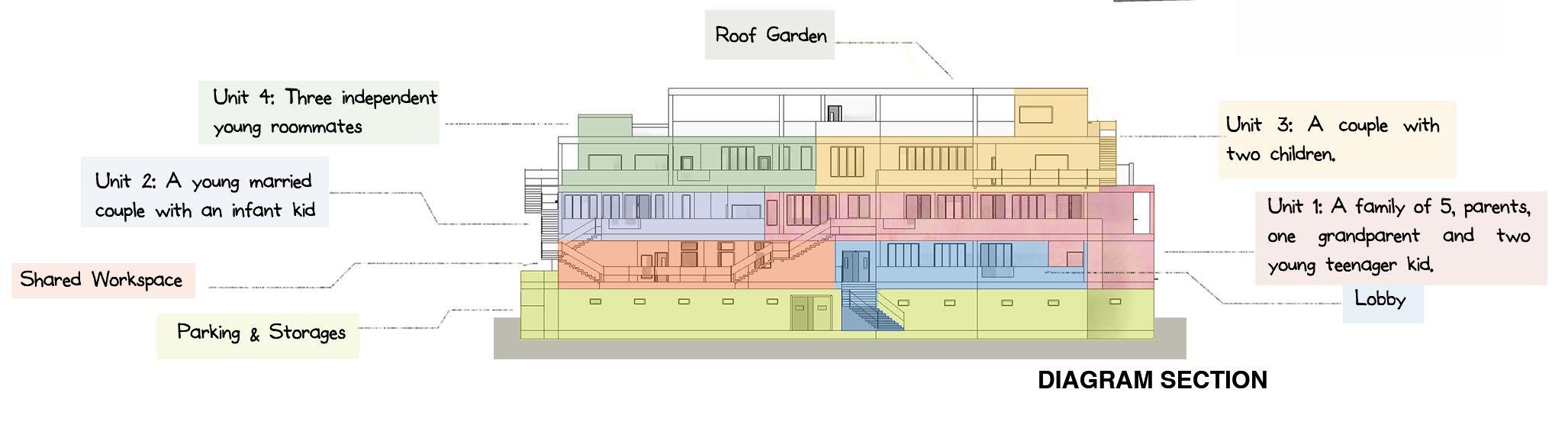
Project Brief
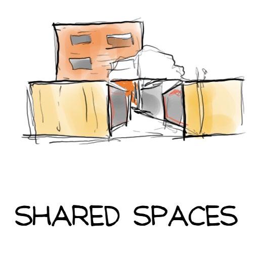
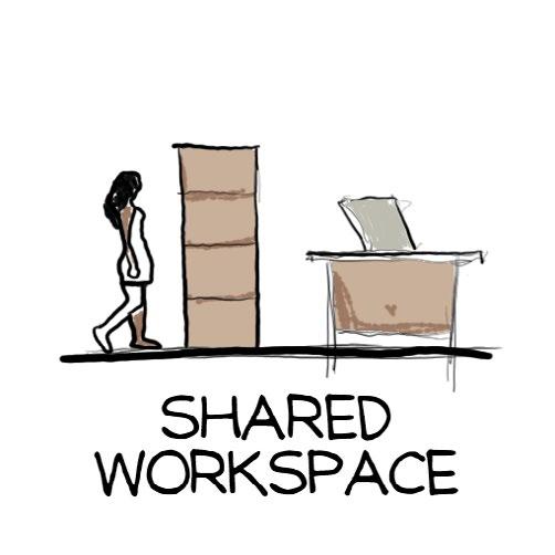
I decided to design a housing unit for four families whose breadwinners are telecommuters. These four families have different characteristics (such as a newlywed couple and a family of four), but all work in the IT industry from their houses. In addition to the four different flats, a shared workspace and other facilities were other parts of the brief.
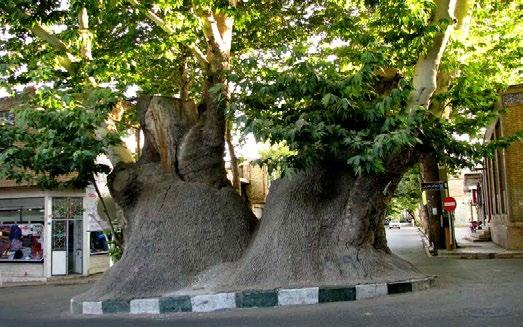
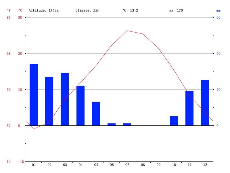
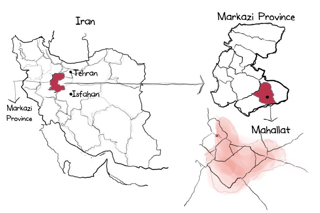
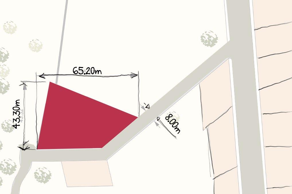
The project’s site is in Mahallat, Markazi province, Iran. Low land prices in Mahallat, its proximity to Tehran and Isfahan (important financial centres), and its mild climate can attract telecommuters to select Mahallat for living. The project site is a small land near the boundary of the city.
Pattern Language
Pattern Language is an organized and coherent set of patterns. Each Pattern is a formal solution to a problem in a context. With a well-designed pattern language, we can design beautiful and functional buildings.
Definition
Pattern Language is an organized and coherent set of patterns. Each Pattern is a formal solution to a problem in a context. With a well-designed pattern language, we can design beautiful and functional buildings.
Benefits
* Shifts design from an unconscious phenomenon into a logical and unambiguous task without compromising its artistic aspects.
* Can be used in different projects without making buildings similar or hurdling creativity.
* Can be shared between different architects.
* Gave us a powerful tool to emulate good design ideas from other architects.
How I Used Pattern
Language
* I use pattern language in this project to test whether it can stand to its promises.
* So, I created a pattern language.
* Due to time constraints, I could only implement some of my patterns in the final project.
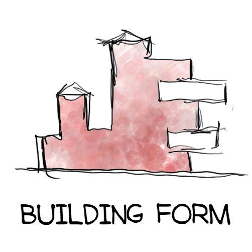
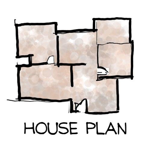
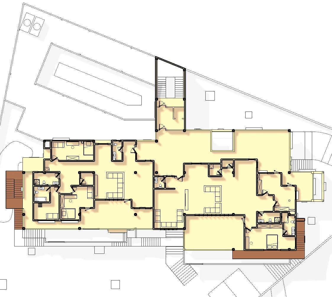
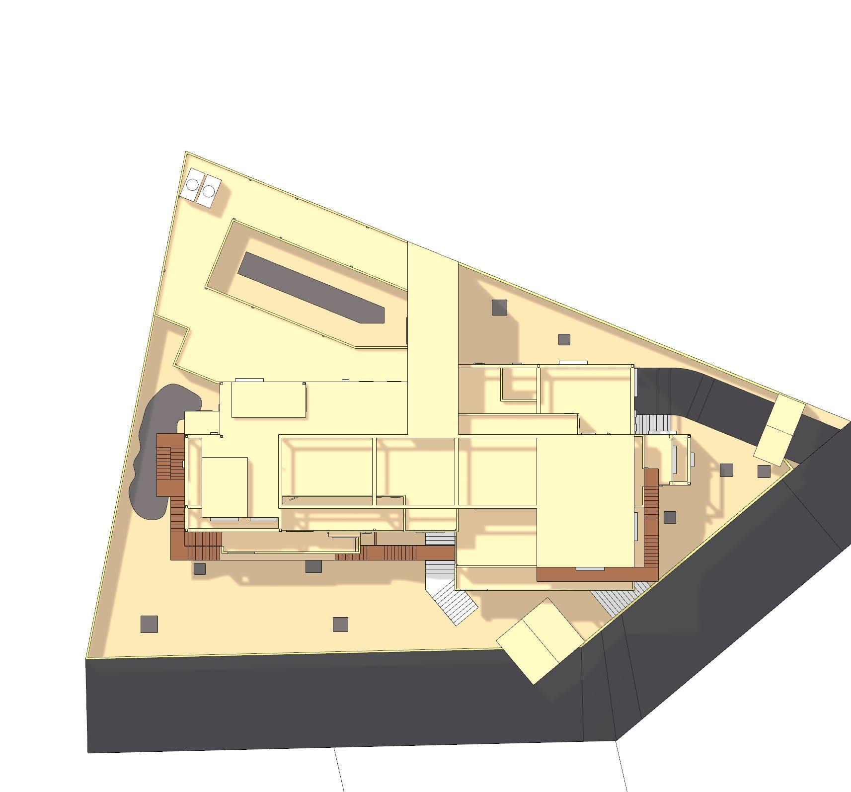
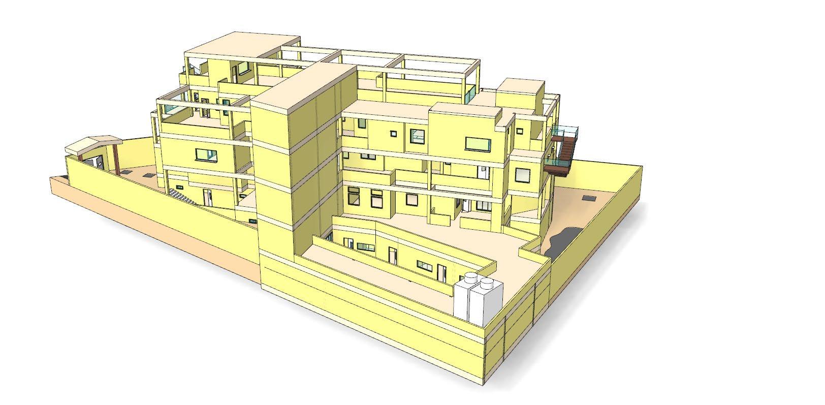
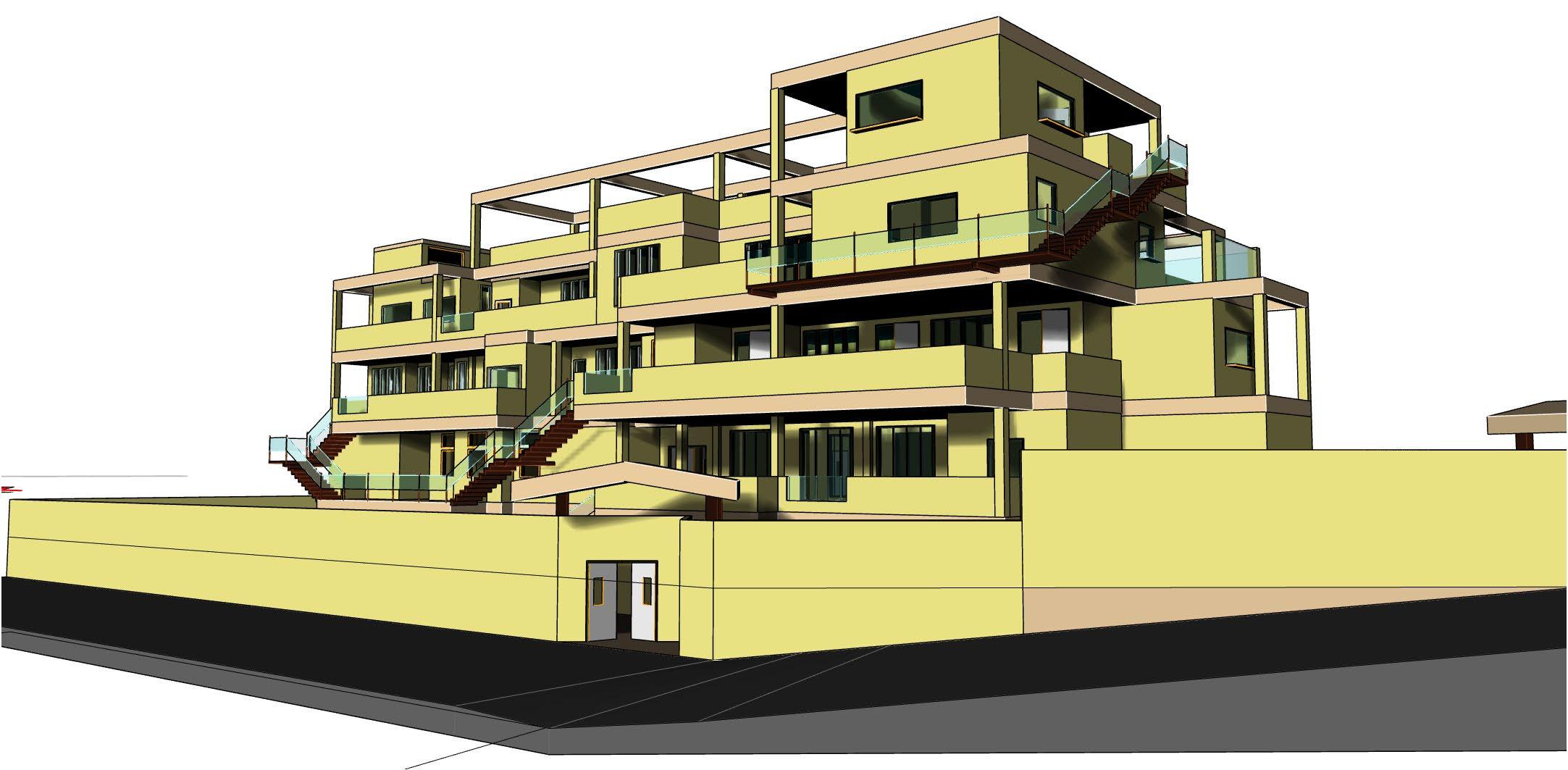
* I focused on fundamental patterns, which can be seen in the plan and final form.
* Small-scale patterns can be added to the project later.
Example of Patterns
Context: Houses of urban middle-class families.
Problem: A family wants to hang out and eat in the kitchen, But the smells of cooking or the sight of unwashed dishes can be unpleasant.
Solution: Isolate a part of the kitchen as a scullery.
Design Process Design Principles
Pinpoint broad goals of patterns & make pattern language coherent
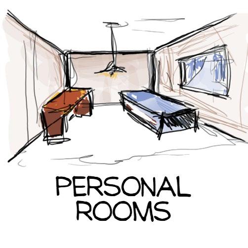
• Focus on interior functions
• Work-life balance
• Work in semi-defined spaces
• Flexibility
• Modern Technologies
• Green Architecture
Define Project Spaces
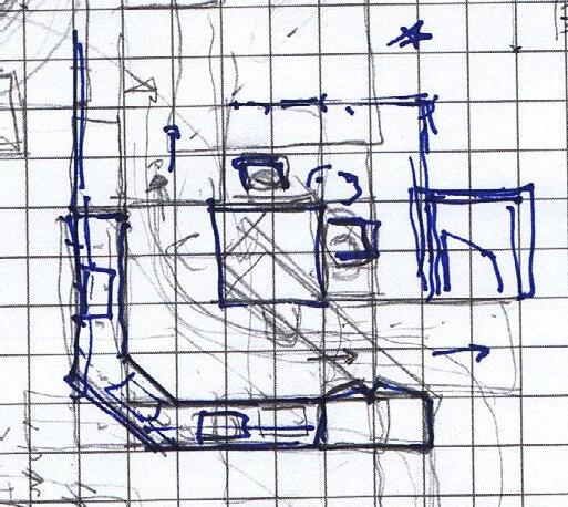
Preliminary Draft
Design Individual spaces, according to patterns
Final Design
Combining spaces from previous phase in one final project
Assembling The Pattern Language
Analysing
Project Brief From:
• The book "A pattern language"
• Reverse-Engineered Patterns from good houses
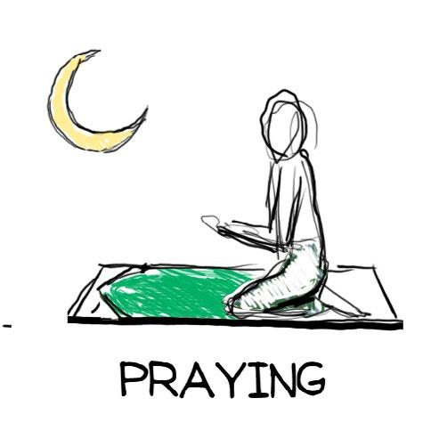
• Iranian culture, rituals and traditions
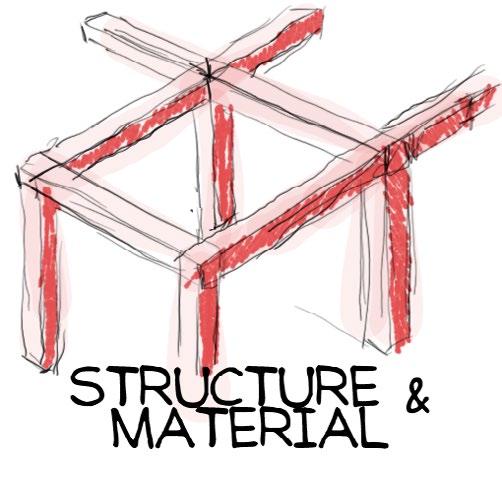
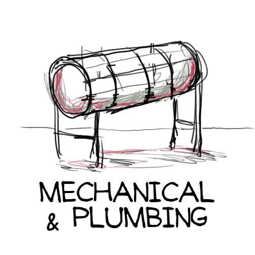
• Standard practices in Structure and MEP
• Local building codes
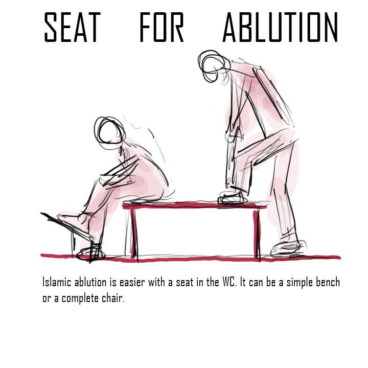
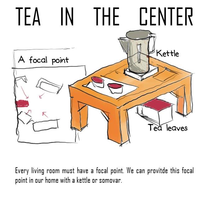
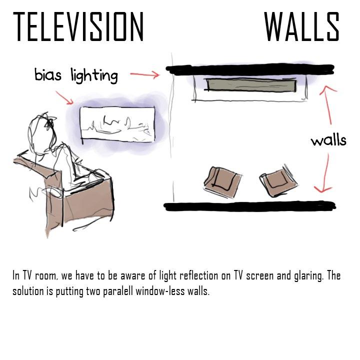
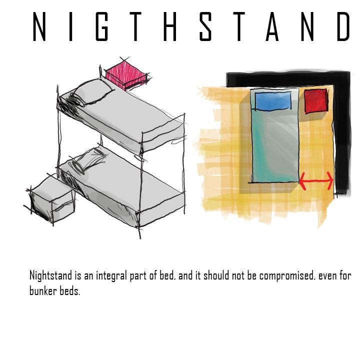
Examples of Patterns
Categories
160 patterns are classified in 24 categories
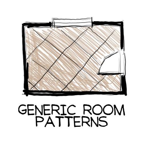
Space-Pattern Matrix
To design each space, we should know exact patterns that need to be implemented. The sheer number of patterns make tracking patterns of each space cumbersome. I chose to make a matrix between spaces and patterns. cell [i,j] is true if pattern[i] must be used in designing space[j]. This matrix is filled row by row, but used column by column. In each column, we find patterns that have to be considered to design a space. Considering a smaller group of patterns makes it easier to design a space.
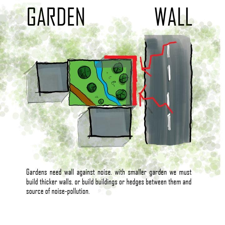
Courtyards which Live
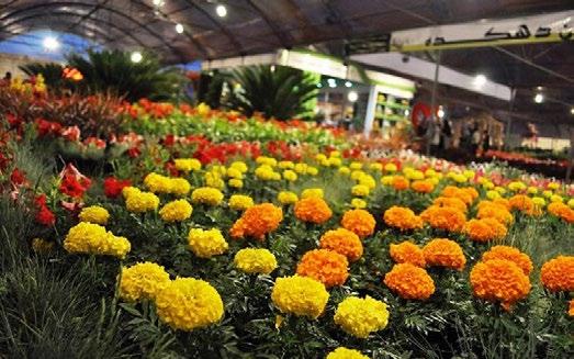
Sunny place
Six-foot Balcony
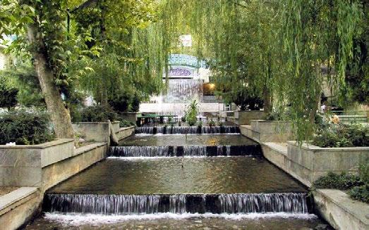
Howz and stream of water
Semi-transparent parapet
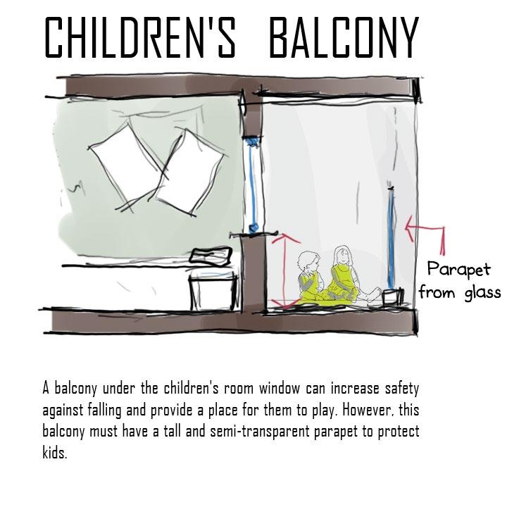
Children's balcony
Tree house, slide and swing
Three phases of work
Office pantry
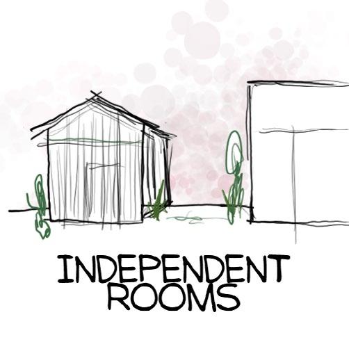
Workplace enclosure
Mee ng space details
Work circula on
Light on Two Sides of Every Room
Alcoves
Ceiling height variety
The shape of indoor space
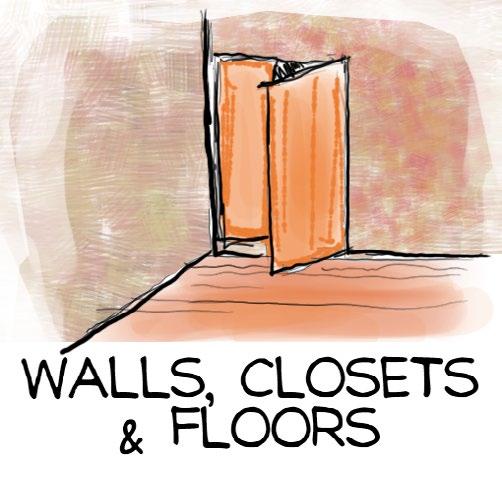
Half open wall
Interior Windows
Corner doors
full-length mirror
Sockets everywhere
Carpets for de
ning spaces
wireless room
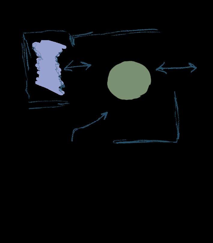
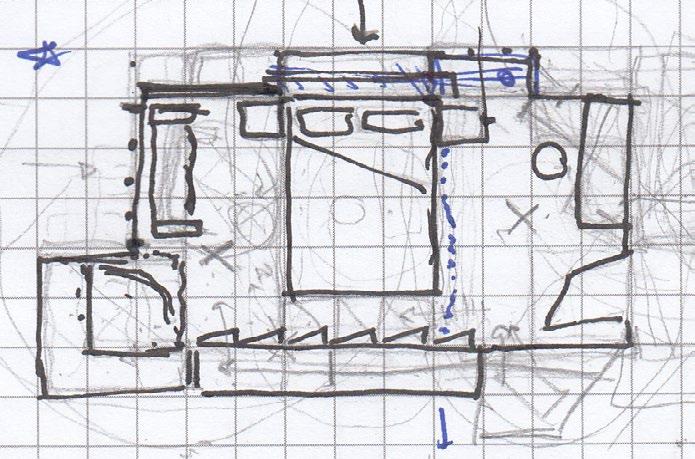
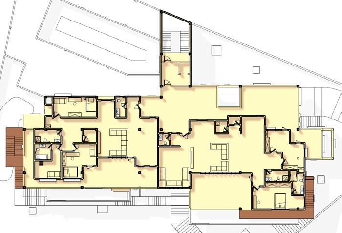
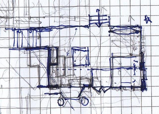
Preliminary Draft
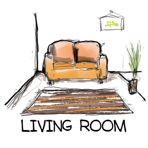
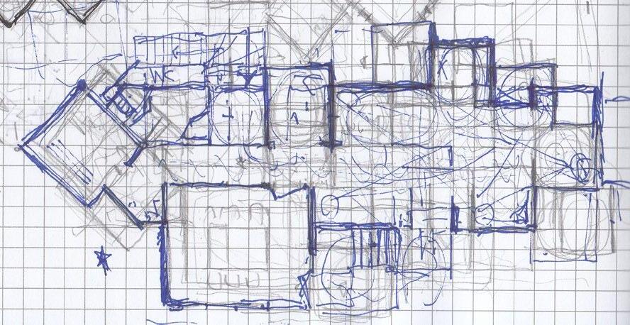
I started by drafting invidiual spaces (Kitchens, Living rooms, etc...) to find a feeling about specific charachteristics of each, ...
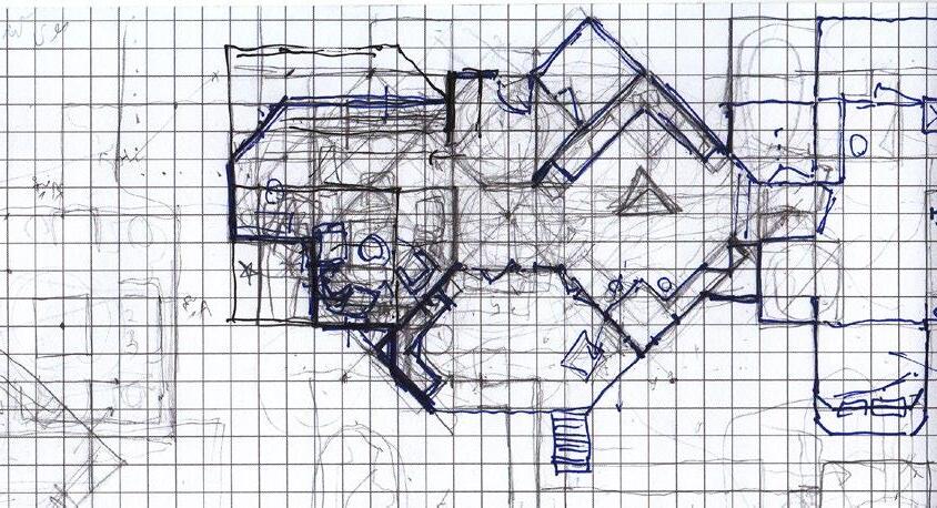
... Then Combining them into unit plans. The subspaces needed varous changes to be combined ...
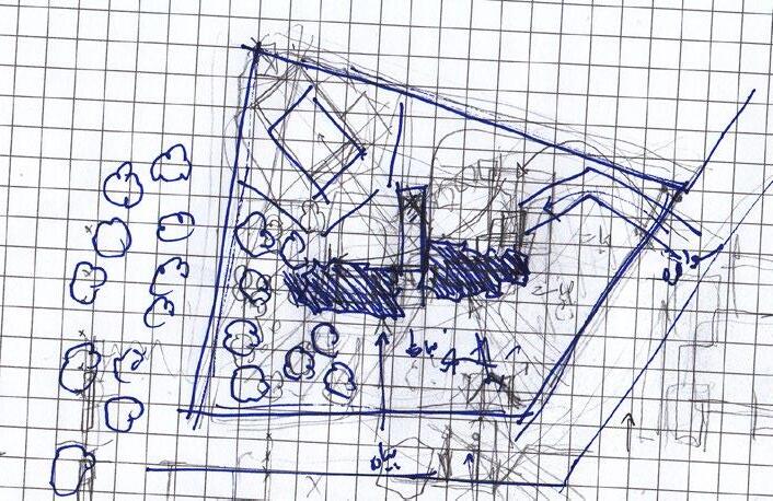
... After That, tried to combine individual plans with the same method.