8 minute read
A.3 Rethinking the Status Quo
Part A: Understanding Balcony Thermal Bridging
“Building envelope heat loss has historically been simplified due to past difficulties in cost-effectively providing more accuracy. This has generally led to overly optimistic assessments of building envelope performance by way of ignoring or underestimating the impact of thermal bridging.” 7
Buildings and construction together account for 36% of global final energy use and 39% of energy-related carbon dioxide (CO2 ) emissions8. Optimizing building energy use and reducing carbon emissions as they relate to balcony thermal bridging requires innovation and challenging the status quo in three main areas:
1. Introduction of higher performance requirements;
2. More accurate building performance energy modelling; and,
3. Understanding thermal bridging and updating traditional construction methodologies.
The following sections address these three main areas as they relate to balcony design and constructability, as well as overall building performance.
Part A: Understanding Balcony Thermal Bridging
Introduction of Performance Targets
With an increasing recognition of carbon emissions associated with buildings, there is a common drive towards carbon neutrality or zero emissions from buildings. Various policies and regulatory bodies are adopting performance-based targets with associated timelines for implementation, with zero emissions from new buildings by 2030 being a common goal.
This policy shift is evidenced at a variety of governmental levels:
• United Nations Framework Guidelines for Energy Efficiency Standards in Buildings; • Canadian Federal Build Smart program;
• BC Energy Step Code;
• City of Vancouver Zero Emissions Plan for New
Buildings Rezoning Policy; and,
• City of Toronto Zero Emissions Framework.
A shared methodology for achieving these goals within the BC Energy Step Code and City of Vancouver Green Building Rezoning Policy is to place limits or thresholds on the Energy Use Intensity (EUI, measured in kWh/m2a) of a building, and a specific limit on the requirements for heating or cooling the building, known as Thermal Energy Demand Intensity (TEDI, measured in kWh/m2a). “A key to meeting low thermal energy demand intensity (TEDI) for buildings is a holistic assessment of thermal bridging for thermal transmittance calculations. The biggest impact … is the quality of the details and design teams aggressively minimizing thermal bridging.” 9
Energy Modelling Guidelines
The approach and methodology to assess building performance is changing as codes are becoming progressively more stringent.
Traditionally building codes have been somewhat ambiguous about how to treat balconies (and thermal bridging in general) in terms of quantifying their impact on thermal performance. Previous versions of Canada’s National Energy Code for Buildings (NECB) (2011 and 2015) allowed the heat loss impacts of wall components encompassing a small percentage of the wall area to be ignored in code compliance calculations.
The City of Vancouver and Province of British Columbia are addressing this by implementing performance-based standards, a move away from improvement as compared to a reference building or a prescriptive checklist approach. These absolute targets on energy performance are coupled with the comprehensive City of Vancouver Energy Modelling Guidelines in order to ensure accurate prediction of performance. These guidelines are referenced at both the Municipal and Provincial level. The Architectural Institute of British Columbia and Engineers and Geoscientists of British Columbia have also introduced the concept of an energy modelling supervisor and a qualified modeler who will sign and seal the energy model as a means of ensuring quality control of the energy modelling process. In terms of treatment of balconies, the City of Vancouver Energy Modelling Guidelines10 Section 3.1.2 outlines:
Except where it can be proven to be insignificant, the calculation of the overall thermal transmittance of opaque building envelope assemblies shall include the thermal bridging effect of major structural penetrations, such as floor slabs, beams, girders, columns, curbs or structural penetrations on roofs and ornamentation or appendages that substantially or completely penetrate the insulation layer.
In practice this means that the energy modeler will input an effective R-value of the external opaque wall assembly that must consider the thermal bridging of the balcony (and other thermal bridges). This modelled effective R-value, used for illustrating compliance with the performance targets and for guidance on design strategies, should allow closer prediction of eventual performance. This in turn means that the architect and design team must understand how thermal bridges are measured and how the effective R-value of an assembly is calculated.
The contribution of details that are typically disregarded [in energy modeling] can result in the underestimation of 20% to 70% of the total heat flow through walls.” 11
Part A: Understanding Balcony Thermal Bridging
Understanding Thermal Bridging Methodologies
Thermal bridges are measured by assigning each penetration detail a thermal bridge loss coefficient. This is essentially an accounting principle that compensates for the difference in heat loss between that which is modelled based on assemblies alone and the actual heat loss through the detail.
BUILDING ENVELOPE THERMAL BRIDGING GUIDE v1.4 Point transmittance is the heat flow caused by thermal bridges that occur only at single, infrequent locations. This includes building components such as structural beam penetrations and intersections between linear details. The point transmittance is a single additive amount of heat, represented by chi ( ).
The actual heat loss is modelled in software such as THERM, HEAT 2 & 3 or Flixo or taken from a reference guide such as Building Envelope Thermal Bridging Guide². The Building Envelope Thermal Bridging Guide² is used as the source document in this report.
For linear thermal bridges, this value is known as the Psi (Ψ) value (W/mK). For point thermal bridges, the correction factor is known as the Chi (χ) value (W/K). The heat loss associated with thermal bridging of a balcony is a product of the linear length of balcony multiplied by the Psi (Ψ) value or, in the case of point connections, the number of point connections multiplied by the Chi (χ) value. This allows for subdivision of the balconies into categories; those that result in linear thermal bridge versus intermittent point thermal bridges. There are “U-value [or R-value] alone is a blunt slightly different calculation methodologies instrument for gauging the thermal depending on the guideline document or performance of a building” 12 standard referenced e.g. Building Envelope Thermal Bridging Guide², ASHRAE-1365-RP, ISO 10211, ISO 14683 and Passive House Institute (PHI). A comparison between the different calculation methodologies is outlined in the BC Housing publication, Low Thermal Energy Demand for Large Buildings13 . Once the thermal bridge heat loss coefficient has been identified for a detail it needs to be included in the calculation of the effective R-value. The impact of the thermal performance of different balcony connection details is illustrated in the Case Study in Part C of this report.
Figure 6: Example clear field assembly
Figure 7: Example linear transmittance of a floor slab detail
Figure 8: Example point transmittance of a beam penetration detail The overall U-value for any building envelope section is a simple addition and multiplication process. In straightforward terms this amounts to: ↑
Total Heat flow per area through the overall assembly Heat flow through linear transmittances+ Heat flow through point transmittances Total Area of assembly + Heat flow per area through clear field assembly Or, in mathematical terms:
Example linear transmittance of a floor slab detail
+���� ����
Where: UT = total effective assembly thermal transmittance (Btu/hr∙ft2∙oF or W/m2K) Uo = clear field thermal transmittance (Btu/hr∙ft2∙oF or W/m2K) Atotal = the total opaque wall area (ft2 or m2) = heat flow from linear thermal bridge (Btu/hr∙ft oF or W/mK) L = length of linear thermal bridge, i.e. slab width (ft or m) = heat flow from point thermal bridge (Btu/hr∙ oF or W/K) There are multiple types and quantities of linear and point transmittances, but they are all added to the clear field heat flow to get the overall heat flow of an area of the building envelope. The length for the linear transmittance depends on the detail. For example, the length used in the calculation for a floor slab bypassing the thermal insulation could be the width of the building perimeter, if this slab detail occurs around the whole façade of the building. Alternatively, a corner
Example point transmittance of a beam penetration detail
Examples of linear and point transmittance
As an example, the thermal bridge heat loss coefficient for the most common continuous slab balcony detail can be found in the Building Envelope Thermal Bridging Guide² under detail number 5.2.5 where a Psi (Ψ) value of 1.059 W/ mK is given2. The introduction of a proprietary thermal break to this detail can reduce this value to 0.4 W/mK whereas Passive House projects generally aim for thermal bridge free design where the Psi (Ψ) value is less than 0.01 W/mK.
To ensure occupant comfort, the thermal envelope needs to be as homogeneous as possible, to maintain even internal surface temperatures of the building fabric as close to the average ambient room temperature as possible. Thermal bridge calculations quantifying the Ψ (Psi)-value in W/mK will determine the heat flow through the detail but additional hygrothermal modelling (via WUFI or other similar software) or calculation of the temperature correction factor (fRSI) may be required to analyze condensation risk.
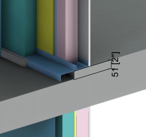
This guide uses the simple comparison of thermal bridge heat loss coefficients to underscore the importance of challenging current balcony construction methodologies and understanding alternative balcony connection details and their impact on the overall building performance. Appendix A: Catalogue Material Data Sheets BUILDING ENVELOPE THERMAL BRIDGING GUIDE v1.4 Detail 5.2.5 Exterior and Interior Insulated 3 5/8” x 1 5/8” Steel Stud (16” o.c.) Wall Assembly with Horizontal Z-girts (24” o.c.) Supporting Metal Cladding – Uninsulated Intermediate Floor Intersection with Uninsulated Curb
Thickness Inches (mm) Conductivity Btu∙in / ft2∙hr∙oF (W/mK) Nominal Resistance hr∙ft2∙oF/Btu (m2K/W) Density lb/ft3 (kg/m3) Specific Heat Btu/lb∙oF (J/kg K)

Balcony Stepdown Detail Balcony Stepdown Detail
Building Envelope Thermal Bridging Guide² pg.767 — Detail 5.2.5 Uninsulated Intermediate Floor Intersection with Uninsulated Curb

Part B


