7 minute read
Refrigeration
Controlling condenser flooding is often accomplished using two separate valves—typically ORI and ORD valves. By Greg Scrivener
In the last issue, we discussed methods for controlling the rejection of heat out of condensers and identified condenser flooding as one of the most effective methods. We are going to go into some of the details about how this works, specifically related to the typical method that uses two separate valves. There are also single valve solutions that work in a similar fashion.
Condenser flooding means using refrigerant to “flood” the condenser, which takes away surface area available for condensing and effectively makes the condenser smaller. Figure 1 shows the difference between these two cases.
Expanding our view of the system a little bit, Figure 2 shows the entire condensing portion of the system operating at 146 psig,
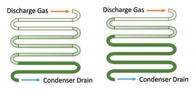
Figure 1: A condenser in normal operation and one partially flooded with refrigerant.
Continued on page “41”
The orange arrow is indicating where the differential pressure valve has been installed, while the green arrow points to the condenser flooding valve—installed on the condenser drain and hidden behind the suction line.

Continued from page “39”
which would be typical for a hot 95F day with R134A refrigerant. As the outdoor temperature cools off, the condenser will be able to reject more heat and eventually the symptoms we’ve discussed in the previous two articles will start to show up. Perhaps most importantly, we need the pressure to stay high enough to use that pressure drop to control our TX valves and distributor nozzles to make sure we have liquid refrigerant moving properly in the evaporator.
When the outdoor temperature cools off, the condenser fans can be cycled or staged to initially control the condensing pressure but in cold climates, this is usually not enough, and we have to start flooding the condenser.
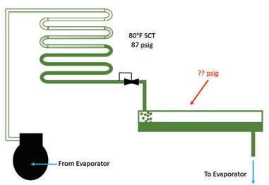
As you can see in this system, there is no way to hold back the refrigerant in the condenser and it becomes necessary to add a condenser flooding or hold-back valve in the condenser drain line. This valve is pressure operated and opens on a rise in inlet pressure; they are often called ORI valves. The setpoints are selected or adjusted to achieve a receiver pressure which is often (but does not always need to be) the pressure that corresponds to about 80F saturated condensing temperature. Figure 3 shows a system with this valve added. Notice what has changed in this system—some of the refrigerant is now being held in the condenser but it had to come from somewhere, so the receiver level has dropped. It is also worth considering what has happened to the pressure in the receiver. Since that condenser flooding valve is a pressure drop, the pressure in the receiver is going to be lower and you will recall, the entire point of this exercise is to keep the liquid pressure high enough.
Supplementing the pressure
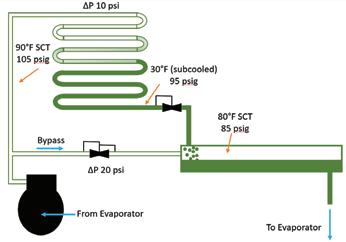
A flooding valve on its own doesn’t work and it is necessary to be able to supplement the pressure in the receiver. We maintain the pressure in the receiver by bypassing some discharge gas as shown in Figure 4. If we simply connected piping to the receiver,
the hot gas would bypass all the time in all modes of operation as the refrigerant chose the path of least resistance. It is therefore necessary to use some sort of method to make sure the pressure drop in the bypass line is higher than through the condenser in both normal operation and with the flooding valve holding back liquid. This can be done in a couple of ways but the economical and typical way in commercial refrigeration is to use a differential pressure regulator that opens on a rise in differential pressure; these are often referred to as ORD valves. They are also sometimes called differential pressure check valves; although this terminology is not entirely true because they modulate based on the differential pressure and don’t just snap fully open and closed. The most typical pressure drop setting for these valves is 20 psi, however, there are completely adjustable differential pressure regulators available that can be adjusted over a wide range. It is most important to ensure that the setting is higher than the pressure drop through the condenser and the pressure drop setting used to select the ORI. It is a tell-tale sign of something
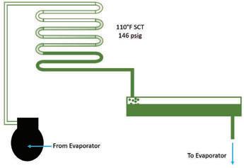
Figure 2: The condensing portion of a refrigeration system. Figure 3: The condensing portion of a refrigeration system with a condenser flooding valve.

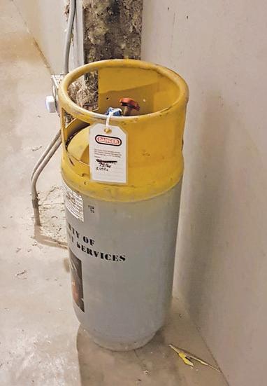
Guess what this refrigerant tank is for? Sometimes it is necessary to remove refrigerant in the summer and add it back in the winter when the receiver is undersized.
Continued on page “43”


Wholesalers offer a wide selection of head pressure flooding valves to choose from.
Figure 4: A typical ORD/ORI setup for R134A. This system is operating in cold weather as the refrigerant is being subcooled to 30F
Continued from page “41”
going wrong when you feel a warm bypass line in warm weather.
Size matters
Commercial valve manufacturers provide sizing methods for ORI and ORD type valves based on the pressure drop through the system. Figure 4 shows a typical set up and for this application you would be able to select the ORI based on a 10 psi pressure drop. The amount of discharge gas we need to bypass can be calculated (if you really want) by doing somewhat complex thermodynamic calculations. There are a lot of extra complexities surrounding what happens to the liquid and vapour in an operating receiver. Since the vessel has both, it must be saturated, but the process takes time, and the refrigerant is moving. Ignoring these extra complexities, when a condenser flooding valve is holding back liquid, leaves a lot of opportunity for subcooling. In very cold weather, the liquid can be extremely cold coming into the receiver. Since we know that the receiver is saturated because we have liquid and vapour present, the pressure would fall to the saturation pressure if we didn’t do something to increase the temperature. For example, if the system in Figure 4 had a bypass differential pressure valve that has failed to close, the pressure in the receiver would drop to less than 30 psig.
In order to stop the pressure from falling, we have to add enough discharge gas to heat up the liquid to an appropriate temperature. As discharge gas enters the receiver, it desuperheats and then condenses, rejecting its energy to the cold liquid. This in turn raises the pressure (and temperature) of the receiver and less hot gas condenses. This relationship means that we can control the pressure simply by bypassing the correct amount of hot gas.
Concerns with a receiver
The last potential concern in designing a system for condenser flooding is the receiver itself. We discussed earlier that when the condenser is flooding, that refrigerant has to come from somewhere and the only place it can come from is the receiver. This means that during the summer, the receivers for systems with condenser flooding need to be able to hold enough refrigerant to fill up whatever volume of condenser we expect we will need flooded in the winter. This is why it is best to employ the other methods of condenser head pressure control first. By cycling the fans, using variable speed fans, or splitting the condenser, we minimize how much needs to be filled with refrigerant. Once you’ve determined how much condenser you want to flood (often in the 80 per cent range), it is a simple volume calculation to make sure you have enough receiver. Recall that receivers are not allowed to have more than 90 per cent liquid and I would argue that in cold climates where this liquid could be cold, we should be using 80 per cent maximum. Undersized receivers are installed a lot and it is not uncommon to find a refrigerant tank hanging out around a system so someone can come in the fall and add the “winter charge” and then come back again in the spring and take the refrigerant out of the system so it doesn’t have high-head pressure problems when it gets hot. While not a method I would ever endorse, I suppose this does create repeat business. :
Greg Scrivener is the lead refrigeration engineer and a partner at Laporte Consultants, Calgary, and works throughout Canada and the U.S. He is a professional engineer and journeyperson refrigeration mechanic. He can be reached at GScrivener@laporteconsultants.com.
