
SPECIFICATIONS


Maximum Pressure/ Temperature Ratings
Consistent with applicable pressure / temperature ratings per ASME B16.34. Refer to Tables 17 to 19.
Maximum Allowable Shutoff Pressure Drop
Refer to Tables 18 & 19.
750 Psig (5,171 kPag)@ 100°F (38°C) (Standard Construction)
Material Temperature Capabilities
Valve Body:
Standard: -50°F to 450°F (-46°C to 232°C) LCC
Optional: High Temp -20°F to 800°F (-29°C to 427°C) wee
Packing:
PTFE: -50°F to 450°F (-46°C to 232°C)
Graphite: -325°F to 1000°F (-198°C to 538°C)
Live Loaded PTFE: -50°F to 450°F (-46°C to 232°C) (for 100 ppm service requirements)
Live Loaded Graphite: 20°F to 600°F (-7°C to 316°C) (for 100 ppm service requirements)
20°F to 700°F (-7°C to 371°C) (for non-environmental service requirements)
Refer to Tables 16 & 17.
Ball Seals:
Composition Ultra: -50°F to 450°F (-46°C to 232°C)
Metal: -50°F to 550°F (-46°C to 288°C)
Flow Ring: -325°F to 800°F (-198°C to 425°C)
Refer to Tables 18 & 19.
Construction Materials
Refer to Table 16 for construction materials.
Contact your Dyna-Flo sales office for more information and other options.
Flow Direction
Forward (through seal into ball).
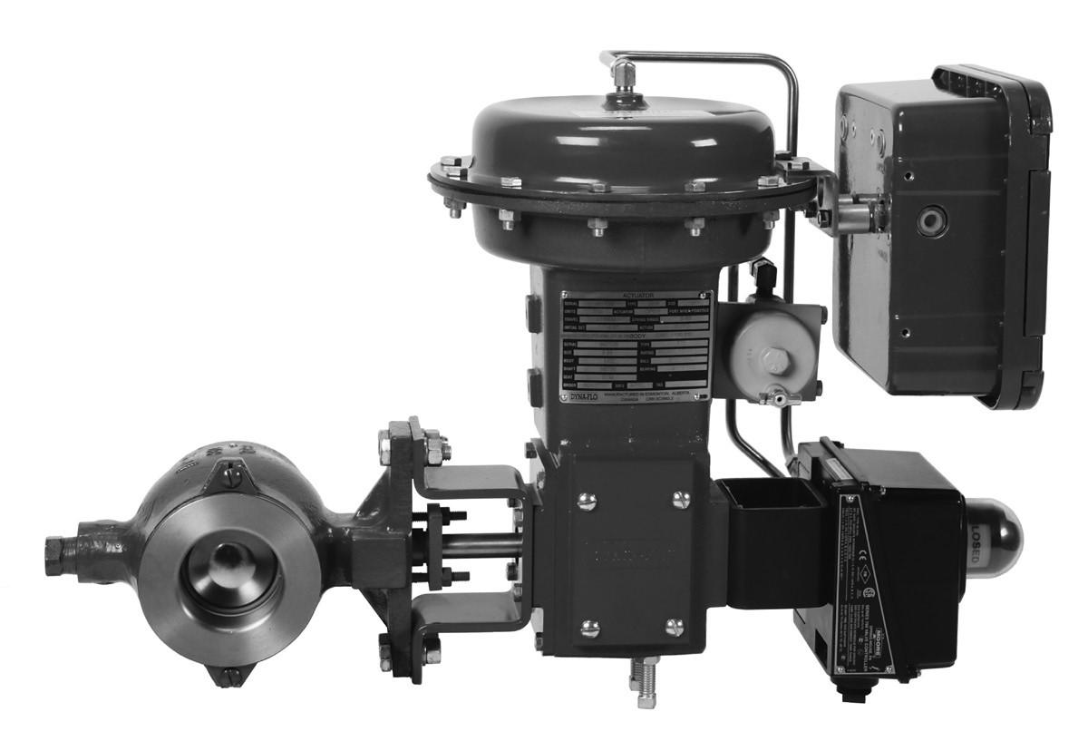
Actuator Mounting
Right-hand, or Left-hand (as viewed from seal end of valve). In one of 4 positions (12 (Std.), 3, 6, and 9 o'clock) with respect to the valve body in a horizontal pipe.
Maximum Ball Rotation
90 degrees.
Shutoff Classification
• Composition Ball Seal: Class VI
• Metal Ball Seal: Class IV
• Flow Ring Construction: 5% of valve capacity at full travel
• Classes and testing per ANSI/FCI 70-2 and IEC 60534-4.
• Tested at the service pressure drop, or 50 Psig (345 kPag), whichever is lower
Valve Dimensions
Refer to Figures 2 & 3 for valve diagram.
Refer to Tables 4 - 15 for valve dimensions.
Refer to Tables 7, 8, 12, & 13 for bolting dimensions.
Valve and Actuator Assembly Weight
Refer to Tables 2 & 3.
Options
Line Flange Bolting - Tables 7, 8, 12, & 13.
Stainless Steel Construction. Internal Coatings.
Shaft Connections:
- Splined (Standard)
- Square (Optional - 1" to 6" Valves)
- Keyed (Optional - 8" to 16" Valves)
For more information and other options contact your Dyna-Flo sales office.


Figure 3 Typical Valve Assembly Diagram and Dimensions
Model 570 Valve Dimensions Inch (mm)
Table 4

Model 571 and 573 Valve Dimensions Inch (mm)
Valve/
Ac tuator Size
1" / 4.00 (102)
(358) DFR026
1-1/2" 571 / 4.50 (114)
DFR026
1-1/2" 573 / 4.50 (114)
DFR026
2" / 4.88 (124)
(390) DFR026
3" / 6.50 (165)
DFR070 4"I
6" 571 / 9.00 (229)
DFR156
6" 573 / 9.00 (229) 6.25 (159) 6.44 (164)
(311) 21.56 (548) DFR156
B"I 9.56 (243) 7.69 (195) 9.12 (232) 14.92 (379) 24.24 (616) DFR156
10" / 11.69 (297) 8.75 (222) 10.25 (260) 16.05 (408) 26.62 (676) DFR220
12" / 13.31 (338) 10.56 (268) 11.94 (303) 17.74 (451) 28.31 (719) DFR220
16"571 / 16.00 (406) 13.00 (330) 14.38 (365) 23.65 (601) 30.93 (786) DFRP 113 16"573 / 16.00 (406) 13.31 (338) 14.38 (365) 23.65 (601) 30.93 (786) DFRP 113
(849)
Table 6 Valve Shaft Diameters Inch (mm)

Model 570 Line Flange Stud Lengths Refer to Figures 2 & 4.

Figure 4
Flange Stud Measuring Method

MEASURE FROM FIRST FULL THREAD TO FIRST FULL THREAD
Model 571 and 573 Flange Stud Lengths Inch (mm) Refer to Figures 2 & 4.

Model 570, 571, and 573 Splined Shaft Dimensions Inch (mm) Refer to Figures 2 & 4.
Model 570, 571, and 573 Square Shaft Dimensions Inch (mm) Refer to Figure 2.

Model 570, 571, and 573 Keyed Shaft Dimensions Inch (mm) Refer to Figure 2.
Flange Stud Diameters and Threads Per Inch {TPI)

Model 570 Valve Mounting Pad Dimensions Inch (mm) Refer to Figure 2.
Model 571 & 573 Valve Mounting Pad Dimensions Inch (mm) Refer to Figure 2.

Construction Materials
Part Description
Actuator Mounting Bolt / Actuator Mounting Nut
Back Up Ring (1, 1-1/2, 2" Valves Only)
Ball
Ball Seal
Bearing (2 required)
Material
Table 16
Plated Steel (2 required for 1 - 2" valves) (4 required for 3 - 12" vavles)
S31600**
Alloy 6 (for 1 - 2" valves)
CG8M
CG8M Chrome Plated
CG8M/Alloy 6 Leading Edge/Chrome Plated
CG8M/Alloy 6 Leading Edge
Composition Ultra
Alloy 6
S21800
Sl7400/Carbon-filled PTFE Lined OR PEEK/Carbon-filled PTFE
(Refer to Table 18 & 19)
S44004 HT
Alloy 6 LCC
Body / Seal Protector Ring / Flow Ring wee
CG8M
Follower Shaft / Shaft / Shaft Pin / Shaft Key S20910
Follower Shaft Pin
Gasket
Live Loaded Packing Follower
Packing Box Ring
Packing Flange / Packing Follower
Packing Nut (2 required)
Packing Set
Packing Stud (2 required)
Flange / Pipe Plug
S31600**
Graphoil GR. GTB
PTFE/CF8M
S31600**
CF8M
S31600**
PTFE
Graphite
B8M
Al0S Steel
A350 Grade LF2
S31600**
Flange Nut 2HM
Flange Stud
Radial Seal
Seal Protector Clip (2 required)
B7M
Carbon-filled PTFE/R30003
Stainless Steel
Seal Protector Screw - 1-1/2 to 12 inch (2 required) 18-8
Seal Protector Screw - 16 inch (4 required) 18-8
Seal Protector Washer (2 required)
Shaft Pins (for 16" valves)
Spiral Wound Gasket
Stainless Steel
Alloy 6
S31600
Spring Washers N07718
Thrust Washer (For 6 - 12 Inch Valve Sizes Only)
Carbon-filled PTFE
Wave Spring N07750
** All S31600 barstock is dual grade S31600/S31603 (316/316L).


SEAL PROTECTOR CLIP
SEAL PROTECTOR SCREW
SEAL PROTECTOR RING

FOLLOWER SHAFT


GASKET FLOW RING

FLOW RING SEAT DETAIL

SEAL: 1 -2 INCH METAL BALL SEAL

GASKET SIZE 3 THROUGH 12 INCH METAL BALL SEAL
9 Ball Seal Assembly Diagrams - Continued

SEAL PROTECTORWASHER
SEAL PROTECTORSCREW
PROTECTOR RING


PIPEPLUG FLANGE STUD
RING

SPIRALWOUND GASKET BALLSEAL GASKET
SEALPROTECTOR SCREW BALL


PTFE V-RING PRESSURE PACKING
PTFE V-RING VACUUM PACKING
GRAPHITE PRESSURE PACKING


V-RING PACKING SET
GRAPHITE PACKING SET
PACKING FLANGE
SPRING WASHERS
LIVE LOADED PTFE V-RING PRESSURE PACKING
LIVE LOADED GRAPHITE PRESSURE PACKING +----LIVE LOADED--PACKING FOLLOWER

ANTI-EXTRUSION RING

GRAPHITE PACKING SET
NOTE: Packing arrangements may differ from those shown above depending on valve size and application. Refer to the Model 570, 571, 573 Instruction Manual (P-570M) for more information on packing arrangements.

PressureTemperatureRatingsasperASMEB16.34. Forratingsabove800°F(427 °C)consultfactory.
Notes:
1 -Donotuseover650°F(343 °C)

(-46to38)
(-46to260)
(-46to260)
(1,082) (1,117)
160 (1,117) (1,103)

NOTE: Do not exceed the pressure/temperature rating of the valve body material as per Table 16.

Valve Sizing Coefficients
ForwardFlow,CompositionAndMetalSeals1:1PipeToValveSizeRatio

570 570 571 571
1 1 INCH 5 1-1/2 INCH 4INCH 6 6INCH 12 12 INCH 16 16 INCH
- CG8M/ CRPL (STANDARD)
N CG8M/ Alloy 6 LEADING EDGE
A 150 B 300/ 600
L LCC w wee
A ALLOY 6 H S21800
- DFPS-01 (STANDARD)
3 DFPS-03 (HIGH TEMPERATURE)
p SINGLE PTFE V-RING
V SINGLE PTFE V-RING (VACUUM)
G SINGLE GRAPHITE
N SPLINED

SAMPLE PART NUMBER: 570-2-CLC-PNT --
MODEL 570 573 I 573
VALVE SIZE
2 j 2 INCH 3 3 INCH 8 j 8 INCH 10 j 10 INCH
BALL MATERIAL
s j CG8M/ Alloy 6 LEADING EDGE/ CRPL -
B j CG8M
ASME RATING (SEE PAGE 2) C
C J 150/ 300/ 600 E 300
BODY MATERIAL L
C j CG8M
BALL SEAL MATERIAL C C I COMPOSITION ULTRA s FLOW RING PAINT
2 j DFPS-02 (SEVERE SERVICE) -
STYLE L I LIVE LOADED PTFE T I LIVE LOADED GRAPHITE
K I KEYED(VALVESIZES 8" - 16" ONLY) N
p SQUARE END (VALVE SIZES 1" - 6" ONLY. FOR 1" & 1-1/2" VALVES CONSULT DYNA-FLO)
BEARINGS
T S17400 I CARBON-FILLED PTFEl1> T I PEEK/ CARBON-FILLED PTFEI') T A ALLOY 6 F J S44004
NOTES
1 BEARING MATERIAL WILL VARY DEPENDING ON VALVE SIZE, REFER TO TABLE 18 & 19 FOR MORE INFORMATION.
Curtiss-Wright Flow Control Company Canada is committed to continuous improvement. While all efforts have been made to ensure the accuracy of the content in this document, modifications or improvements to the information, specifications, and designs may occur at any time without notice. This document was published for informational purposes only, and does not express or imply suitability, a warranty, or guarantee regarding the products or services described herein or their use or applicability.
Neither Curtiss-Wright Flow Control Company, nor any of their affiliated entities assumes responsibility for the selection, use and maintenance of any product. Responsibility for selection, use and maintenance of any product remains with the purchaser and end-user. Curtiss-Wright Flow Control Company Canada, doing business
Phone: 780 • 469 • 4000

Find your local Distributor:
2680 New Butler Rd. New Castle, PA 16101
Tel: 724-368-8725
Email: sales@portersvilleprd.com
700 Southlake Blvd. North Chesterfield VA 23236
Tel: 804-593-2384
Email: sales@portersvilleprd.com
www.portersvilleprd.com
143 S.Thomas Rd. Tallmadge, OH 44278
Tel: 330-253-4800
Email: sales@portersvilleprd.com
1551 Shipley Ferry Road Blountville, TN 37617
Tel: 423-482-0496
Email: sales@portersvilleprd.com
403 Technology Dr South Point, OH 45680
Tel: 740-377-0018
Email: sales@portersvilleprd.com
3915 Beryl Road, Raleigh NC 27607
Tel: 984-238-1720

Email: sales@portersvilleprd.com