


Valve Group 197C
2700
Engineering
Series
Farris
Pressure Relief Valves
Table of Contents Introduction
Designed to provide customers with the widest selection of sizes, orifices and construction materials, Series 2700 meets the exacting demands of the process industry.
Superior Design
A single design handles air, steam, vapor and liquid services. Maximum interchangeability of parts affords easy maintenance and lower costs.
Fixed blowdown design simplifies testing and repair. Maximum blowdown of 5% to 15% regardless of service.1
A built-in lift stop ensures stable performance.
Balanced design in “C” and “D” orifices nullifies the effects of back pressure on set point.
ASME Code Certification
Manufactured in conformance to Section VIII of the ASME Boiler and Pressure Vessel Code for air, steam, and water service.
Capacities certified by The National Board of Boiler and Pressure Vessel Inspectors.
Optional O-Ring Seat Design
O-ring seat design available for maximum seat tightness.
Teflon® available at higher pressures to provide the same zero bubbles per minute leakage as elastomer O-ring seats.
Comprehensive Product Line
Set pressures from 15 psig to 6500 psig with orifice areas from 0.068 to 0.573 sq. in.
Standard valves have MNPT inlet x FNPT outlet. Optional female inlet thread, flanged, socket weld, welding nipple, and sanitary connections available.
Maximum Selection of Materials
Standard construction includes 316 stainless steel body, trim and spring, with carbon steel bonnet.
Optional materials include Monel®, Hastelloy C®, and materials suitable for NACE service.
Warranty
General Notes:
1. Blowdown on liquid service may slightly exceed 15% in certain applications.
Teflon is a registered trademark of the DuPont Company.
Monel is a registered trademark of Inco Alloys International Inc.
Hastelloy and Hastelloy C are registered trademarks of Haynes International Inc.
All products manufactured by Farris Engineering are warranted free of defects in material and workmanship when used within the range recommended for a period of one year after installation or eighteen months from delivery. When authorized, any defective product may be returned to the factory and if found defective will be repaired or replaced free of charge, solely at the discretion of Farris Engineering, ex-works our factory. No charge for labor or other expense incurred will be allowed, as the liability of Farris Engineering is measured by the refund price of the defective product only. All warranties are based on the product being used within the range recommended and does not cover damages or defects due to normal wear and tear, misuse, alteration or neglect. The purchaser shall determine the suitability of the product for use and assumes all risks and liabilities in connection therewith.
This warranty does not cover the performance of valves tested at site on test equipment that is not to the same technical standard as that used by the manufacturer.
General Description IFC Ordering Information & Numbering System 1 Bill of Materials-Conventional 2 Bill of Materials-Balanced Design 3 Selection Table: O-Ring Design .................................................................. 4 Selection Tables – Conventional Design U.S. Customary Units Threaded Connections ........................................................................ 4 Flanged Connections 5 Selection Tables – Balanced Design U.S. Customary Units Threaded Connections 6 Flanged Connections 6 Special Materials 7 Capacity Tables – U.S. Customary Units Air 8 Steam 8 Water 9 Selection Tables – Conventional Design Metric Units Threaded Connections 10 Flanged Connections 11 Selection Tables – Balanced Design Metric Units Threaded Connections 12 Flanged Connections 12 Capacity Tables – Metric Units Air 13 Water 13 Steam ............................................................................................... 14 Cap Constructions 14 Dimensions & Weights 15-16 Other Farris Engineering Valves 17
Numbering System
Selecting and specifying Farris pressure relief valves is simple using the numbering system that follows. Each digit of the type number has a distinct significance. The digits describe the basic valve series, orifice, seat design, inlet temperature range, body, bonnet and spring material, inlet type and pressure rating.
Ordering Information
Please specify the following so that we may process your order as quickly as possible.
1. Quantity.*
2. Inlet and outlet sizes.
3. Farris type number.*
4. Inlet and outlet connections: MNPT, FNPT, flanged, socket weld, sanitary inlet or welding nipple.
5. Materials of construction if other than standard.
6. O-ring seat pressure seal material, if required.
7. Set pressure.*
8. Operating and relieving temperatures.*
9. Allowable overpressure.*
10. Fluid and fluid state.*
11. Backpressure, superimposed constant and/or variable, and built-up.*
12. Required capacity.*
13. Accessories: open or packed lever if required; test gag.
14. Code requirements, if any.
*As a customer service, we verify your selection and sizing. In order to do this, we must have this information.
General Notes:
1. Not all combinations of inlet and outlet sizes shown are available. Consult the selection tables of pages 4 and 5.
2. Test gag option is not available with open lever cap.
3. Available in O-ring seat design only. Consult the Farris Factory.
4. Duplex stainless steel available upon request, consult the factory.
5. Selection of proper soft good material is customer’s responsibility.
1
27
Series Number Orifice Area Seat Construction5 Inlet Size1 Outlet Size1 Special Variations Inlet Connections Cap Construction Test Gag 2 Special Materials 27US Customary Units Sq. In. C 0.068 D 0.125 E 0.223 F 0.350 G 0.573 Metric mm2 C 43.87 D 80.65 E 143.87 F 225.81 G 369.68 A Metal Seat C Soft Seat T Teflon Seat 1 1/2" 2 3/4" 3 1" 4 1-1/2" 3 1" 4 1-1/2" 5 2" 6 2-1/2" H High pressure variations of standard types B Balanced design3 D Heat transfer fluid standard pressure E Heat transfer fluid high pressure M MNPT F FNPT 1 Flanged-150RF 2 Flanged-300RF 3 Flanged-600RF 4 Flanged-900RF 5 Flanged-1500RF 6
O Special S Socket Weld T Sanitary W Welding Nipple 2 Plain 4 Packed Lever 7 Open Lever 0 No Gag 1 Test Gag S4 Complete 316 St. St. N1 NACE Trim: Standard N4 NACE Trim: All St. St. M1 Monel Body & Disc M2 Monel Internals M4 Complete Monel H1 Hastelloy C Body & Disc H2 Hastelloy C Internals H4 Complete Hastelloy C
DA23 H – M20 /S44
Flanged-2500RF
2700 Series – Conventional
2
Bill of Materials – Conventional Item Part Name Standard Material 1 Body SA-351 Gr. CF8M St. St. or SA-479 Type 316 St. St. 2 Bonnet SA-216 Gr. WCB, Carb. St. 3 Disc 316 St. St. 4 Guide 316 St. St. 5 Disc Holder 316 St. St. 6 Stem 316 St. St. 7 Spring Adj. Screw 316 St. St. 8 Jam Nut 316 St. St. 9 Cap, Plain ScrewedCarbon Steel 10 Cap Gasket 316 St. St. 11 Body Gasket 316 St. St. 12 Guide Gasket 316 St. St. 13 Spring (-50°F to +750°F)Stainless Steel 14 Spring Buttons 316 St. St. 15 Wire Seal St. St. Wire / Lead Seal 16 Nameplate (Not Shown)Stainless Steel 17 Welding Nipple (Inlet)316 St. St. 18 Welding Nipple (Outlet)Carbon Steel 19 Lap Joint Stub End (Inlet)316 St. St. 20 Lap Joint Stub End (Outlet)Carbon Steel 21 Lap Joint Flange (Inlet)Carbon Steel 22 Lap Joint Flange (Outlet)Carbon Steel Complies with ASME Boiler & Pressure Vessel Code, Section VIII 9 8 7 6 4 12 11 5 3 2 1 10 13 15 14 O-Ring Design (Optional) Welded End Design (Optional) Flanged Design (Optional) O-Ring Retainer O-Ring Seat Seal Retainer Lockscrew 20 22 21 19 18 17
2700 Series – Balanced Design
Do you have variable back pressure? Can’t use a balanced bellows design? Farris has the solution with the Series 2700 Balanced Design pressure relief valve. The balanced effect is achieved by isolating the upper valve chamber and eliminating any back pressure build-up in the bonnet affecting valve set pressure.
These valves are available in 1/2", 3/4" and 1" inlet sizes with a 1" outlet and two orifice areas. Pressure ranges from 15 to 1480 psig, standard soft seat design. Flanged and welded inlet and outlet connections are available with the same material options as the standard design.
3
Series 2700 Back Pressure Correction Factor, Balanced Design Bill of Materials – Balanced Design Item Part Name Standard Material 1 Body SA-351 Gr. CF8M St. St. or SA-479 Type 316 St. St. 2 Bonnet SA-216 Gr. WCB, Carb. St. 3 O-ring Retainer 316 St. St. 4 O-ring Seat Seal Viton® 5 Retainer Lock Screw304 St. St. 6 Guide 316 St. St. 7 Guide Seal Viton 8 Disc Holder 316 St. St. 9 Disc Holder Seal Viton 10Stem 316 St. St. 11 Spring Adj. Screw 316 St. St. 12 Jam Nut 316 St. St. 13 Cap, Plain ScrewedCarbon Steel 14 Cap Gasket 316 St. St. 15 Body Gasket 316 St. St. 16 Guide Gasket 316 St. St. 17Spring Stainless Steel 18 Spring Buttons 316 St. St. 19 Wire Seal St. St. Wire/Lead Seal 20 Nameplate (Not Shown)Stainless Steel Complies with ASME Boiler & Pressure Vessel Code, Section VIII General Notes: 1. Other O-ring materials available. Consult the factory. 2. Flanged, socket weld, welding nipple and female inlet threaded designs available. 3. Temperature for balanced or O-ring seat design is limited by the elastomer selected. See page 4. Viton is a registered trademark of DuPont Elastomers.
13 10 11 12 19 14 18 17 2 6 9 7 15 16 8 5 4 3 1 Bonnet Vent 0% 0 0.2 0.4 0.6 0.8 1 1.2 Percent Back Pressure K b (Gas) K w (Liquid) Back Pressure Correction Factor 5% 10%15% 20%25%30%40%50%60%70% 80% 35%45%55%65%75%
O-Ring Selection
The 2700 Series is available with an optional O-ring seat which minimizes fugitive emissions and costly product loss. This optional seat construction provides zero bubbles per minute leakage at 90% of set pressure per API Standard 527. The tables below list the set pressure and temperature range for both the elastomer and PTFE seat options.
O-Ring Seat Valve Pressure & Temperature Limits
Material Availability
General Notes:
1. Maximum O-ring set pressure limit cannot exceed the pressure limit for a given type number and size as indicated in the metal seat selection tables.
2. Temperature range may vary depending on service fluid.
3. Ethylene propylene is suitable for steam service up to 350°F, PTFE up to 500°F.
4. Consult the Farris Factory for other materials.
5. We reserve the right to substitute comparable fluorocarbon materials from other manufacturers.
Selection Table – Conventional Design
(see notes on page 5)
Kalrez is a registered trademark of DuPont Elastomers.
4
Threaded Connections – MNPT x FNPT, U.S. Customary Units Orifice Area Sq. In. Valve Size Inlet x Outlet Type Number Maximum Set Pressure, psig Max. Back Pressure psig at 100°F Materials -50°F to 750°F Body / Bonnet Spring 0.068 1/2 x 1 3/4 x 1 3/4 x 1 1 x 1 1 x 1 27CA13-M20 27CA23-M20 27CA23H-M20 27CA33-M20 27CA33H-M20 1600 2500 5000 2500 6500 400 316 St. St./ Carb. St. Stainless Steel 0.125 1/2 x 1 3/4 x 1 3/4 x 1 1 x 1 1 x 1 27DA13-M20 27DA23-M20 27DA23H-M20 27DA33-M20 27DA33H-M20 1600 1600 5000 1600 5000 400 316 St. St./ Carb St. Stainless Steel 0.223 1 x 1-1/2 27EA34-M20 2500 400 316 St. St./ Carb. St. Stainless Steel 0.350 1-1/2 x 2 27FA45-M20 1600 400 316 St. St./ Carb. St. Stainless Steel 0.573 1-1/2 x 2-1/2 27GA46-M20 1000 400 316 St. St./ Carb. St. Stainless Steel
Orifice Pressure Range, psig1 Pressure Range, barg1 Elastomer Seat PTFE Seat Elastomer Seat PTFE Seat C High Pressure 15 to 1480 800 to 2500 2501 to 6500 1.0 to 102 55.1 to 172 172.1 to 345 D High Pressure 15 to 1480 800 to 1600 1601 to 6500 1.0 to 102 55.1 to 110 110.1 to 345 E 15 to 1480 600 to 2500 1.0 to 102 41.3 to 172 F 15 to 1480 600 to 1600 1.0 to 102 41.3 to 110 G 15 to 1000 200 to 1000 1.0 to 69 14 to 69
Material Temperature Range2 °F °C Viton®5 -20° to +450° -29° to +232° Nitrile -20° to +250° -29° to +121° EPDM 0° to +350° -18° to +177° Silicone -150° to +450°-101° to +232° Kalrez® -20° to +550° -29° to +289° PTFE -300° to +500°-184° to +260°
Selection Table – Conventional Design
Flanged Connections, U.S. Customary Units
1/2 x 1
3/4 x 1
27CA23-420
27CA23H-520 27CA23H-620
General Notes:
1. Available with optional elastomer or Teflon seat design as illustrated. Change the fourth digit of the type number from “A” to “C” for soft seat, “A” to “T” for Teflon. Example: 27DC23-M20 for soft seat, 27DT23-M20 for Teflon. See Selection Table for pressure and temperature limits.
2. Above type numbers indicate standard materials of construction. To select corrosive or low temperature materials, add type number suffix as indicated on pages 1 and 7.
3. Available in materials suitable for sour gas (H2S) service to NACE Standards MR0103 and MR0175 / ISO 15156. Add “N1” (standard materials) or “N4” (all stainless construction) to the type number. Example 27DA23-M20/N1 & 27DA23-M20/N4.
4. For open or packed levers, change the second digit of the type number suffix. Examples: 27FA45-M70 for open lever, 27GA46-M40 for packed lever.
5. For socket weld or welding nipple connections, change the first digit of the type number suffix to “S” for socket weld or “W” for welding nipple inlet and outlet. Examples: 27DC33-S20 for socket weld, 27DA33-W20 for welding nipple. Maximum set pressures are identical to the MNPT inlet up to 500°F. For Temperatures above 500°F, consult the factory.
6. Female threaded inlet available. Change first digit of the type number suffix to “F”. Example: 27EA34-F20. Maximum set pressure for female inlet is identical to male inlet except for 1/2 x 1" C orifice which may be set to max set pressure of 2500 psig.
7. For set pressures below 15 psig, consult the Farris Factory.
5
Orifice Area Sq. In. Valve Size Inlet x Outlet ANSI Flange Class Type Number Maximum Set Pressure, psigMax. Back Pressure psig at 100°F Materials Inlet RFOutlet RF -50°F to 100°F 400°F750°F Body / Bonnet Spring 0.068 1/2
1 150# 300# 600# 900# 1500# 2500# 150# 150# 150# 300# 300# 300#
27CA13H-520 27CA13H-620 285 740 1480 2220 3705 5000 200 635 1270 1900 3170 5000 95 505 1010 1510 2520 4200 285 285 285 400 400 400 316 St. St./ Carb. St. Stainless Steel
1 150# 300# 600# 900# 1500# 2500# 150# 150# 150# 300# 300# 300#
x
27CA13-120 27CA13-220 27CA13-320 27CA13-420
3/4 x
27CA23-120 27CA23-220 27CA23-320
285 740 1480 2220 3705 5000 200 635 1270 1900 3170 5000 95 505 1010 1510 2520 4200 285 285 285 400 400 400 316 St. St./ Carb St. Stainless Steel 1 x 1 150# 300# 600# 900# 1500# 2500# 150# 150# 150# 300# 300# 300# 27CA33-120 27CA33-220 27CA33-320 27CA33-420 27CA33H-520 27CA33H-620 285 740 1480 2220 3705 6170 200 635 1270 1900 3170 5280 95 505 1010 1510 2520 4200 285 285 285 400 400 400 316 St. St./ Carb. St. Stainless Steel 0.125
150# 300# 600# 900# 150# 150# 150# 300# 27DA13-120 27DA13-220 27DA13-320 27DA13H-420 285 740 1480 2220 200 635 1270 1900 95 505 1010 1510 285 285 285 400 316 St. St./ Carb. St. Stainless Steel
150# 300# 600# 900# 1500# 2500# 150# 150# 150# 300# 300# 300#
285 740 1480 2220 3705 5000 200 635 1270 1900 3170 5000 95 505 1010 1510 2520 4200 285 285 285 400 400 400 316 St. St./ Carb. St. Stainless Steel
150# 300# 600# 900# 1500# 2500# 150# 150# 150# 300# 300# 300# 27DA33-120 27DA33-220 27DA33-320 27DA33H-420 27DA33H-520 27DA33H-620 285 740 1480 2220 3705 6170 200 635 1270 1900 3170 5280 95 505 1010 1510 2520 4200 285 285 285 400 400 400 316 St. St./ Carb. St. Stainless Steel
1
150# 300# 600# 900# 150# 150# 150# 300# 27EA34-120 27EA34-220 27EA34-320 27EA34-420 285 740 1480 2220 200 635 1270 1900 95 505 1010 1510 285 285 285 400 316 St. St./ Carb. St. Stainless Steel 0.350 1-1/2 x 2 150# 300# 600# 150# 150# 150# 27FA45-120 27FA45-220 27FA45-320 285 740 1480 200 635 1270 95 505 1010 285 285 285 316 St. St./ Carb. St. Stainless Steel
150# 300# 600# 150# 150# 150# 27GA46-120 27GA46-220 27GA46-320 285 740 1000 200 635 1000 95 505 1000 285 285 285 316 St. St./ Carb. St. Stainless Steel
27DA23-120 27DA23-220 27DA23-320 27DA23H-420 27DA23H-520 27DA23H-620
1 x 1
0.223
x 1-1/2
0.573 1-1/2 x 2-1/2
Selection Tables – Balanced Design (see
notes on page 5)
Threaded Connections – MNPT x FNPT, U.S. Customary Units
Flanged Connections, U.S. Customary Units
6
Orifice Area Sq. In. Valve Size Inlet x Outlet Type Number Maximum Set Pressure, psig Max. Back Pressure psig at 100°F Materials -20°F to 450°F Body / Bonnet Spring 0.068 1/2 x 1 3/4 x 1 1 x 1 27CC13B-M20 27CC23B-M20 27CC33B-M20 1480 400 316 St. St./ Carb. St. Stainless Steel 0.125 1/2 x 1 3/4 x 1 1 x 1 27DC13B-M20 27DC23B-M20 27DC33B-M20 1480 400 316 St. St./ Carb St. Stainless Steel
Orifice Area Sq. In. Valve Size Inlet x Outlet ANSI Flange Class Type Number Maximum Set Pressure, psig Max. Back Pressure psig at 100°F Materials Inlet RFOutlet RF -20°F to 100°F 400°F Body / Bonnet Spring 0.068 1/2 x 1 150# 300# 600# 900# 150# 150# 150# 300# 27CC13B-120 27CC13B-220 27CC13B-320 27CC13B-420 285 740 1480 1480 200 635 1270 1270 285 285 285 400 316 St. St./ Carb. St. Stainless Steel 3/4 x 1 150# 300# 600# 900# 150# 150# 150# 300# 27CC23B-120 27CC23B-220 27CC23B-320 27CC23B-420 285 740 1480 1480 200 635 1270 1270 285 285 285 400 316 St. St./ Carb St. Stainless Steel 1 x 1 150# 300# 600# 900# 150# 150# 150# 300# 27CC33B-120 27CC33B-220 27CC33B-320 27CC33B-420 285 740 1480 1480 200 635 1270 1270 285 285 285 400 316 St. St./ Carb. St. Stainless Steel 0.125 1/2 x 1 150# 300# 600# 150# 150# 150# 27DC13B-120 27DC13B-220 27DC13B-320 285 740 1480 200 635 1270 285 285 285 316 St. St./ Carb. St. Stainless Steel 3/4 x 1 150# 300# 600# 150# 150# 150# 27DC23B-120 27DC23B-220 27DC23B-320 285 740 1480 200 635 1270 285 285 285 316 St. St./ Carb. St. Stainless Steel
x 1 150# 300# 600# 150# 150# 150# 27DC33B-120 27DC33B-220 27DC33B-320 285 740 1480 200 635 1270 285 285 285 316 St. St./ Carb. St. Stainless Steel
1
Special Materials
Corrosive & Low Temperature Service
Guide Seal5
Disc Holder Seal5
Wire
General Notes:
1. Any part where material field is blank is standard material.
2. For S4 trim, a 17-4 Ph. or 17-7 Ph. spring may be necessary for some pressures and temperatures.
3. For open and packed lever materials, see page 14.
4. Maximum set pressures for S4, M4, and H4 trim are the same as the carbon steel valves or the 316 St. St., Monel and Hastelloy C flange limits respectively, whichever is lower.
5. Temperature for balanced or O-ring seat design is limited by the elastomer selected. Consult chart on page 4.
6. Balanced design uses the same spring selection as the standard design. Where NACE compliant trim is specified, all trim classes for both conventional and balanced designs use springs made from Inconel X-750.
Inconel and Inconel X-750 are registered trademarks of Inco Alloys International. We reserve the right to substitute comparable material from other suppliers.
7
Part Name 316 St. St. Monel Hastelloy C N1 (NACE)S4 & N4 (NACE) M1M2M4 H1 H2 H4 -50°F to 750°F-450°F to 750°F2 -50°F to 600°F -325°F to 600°F -50°F to 500°F -325°F to 500°F Body MonelMonelMonel Hastelloy CHastelloy CHastelloy C Bonnet SA-351 Gr. CF8M St. St. Monel Hastelloy C Disc MonelMonelMonel Hastelloy CHastelloy CHastelloy C Guide MonelMonel Hastelloy CHastelloy C Disc Holder MonelMonel Hastelloy CHastelloy C Stem Monel Hastelloy C Spring Adj. Screw Monel Hastelloy C Jam Nut Monel Hastelloy C Cap, Plain Screwed 316 St. St. Monel Hastelloy C Cap Gasket Monel Hastelloy C Body Gasket MonelMonel Hastelloy CHastelloy C Guide Gasket MonelMonel Hastelloy CHastelloy C Spring6 Inconel® X-750 316 St. St./ Inconel X-750 Inconel X-750 Inconel X-750 Inconel X-750 Hastelloy C Spring Buttons Monel Hastelloy C O-Ring Retainer5 316 St. St. MonelMonelMonel Hastelloy CHastelloy CHastelloy C Retainer Lock Screw5 316 St. St. MonelMonelMonel Hastelloy CHastelloy CHastelloy C
O-Ring Seat Seal5
Welding Nipple (Inlet) MonelMonelMonel Hastelloy CHastelloy CHastelloy C Welding Nipple (Outlet) 316 St. St. Monel Hastelloy C Lap Joint Stub End (Inlet) MonelMonelMonel Hastelloy CHastelloy CHastelloy C Lap Joint Stub End (Outlet) 316 St. St. Monel Hastelloy C Lap Joint Flange (Inlet)4 316 St. St. Monel Hastelloy C Lap Joint Flange (Outlet)4 316 St. St. Monel Hastelloy C
Seal Nameplate (Not Shown)
Capacity Tables – 2700 Series
8
Customary Units: ASME Pressure Vessel Code,
Stamp AIR – 10% Overpressure Capacities in Standard Cubic Feet Per Minute at 60°F Set Pressure (psig) Orifice Area, Sq. In. CDE FG 0.0680.1250.2230.3500.573 15 20 30 40 50 35 41 52 64 76 65 75 95 117 140 117 135 171 210 249 183 212 268 330 392 301 347 439 540 642 60 70 80 90 100 88 100 112 124 136 162 184 206 228 250 288 328 368 407 447 454 515 577 639 701 743 844 946 1047 1148 150 200 250 300 350 196 256 316 376 436 361 471 582 692 803 644 841 1038 1235 1432 1011 1320 1630 1939 2248 1655 2161 2668 3175 3681 400 450 500 550 600 497 557 617 677 737 913 1024 1134 1245 1355 1630 1827 2024 2221 2418 2558 2867 3177 3486 3796 4188 4695 5201 5708 6215 650 700 750 800 850 797 857 917 978 1038 1466 1576 1687 1797 1908 2615 2813 3010 3207 3404 4105 4415 4724 5034 5343 6721 7228 7735 8241 8748 900 950 1000 1050 1100 1098 1158 1218 1278 1338 2018 2129 2240 2350 2461 3601 3799 3996 4193 4390 5653 5962 6272 6581 6891 9255 9761 10268 1150 1200 1250 1300 1350 1398 1459 1519 1579 1639 2571 2682 2792 2903 3013 4587 4784 4982 5179 5376 7200 7509 7819 8128 8438 1400 1450 1500 1550 1600 1699 1759 1819 1879 1940 3124 3234 3345 3455 3566 5573 5770 5967 6165 6362 8747 9057 9366 9676 9985 1650 1700 1750 1800 1850 2000 2060 2120 2180 2240 3676 3787 3897 4008 4118 6559 6756 6953 7151 7348 1900 2000 2100 2200 2300 2300 2421 2541 2661 2781 4229 4450 4671 4892 5113 7545 7939 8334 8728 9122 2400 2500 2600 2700 2800 2902 3022 3142 3262 3383 5334 5555 5776 5997 6218 9577 9911 2900 3000 3500 4000 4500 3503 3623 4224 4826 5427 6439 6661 7766 8871 9976 5000 5500 6000 6500 6028 6629 7231 7832 11081 STEAM – 10% Overpressure Capacities in Pounds Per Hour at Saturation Temperature Set Pressure (psig) Orifice Area, Sq. In. CDE FG 0.0680.1250.2230.3500.573 15 20 30 40 50 100 115 146 180 214 184 212 269 331 393 329 379 480 591 702 516 595 754 927 1101 846 975 1234 1519 1803 60 70 80 90 100 247 281 315 349 382 455 517 579 641 704 812 923 1034 1145 1255 1275 1449 1623 1797 1971 2088 2373 2657 2942 3227 150 200 250 300 350 551 720 889 1058 1227 1014 1325 1635 1946 2256 1809 2363 2917 3471 4025 2840 3710 4579 5448 6318 4650 6073 7497 8920 10344 400 450 500 550 600 1396 1565 1734 1903 2072 2567 2877 3188 3498 3809 4579 5133 5687 6241 6795 7187 8057 8926 9796 10665 11767 13190 14614 16037 17461 650 700 750 800 850 2241 2410 2578 2747 2916 4119 4430 4740 5051 5361 7349 7903 8457 9011 9565 11535 12404 13273 14143 15012 18884 20307 21731 23154 24578 900 950 1000 1050 1100 3085 3254 3423 3592 3761 5672 5982 6293 6603 6914 10119 10673 11227 11781 12335 15882 16751 17621 18490 19359 26001 27424 28848 General Notes: 1. Capacities at 30 psig and below are based on 3 psi overpressure. 2. For sizing purposes, the coefficients of discharge K are 0.878 for air, gas & steam; 0.676 for water.
U.S.
Section VIII (UV)
Capacity Tables – 2700 Series
U.S. Customary Units: ASME Pressure Vessel Code, Section VIII (UV) Stamp
General Notes:
1. Capacities at 30 psig and below are based on 3 psi overpressure.
2. For sizing purposes, the coefficients of discharge K are 0.878 for air, gas & steam; 0.676 for water.
3. To determine capacity at 25% overpressure, multiply the capacity at 10% by 1.066.
9
WATER – 10% Overpressure Capacities3 in U.S. Gallons Per Minute at 70°F Set Pressure (psig) Orifice Area, Sq. In. CDE FG 0.0680.1250.2230.3500.573 15 20 30 40 50 7.4 8.3 10.0 11.5 12.9 13.6 15.3 18.4 21.2 23.8 24.3 27.4 32.9 37.9 42.4 38.1 43.1 51.6 59.6 66.6 62.4 70.5 84.5 97.6 109 60 70 80 90 100 14.1 15.3 16.3 17.3 18.3 26.0 28.1 30.1 31.9 33.6 46.5 50.2 53.7 56.9 60.0 73.0 78.8 84.3 89.4 94.2 119 129 138 146 154 150 200 250 300 350 22.4 25.9 28.9 31.7 34.2 41.2 47.6 53.2 58.3 63.0 73.5 84.9 94.9 104 112 115 133 149 163 176 189 218 244 267 288 400 450 500 550 600 36.6 38.8 40.9 42.9 44.8 67.3 71.4 75.3 78.9 82.4 120 127 134 140 147 188 200 210 221 230 308 327 345 362 378 650 700 750 800 850 46.7 48.4 50.1 51.8 53.4 85.8 89.0 92.2 95.2 98.1 153 158 164 169 175 240 249 258 266 274 393 408 422 436 450 900 950 1000 1050 1100 54.9 56.4 57.9 59.3 60.7 101 103 106 109 111 180 185 189 194 199 282 290 298 305 312 463 475 488 1150 1200 1250 1300 1350 62.1 63.4 64.7 66.0 67.3 114 116 119 121 123 203 208 212 216 220 319 326 333 339 346 1400 1450 1500 1550 1600 68.5 69.7 70.9 72.1 73.2 126 128 130 132 134 224 228 232 236 240 352 359 365 371 377 1650 1700 1750 1800 1850 74.4 75.5 76.6 77.7 78.7 136 138 140 142 144 244 247 251 254 258 1900 2000 2100 2200 2300 79.8 81.9 83.9 85.9 87.8 146 150 154 157 161 261 268 275 281 288 2400 2500 2600 2700 2800 89.7 91.5 93.4 95.1 96.9 164 168 171 174 178 294 300 2900 3000 3500 4000 4500 98.6 100 108 115 122 181 184 199 212 225 5000 5500 6000 6500 129 135 141 147 238
Selection Tables – Conventional Design
Threaded Connections – MNPT x FNPT, Metric Units
27DA13-M20
27DA23-M20
27DA23H-M20
27DA33-M20
General Notes:
1. Available with optional elastomer or Teflon seat design as illustrated. Change the fourth digit of the type number from “A” to “C” for soft seat, “A” to “T” for Teflon. Examples: 27DC23-M20 for soft seat, 27DT23-M20 for Teflon. For O-ring pressure and temperature limits, see selection table on page 4.
2. Above type numbers indicate the standard materials of construction. To select corrosive or low temperature materials, add type number suffix as indicated on pages 1 and 7.
3. Available in materials suitable for sour gas (H2S) service to NACE Standards MR0103 and MR0175 / ISO 15156. Add “N1” (standard materials) or “N4” (all stainless construction) to the type number. Example 27DA23-M20/N1 & 27DA23-M20/N4.
4. For open or packed levers, change the second digit of the type number suffix. Examples: 27FA45-M70 for open lever, 27GA46-M40 for packed lever.
5. For socket weld or welding nipple connections, change the first digit of the type number suffix to “S” for socket weld or “W” for welding nipple inlet and outlet. Examples: 27DA33-S20 for socket weld, 27DA33-W20 for welding nipple.
6. Female threaded inlet available. Change first digit of the type number suffix to “F”. Example: 27EA34-F20. Maximum set pressure for female inlet is identical to male inlet except for 1/2 x 1" C orifice which may be set to 172 barg max set pressure.
7. For set pressures below 1 barg (15 psig), consult the Farris Factory.
10
Orifice Area mm2 Valve Size Inlet x Outlet Type Number Maximum Set Pressure, barg Max. Back Pressure barg at 37.8°C Materials -45.6°C to 399°C Body / Bonnet Spring 43.87 1/2 x 1 3/4 x 1 3/4 x 1 1 x 1 1 x 1
27CA23-M20 27CA23H-M20 27CA33-M20 27CA33H-M20 110 172 345 172 448 28 316 St. St./ Carb. St. Stainless Steel 80.65 1/2 x 1 3/4 x 1 3/4 x 1 1 x 1 1 x 1
27CA13-M20
27DA33H-M20 110 110 345 110 345 28 316 St. St./ Carb. St. Stainless Steel 143.87 1 x 1-1/2 27EA34-M20 172 28 316 St. St./ Carb. St. Stainless Steel 225.81 1-1/2 x 2 27FA45-M20 110 28 316 St. St./ Carb. St. Stainless Steel 369.68 1-1/2 x 2-1/2 27GA46-M20 69 28 316 St. St./ Carb. St. Stainless Steel
Selection Tables – Conventional Design
Metric
3/4 x
11
Flanged Connections,
Units Orifice Area mm2 Valve Size Inlet x Outlet ANSI Flange Class Type Number Maximum Set Pressure, barg Max. Back Pressure barg at 37.8°C Materials Inlet RFOutlet RF -45.6°C to 37.8°C 204°C399°C Body / Bonnet Spring 43.87 1/2 x 1 150# 300# 600# 900# 1500# 2500# 150# 150# 150# 300# 300# 300# 27CA13-120 27CA13-220 27CA13-320 27CA13-420 27CA13H-520 27CA13H-620 20 51 102 153 255 345 14 44 88 131 218 345 6 35 69 104 174 290 20 20 20 28 28 28 316 St. St./ Carb. St. Stainless Steel
1 150# 300# 600# 900# 1500# 2500# 150# 150# 150# 300# 300# 300# 27CA23-120 27CA23-220 27CA23-320 27CA23-420 27CA23H-520 27CA23H-620 20 51 102 153 255 345 14 44 88 131 218 345 6 35 69 104 174 290 20 20 20 28 28 28 316 St. St./ Carb. St. Stainless Steel 1 x 1 150# 300# 600# 900# 1500# 2500# 150# 150# 150# 300# 300# 300# 27CA33-120 27CA33-220 27CA33-320 27CA33-420 27CA33H-520 27CA33H-620 20 51 102 153 255 425 14 44 88 131 218 364 6 35 69 104 174 290 20 20 20 28 28 28 316 St. St./ Carb. St. Stainless Steel 80.65 1/2 x 1 150# 300# 600# 900# 150# 150# 150# 300# 27DA13-120 27DA13-220 27DA13-320 27DA13H-420 20 51 102 153 14 44 88 131 6 35 69 104 20 20 20 28 316 St. St./ Carb. St. Stainless Steel
x 1 150# 300# 600# 900# 1500# 2500# 150# 150# 150# 300# 300# 300# 27DA23-120 27DA23-220 27DA23-320 27DA23H-420 27DA23H-520 27DA23H-620 20 51 102 153 255 345 14 44 88 131 218 345 6 35 69 104 174 290 20 20 20 28 28 28 316 St. St./ Carb. St. Stainless Steel 1 x 1 150# 300# 600# 900# 1500# 2500# 150# 150# 150# 300# 300# 300# 27DA33-120 27DA33-220 27DA33-320 27DA33H-420 27DA33H-520 27DA33H-620 20 51 102 153 255 425 14 44 88 131 218 364 6 35 69 104 174 290 20 20 20 28 28 28 316 St. St./ Carb. St. Stainless Steel 143.87 1 x 1-1/2 150# 300# 600# 900# 150# 150# 150# 300# 27EA34-120 27EA34-220 27EA34-320 27EA34-420 20 51 102 153 14 44 88 131 6 35 69 104 20 20 20 28 316 St. St./ Carb. St. Stainless Steel 225.81 1-1/2 x 2 150# 300# 600# 150# 150# 150# 27FA45-120 27FA45-220 27FA45-320 20 51 102 14 44 88 6 35 69 20 20 20 316 St. St./ Carb. St. Stainless Steel 369.68 1-1/2 x 2-1/2 150# 300# 600# 150# 150# 150# 27GA46-120 27GA46-220 27GA46-320 20 51 69 14 44 69 6 35 69 20 20 20 316 St. St./ Carb. St. Stainless Steel
3/4
Selection Tables – Balanced Design
Threaded Connections – MNPT x FNPT, Metric Units
Flanged Connections, Metric Units
12
Orifice Area mm2 Valve Size Inlet x Outlet Type Number Maximum Set Pressure, barg Max. Back Pressure barg at 37.8°C Materials -28.9°C to 232°C Body / Bonnet Spring 43.87 1/2 x 1 3/4 x 1 1 x 1 27CC13B-M20 27CC23B-M20 27CC33B-M20 102 28 316 St. St./ Carb. St. Stainless Steel 80.65 1/2 x 1 3/4 x 1 1 x 1 27DC13B-M20 27DC23B-M20 27DC33B-M20 102 28 316 St. St./ Carb St. Stainless Steel
Orifice Area mm2 Valve Size Inlet x Outlet ANSI Flange Class Type Number Maximum Set Pressure, barg Max. Back Pressure barg at 37.8°C Materials Inlet RFOutlet RF -28.9°C to 37.8°C 204°C Body / Bonnet Spring 43.87 1/2 x 1 150# 300# 600# 900# 150# 150# 150# 300# 27CC13B-120 27CC13B-220 27CC13B-320 27CC13B-420 20 51 102 102 14 44 88 88 20 20 20 28 316 St. St./ Carb. St. Stainless Steel 3/4 x 1 150# 300# 600# 900# 150# 150# 150# 300# 27CC23B-120 27CC23B-220 27CC23B-320 27CC23B-420 20 51 102 102 14 44 88 88 20 20 20 28 316 St. St./ Carb. St. Stainless Steel 1 x 1 150# 300# 600# 900# 150# 150# 150# 300# 27CC33B-120 27CC33B-220 27CC33B-320 27CC33B-420 20 51 102 102 14 44 88 88 20 20 20 28 316 St. St./ Carb. St. Stainless Steel 80.65 1/2
1 150# 300# 600# 150# 150# 150# 27DC13B-120 27DC13B-220 27DC13B-320 20 51 102 14 44 88 20 20 20 316 St. St./ Carb. St. Stainless Steel 3/4 x 1 150# 300# 600# 150# 150# 150# 27DC23B-120 27DC23B-220 27DC23B-320 20 51 102 14 44 88 20 20 20 316 St. St./ Carb. St. Stainless Steel
x 1 150# 300# 600# 150# 150# 150# 27DC33B-120 27DC33B-220 27DC33B-320 20 51 102 14 44 88 20 20 20 316 St. St./ Carb. St. Stainless Steel
x
1
Capacity Tables – 2700 Series
Metric Units: ASME Pressure Vessel Code, Section VIII (UV) Stamp
General Notes:
1.
2.
General Notes:
1. Capacities at 2.0 barg set pressure and below are based on 0.2 bar
2. For sizing purposes the coefficients of discharge Kd are 0.975 for Air,
3. To determine capacity at 25 %
the capacity at 10 % by 1.066.
13
AIR – 10% Overpressure Capacities in Standard Cubic Meters Per Minute at 15.6°C Set Pressure (barg) Orifice Area mm2 CDE FG 43.8780.65143.87225.81369.68 1 2 3 4 5 0.9 1.4 1.9 2.4 2.9 1.8 2.6 3.5 4.4 5.3 3.2 4.7 6.3 7.9 9.6 5.1 7.4 9.9 12.5 15.0 8.4 12.1 16.3 20.5 24.6 6 7 8 9 10 3.4 3.9 4.4 4.9 5.4 6.2 7.2 8.1 9.0 9.9 11.2 12.8 14.4 16.0 17.7 17.6 20.1 22.7 25.2 27.7 28.8 33.0 37.1 41.3 45.5 12 14 16 18 20 6.3 7.3 8.3 9.3 10.3 11.7 13.5 15.3 17.1 19.0 20.9 24.1 27.4 30.6 33.9 32.8 37.9 43.0 48.1 53.2 53.8 62.1 70.5 78.8 87.1 25 30 35 40 45 12.8 15.2 17.7 20.2 22.7 23.5 28.1 32.6 37.1 41.7 42.0 50.1 58.2 66.3 74.4 65.9 78.7 91.4 104 116 108 128 149 170 191 50 55 60 65 70 25.1 27.6 30.1 32.5 35.0 46.2 50.8 55.3 59.9 64.4 82.5 90.6 98.7 106 115 129 142 155 167 180 212 233 253 274 295 75 80 85 90 95 37.5 40.0 42.4 44.9 47.4 69.0 73.5 78.1 82.6 87.1 123 131 139 147 155 193 205 218 231 244 100 105 110 115 120 49.9 52.3 54.8 57.3 59.7 91.7 96.2 100 105 109 163 171 179 187 196 256 269 282 125 130 135 140 145 62.2 64.7 67.2 69.6 72.1 114 119 123 128 132 204 212 220 228 236 150 155 160 165 170 74.6 77.1 79.5 82.0 84.5 137 141 146 150 155 244 252 260 269 277 175 180 185 190 195 86.9 89.4 91.9 94.4 96.8 159 164 169 173 178 200 220 240 260 280 99.3 109 119 129 138 182 200 218 237 255 300 320 340 360 380 148 158 168 178 188 273 291 309 400 420 440 448 198 208 218 221 WATER – 10% Overpressure Capacities in Litres Per Minute at 21°C3 Set Pressure (barg) Orifice Area mm2 CDE FG 43.8780.65143.87225.81369.68 1 2 3 4 5 27.6 37.4 45.7 52.8 59.0 50.8 68.7 84.0 97.0 108 90.7 122 150 173 193 142 192 235 271 303 233 315 385 445 497 6 7 8 9 10 64.6 69.8 74.6 79.2 83.5 118 128 137 145 153 212 229 244 259 273 332 359 384 407 429 545 588 629 667 703 12 14 16 18 20 91.4 98.8 105 112 118 168 181 194 205 217 300 324 346 367 387 470 508 543 576 607 770 832 890 944 995 25 30 35 40 45 132 144 156 167 177 242 265 287 307 325 433 474 512 547 580 679 744 804 859 911 1112 1218 1316 1407 1492 50 55 60 65 70 186 195 204 212 220 343 360 376 391 406 612 642 670 698 724 961 1008 1052 1095 1137 1573 1650 1723 1794 1861 75 80 85 90 95 228 236 243 250 257 420 434 447 460 473 750 774 798 821 844 1177 1215 1253 1289 1324 100 105 110 115 120 264 270 276 283 289 485 497 509 520 531 866 887 908 928 948 1359 1392 1425 125 130 135 140 145 295 301 306 312 318 542 553 564 574 584 968 987 1006 1024 1042 150 155 160 165 170 323 328 334 339 344 594 604 614 623 632 1060 1078 1095 1112 1129 175 180 185 190 195 349 354 359 364 368 642 651 660 669 677 200 220 240 260 280 373 391 409 425 441 686 720 752 782 812 300 320 340 360 380 457 472 486 501 514 840 868 895 400 420 440 448 528 541 553 558
Capacities at 2.0 barg set pressure and below are based on 0.2 bar overpressure.
coefficients of discharge
are
Air, Gas, & Steam, 0.751 for liquids.
For sizing purposes the
Kd
0.975 for
overpressure.
Gas,
liquids
& Steam, 0.751 for
overpressure
multiply
Capacity Tables – 2700 Series
Constructions

14 Packed Lever Construction Figure 1.6 Open Lever Construction Figure 1.5 12 1 6 3 4 5 2 13 15 14 10 11 16 17 9 7 8
Metric Units: ASME Pressure Vessel Code, Section VIII (UV) Stamp Cap
STEAM – 10% Overpressure Capacities in Kilograms Per Hour at Saturation Temperature Set Pressure (barg) Orifice Area mm2 CDE FG 43.8780.65143.87225.81369.68 1 2 3 4 5 44.9 65.1 87.2 109 131 82.5 119 160 201 242 147 213 286 359 432 231 335 449 563 678 378 548 735 922 1110 6 7 8 9 10 154 176 198 220 243 283 324 364 405 446 505 578 651 723 796 792 907 1021 1136 1250 1297 1485 1672 1860 2047 12 14 16 18 287 332 376 421 528 610 692 773 942 1088 1234 1380 1479 1708 1938 2167 2422 2797 3172 3547 20 25 30 35 465 576 688 799 855 1060 1264 1469 1526 1891 2256 2621 2396 2968 3541 4114 3922 4860 5797 6735 40 45 50 55 910 1021 1133 1244 1673 1878 2082 2287 2986 3351 3715 4080 4686 5259 5832 6404 7672 8610 9547 10485 60 65 70 75 1355 1466 1578 1689 2491 2696 2900 3105 4445 4810 5175 5540 6977 7550 8122 8695 11422 12360 13298 14235
Cap Construction Item No. Part Name Standard Materials 316 St. St. Monel Hastelloy C S42 & N4 N1 M1 & M2 M4 H1 & H2 H4 M70 Open Lever 1 Test Lever Iron 2 Cap, O.L. Iron 3 Stem Test Washer St. St.316 St. St. Monel Hast. C 4 Stem Jam NutSt. St.316 St. St. Monel Hast. C 5 Button Head Rivet Steel 6 Set Screw Steel M40 Packed Lever 7 Test Lever Steel 8 Cap, Packed Steel 316 St. St. Monel Hast. C 9 Stem Test Washer St. St.316 St. St. Monel Hast. C 10 Stem Jam NutSt. St.316 St. St. Monel Hast. C 11Cam St. St.316 St. St. Monel Hast. C 12Gland St. St.316 St. St. Monel Hast. C 13 Gland NutSt. St.316 St. St. Monel Hast. C 14 Packing Ring Graphite 15 Gland Nut Gasket Flexible Graphite PTFE, Filled PTFE, Filled PTFE, Filled PTFE, Filled 16 Groove PinSteel Plt’d 17 Retaining RingSt. St. General Notes: 1. Any part where material field is blank is standard material. 2. “S4” trim suitable for cryogenic service.
Constructions
Cap
Capacities at 2.0 barg set pressure and below are based on 0.2 bar overpressure. 2. For sizing purposes the coefficients of discharge Kd are 0.975 for Air, Gas, & Steam, 0.751 for liquids.
General Notes: 1.
Dimensions & Weights
Threaded Connections (MNPT x FNPT)
1. H.P.
3.
15
Valve Size1 US Customary Units (Inches) Metric Units (millimeters) Approx. Weight Inlet x Outlet A (Max.) All Cap Const. B C A (Max.) All Cap Const. B C lb kg C and D Orifice
x 1
x 1
x 1 H.P. 1 x 1 1 x 1 H.P. 11-1/4 11-1/4 13-5/8 11-1/2 13-5/8 1-3/4 1-3/4 2-1/2 1-3/4 2-1/2 3-9/16 3-9/16 3-3/4 3-3/4 3-3/4 282 286 346 292 346 45 45 64 45 64 91 91 95 95 95 8 8 14 8 14 3.6 3.6 6.3 3.6 6.3 E Orifice 1 x 1-1/2 13-5/8 2-1/23-1/2 346 6489167.2 F Orifice 1-1/2 x 2 14-9/16 3 3-7/8 370 7698177.7 G Orifice 1-1/2 x 2-1/2 14-9/16 3 4-1/8 370 76105188.1 Socket Weld & FNPT x FNPT Connections Valve Size1 US Customary Units (Inches) Metric Units (millimeters) Approx. Weight Inlet x Outlet A (Max.) All Cap Const. B C A (Max.) All Cap Const. B C lb kg C and D Orifice 1/2 x 1 1/2 x 1 H.P 3/4 x 1 3/4 x 1 H.P. 1 x 1 1 x 1 H.P. 11-7/16 13-5/8 11-7/16 13-5/8 11-7/16 13-5/8 1-3/4 2-1/2 1-3/4 2-1/2 1-3/4 2-1/2 3-11/16 3-3/4 3-11/16 3-3/4 3-11/16 3-3/4 291 346 291 346 291 346 45 64 45 64 45 64 94 95 94 95 94 95 8 14 8 14 8 14 3.6 6.3 3.6 6.3 3.6 6.3 E
1 x 1-1/2 13-3/8 2-1/23-1/2 340
F
1-1/2 x 2 14-9/16 3 3-7/8 370 7698177.7 G Orifice 1-1/2 x 2-1/2 14-9/16 3 4-1/8 370 76105188.1
1/2
3/4
3/4
Orifice
6489167.2
Orifice
General Notes:
designates the high pressure version of a given inlet size.
sizes.
2. Same pipe thread connections also used on socket weld models with corresponding inlet
(MNPT, FNPT, & SW) A A A C C C B B B G (MNPT) (FLANGED) (WELDING NIPPLE)
Tolerance for “B” and “C” dimensions is ±1/8"
1.
Flanged Connections
Welding Nipple Connections
16
Dimensions & Weights
Orifice Area Sq. In. Valve Size Inlet x Outlet ANSI Flange ClassUS Customary Units (Inches)Metric Units (millimeters) Weight Inlet RFOutlet RF A (Max.) BC A (Max.) BC lbkg 0.068 & 0.125 1/2 x 1 150# 300# 600# 900# 150# 150# 150# 300# 145-3/166-1/4356132159156.8 1500# 2500# 300# 300# 16-1/85-15/166-1/4410151159229.9 3/4 x 1 150# 300# 600# 900# 150# 150# 150# 300# 13-15/165-3/166-3/16354132157156.8 900# 1500# 2500# 300# 300# 300# 16-1/85-15/166-1/4410151159229.9 1 x 1 150# 300# 600# 900# 150# 150# 150# 300# 14 7/8 5-3/167-1/8378132181156.8 900# 1500# 2500# 300# 300# 300# 17-1/165-15/167-3/16433151183229.9 0.223 1 x 1-1/2 150# 300# 600# 900# 150# 150# 150# 300# 16-13/165-13/166-15/164271481762611.7 0.350 1-1/2 x 2 150# 300# 600# 150# 150# 150# 17-7/88-3/167-3/164542081833013.6 0.573 1-1/2 x 2-1/2 150# 300# 600# 150# 150# 150# 17-1/88-3/167-7/164352081893214.5
General Notes:
designates the high pressure version of a given inlet size.
pipe thread connections also used on socket weld models with corresponding inlet sizes.
dimensions is
"
Standard U.S. MNPT pipe thread.
H.P.
2. Same
3. Tolerance for “B” and “C”
±1/8
4.
Valve Size1 US Customary Units (Inches) Metric Units (millimeters) Approx. Weight Inlet x Outlet A (Max.) All Cap Const. BC G4 (MNPT) A (Max.) All Cap Const. BC lbkg C and D Orifice 1/2 x 1 1/2 x 1 H.P 3/4 x 1 3/4 x 1 H.P. 1 x 1 1 x 1 H.P. 13 15-3/16 12-15/16 15-1/8 12-7/8 15-1/16 3-3/16 3-15/16 3-3/16 3-15/16 3-3/16 3-15/16 5-1/4 5-5/16 5-3/16 5-1/4 5-1/8 5-3/16 1 1 1-1/4 1-1/4 1-1/2 1-1/2 330 386 329 384 327 383 81 100 81 100 81 100 133 135 132 133 130 132 9 15 9 15 9 15 4 6.8 4 6.8 4 6.8 E Orifice 1 x 1-1/2 14-13/163-13/164-15/161-1/2 376 97125177.7 F Orifice 1-1/2
2 15-7/85-3/165-3/16 2 403 132132188.1
15-7/85-3/165-7/16 2 403 132128198.6
x
G Orifice 1-1/2 x 2-1/2
Farris Engineering Products
Process Pressure Relief Valves
SERIES 2600/2600L
• ASME NB Certified: Air, Steam & Water
• Sizes: 1" x 2" to 20" x 24"
• Pressure Range: 15 psig to 6000 psig
• Temperature Range: -450°F to +1500°F
• Materials*: Carbon Steel, Stainless Steel, Monel & Hastelloy C
• Options: Balanced Bellows, O-Ring Seat, Open Bonnet
• CE Approved
SERIES 3800 Pilot Operated
• ASME NB Certified: Air, Steam & Water
• Sizes: 1" x 2" to 12" x 16"
• Pressure Range: 15 psig to 6170 psig
• Temperature Range: -450°F to +500°F
• Materials*: Carbon Steel, Stainless Steel, Monel & Hastelloy C
• Actuation: Snap and Modulating Controls
• Options: Field Test Connections, Reverse Flow Preventer, Remote Depressurizing & Auxiliary Filters
• CE Approved
SERIES 2700
• ASME NB Certified: Air, Steam & Water
• Sizes: ½" x 1" to 1½" x 2½"
• Pressure Range: 15 psig to 6500 psig
• Temperature Range: -450°F to +750°F
• Materials*: Carbon Steel, Stainless Steel, Monel & Hastelloy C
• Options: Balanced Design, O-Ring Seats, Flanged, Socket Weld, Welding Nipple, & Sanitary Connections
• CE Approved
*Other materials available upon request. Please consult the factory.
Steam Safety Valves
SERIES 4200
• ASME NB Section I & VIII Certified: Steam & Air
• Sizes 1¼" x 1½" to 6" x 8"
• Pressure Range: 15 psig to 1000 psig
• Temperature Range: -20°F to +1000°F
• Materials: Carbon Steel, Stainless Steel, Chrome-Moly
• Options: Test Gag
• CE Approved
SERIES 6400
• ASME NB Section I & VIII Certified: Steam & Air
• Sizes: 1" x 2" to 4" x 6"
• Pressure Range: 15 psig to 1500 psig
• Temperature Range: -20°F to +1000°F
• Materials: Carbon Steel, Stainless Steel, Chrome-Moly
• Options: Closed Bonnet(6600) & Test Gag
17


10195 Brecksville Road, Brecksville, OH 44141 USA
Offices Worldwide: For a listing of our global sales network, visit our website at www.cw-valvegroup.com.
While this information is presented in good faith and believed to be accurate, Farris Engineering, division of Curtiss-Wright Flow Control Corporation, does not guarantee satisfactory results from reliance on such information. Nothing contained herein is to be construed as a warranty or guarantee, expressed or implied, regarding the performance, merchantability, fitness or any other matter with respect to the products, nor as a recommendation to use any product or process in conflict with any patent. Farris Engineering, division of Curtiss-Wright Flow Control Corporation, reserves the right, without notice, to alter or improve the designs or specifications of the products described herein.


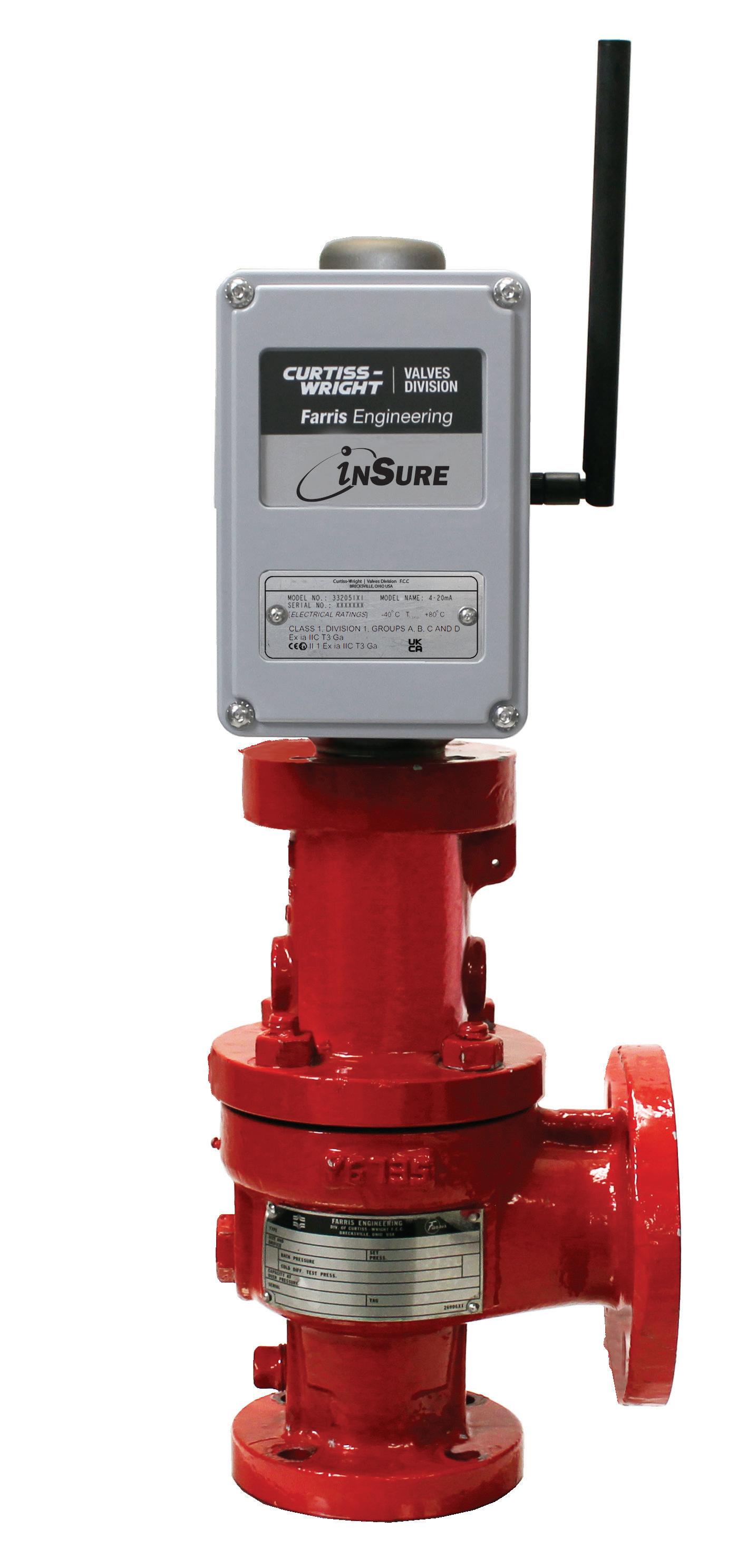
inSure Monitoring Device
Real Time Monitoring for Pressure Relief Valves
This Device provides real time monitoring for pressure relief valves. It communicates with your DCS, Distributed Control System, or through the app providing valve status, access to reporting and notification of pressure events.
•Provides communication options for mobile field & control systems
•No penetration of valve’s pressure boundary
•Stores data for discharge analysis
•Calculate flow based on valve lift
•Retrofit inSure to existing Farris Engineering 2600 Series valve
•Live Valve Data
•Network Info
•Valve Records Retention

Data also can be accessed using the inSure app via Bluetooth, iOS and Android.


© 2015 Farris Engineering Printed in U.S.A. 2/15 7500-2700 R6
NV V
The device collects and stores valve status and transfers data to the DCS via communication protocols LoRa, ISA, WirelessHart.
Signal Hill - Bakersfield - Las Vegas - Phoenix - New Castle - Tallmadge - South Point - Midland - Kingsport - Richmond - Houston
Pressure Relief Device Solutions & Services
NEW CASTLE
2680 New Butler Rd. New Castle, PA 16101
Tel: 724-368-8725
Email: sales@portersvillerd.com
RICHMOND
700 Southlake Blvd. North Chesterfield VA 23236
Tel: 804-593-2384
Email: sales@portersvillerd.com
www.portersvilleprd.com
TALLMADGE
143 S.Thomas Rd. Tallmadge, OH 44278
Tel: 330-253-4800
Email: sales@portersvilleprd.com
KINGSPORT
1551 Shipley Ferry Road
Blountville, TN 37617
Tel: 423.482.0496
Email: sales@portersvillerd.com
TALLMADGE 133 S.Thomas Rd. Tallmadge, OH 44278
Tel: 833-556-2600
Email: inventory@prddistribution.com
www.prddistribution.com
SIGNAL HILL
1500 E. Burnett St. Signal Hill, CA 90755
Tel: 562-424-8108
Email: Sales@BV-BM.comcom


SOUTH POINT
403 Technology Dr South Point, OH 45680
Tel: 740-377-0012
Email: sales@portersvilleprd.com
BAKERSFIELD
3800 Fruitvale Avenue Bakersfield, 93308
Tel: 661-589-6801
BENICIA
3195 Park Road, Benicia, CA 94510
Tel: 707-590-6688
Email: Sales@BV-BM.com
Email: Sales@BV-BM.com
www.bv-bm.com © 2024 PRD Technologies Group LLC - All Rights Reserved. 01/2024
