MODEL L76T DETAILS SPECIFICATIONS FLOWS HOW TO ORDER
MODEL L76C-UF DETAILS
SPECIFICATIONS FLOWS HOW TO ORDER
MODEL L7658A DETAILS
SPECIFICATIONS FLOWS HOW TO ORDER
MODEL L7661 DETAILS SPECIFICATIONS
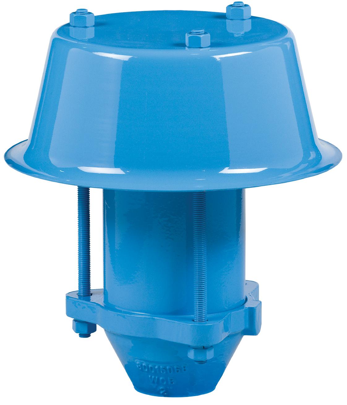
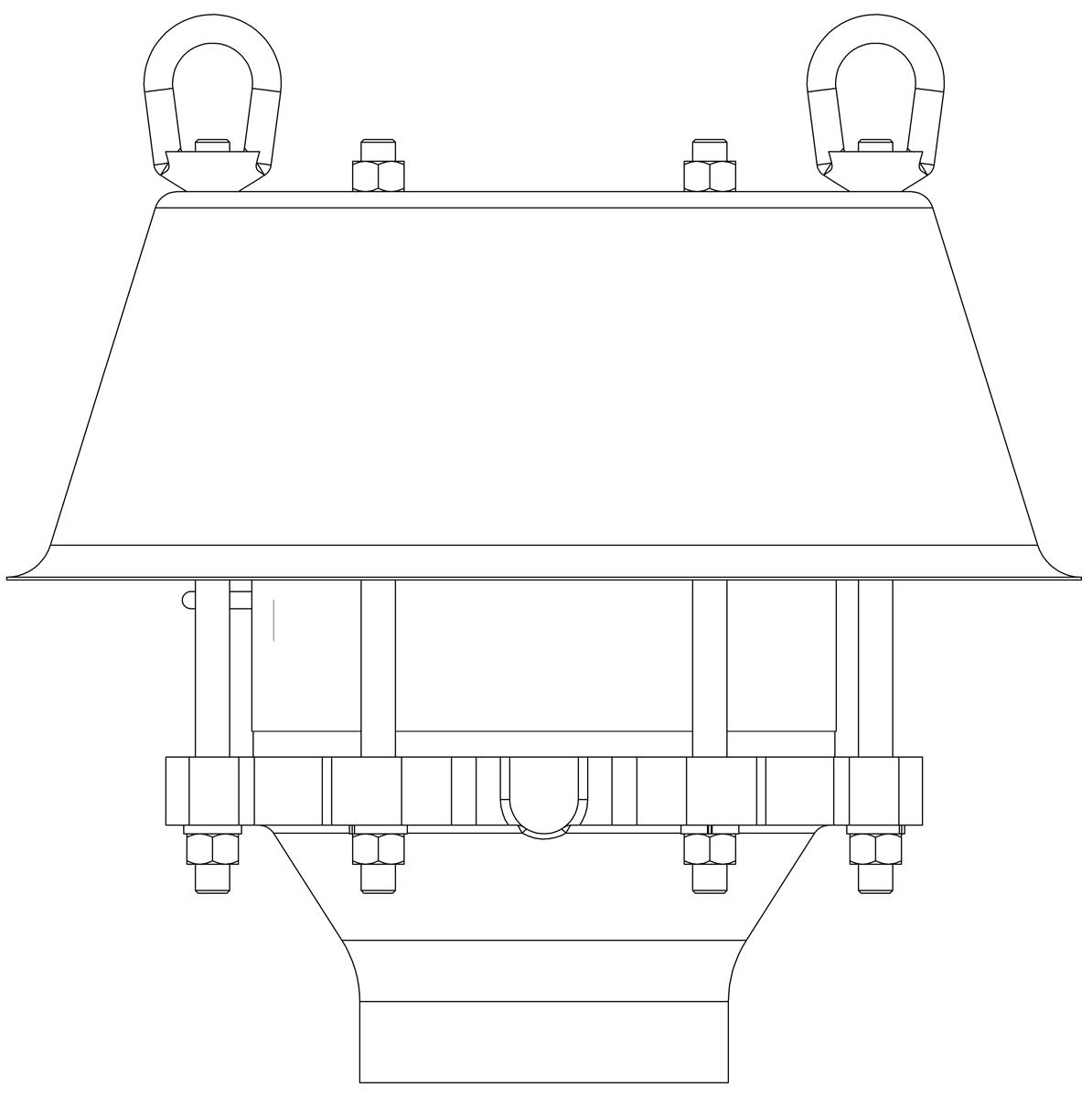
L76V-SF
The LaMOT Valve & Arrestor Model L76V-SF is an End-Of-Line Vent Stack Deflagration Flame Arrestor designed to inhibit flame propagation in gas piping systems and to protect low pressure tanks containing flammable liquids. Arrestors protect low flash point liquids from external sources of ignition. This provides increased fire protection and safety.
Technical Details
• Connection sizes: 2", 3", 4" & 6" NPT
• Housing standard material: Carbon Steel, Stainless Steel, Aluminum
• Flame element standard material: 316L Stainless Steel, Aluminum
• Operational Temperature Range -4 to 140 ºF (-20 to 60 ºC)
• Burn Time tBT 6 minutes Aluminum element, 7 minutes 316SS element
• NEC gas group D, IEC gas group IIA, MESG > 0.90 mm
Features
• Flame arrestor element geometry maximizes flame quenching capability while minimizing pressure drop
• Proven spiral-wound, crimped-ribbon flame element provides reliable flame protection
• Modular design allows easy and cost-effective flame bank maintenance
Options
• Exterior painting or coating available
• Instrument ports available
• Factory installed thermocouples for flame sensing available
L76V-SF SPECIFICATIONS
Model L76V-SF Operating Zone
The NEC and IEC are the two recognized standards for gas groupings. The NEC is used in the United States while the IEC is international in scope and widely used in Europe. Both the NEC and IEC classify gases into explosion groups based on their maximum experimental safety gap (“MESG”). Customer is responsible for ensuring product selection based on MESG.
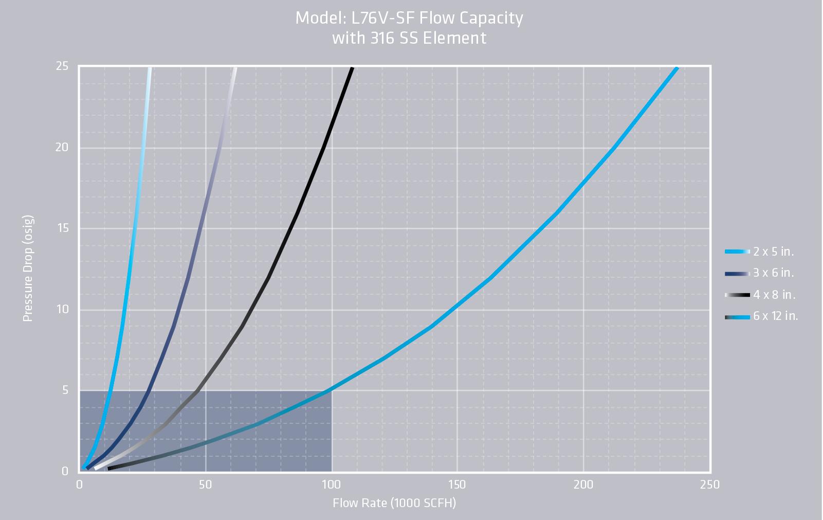
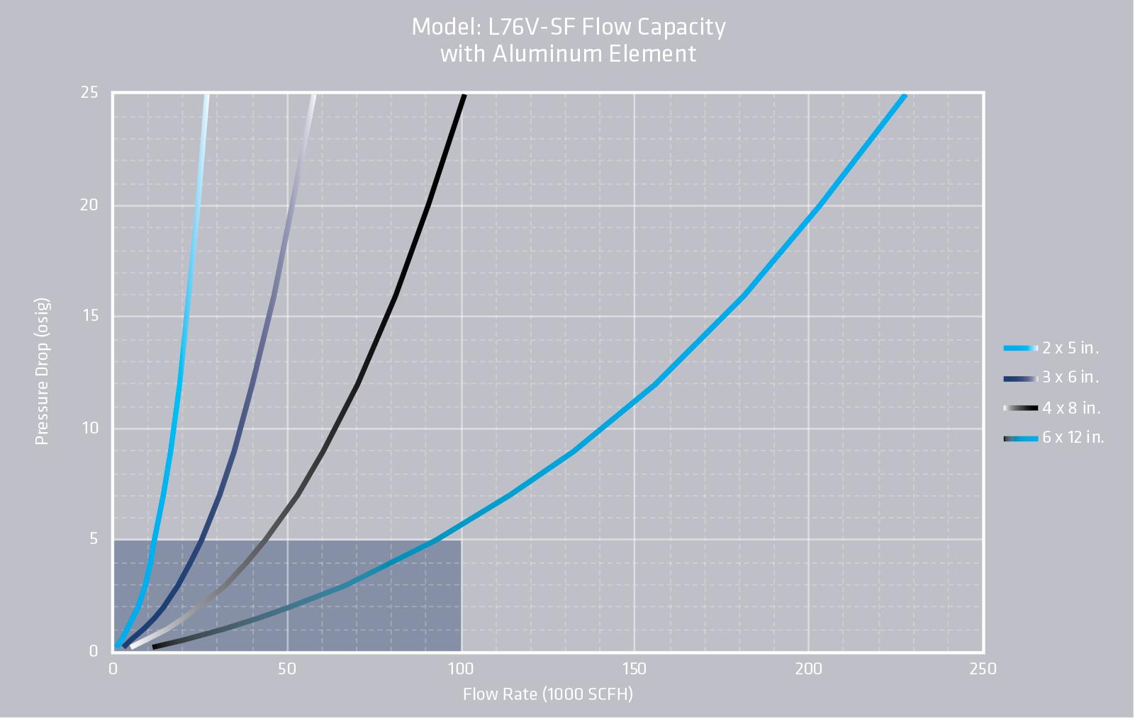
L76V-SF FLOW CAPACITY
• The test equipment, procedures, and reporting methods meet the requirements of standards API 2000/ISO 28300 and ISO 16852. The equipment, methods, and results have been reviewed and certified by TÜV SÜD.
• Flow data are for tank mounting or end of line and includes flame arrester entrance loss, exit loss and internal losses.
• Flow values based on air at 60°F venting to atmospheric pressure of 14.6959 psia.
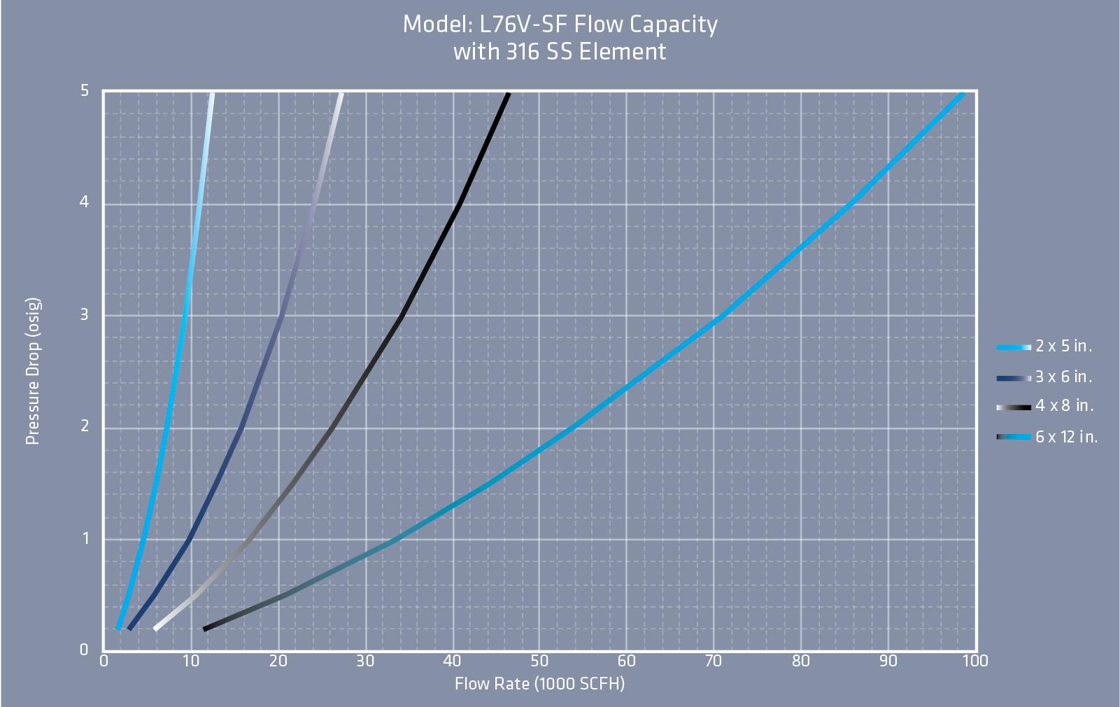
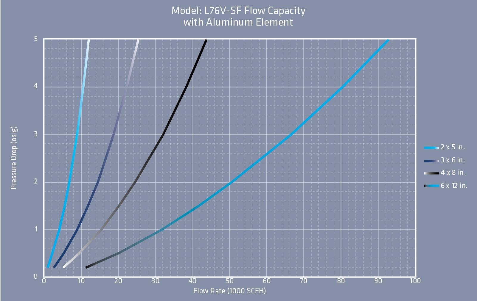
L76V-SF HOW TO ORDER
For easy ordering, select proper model numbers
Notes
Flame Element Housing & Winding Material
1 = Aluminum Housing & 316 SS Element
3 = Carbon Steel Housing & 316 SS Element
5 = 316 SS Housing & 316 SS Element
A = Aluminum Housing & Aluminum Element
C = Carbon Steel Housing & Aluminum Element
Base Material
1 = Aluminum
3 = Carbon Steel
5 = 316 Stainless Steel
• Include model number and setting when ordering
• For special options, consult factory L76V Vent Stack Threaded End-of-Line Deflagration Arrestor
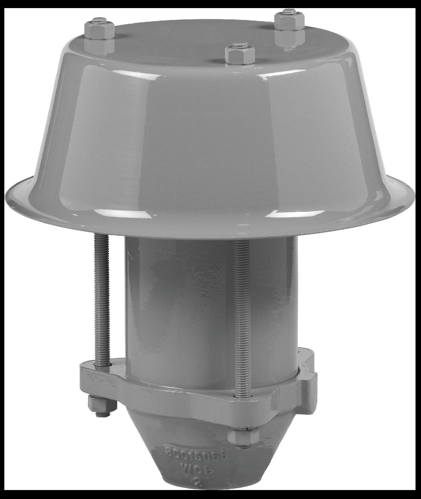
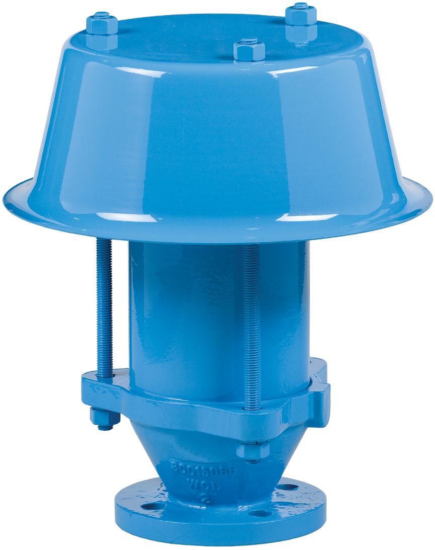
MODEL L76W-SF
The LaMOT Valve & Arrestor Model L76W-SF is an End-Of-Line Vertical Deflagration Flame Arrestor designed to inhibit flame propagation in gas piping systems and to protect low pressure tanks containing flammable liquids. Arrestors protect low flash point liquids from external sources of ignition. This provides increased fire protection and safety. LaMOT Valve & Arrestor leads the industry in arrestor reliability. Each LVA arrestor design undergoes extensive third party testing assuring the performance you expect.
Technical Details
• Connection sizes 2” through 12”
• Housing standard material: carbon steel, stainless steel, aluminum
• Flame element standard material: 316L stainless steel
• ASME standard flange drilling
• Operational Temperature Range -4 to 140 ºF (-20 to 60 ºC)
• Burn Time tBT 2 minutes
• NEC gas group D, IEC gas group IIA (MESG > 0.90 mm)
• Arrestor tested in compliance with EN ISO 16852:2010
• Vertical end of line installation application
Features
• LVA’s flame arrestor element geometry maximizes flame quenching capability while minimizing pressure drop
• Proven spiral-wound, crimped-ribbon flame element provides reliable flame protection
• Modular design allows easy and cost-effective flame bank maintenance and replacement
Options
• Exterior painting or coating available
• Instrument ports available
• Factory installed thermocouples for flame sensing available
L76W-SF SPECIFICATIONS
The NEC and IEC are the two recognized standards for gas groupings. The NEC is used in the United States while the IEC is international in scope and widely used in Europe. Both the NEC and IEC classify gases into explosion groups based on their maximum experimental safety gap (“MESG”). Customer is responsible for ensuring product selection based on MESG.
Model L76W-SF Operating Zone
L76W-SF FLOW CAPACITY
• The test equipment, procedures, and reporting methods meet the requirements of standards API 2000/ISO 28300 and ISO 16852. The equipment, methods, and results have been reviewed and certified by TÜV SÜD.
• Flow data are in-line mounting an does not include entrance or exit losses
• Flow
parameters based on EN
L76W-SF FLOW CAPACITY
• The test equipment, procedures, and reporting methods meet the requirements of standards API 2000/ISO 28300 and ISO 16852. The equipment, methods, and results have been reviewed and certified by TÜV SÜD.
• Flow data are in-line mounting an does not include entrance or exit losses
• Flow values based on air at
L76W-SF HOW TO ORDER
For easy ordering, select proper model numbers
L76W Weatherhood
Notes
tested in accordance with ISO 16852
• Include model number and setting when ordering
• For special options, consult factory
Example
Flame Element Housing & Winding Material 1 = Aluminum Housing & 316 SS Element
Indicates a LaMOT Model L76W, 2” 150# ASME Bolted Connection , with 5” Housing Size, Carbon Steel Bases, Carbon Steel Housing, with 316 SS Flame Element, and no other options.
MODEL L76L
The LaMOT Valve & Arrestor Model L76L is designed to inhibit flame propagation in gas piping systems and to protect low pressure tanks containing flammable liquids. Arrestors protect low flash point liquids from external sources of ignition, providing increased fire protection and safety.
Technical Details
• Connection sizes: 1” and 2” NPT
• Housing standard material: 1” Carbon Steel, Aluminum
• 2” Carbon Steel
• Flame element standard material: Stainless Steel
• Operational Temperature Range: -4 to 140 ºF (-20 to 60 ºC)
• Gas Group: NEC D; IEC IIA (MESG > 0.90 mm)
• Burn Time: tBT 20 minutes at Atmospheric Pressure
Features
• Flame arrestor element geometry maximizes flame quenching capability while minimizing pressure drop
• Spiral-wound, crimped-ribbon flame element
• Bi-directional with respect to flow and ignition source
Options
• Exterior painting or coating
L76L SPECIFICATIONS
Specifications subject to change without notice. Certified dimensions available upon request.
Pneumatic tested to 15 psig as standard.
The NEC and IEC are the two recognized standards for gas groupings. The NEC is used in the United States while the IEC is international in scope and widely used in Europe. Both the NEC and IEC classify gases into explosion groups based on their maximum experimental safety gap (“MESG”). Customer is responsible for ensuring product selection based on MESG.
Model L76L Operating Zone
L76L SPECIFICATIONS
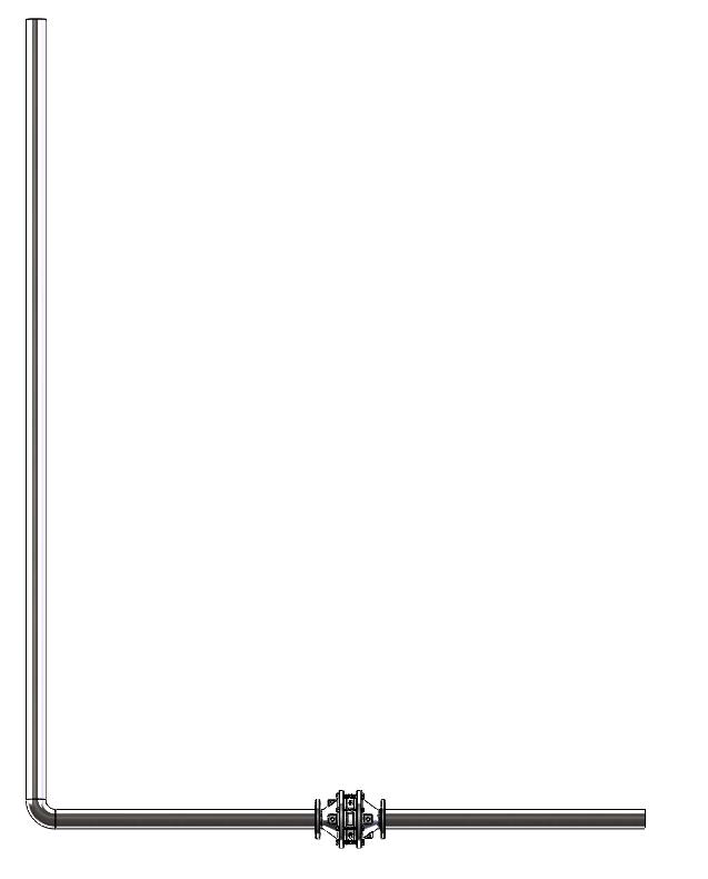
For an arrestor to be properly applied, all the requirements for one of the two following configuration scenarios must be met.
Configuration End Condition Gas Group Maximum Pipe Length from Ignition Source to Flame Arrestor
Straight Pipe Closed D (IIA)50 pipe diameters
18.9 (1.3) None 20 minutes-4 to 140 (-20 to 60)
20 ft with Bend Open D (IIA)20 ft (ignition source - max of 15 ft - bend - max of 5 ft - arrestor) 15.9 (1.1)One 90 degree20 minutes-4 to 140 (-20 to 60)
Straight Pipe, Closed End Configuration, is designed and tested according to EN ISO 16852:2016, except for:
1. The short time burn test was conducted at atmospheric pressure, for a time period extending past 1 minute.
*No additional bends or restrictions are allowed.
Model L76L-UF, 20 ft with Bend, Open End Configuration, is designed and tested according to EN ISO 16852:2016, except for:
1. The piping on the unprotected side, consisted of ignition source, 15 ft of straight pipe, one 90 degree bend, 5 ft of straight pipe, then the arrester.
2. The short time burn test was conducted at atmospheric pressure, for a time period extending past 1 minute.
3. Tested with a thin film on the end, to simulate an open-ended piping configuration.
*No additional bends or restrictions are allowed.
20ft with bend Ignition Source
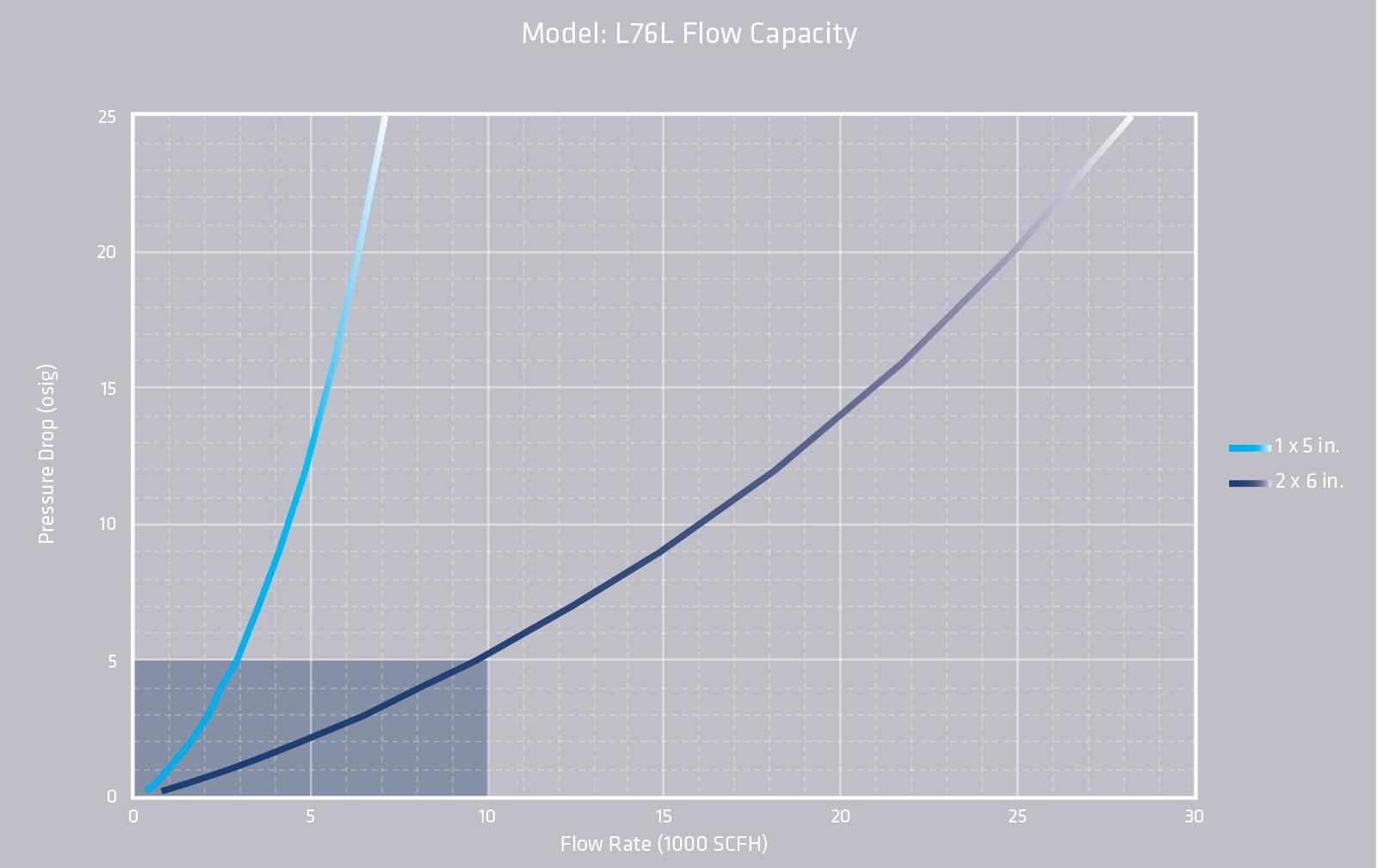
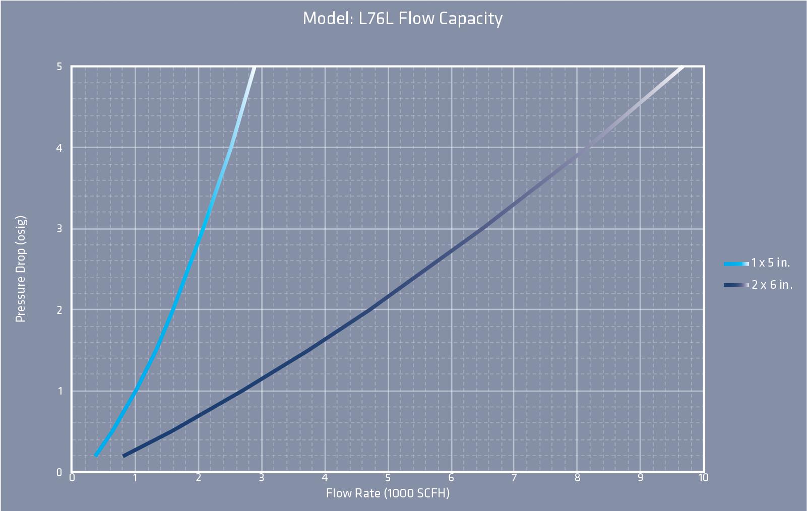
L76L FLOW CAPACITY
• The test equipment, procedures, and reporting methods utilized by LaMOT Valve & Arrestor meet the requirements of standards API 2000/ISO 28300 and ISO 16852. The equipment, methods and results have been reviews and certified by TÜV SÜD.
• Flow data are for in-line mounting and does not include entrance losses or exit losses.
• Flow values based on air at 60°F venting to atmospheric pressure of 14.6959 psia
L76L HOW TO ORDER
For easy ordering, select proper model numbers
Notes
• Include model number and setting when ordering
• For special options, consult factory *Only available with 2” connection
Indicates a 2" Model L76L with a 6” element, Carbon Steel Housing, Carbon Steel Base, Threaded outlet, and no other options.
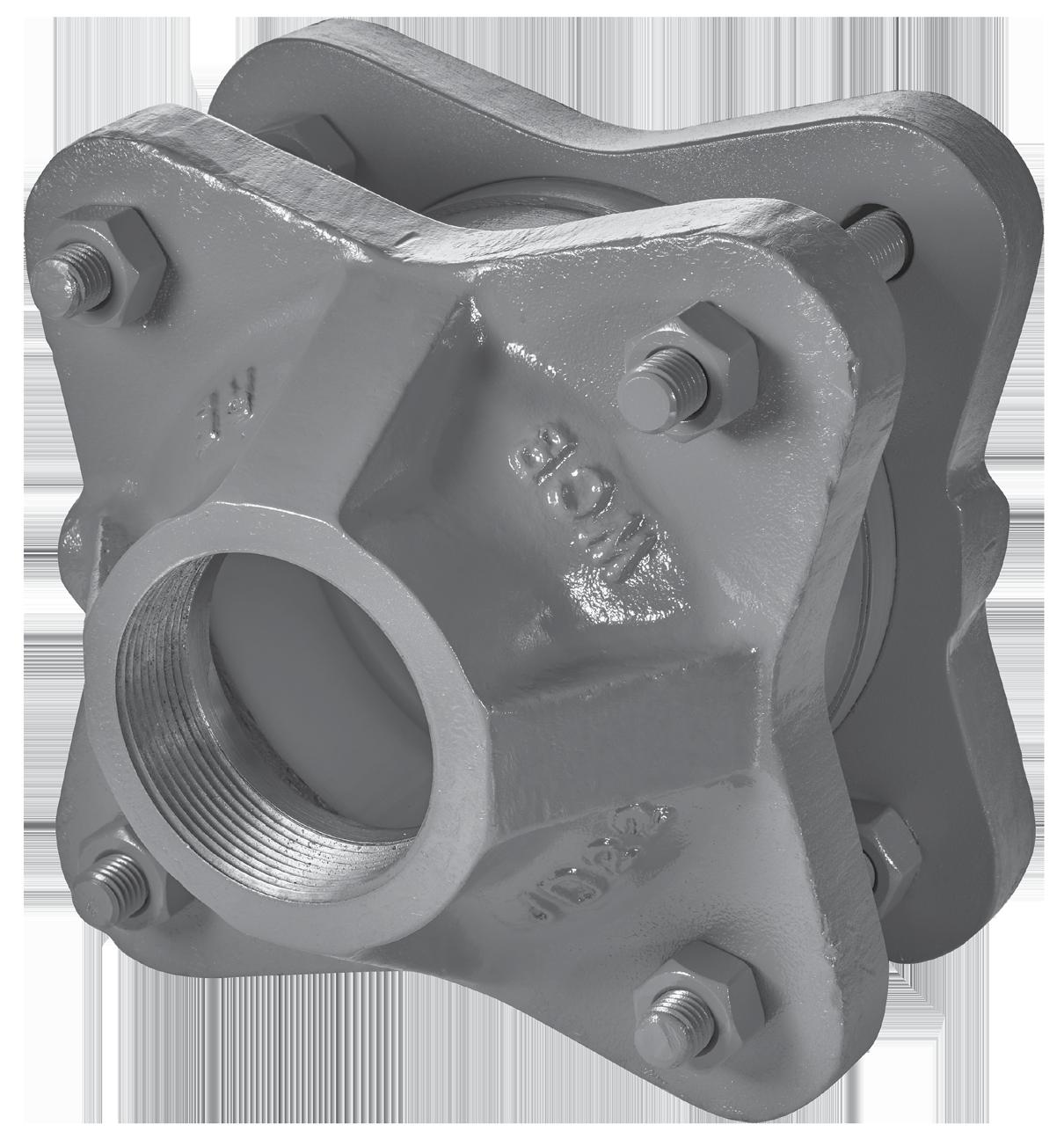
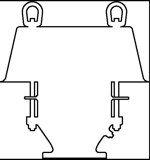
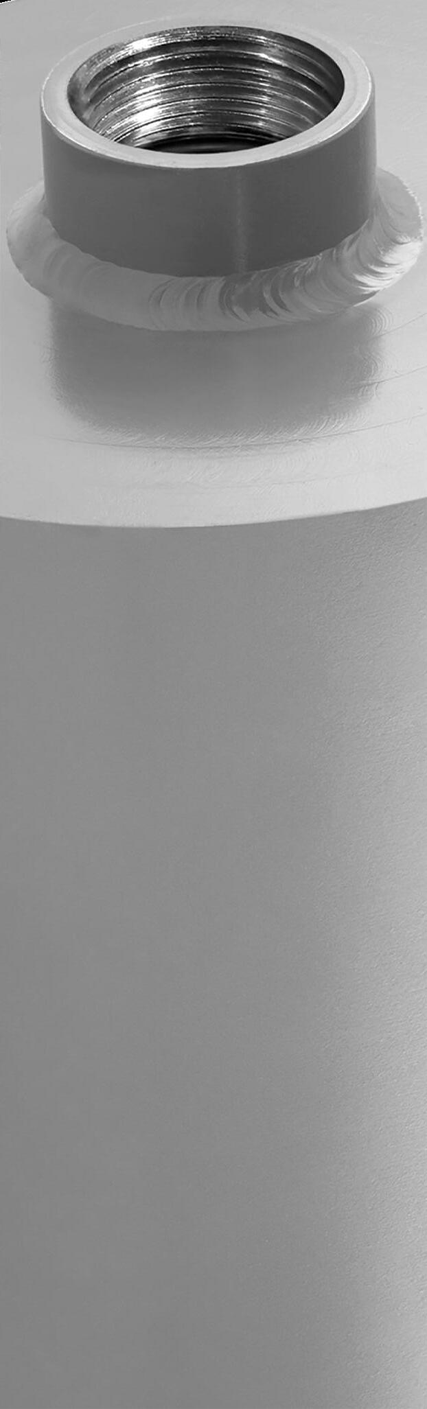
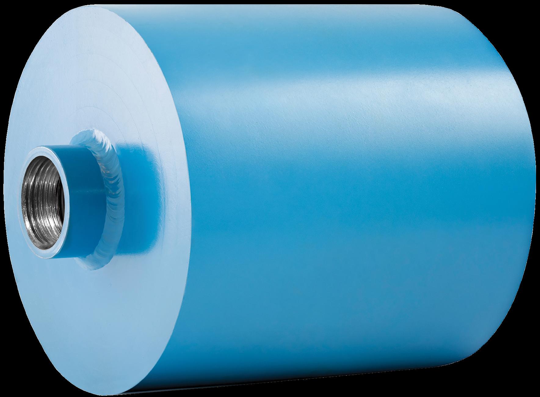
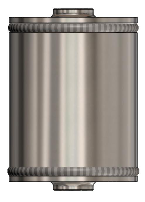
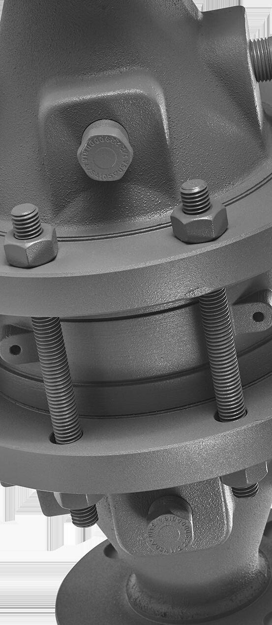
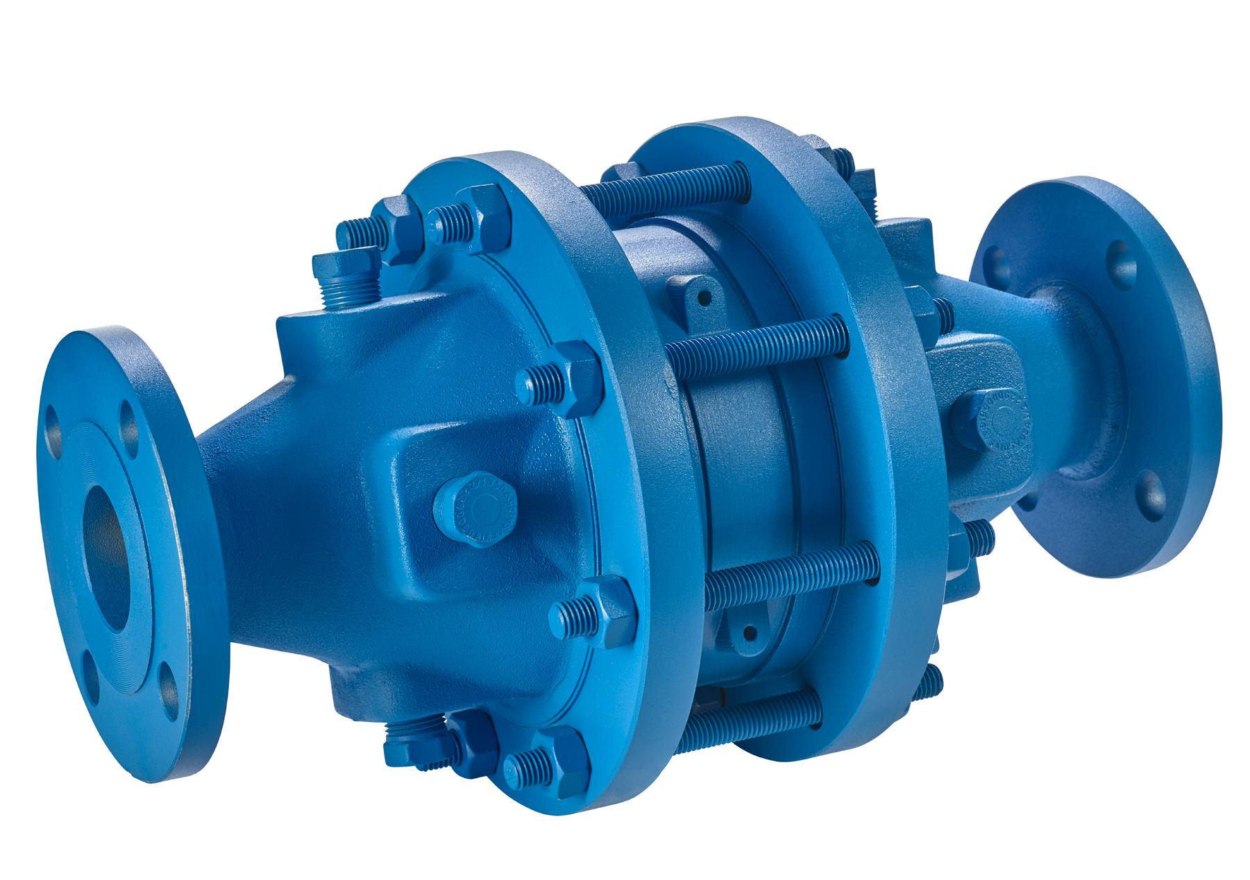
MODEL L76T
The LaMOT Valve & Arrestor Model L76T-UF is designed to inhibit flame propagation in gas piping systems and to protect low pressure tanks containing flammable liquids. Arrestors protect low flash point liquids from external sources of ignition. This provides increased fire protection and safety.
Technical Details
• Connection Sizes: 2”, 3” and 4” NPT
• Housing standard material: carbon steel, 316SS
• Bases standard material: carbon steel
• Flame element standard material: stainless steel
• Operational Temperature Range: -4 to 140 ºF (-20 to 60 ºC)
• Gas Group: NEC D; IEC IIA (MESG > 0.90 mm)
• Maximum Operational Pressure: (see charts and IOM)
• Burn Time: tBT 2.5 minutes or better at Atmospheric Pressure (see charts and IOM)
• Bi-directional with respect to flow and ignition source
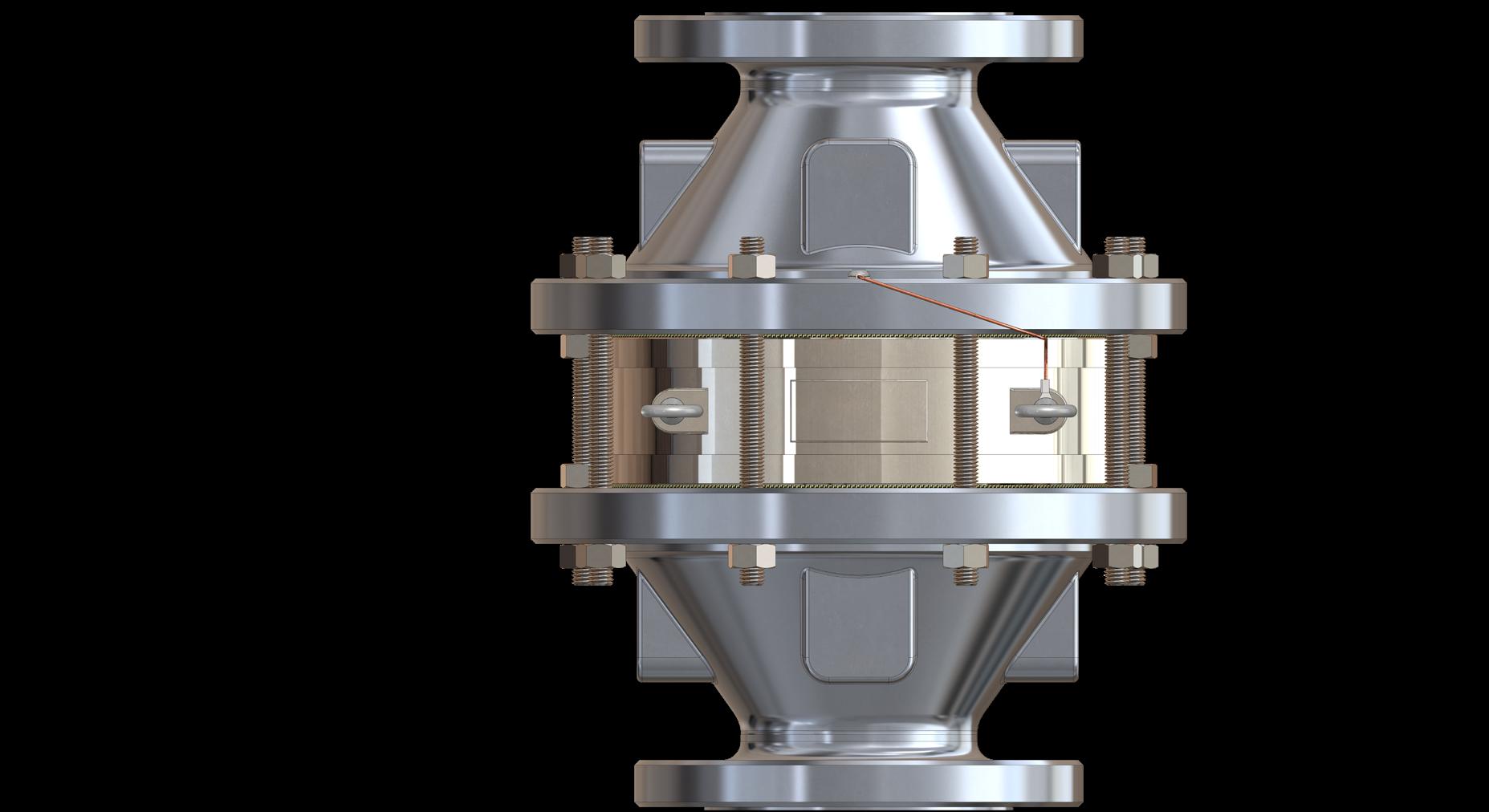
Features & Benefits
• Flame arrestor element geometry maximized flame quenching capability while minimizing pressure drop
• Removable element housing for ease of maintenance
• Spiral-wound, crimped ribbon flame element
• Flame elements made standard with premium 316SS material
Options
• Exterior painting or coating available
• Drains and instrumentation ports available
• Factory installed thermocouples for flame sensing available
Pneumatic leak tested to 15 psig as standard..
L76T SPECIFICATIONS
The NEC and IEC are the two recognized standards for gas groupings. The NEC is used in the United States while the IEC is international in scope and widely used in Europe. Both the NEC and IEC classify gases into explosion groups based on their maximum experimental safety gap (“MESG”). Customer is responsible for ensuring product selection based on MESG.
Model L76T Operating Zone
L76T SPECIFICATIONS
For an arrestor to be properly applied, all the requirements for one of the two following configuration scenarios must be met.
1)Straight Pipe, Closed End Configuration:
Gas GroupEnd ConditionMaximum Pipe Length from Ignition Source to Flame
D (IIA)Closed End50 pipe diameters 18.8 psia (1.3 bara) or better, see IOM
Model L76T-UF, Straight Pipe, Closed End Configuration, is designed and tested according to EN ISO 16852:2016, except for: 1. The short time burn test was conducted at atmospheric pressure, for a time period extending past 1 minute. *No additional bends or restrictions are allowed.
D (IIA)Open End 20 ft (ignition source - max of 15 ft - bend - max of 5 ft - arrestor) 15.5 psia (1.07 bara) or better, see IOM One 90 Degree2.5 minutes or better, see IOM -4 to 140 (-20 to 60)
Model L76T-UF, 20 ft with Bend, Open End Configuration, is designed and tested according to EN ISO 16852:2016, except for:
1. The piping on the unprotected side, consisted of ignition source, 15 ft of straight pipe, one 90 degree bend, 5 ft of straight pipe, then the arrester.
2. The short time burn test was conducted at atmospheric pressure, for a time period extending past 1 minute.
*No additional bends or restrictions are allowed.
**See below 20 ft with bend diagram
Figure 2: 20FT with bend, Allowable Installation Configuration
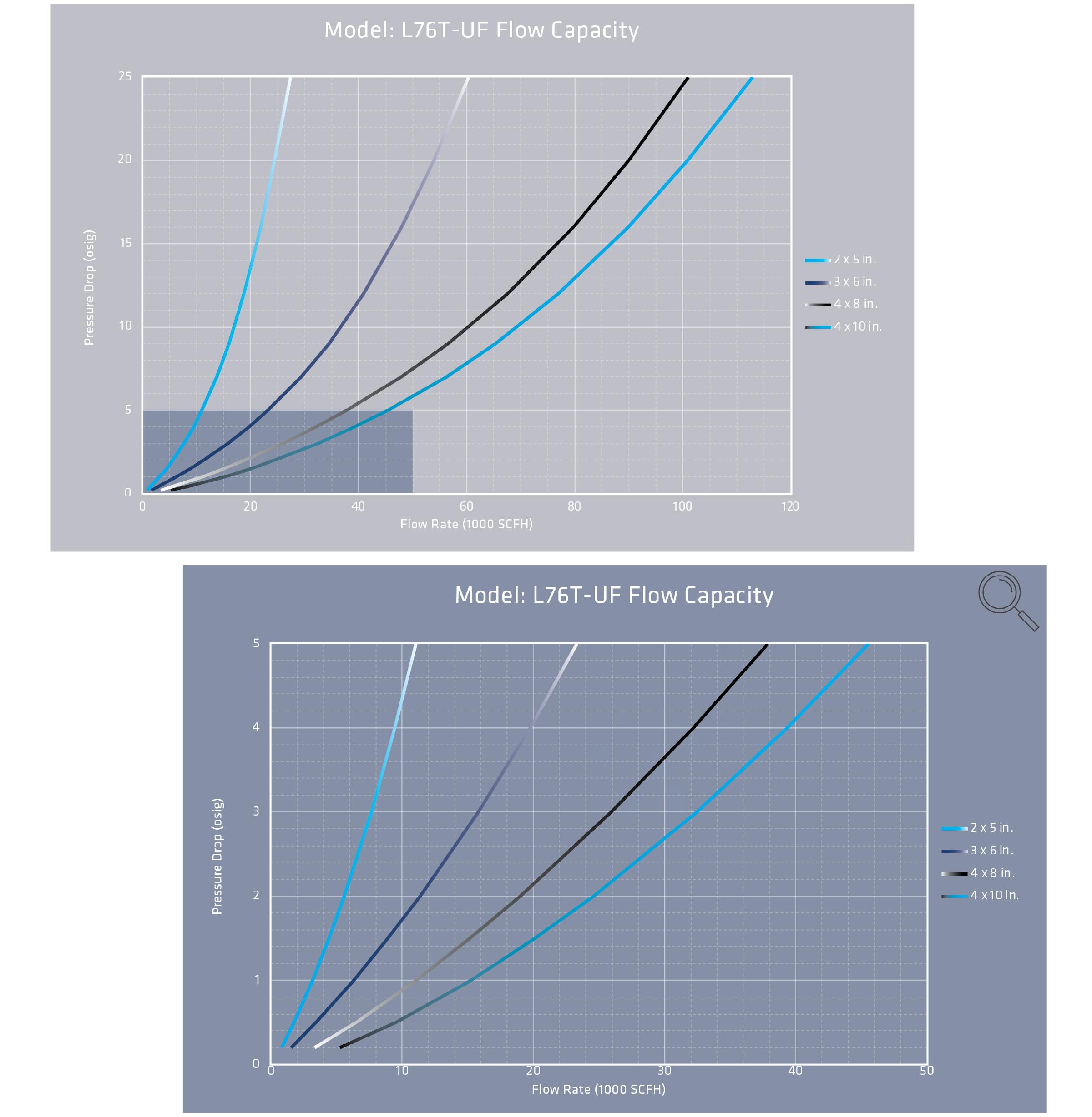
L76T FLOW CAPACITY
• The test equipment, procedures, and reporting methods utilized by Groth Corporation meet the requirements of standards API 2000/ISO 28300 and ISO 16852. The equipment, methods, and results have been reviewed and certified by TÜV SÜD.
• Flow data are for in-line mounting and does not include entrance losses or exit losses.
• Flow values based on air at 60°F venting to atmospheric pressure of 14.6959 psia
L76T HOW TO ORDER
For easy ordering, select proper model numbers
Notes
• Include model number and setting when ordering
• For special options, consult factory
Indicates a 2" x 5" Model L76T with carbon steel base, carbon steel housing, threaded inlet/outlet, and no other options.
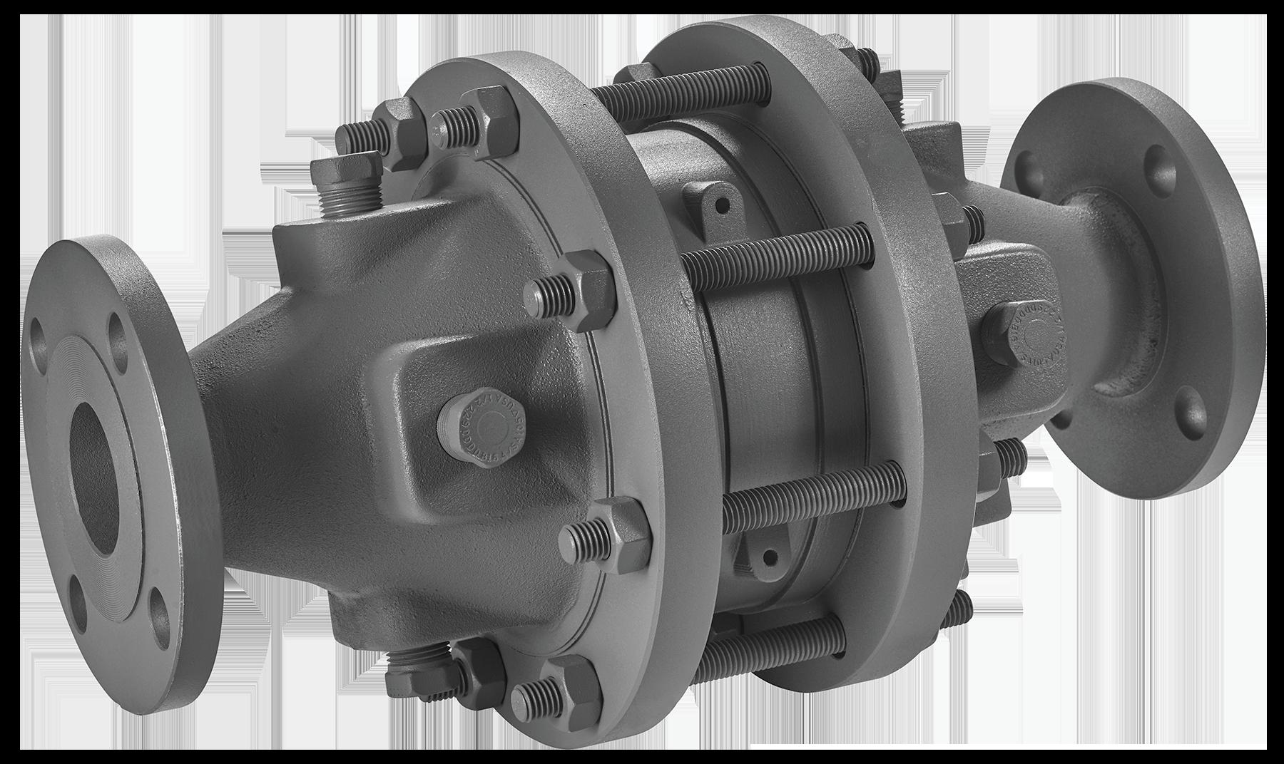
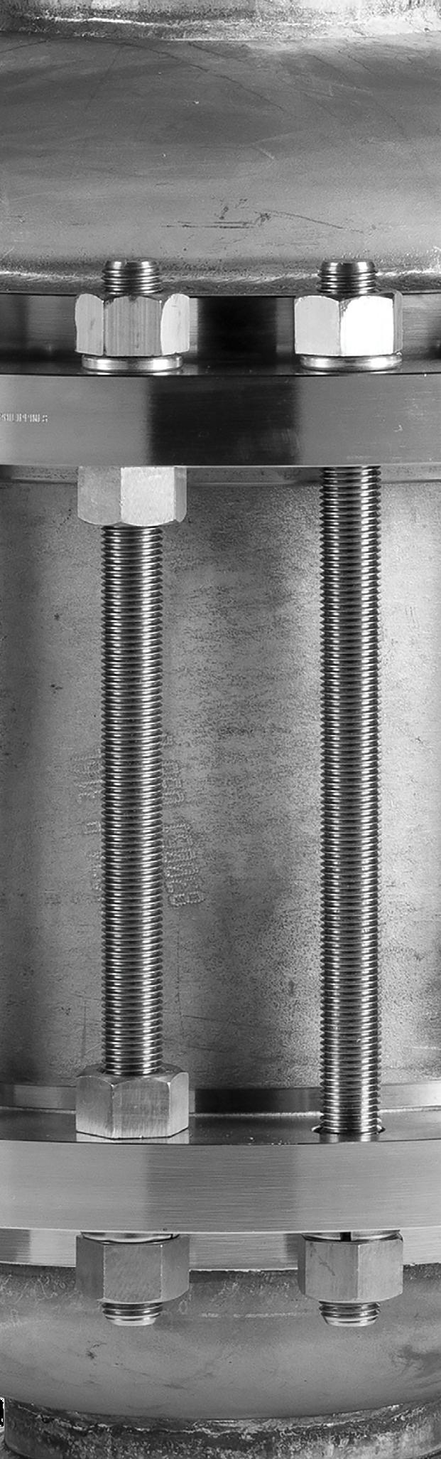
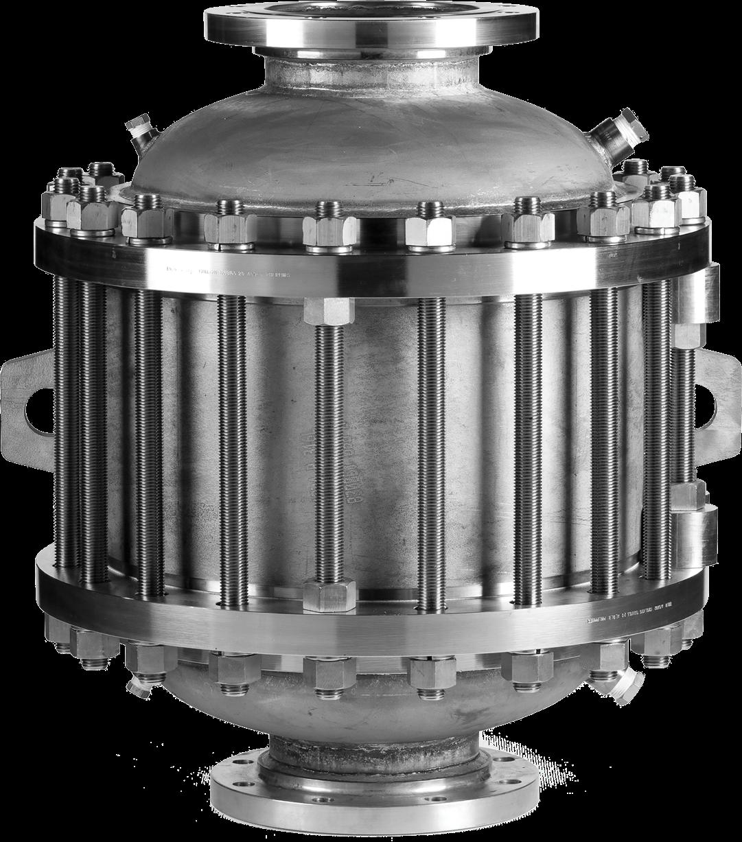
MODEL L76C-UF
The LaMOT Valve and Arrestor Model L76C-UF is a Deflagration Flame Arrestor designed to inhibit flame propagation in gas piping systems and to protect low pressure tanks containing flammable liquids. Arrestors protect low flash point liquids from external sources of ignition providing increased fire protection and safety.
Technical Details
• Connection Sizes: 2” through 12” 150# ASME Flanged Connection
• Housing standard material: Carbon Steel, Stainless Steel
The NEC and IEC are the two recognized standards for gas groupings. The NEC is used in the United States while the IEC is international in scope and widely used in Europe. Both the NEC and IEC classify gases into explosion groups based on their maximum experimental safety gap (“MESG”). Customer is responsible for ensuring product selection based on MESG.
L76C-UF SPECIFICATIONS
For an arrestor to be properly applied, all the requirements for one of the two following configuration scenarios must be met:
1)Straight Pipe, Closed End Configuration:
2” x 6” thru 12” x 28”
Model L76C-UF, Straight Pipe, Closed End Configuration, is designed and tested according to EN ISO 16852:2016, except for: 1. The short time burn test was conducted at atmospheric pressure, for a time period extending past 1 minute. *No additional bends or restrictions are allowed.
2)Configuration with Bend, Open End Configuration: Connection Size x Housing Size
Source to Flame Arrestor
2” x 6” thru 4” x 10”
End
≥ 0.90mm]
6” x 16” IIA (D) [MESG
Model L76C-UF, Configuration with Bend, Open End Configuration, is designed and tested according to EN ISO 16852:2016, except for:
1. The piping on the unprotected side, consisted of ignition source, “A” ft of straight pipe, one 90 degree bend, “B” ft of straight pipe, then the arrester.
2. The short time burn test was conducted at atmospheric pressure, for a time period extending past 1 minute.
*No additional bends or restrictions are allowed. Bends and flow restrictions can cause additional turbulence, which can increase the intensity of the flame propagation; potentially compromising the performance of the flame arrestor.
Figure 2: Configuration with Bend, Allowable Installation Configuration
Ignition Source
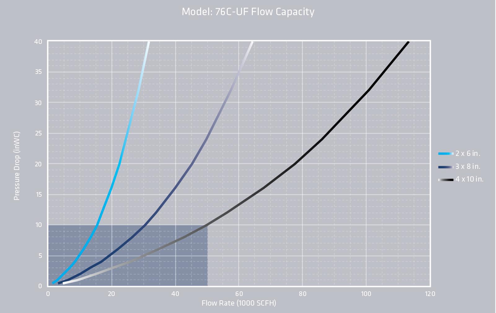
L76C-UF FLOW CAPACITY
The test equipment, procedures, and reporting methods utilized by Groth Corporation are based upon the standards API 2000/ISO 28300 and ISO 16852. The equipment, procedures, and methods have been reviewed and certified by TÜV SÜD.
Flow data are for in-line mounting and does not include entrance losses or exit losses.
Flow values based on air at 60°F venting to atmospheric pressure of 14.6959 psia.
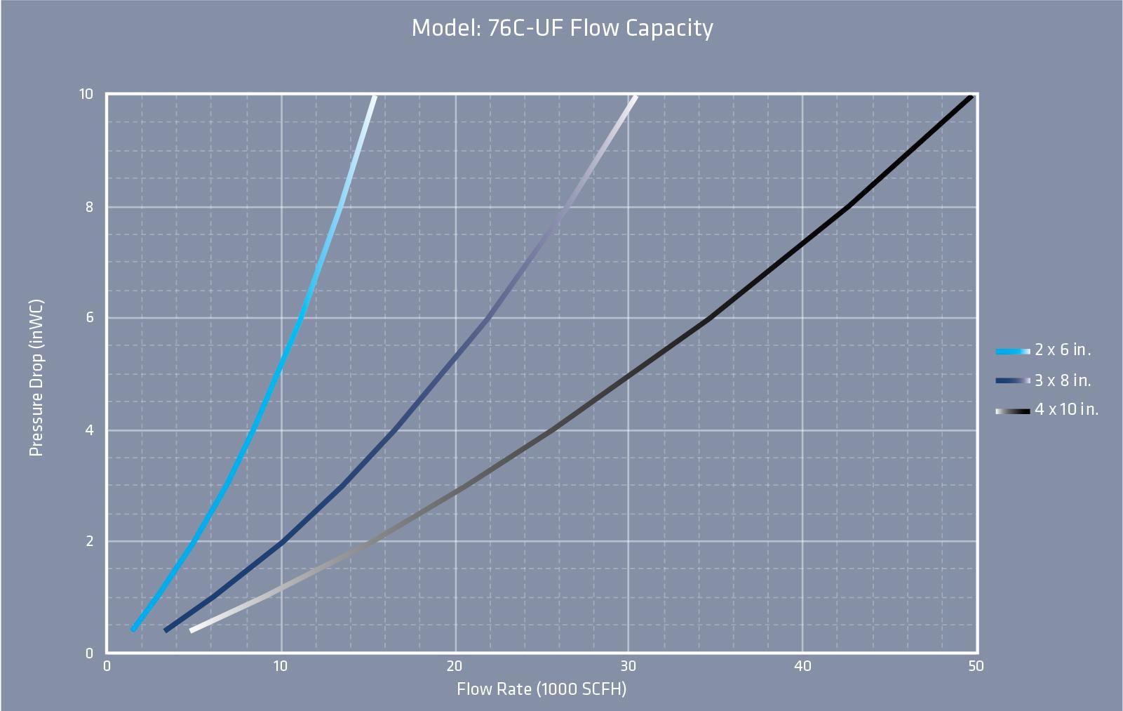
L76C-UF FLOW CAPACITY
The test equipment, procedures, and reporting methods utilized by Groth Corporation are based upon the standards API 2000/ISO 28300 and ISO 16852 The equipment, procedures, and methods have been reviewed and certified by TÜV SÜD.
Flow data are for in-line mounting and does not include entrance losses or exit losses.
Flow values based on air at 60°F venting to atmospheric pressure of 14.6959 psia.
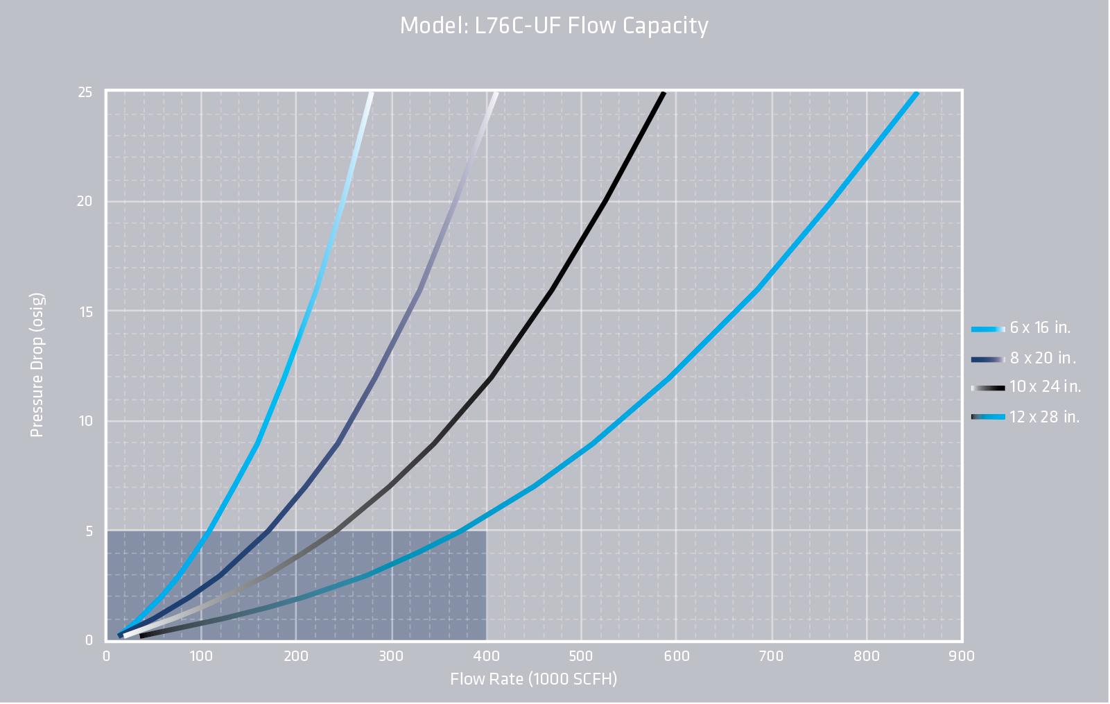
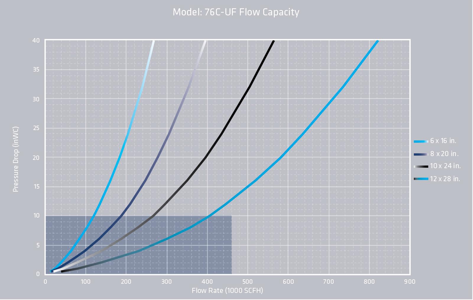
L76C-UF FLOW CAPACITY
Model: L76C-UF Flow Capacity
Model: L76C-UF Flow Capacity
The test equipment, procedures, and reporting methods utilized by Groth Corporation are based upon the standards API 2000/ISO 28300 and ISO 16852. The equipment, procedures, and methods have been reviewed and certified by TÜV SÜD.
Flow data are for in-line mounting and does not include entrance losses or exit losses.
Flow values based on air at 60°F venting to atmospheric pressure of 14.6959 psia.
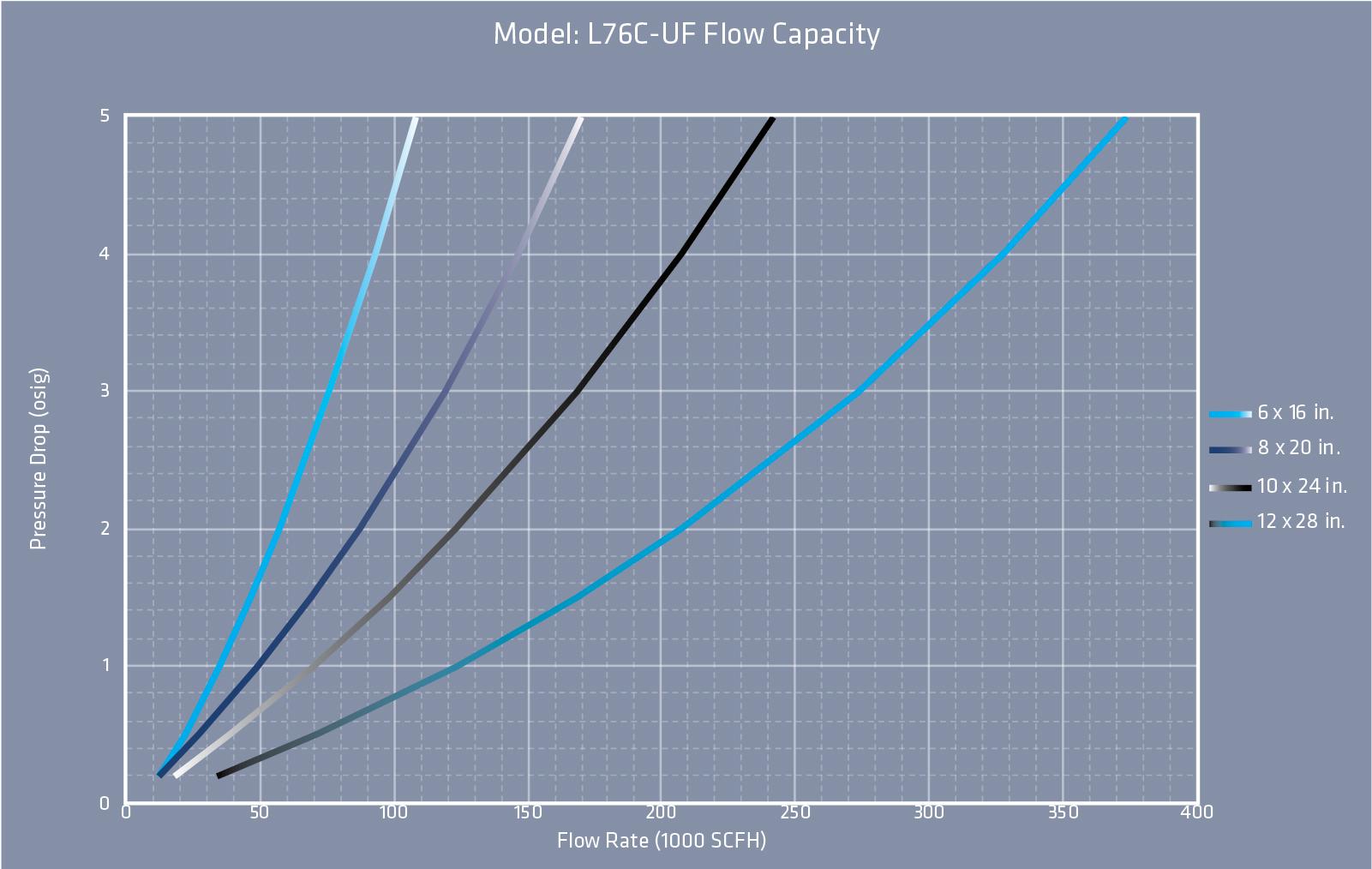
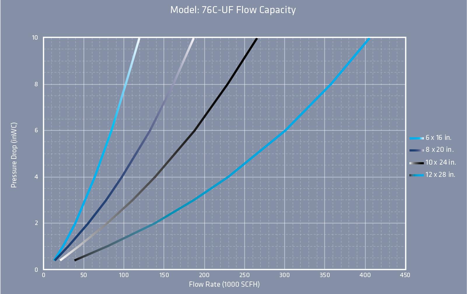
L76C-UF FLOW CAPACITY
Model: L76C-UF Flow Capacity
Model: L76C-UF Flow Capacity
The test equipment, procedures, and reporting methods utilized by Groth Corporation are based upon the standards API 2000/ISO 28300 and ISO 16852 The equipment, procedures, and methods have been reviewed and certified by TÜV SÜD.
Flow data are for in-line mounting and does not include entrance losses or exit losses.
Flow values based on air at 60°F venting to atmospheric pressure of 14.6959 psia.
L76C-UF HOW TO ORDER
For easy ordering, select proper model numbers
L76C 150# ASME
Bolted Connection UF Upstream Deflagration
Notes
• Include model number and setting when ordering
• For special options, consult factory
Housing & Winding Material
3 = Carbon Steel Housing & 316 SS Element
5 = 316 SS Housing & 316 SS Element
Base Material
1 = Aluminum*
3 = Carbon Steel
5 = Stainless Steel
• *Aluminum base material is only available in connection sizes 2” through 6”
Example
Indicates a LaMOT Model L76C-UF, Upstream Configuration, 2” ASME 150# Bolted Connection, with a 6” Housing Size, Carbon Steel Bases, Carbon Steel Housing with 316 SS element, and no other options.
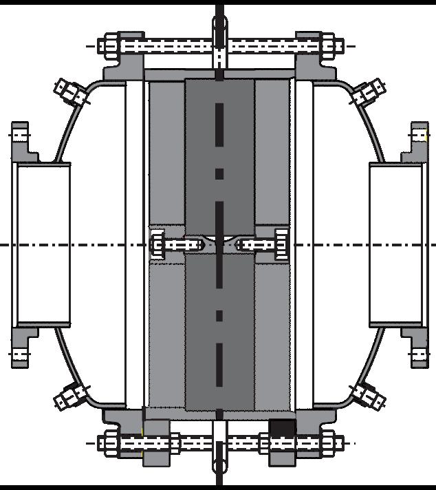
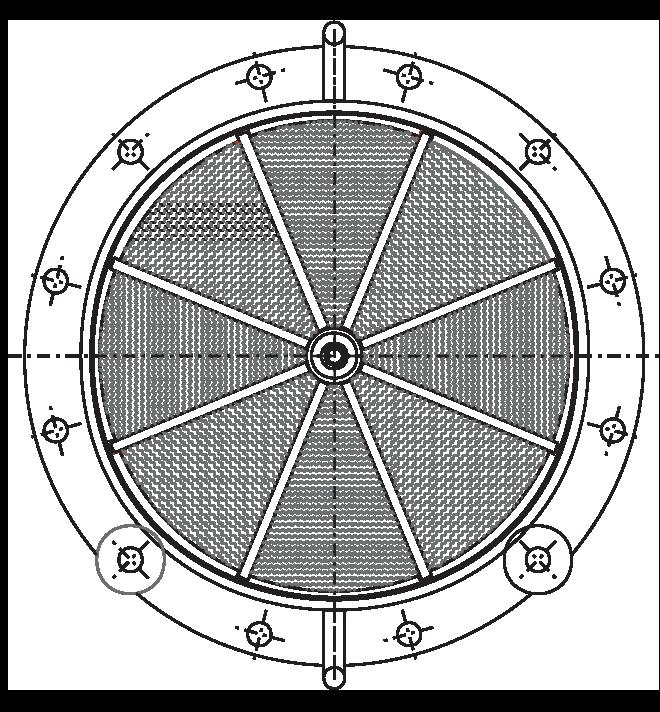
MODEL L7658A
The LaMOT Valve & Arrestor Model L7658A model inhibits flame propagation in gas piping systems. It is ideal for protecting liquid storage tanks containing NEC Group D (IEC Class IIA) gases with a maximum experimental safe gap equal to or greater than 0.90 mm.
Technical Details
• Connection Size: 2”x 5” through 6”x 12”
• Vertical or horizontal installation
• In-line or end-of-line deflagrations
• Unstable detonations
• Burn Time tBT 10 minutes
• Bi-directional with respect to flow and ignition source
• Housing standard material: Carbon Steel or Stainless Steel
• Flame element standard material: Stainless Steel
• Pressure: Maximum Operational pressure 15.7 psia (1.08 bara)
• Operational Temperature Range: -4 to 140 °F (-20 to 60 °C)
Features
• Elements are easily removed in-line for cleaning and maintenance and are economical to replace if necessary
• Low pressure drop with multiple element sizes available for each flange size
Options
• Factory installed thermocouples for flame sensing
• Other housing materials available
• Sensor ports
• Large inspection and cleaning ports
• Swing bolts for fast element removal
L7658A SPECIFICATIONS
Specifications subject to change without notice. Certified dimensions available upon request Larger sizes available on special application All units with ANSI 150 RF flanges standard (other flange drillings available).
Model L7658A Operating Zone
The NEC and IEC are the two recognized standards for gas groupings. The NEC is used in the United States while the IEC is international in scope and widely used in Europe. Both the NEC and IEC classify gases into explosion groups based on their maximum experimental safety gap (“MESG”). Customer is responsible for ensuring product selection based on MESG.
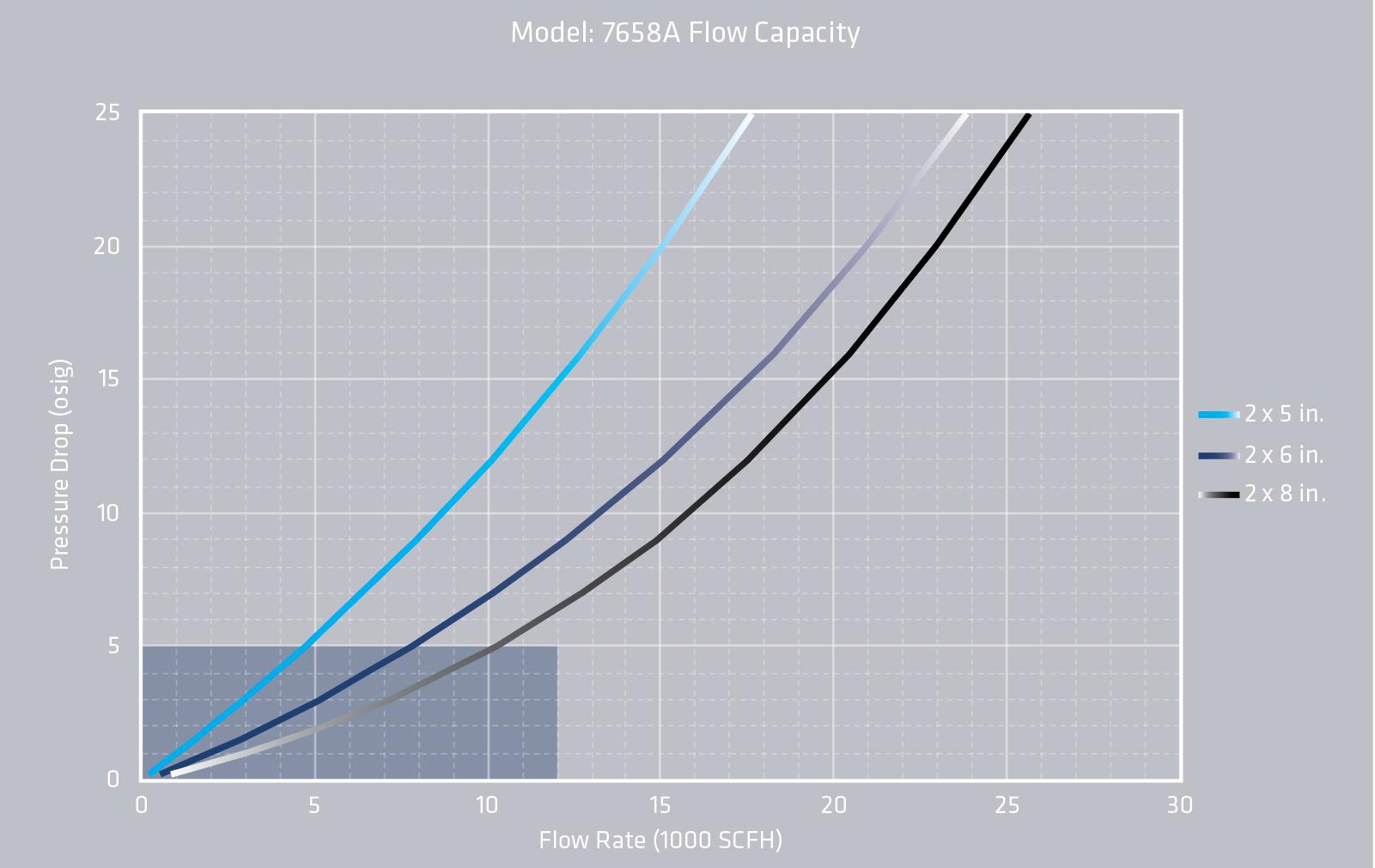
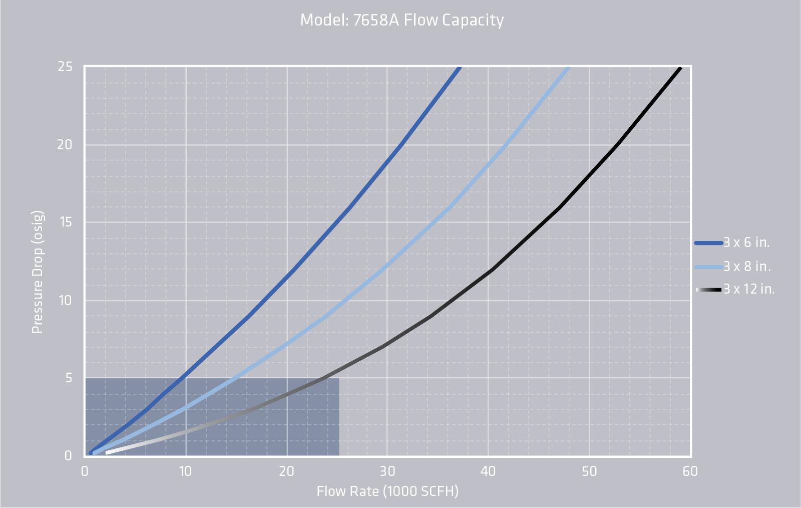
L7658A FLOW CAPACITY
Model: L7658A Flow Capacity
Model: L7658A Flow Capacity
• The test equipment, procedures, and reporting methods meet the requirements of standards API 2000/ISO 28300 and ISO 16852. The equipment, methods, and results have been reviewed and certified by TÜV SÜD
• Flow data are for in-line mounting and does not include entrance losses or exit losses
• Flow values based on air at 60°F venting to atmospheric pressure of 14.6959 psia
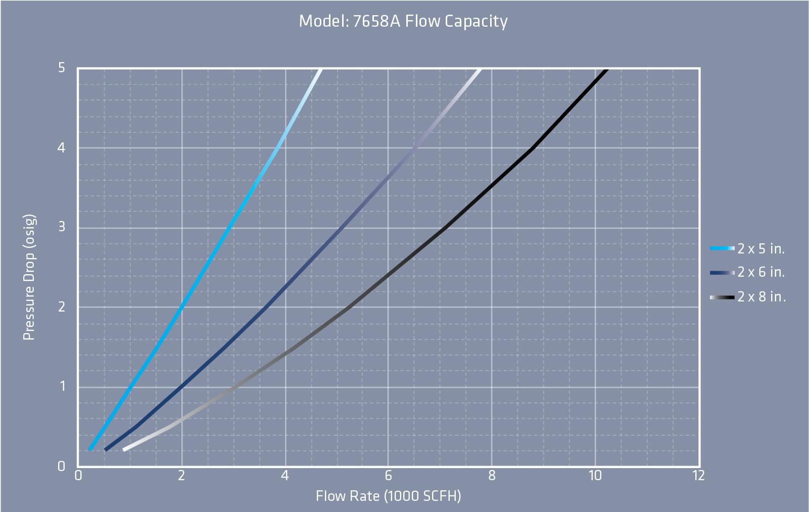
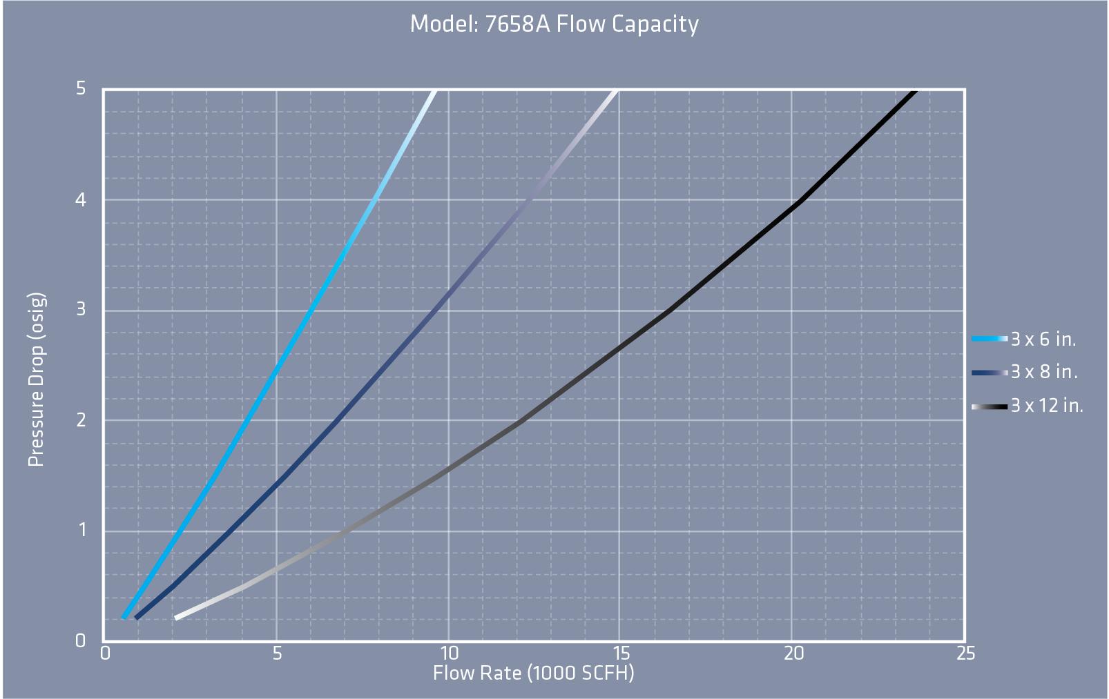
L7658A FLOW CAPACITY
• The test equipment, procedures, and reporting methods meet the requirements of standards API 2000/ISO 28300 and ISO 16852. The equipment, methods, and results have been reviewed and certified by TÜV SÜD
• Flow data are for in-line mounting and does not include entrance losses or exit losses
• Flow values based on air at 60°F venting to atmospheric pressure of 14.6959 psia
Model: L7658A Flow Capacity
Model: L7658A Flow Capacity
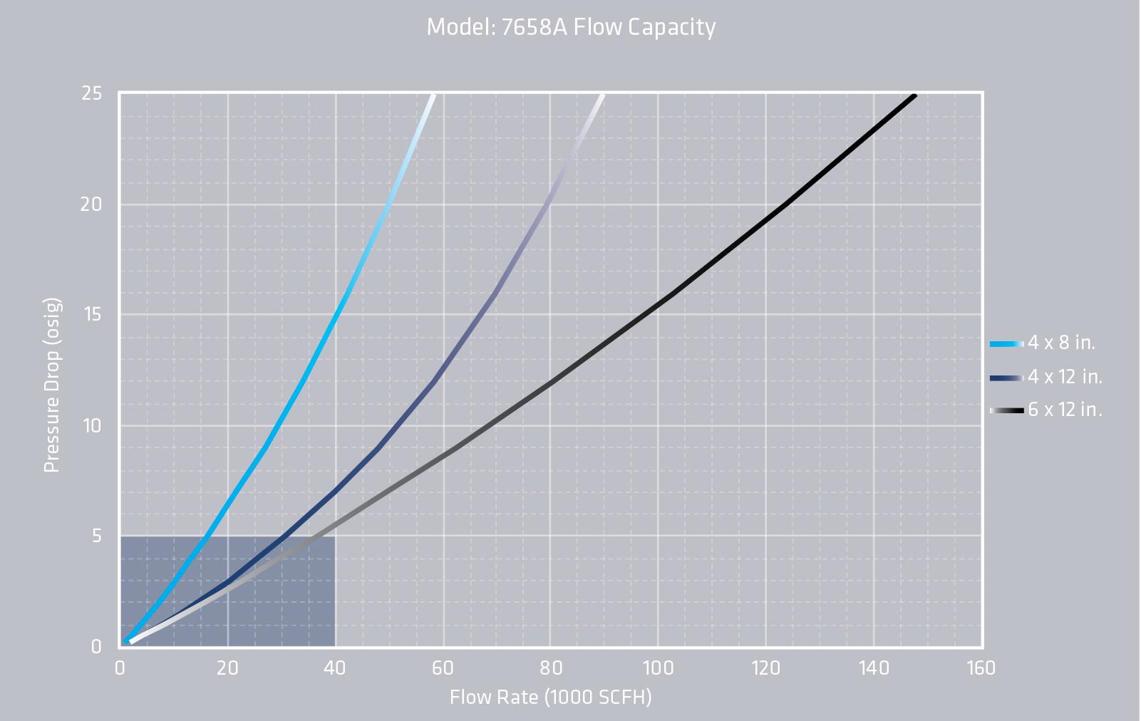
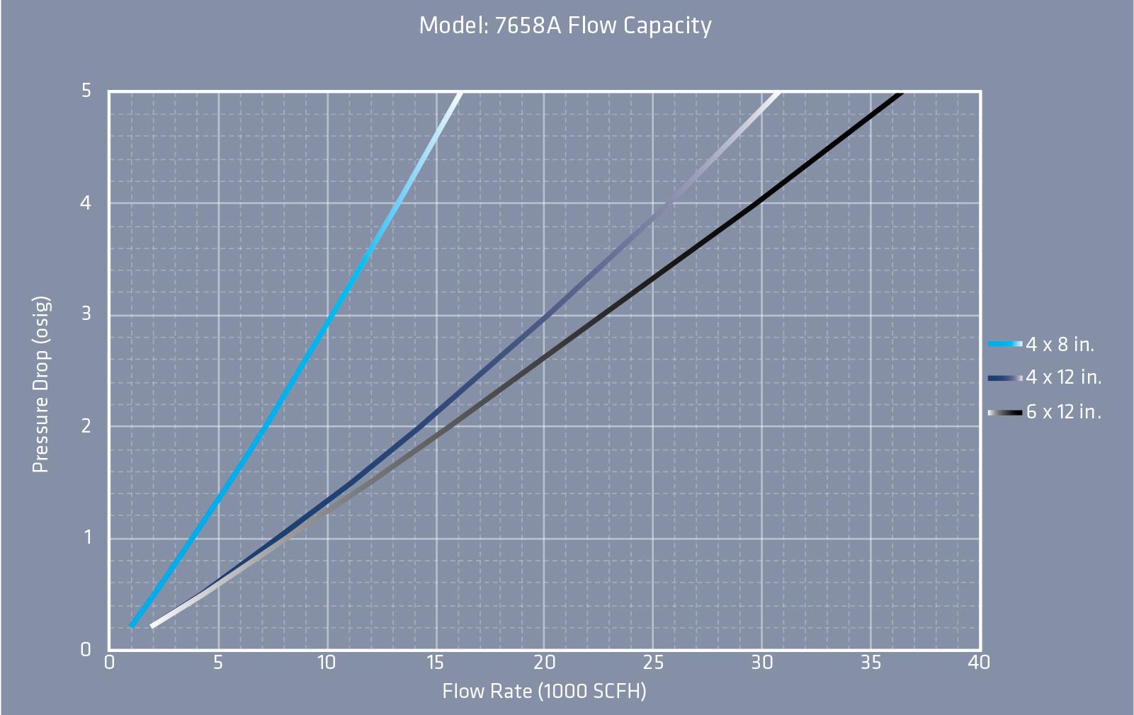
L7658A FLOW CAPACITY
• The test equipment, procedures, and reporting methods meet the requirements of standards API 2000/ISO 28300 and ISO 16852. The equipment, methods, and results have been reviewed and certified by TÜV SÜD
• Flow data are for in-line mounting and does not include entrance losses or exit losses
• Flow values based on air at 60°F venting to atmospheric pressure of 14.6959 psia
L7658A HOW TO ORDER
For easy ordering, select proper model numbers
Notes
• Include model number and setting when ordering
• For special options, consult factory
Example
Housing Material
= Stainless Steel
= Special
O = No Options
S = Swing Bolts
I = Instrument Connections
Z = Special Options
F = 150# R.F. ANSI Flange
D = DIN PN16 Flange
Z = Special Flange Drilling
Indicates a 3” Model L7658A with Carbon Steel housing, 6” Stainless Steel Flame Element, ANSI Flanged Outlet and no other options.
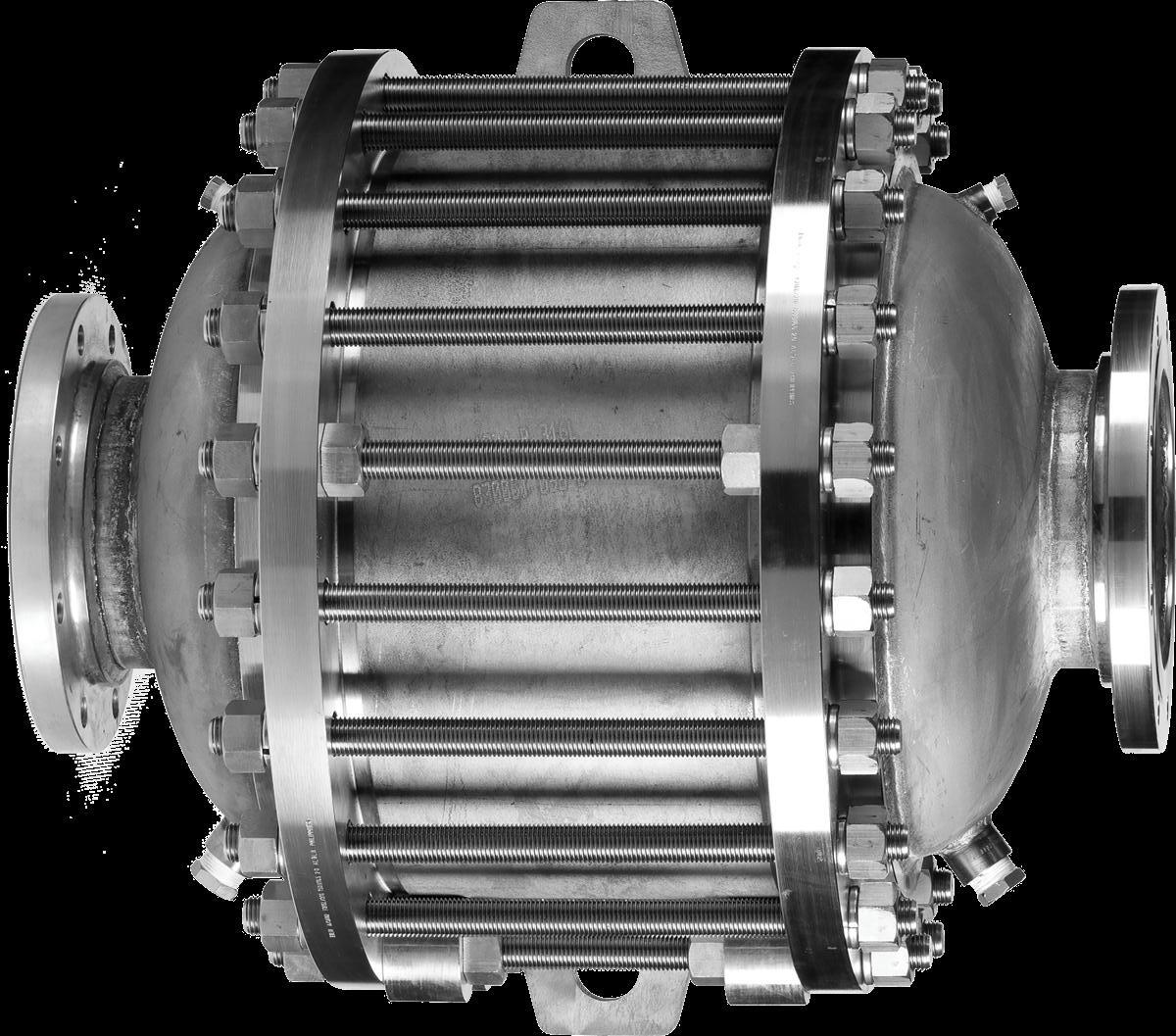
MODEL L7661
The LaMOT Valve & Arrestor Model L7661 inhibits flame propagation in gas piping systems. It is ideal for protecting liquid storage tanks containing NEC Group D (IEC Class IIA) gases with a maximum experimental safe gap equal to or greater than 0.90 mm. Ideal for vertical or horizontal installation, in-line or end-of-line deflagrations and unstable detonations.
Technical Details
• Connection Size: 4” through 12”
• Vertical or horizontal installation
• In-line or end-of-line deflagrations
• Unstable detonations
• Pre-ignition system pressure up to 15.7 psia (1.08 bara)
• Pre-ignition system temperatures -4 to 140°F (-20 to 60°C)
• Burn Time tBT 20 minutes
• Bi-directional with respect to flow and ignition source
• Standard materials of construction are carbon steel or stainless steel
• Stainless Steel element is standard
• Low pressure drop with multiple element sizes available for each flange size
Features
• Compact design with high flow capacity and low pressure drop
• Easy element removal for cleaning and maintenance
• Elements are economical to replace
Options
• Housings are available in carbon steel , stainless steel or Alloy C276 and elements in stainless steel, Alloy C276 or other corrosion resistant alloys
• Sensor ports
• Large inspection and cleaning ports
• Swing bolts for faster element removal
• Factory installed thermocouplers for flame sensing
L7661 SPECIFICATIONS
Specifications subject to change without notice. Certified dimensions available upon request Larger sizes available on special application All units with ANSI 150 RF flanges standard (other flange drillings available).
Model L7661 Operating Zone
The NEC and IEC are the two recognized standards for gas groupings. The NEC is used in the United States while the IEC is international in scope and widely used in Europe. Both the NEC and IEC classify gases into explosion groups based on their maximum experimental safety gap (“MESG”). Customer is responsible for ensuring product selection based on MESG.
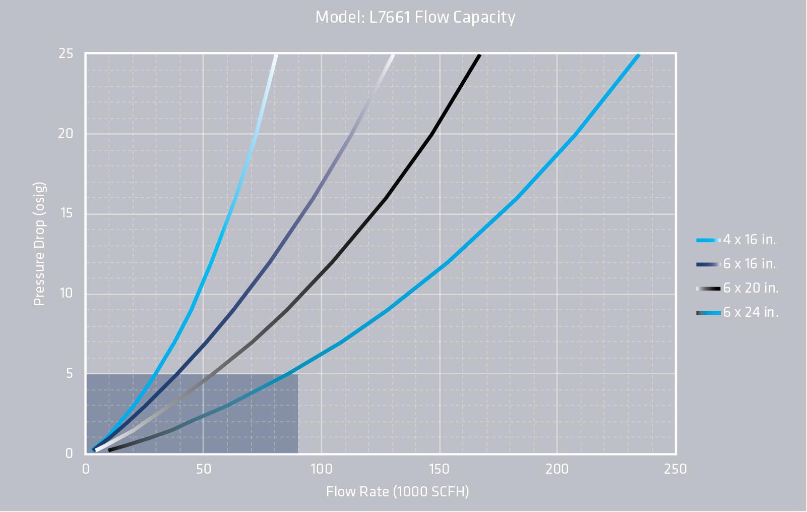
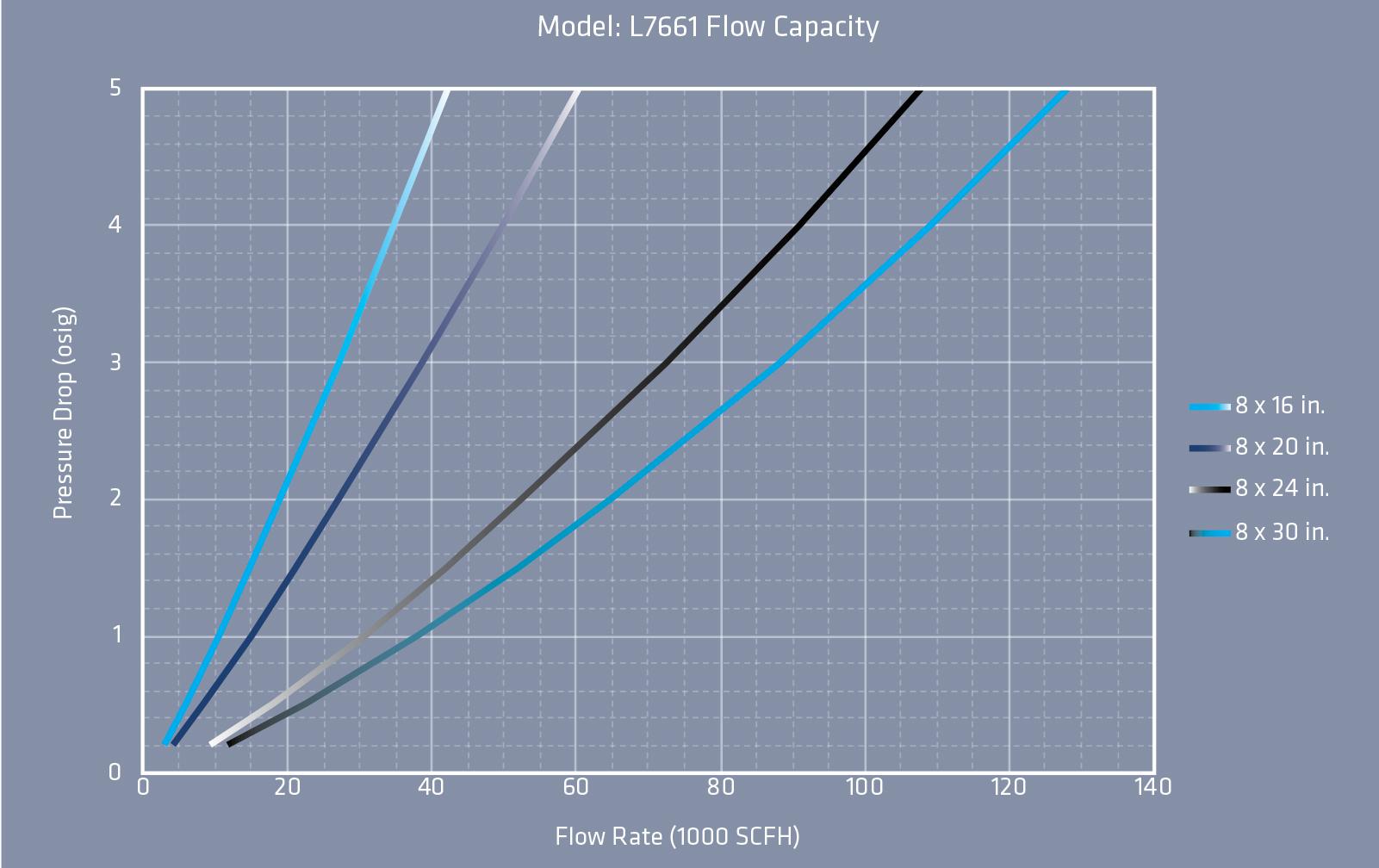
L7661 FLOW CAPACITY
• The test equipment, procedures, and reporting methods meet the requirements of standards API 2000/ISO 28300 and ISO 16852. The equipment, methods, and results have been reviewed and certified by TÜV SÜD.
• Flow data are for in-line mounting and does not include entrance losses or exit losses
• Flow values based on air at 60°F venting to atmospheric pressure of 14.6959 psia
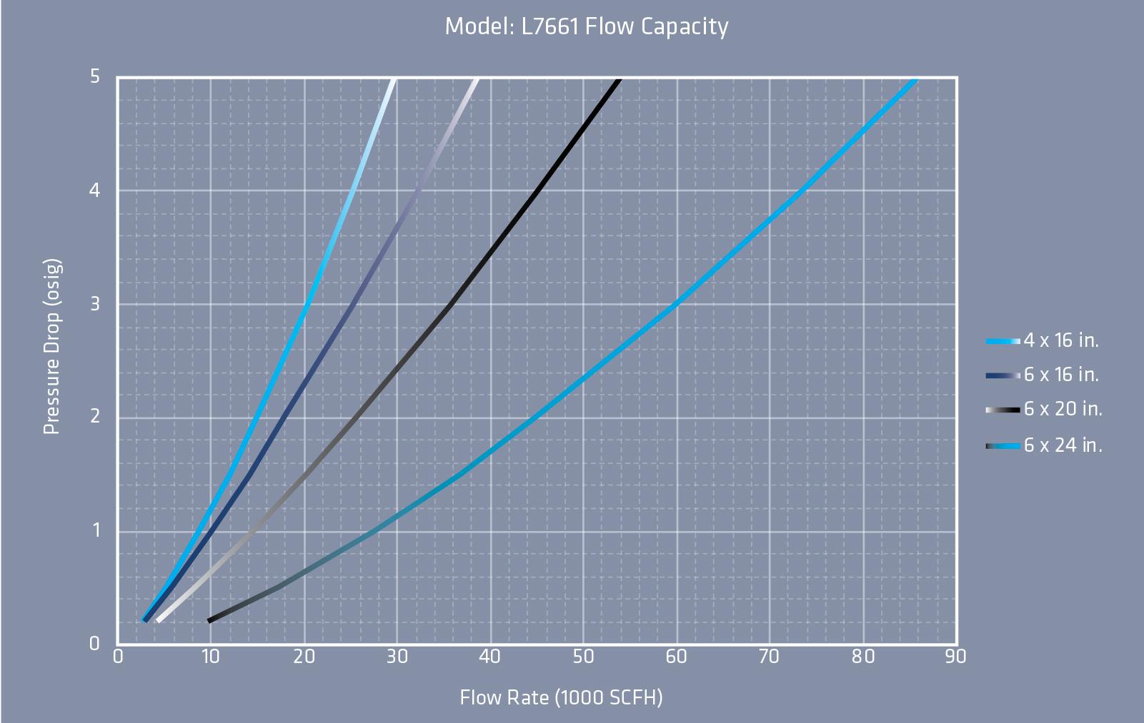
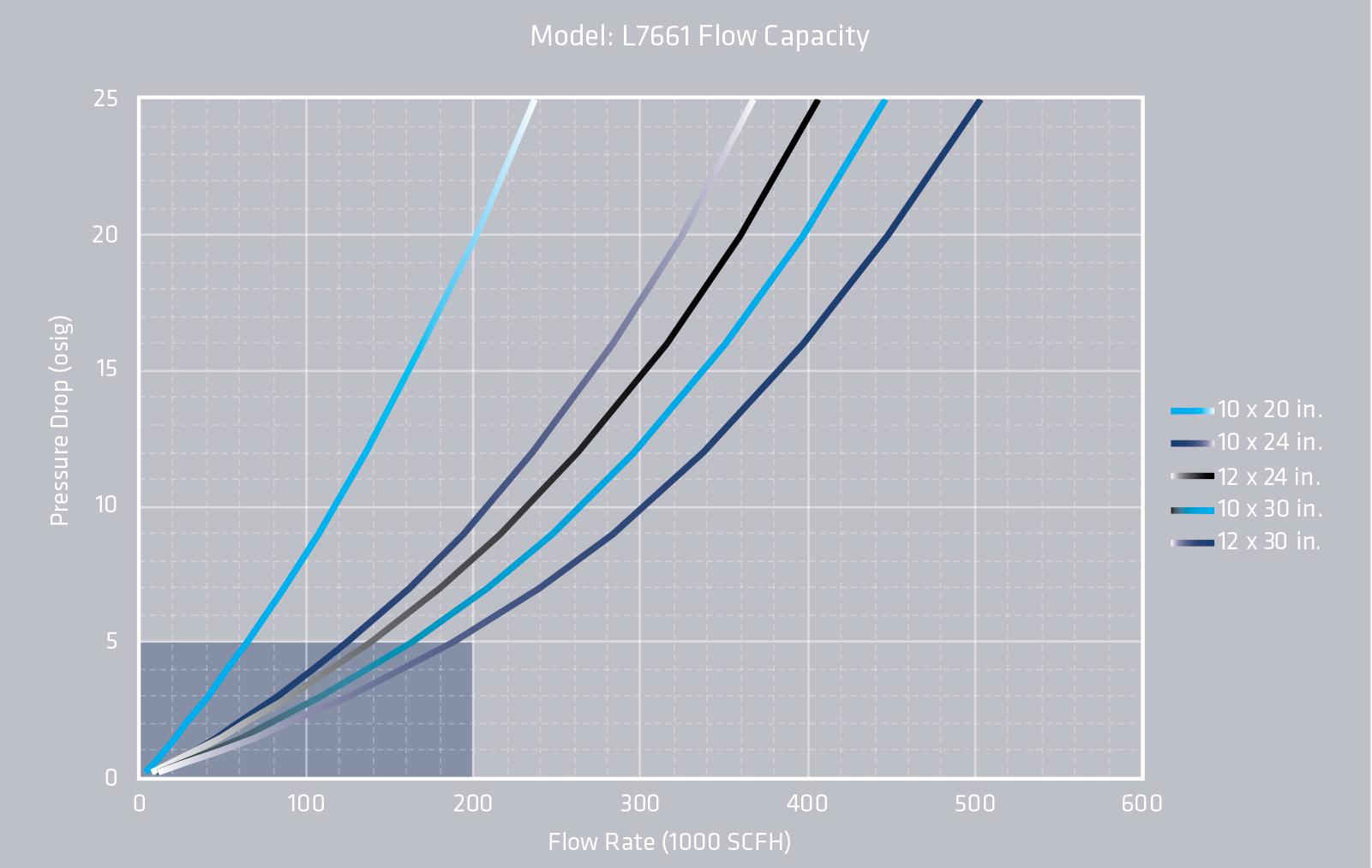
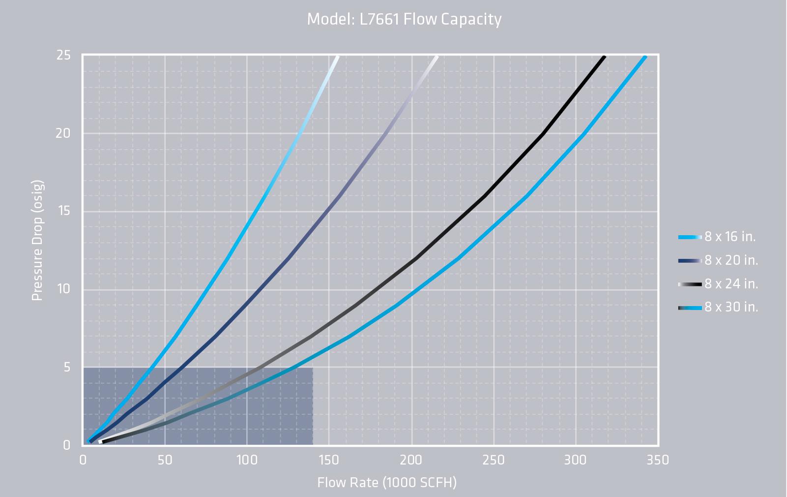
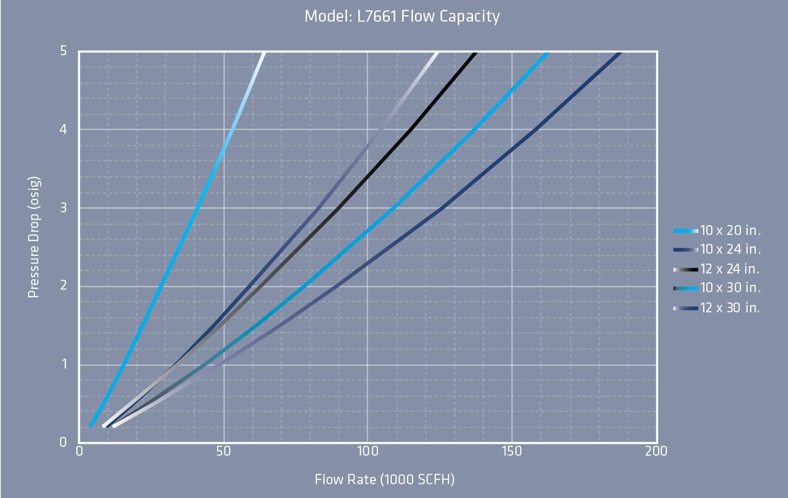
L7661 HOW TO ORDER
For easy ordering, select proper model numbers
L7661
Flange Element
04 thru 12
Notes
• Include model number and setting when ordering
• For special options, consult factory
Example
Flame Element Winding Material
= Stainless Steel
= Special
Housing Material 3 = Carbon Steel 5 = Stainless Steel Z = Special
Z = Special Flange Drilling 16 thru 30 x 0 4
Indicates a 4” Model L7661 with Carbon Steel housing, 16” Stainless Steel Flame Element, ANSI Flanged Outlet and no other options.