VACUUM RELIEF VALVES
MODELS 1300A & 1301A
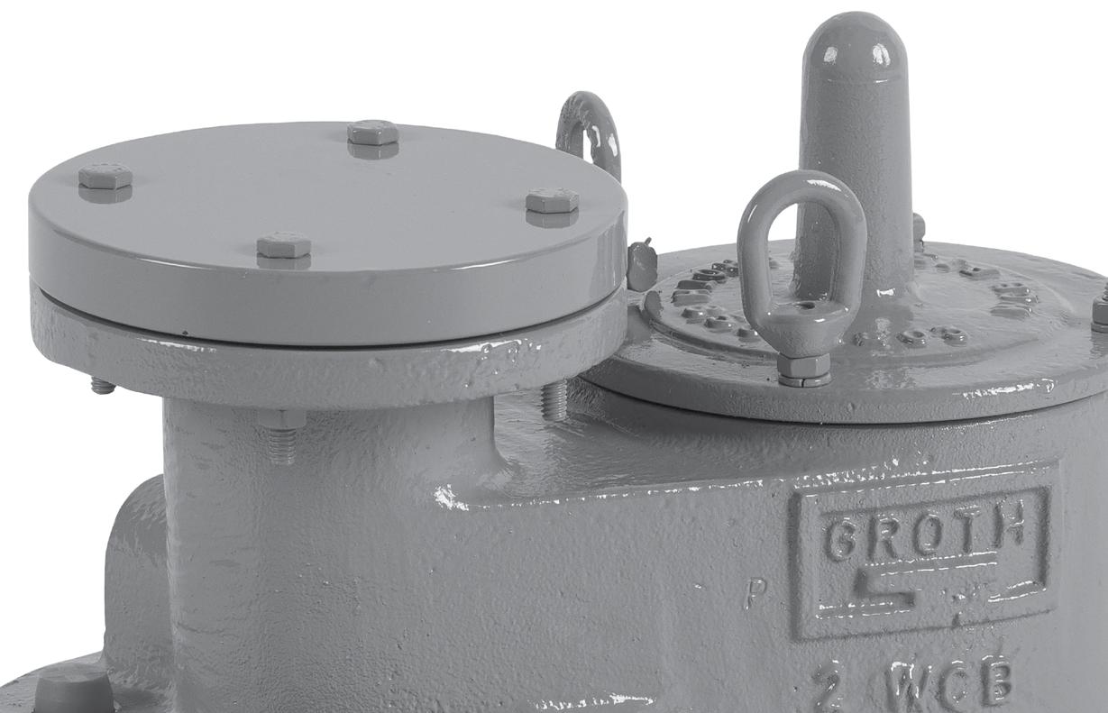


The Groth Models 1300A & 1301A are used when vacuum relief is the only requirement. Intake relief necessary under working conditions is achieved by a spring or weight loaded pallet. This feature reduces the possibility of tank damage due to an excessive vacuum condition. Valve size must be selected to perform required vacuum relief under operating and thermal conditions.
Technical Details
• Certification: ATEX and PED Approval
• Materials: Aluminum, Carbon Steel, Stainless Steel, special materials upon request
Model 1300A
• Sizes: 2” (DN50) through 12” (DN300)
• Vacuum Settings: 0.5 osi to 17.3 osi (2.15 mbarg to 1.19 barg)
Model 1301A
• Sizes: 2” (DN50) through 12” (DN300)
• Vacuum Settings: 1 psig to 12 psig (68.9 mbarg to 827 mbarg)
• Additional Materials: Fiberglass
Features
• Modular Construction
• Cushioned air seating
• Fluoropolymer seating diaphragms minimize sticking caused by resinous vapors and atmospheric moisture
• Self-draining housing body and drip rings to protect seating surfaces from condensate and freezing
• Design avoids vacuum buildup due to binding or clogging of the vent
Options
• Seating Diaphragm Options: FKM, Buna-N or other materials

See TPD for Vacuum Settings and MAWP
† W.P. = Working Pressure. ‡ On spring loaded valves, change model number. ◊ 150# ANSI. drilling compatibility, F.F. on aluminum and R.F. on carbon steel and stainless steel alloys. Fiberglass dimensions on request. 16 oz/in2 set with spacer. SS set weights-consult factory. *Some sizes require non-ferrous components to achieve 0.5 oz./in2 setting.
Flow Capacity Calculation
Flow capacity values listed above are based on full open valves at 100% over-vacuum. Read the flow capacity at 100% over-vacuum directly from the table above. Use linear interpolation if the set vacuum is not listed. If the allowable over-vacuum is less than 100%, modify the flow capacity using the appropriate “C” factor from the table. If allowable over-vacuum is more than 100%, consult your Groth Representative.
Calculate the percentage over-vacuum by the following formula. Note that all pressures are gauge pressure expressed in the same units of measure.
Pf = Flowing pressure
Ps = Set pressure
% OV = [(Pf - Ps)/Ps] x 100
Calculate flow capacity at less than 100% over-vacuum according to the following example.
Example Flow Capacity Calculation
Example to find “C” factor from table:
Read “C” factor for 75% Over-vacuum at intersection of row 70 and column 5
“C” factor at 75% OV = 0.87
6” Model 1300A 1.Read flow capacity at set pressure from table Flow = 74,000 SCFH
4 InWC Set Vacuum [Ps]2.Calculate over-vacuum
Flow Capacity Calculation
Flow capacity values listed above are based on full open valves at 100% over-vacuum. Read the flow capacity at 100% over-vacuum directly from the table above. Use linear interpolation if the set vacuum is not listed. If the allowable over-vacuum is less than 100%, modify the flow capacity using the appropriate “C” factor from the table. If allowable over-vacuum is more than 100%, consult your Groth Representative.
Calculate the percentage over-vacuum by the following formula. Note that all pressures are gauge pressure expressed in the same units of measure.
Pf = Flowing pressure
Ps = Set pressure
% OV = [(Pf - Ps)/Ps] x 100
Calculate flow capacity at less than 100% over-vacuum according to the following example.
Example Flow Capacity Calculation
6” Model 1300A
Example to find “C” factor from table: Read “C” factor for 75% over-vacuum at intersection of row 70 and column 5
“C” factor at 75% OV = 0.87
1.Read flow capacity at set vacuum from table Flow = 2,080 NCMH
100 mmWC Set Vacuum [Ps]2.Calculate over-vacuum
1.0013.830.552.9120197302422
1.1014.531.955.4126206316442 1.2015.133.257.7131215330460
Flow Capacity Calculation
Flow capacity values listed above are based on full open valves at 100% over-vacuum. Read the flow capacity at 100% over-vacuum directly from the table above. Use linear interpolation if the set pressure is not listed. If the allowable over-vacuum is less than 100%, modify the flow capacity using the appropriate “C” factor from the table. If allowable over-vacuum is more than 100%, consult your Groth Representative.
Calculate the percentage over-vacuum by the following formula. Note that all pressures are gauge pressure expressed in the same units of measure.
Pf = Flowing pressure
Ps = Set pressure
% OV = [(Pf - Ps)/Ps] x 100
Calculate flow capacity at less than 100% over-vacuum according to the following example.
Example Flow Capacity Calculation
6” Model 1301A
Example to find “C” factor from table: Read “C” factor for 75% over-vacuum at intersection of row 70 and column 5
“C” factor at 75% OV = 0.83
1.Read flow capacity at set vacuum from table Flow = 166,000 SCFH
2 psig Set Vacuum [Ps]2.Calculate over-vacuum % OV = [(3.50 - 2.0)/2.0] x 100 = 75%
3.5 psig Flowing Vacuum [Pf]3.Read “C” factor from table “C” = 0.83
4.Calculate flow capacity Flow = 0.83 x 166,000 = 137,780 SCFH
0.070.410.901.553.525.778.8712.4
0.100.481.061.834.166.8310.514.6
Flow Capacity Calculation
Flow capacity values listed above are based on full open valves at 100% over-vacuum. Read the flow capacity at 100% over-vacuum directly from the table above. Use linear interpolation if the set pressure is not listed. If the allowable over-vacuum is less than 100%, modify the flow capacity using the appropriate “C” factor from the table. If allowable over-vacuum is more than 100%, consult your Groth Representative.
Calculate the percentage over-vacuum by the following formula. Note that all pressures are gauge pressure expressed in the same units of measure.
Pf = Flowing pressure
Ps = Set pressure
% OV = [(Pf - Ps)/Ps] x 100
Calculate flow capacity at less than 100% over-vacuum according to the following example.
Example Flow Capacity Calculation
6” Model 1301A
Example to find “C” factor from table: Read “C” factor for 72% over-vacuum at intersection of row 40 and column 2
“C” factor at 42% OV = 0.55
1.Read flow capacity at set vacuum from table Flow = 4,530 NCMH
0.12 barg Set Vacuum [Ps]2.Calculate over-vacuum % OV = [(0.17 - 0.12)/0.12] x 100 = 42%
0.17 barg Flowing Vacuum [Pf]3.Read “C” factor from table “C” = 0.55
4.Calculate flow capacity Flow = 0.55 x 4,530 = 2,492 NCMH

2680 New Butler Rd. New Castle, PA 16101
Tel: 724-368-8725
Email: sales@portersvillerd.com
700 Southlake Blvd. North Chesterfield VA 23236
Tel: 804-593-2384
Email: sales@portersvillerd.com
www.portersvilleprd.com
143 S.Thomas Rd. Tallmadge, OH 44278
Tel: 330-253-4800
Email: sales@portersvilleprd.com
1551 Shipley Ferry Road Blountville, TN 37617
Tel: 423.482.0496
Email: sales@portersvillerd.com

1500 E. Burnett St. Signal Hill, CA 90755
Tel: 562-424-8108
Email: Sales@BV-BM.com
www.bv-bm.com
403 Technology Dr South Point, OH 45680
Tel: 740-377-0012
Email: sales@portersvilleprd.com

3800 Fruitvale Avenue Bakersfield, CA 93308
Tel: 661-589-6801
Email: Sales@BV-BM.com
3195 Park Road, Benicia, CA 94510
Tel: 707-590-6688
Email: Sales@BV-BM.com
For easy ordering, select proper model numbers
1300A Weight Loaded
1301A Spring Loaded
Pallet Material
Seat Material
Body Material
= Stainless Steel
= Vinyl Ester Resin
= Furan
= Special
Notes
• Include model number and setting when ordering.
• For special options, consult factory.
• When ordering steam jacket, include steam pressure / temperature.
* Stainless steel guides, stems are standard with aluminum and carbon steel bodies. Stainless steel seats standard with carbon steel bodies.
Indicates a 2” Model 1300A with Aluminum Body and Seat, Stainless Steel Pallet, Fluoropolymer Seat Diaphragm, and no other options.
O = No Options
Z = Special Options
O = No Jacket
J = Steam Jacket
S = Spacer
H = Steam Jacket & Spacer
Diaphragm Material (Seat):
B = Buna-N
T = Fluoropolymer
V = FKM
Z = Special