PILOT RELIEF VALVE
1400 SERIES

1400 SERIES
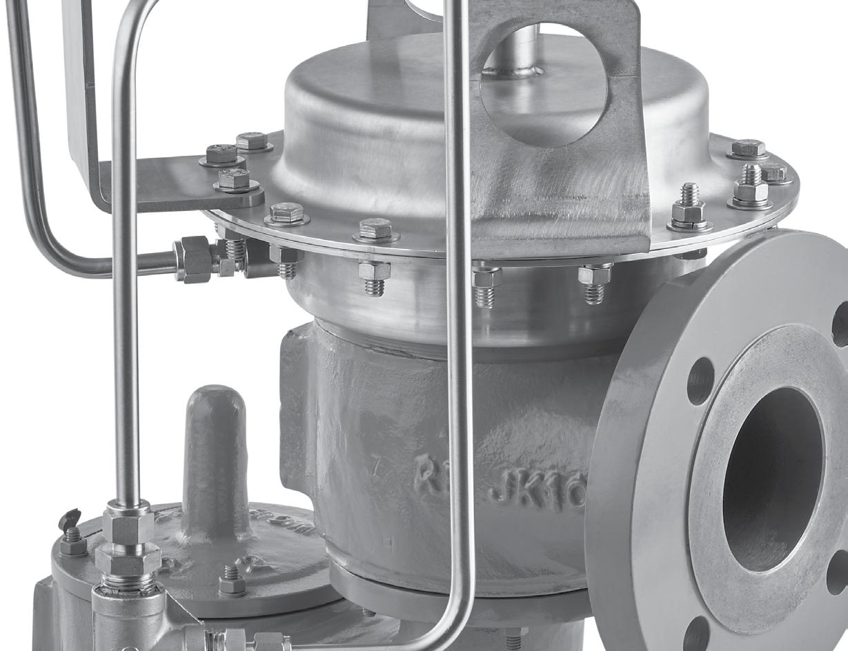
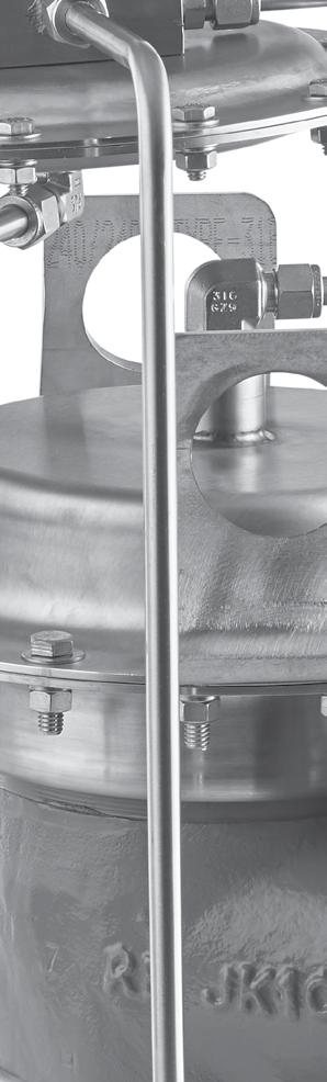
The Groth 1400 Series Pilot-Operated Relief Valves are used to replace weight-loaded or spring loaded valves in many applications to increase efficiency and reduce evaporation losses. Several advantages are obtained over the traditional valves. For example, the process pressures may be closer to the set pressure than would be considered prudent and safe with the traditional valve. Additionally, greater conservation is obtained due to minimum product loss which in turn provides increased profits.
Technical Details
• Size: 2” (DN 50) through 12” (DN 300)
• Material: Standard body materials are carbon steel, stainless steel, aluminum and fiberglass
• Pressure: from 2.0* InWC to 15 psig * Requires 1402 Pilot for minimum settings
• Vacuum: from 7.0 InWC to 1 psig
• Certification: ATEX and PED Approval
Features
• Ease of precision settings
• Only the pilot needs to be set
• Lower profile and weight than spring operated models for high settings
• Remote pilot sensing option allows the pilot to sense the true system pressure
• Remote or manual blowdown available
• Main valve remains tight to set pressure
• Full open at 10% overpressure
• Modulating action conserves product
• Soft seating creates tight seal to conserve product and minimize valve wear
• Top entry allows valve to be services without removal from mounting
Options
• 150# ANSI, PN10, PN16, JIS drilling classes
• Pilot exhaust piped to discharge header
• Field test connection
• Manual blow down
• Remote sense pickup
• Pilot supply filter


PAGE 2
Model 1400
Model 1420
Model 1430
Model 1460
Models 1400 and 1430
*Approximate
PAGE 3
Models 1420 and 1460 Size In (mm) Standard Settings A In (mm) B In (mm) D In (mm) E In (mm) G In (mm) AA In (mm) BB In (mm) DD In (mm) Approx. Ship Wt. Lbs (kg)* Pressure VACUUM InletOutletMax**MinMaxMin 2 (50) 3 (80) 10.50 (267) 23.50 (587) 4.12 (105) 5.50 (140) 7 (178) 14.50 (368) 26.50 (673) 7 (178) 35 (16) 3 (80) 4 (100) 11.50 (292) 25.50 (648) 5 (127) 6 (152) 7.50 (191) 18 (457) 28.75 (730) 8.12 (206) 40 (18) 4 (100) 6 (150) 12.50 (318) 28.50 (724) 6.50 (165) 6.50 (165) 8 (203) 19.25 (489) 31.50 (800) 9.50 (241) 50 (23) 6 (150) 8 (200) 16.75 (425) 32.25 (819) 8.50 (216) 8.50 (216) 10.25 (260) 26.50 (673) 36.50 (927) 12.75 (324) 70 (32) 8 (200) 10 (250) 20.50 (521) 36.75 (933) 9.75 (248) 10.75 (273) 11.75 (298) 32.50 (826) 42.25 (1073) 15.25 (387) 90 (41) 10 (250) 12 (300) 20.25 (514) 38.75 (984) 10.25 (260) 12.50 (318) 13.75 (349) 37.75 (959) 46.50 (1181) 18 (457) 125 (57) 12 (300) 14 (350) 27.75 (705) 42.75 (1086) 11 (279) 15 (381) 14.75 (375) 42.75 (1086) 52.50 (1334) 20.62 (524) 150 (69) 15 psig (1.035 barg) 7 InWC (17.5 mb) 12 psig (.828 barg) 0.5 oz/in2 (2.16 mb)
weight of aluminum Model 1420. **2 InWC minimum set with 1402 Pilot. Model 1420 Model 1460
SPECIFICATIONS
*Approximate
Size In (mm) STANDARD SETTINGS A In (mm) B In (mm) G In (mm) AA In (mm) BB In (mm) Approx. Ship Wt. Lbs (kg)* PRESSURE VACUUM MAX.**MIN.MAX.MIN. 2 (50) 4.75 (121) 25.50 (648) 7 (178) 13.50 (343) 27.50 (699) 30 (14) 3 (80) 5.75 (146) 26.50 (673) 7.75 (197) 17.75 (451) 29 (737) 35 (16) 4 (100) 6.50 (165) 27.50 (699) 8.50 (216) 19.50 (495) 30.25 (768) 40 (18) 6 (150) 8.50 (216) 29.50 (749) 10.50 (267) 26.50 (673) 34 (864) 50 (23) 8 (200) 9.75 (248) 32.50 (826) 11.75 (298) 31.50 (800) 40 (1016) 6 (30) 10 (250) 11.75 (298) 34.50 (876) 13.75 (349) 37 (940) 43.75 (1111) 95 (43) 12 (300) 12.75 (324) 36.50 (927) 14.75 (375) 40.50 (1029) 48 (1219) 125 (57) 15 psig (1.035 barg) 7 InWC (.17.5 mb) 12 psig (.828 barg) 0.5 oz/in2 (2.16 mb)
weight of
1400. **2 InWC
Model 1430 Model 1400 AA BB G A B G AA E BB DD G AA B D G
aluminum Model
minimum set with 1402 Pilot
OPERATION
The pilot operated valve is a self-contained system which does not require any external power or pressure source. The pilot valve, using system medium and pressure, automatically controls the actuator pressure to either open or close the main valve depending on the pressure setting of the pilot vs. the actual system pressures.
System medium and pressure is sensed at the pickup fitting just above the inlet flange. In the case of remote sensing, the pickup point is directly on the vessel and usually close to the valve inlet. The medium and pressure is then channeled to the pilot inlet and is redistributed to the sense chamber and to the actuator.
Under normal system operating conditions, the same pressure is acting downward against the actuator and upwards against the seat pallet. Since the actuator has a larger area than the seat pallet, the net force is downward which will press the pallet against the seat and thus keep the main valve closed. While the pilot and main valve are closed, there is no bleed to the atmosphere.
When the system pressure rises to the pilot set point due to an overpressure condition, the upward force in the pilot sense chamber will overcome the downward spring force to lift the pilot stem. As the stem lifts, it opens the pilot seat to allow flow through the pilot and out to the atmosphere (in applications where nothing is permitted to discharge directly into the atmosphere, the pilot discharge may be plumbed to the main valve outlet for channeling to a collection header. Notify the vendor if this is the situation in case compensating adjustments need to be made). The flow through the pilot and adjustable orifice will cause a pressure drop downstream of the orifice which in turn causes the pressure in the actuator to drop. When the actuator pressure decreases to a point where the upward force on the seat pallet is greater than the downward force of the actuator, the main valve will open. The amount the main valve opens depends on the system overpressure. The greater the overpressure, the wider the main valve opens, until full open is obtained at approximately 10% overpressure.
After the excess pressure has been relieved and the system pressure is again below the set point of the pilot, the valve will return to its normal closed position.
PAGE 4
Sense Chamber Pilot Exhaust Outlet Inlet Pilot Pickup Main Valve Seat Pallet Actuator Diaphragm Adjustable Orifice
PAGE 5
Field Test Connection (Backflow Prevention Included) Pilot Discharge Tubed to Main Valve Outlet Manual or Remote Blowdown Remote Pickup for Pilot Pilot
Test Connection To Body Pick-Up or Remote Sense
Body Pick-Up or Remote Sense Pilot Pilot Pilot
Blowdown
Body Pick-Up or Remote Sense
Remote Sense
CONFIGURATIONS
Field
To
Provisions for Remote
To
To
PAGE 6 Vacuum Setting InWC Valve Size 2" 3" 4" 6" 8" 10" 12" 0.87 46801032016020346806048091080 129000 1.00 50401098017220373206498097920 138000 1.73 666014520226204902085320129000 181980 2.00 714015600241805262091620138000 195000 3.00 8700190202958064200112020169020 238020 4.0010020219003408073980129000193980 274020 6.00 12180267004152090120157020237000 334020 8.00139803060047700103020180000271980 384000 10.00156003402052980115020199980301980 427020 SIZING TABLES It is suggested that API Standard 2000 be utilized to obtain the required flow capacity. SCFH Air Capacity @ 10% Overpressure and 60°F . For an equivalent size fiberglass valve, reduce tabulated capacities by 32%. Pressure Setting psig Valve Size (Orifice Size) 2" (2.976 in2) 3" (7.013 in2) 4" (12.35 in2) 6" (28.51 in2) 8" (49.65 in2) 10" (78.47 in2) 12" (112.7 in2) 0.07 508212000211804884085080134460193080 0.2 8460199803522081300141600223800321360 0.4 124202928051600119100207420327840470820 0.6 155403660064500148860259260409800588540 0.8 181804290075540174420303720480000689400 1.0 205804848085380197160343320542400779340 1.2 227405358094380217920379440599700861300 1.4 2478058320102720237120412920652620937260 1.6 26640627601105202551204442407021201008420 1.8 28380669001178402721004738207488601075500 2.0 30060709201248602881805019007932601139280 3.0 37500884401557003595206260409894601421100 4.0 4386010338018204042024073182011566201661100 5.0 4950011658020532047400082554013047001873860 6.0 5406012744022446051816090234014261402048220 7.0 5826013734024180055824097218015364802206680 8.0 62160146400257880595260103668016384202353080 9.0 65760154920272820629820109680017334602489640 10.0 69120162900286860662220115332018227402617860 11.0 72300170460300120692880120666019071002739000 12.0 75360177600312720721980125730019871402853960 13.078240184440324780749700130560020634002963520 14.081000190920336240776220135174021363603068280 15.083700197160347220801600139596022063203168720 Models 1400 and 1430 Pressure Setting psig Valve Size (Orifice Size) 2" (2.976 in2) 3" (7.013 in2) 4" (12.35 in2) 6" (28.51 in2) 8" (49.65 in2) 10" (78.47 in2) 12" (112.7 in2) 0.07 461410860192004422076080118800168540 0.2 7680181203192073620126660197760280500 0.4 110402604045840105840182100284280403200 0.6 136803222056760130980225360351840499080 0.8 159003750066060152520262380409560580920 1.0 179404224074340171660295320460980653880 1.2 197404650081960189120325920507960720480 1.4 214205052088980205380353340551580782340 1.6 230405424095580220620379500592500840360 1.8 2454057840101820235020404340631200895320 2.0 2598061200107760248760427980668160947700 3.0 32400763201344003102605337608332201181820 4.0 37980894601575603637206257409768601385520 5.0 4302010140017856041214070908011069401570080 6.0 4770011244019800045708078636012276001741260 7.0 5214012282021630049938085914013412401902420 8.0 5634013272023376053964092844014493602055780 9.0 6036014226025050057828099486015531002202900 10.064260151380266640615540105894016531202344800 11.068040160320282300651600112104017500802482320 12.0 71700168960297480681780117210018283802591340 13.0 75240177360310620707940121704018985202690820 14.078480184920321600732960126006019656602785980 15.0 81060190980332100756960130134020300402877180 Models 1400 and 1430
PAGE 7 Pressure Setting mbar Valve Size (Orifice Size) 2" 3" 4" 6" 8" 10" 12" 5 134 318 560 1290 2220 3468 4920 10 190 449 792 1824 3138 4902 6960 20 274 648 1134 2622 4518 7020 10020 30 339 798 1410 3246 5586 8700 12360 40 394 930 1638 3780 648010140 14400 50 445 1050 1842 4254 732011460 16200 100 630 1488 2622 60601044016260 23040 150 780 1836 3228 74401284020040 28380 200 906 2124 3750 86401488023220 32940 250 1014 2388 4206 97201674026100 37020 300 1116 2628 4626106801836028680 40680 350 1230 2892 5088117602022031560 44760 400 1332 3138 5526127802196034260 48600 450 1434 3372 5940137402358036840 52260 500 1530 3600 6360146402520039300 55740 550 1620 3816 6720155402670041700 59160 600 1710 4032 7080163802820044040 62460 650 1800 4242 7440172202964046260 65640 700 1884 44407800180603108048480 68820 750 1968 4644 8160188403246050700 71880 800 2052 4836 8520195003354052380 74220 850 2136 50288820201003450053820 76320 900 2208 5202 9060205803546055260 78360 1000 2322 54669480216603726058140 82380 Vacuum Setting InWC Valve Size 2" 3" 4" 6" 8" 10" 12" 2 132 288 449 972 1698 2556 3612 3 161 353 549 1194 2076 3126 4422 4 186 406 630 1374 2394 3606 5094 5 208 454 708 1536 2676 4026 5694 7 245 536 834 1812 3156 4752 6720 10 292 636 996 2160 3762 5664 7980 15 356 780 1212 2628 4584 6900 9780 20 409 894 1392 3018 5262 7920 11220 25 455 996 1548 3354 5850 882012480 Pressure Setting mbar Valve Size (Orifice Size) 2" 3" 4" 6" 8" 10" 12" 5 148 350 618 1428 2484 3924 5634 10 210 496 876 2016 3510 5550 7980 20 308 726 1278 2952 5142 810011700 30 385 906 1602 3690 64201014014580 40 451 1062 1872 4326 75601188017100 50 511 1200 2118 489085201344019320 100 726 1716 3024 6960121201920027600 150 900 2118 3726 8580150002370034020 200 1044 2460 433210020174002754039540 250 1170 2766 487211220195603096044460 300 1290 3048 536412360215403408048960 350 1422 3348 589813620237003750053820 400 1536 3624 636014760256804056058260 450 1644 3876 684015780274804338062340 500 1728 4080720016560288604566065580 550 1812 4272 750017340302404776068580 600 1890 4446 786018060315004974071460 650 1962 4620 816018780327005166074220 700 2028 4782 840019440338405346076800 750 2094 4938 870020040349205520079320 800 2160 5088894020700360005688081720 850 2220 5232 918021240370205850084060 900 2280 5370 948021840379806006086280 1000 2394 5646 996022980399606318090720 SIZING TABLES It is suggested that API Standard 2000 be utilized to obtain the required flow capacity. NCMH AIR CAPACITY @10% OVERPRESSURE AND 0° C For an equivalent size fiberglass valve, reduce tabulated capacities by 32%.
1430 Models 1400 and 1430
Models 1400 and

NEW CASTLE
2680 New Butler Rd. New Castle, PA 16101
Tel: 724-368-8725
Email: sales@portersvillerd.com
RICHMOND
700 Southlake Blvd. North Chesterfield VA 23236
Tel: 804-593-2384
Email: sales@portersvillerd.com
www.portersvilleprd.com
TALLMADGE
143 S.Thomas Rd. Tallmadge, OH 44278
Tel: 330-253-4800
SOUTH POINT
403 Technology Dr South Point, OH 45680
Tel: 740-377-0012
Email: sales@portersvilleprd.com

SIGNAL HILL
1500 E. Burnett St. Signal Hill, CA 90755
Tel: 562-424-8108
Email: Sales@BV-BM.com
www.bv-bm.com

BAKERSFIELD
3800 Fruitvale Avenue Bakersfield, 93308
Tel: 661-589-6801
Email: Sales@BV-BM.com

© 2024 PRD Technologies Group LLC - All Rights Reserved. 01/2024
P AG E 8 CONTACT YOUR LOCAL SALES REPRESENTATIVE
HOW TO ORDER
For easy ordering, select proper model numbers
MODEL #
SIZEMATERIAL OPTIONS
1400
1420
1430
1460
02 = 2"
= 3"
Main Valve Trim
1 = Aluminum
5 = 316 S.S.
Z = Special
Body Material
1 = Aluminum
3 = C. Steel
5 = 316SS
Z = Special
B = Buna-N
E = EPR
K = FFKM (see note 5)
T = Fluoropolymer (see note 6)
V = FKM
Z = Special
Notes
1. See 1660 Brochure for details on 1401E or 1402 Pilot Valves.
2.Carbon and Stainless Steel Valves include 316 SS Trim.
3.Diaphragm material for main actuator and pilot valve are only available in Fluoropolymer FEP.
4.300 Series Pilot is standard; see 1660 Brochure for pilot valve details.
5.FFKM O-Rings; Fluoropolymer FEP Diaphragms and Gaskets.
6.Fluoropolymer FEP Diaphragms and Gaskets with FKM O-rings.
7. 1402 Pilot Valve available for modulating service only.
8.Pilot Exhaust Piped to Discharge Header is not available w/1402 Pilot Valve. Pilot will only exhaust vapors in the dome.
O = No Options
Z = Special Options
O = No Blowdown or Remote Sense
B = Manual Blowdown
R = Remote Sense
2 = Both Blowdown and Remote Sense
O = No Pilot to Header or Test Connection
H = Pilot Exhaust Piped to Discharge Header (see note 8)
T = Field Test Connection
2 = Both Pilot to Header & Test Connection
O = No Filter or Low Set 1402Pilot
F = Pilot Supply Filter
L = Low Set 1402 Pilot
2 = Both Filter and Low Set 1402 Pilot (see note 7 & 8)
Indicates a 6” Model 1430 with carbon steel body and 316SS trim using FKM soft goods, snap action with remote pilot pickup and no other options.
Groth Corporation reserves the right to alter the information in this publication without notice. // © 2020 Groth Corporation Reproduction without written permission is prohibited. LIT19151 // 0420 GROTHCORP.COM
Example 3 0 0 6 V R O O 4 O oooo oo oo o o oooo 1
03
04
4" 06
6" 08
8" 10
10" 12
12"
M = Modulating S = SnapAction GOODS TYPE 3 5 S
=
=
=
=
=
SOFT
