PRESSURE/VACUUM VALVE & FLAME ARRESTER
MODEL 8820A
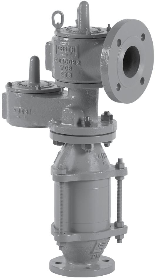


The Groth Model 8820A Pressure/Vacuum Relief Valve & Flame Arrester are designed to protect your tank from damage created by overpressure or excessive vacuum, at the same time they provide protection from flame propagation. The result is reduced emission level and increased fire protection and safety.
Technical Details
• Sizes: 2” (DN 50) through 12” (DN 300)
• Pressure Settings 0.5oz/in2 to 15 psig
• Vacuum Settings: 0.5 oz/in2 to 12 psig
• Materials: Aluminum, Carbon Steel, Stainless Steel and other materials
Features
• Cushioned Air Seating
• Fluoropolymer seating diaphragms are standard to minimize sticking caused by resinous vapors and atmospheric moisture
• Self draining housing and drip rings
• Spiral-wound, crimped ribbon flame element
• Modular Construction
Options
• Buna-N, Fluoropolymer, FKM

† W.P. = Working Pressure. ‡On spring loaded valves, change model number. ◊150# R.F. drilling compatibility F.F. on aluminum and R.F. on carbon steel and stainless steel alloys. 16 oz/in2 set with spacer. SS set weights-consult factory. *Some sizes require non-ferrous components to achieve 0.5 oz/in2 setting
Flow capacity values listed above are based on full open valves at 100% overpressure. Read the flow capacity at 100% overpressure directly from the table above. Use linear sted. If the allowable overpressure is less than 100%, modify the flow capacity using the appropriate “C” factor from the table. If allowable overpressure is more than 100%, consult your Groth Representative.
Calculate the percentage overpressure by the following formula. Note that all pressures are gauge pressure expressed in the same units of measure.
Pf = Flowing pressure
Ps = Set pressure
% OP = [(Pf - Ps)/Ps] x 100
Calculate flow capacity at less than 100% overpressure according to the following example.
Example Flow Capacity Calculation
6” Model
4 InWC
pressure
7 InWC flowing pressure [Pf]3.Read “C” factor from table
Example to find “C” factor from table: Read “C” factor for 75% overpressure at intersection of row 70 and column 5
“C” factor at 75% OP = 0.87
Flow Capacity Calculation
Flow capacity values listed above are based on full open valves at 100% overpressure. Read the flow capacity at 100% overpressure directly from the table above. Use linear interpolation if the set pressure is not listed. If the allowable overpressure is less than 100%, modify the flow capacity using the appropriate “C” factor from the table. If allowable overpressure is more than 100%, consult your Groth Representative.
Calculate the percentage overpressure by the following formula. Note that all pressures are gauge pressure expressed in the same units of measure.
Pf = Flowing pressure
Ps = Set pressure
% OP = [(Pf - Ps)/Ps] x 100
Calculate flow capacity at less than 100% overpressure according to the following example.
Example Flow Capacity Calculation
Example to find “C” factor from table: Read “C” factor for 67% overpressure at intersection of row 60 and column 7
“C” factor at 75% OP = 0.82
6” Model 8820A 1.Read flow capacity at set pressure from table Flow = 2,080 NCMH
150 mmWC Set Pressure [Ps]2.Calculate overpressure % OP = [(250 - 150)/150] x 100 = 67%
250 mmWC Flowing Pressure [Pf] 3.Read “C” factor from table “C” = 0.82
4.Calculate flow capacity Flow = 0.82 x 2,080 = 1,706 NCMH
Flow Capacity Calculation
Flow capacity values listed above are based on full open valves at 100% over-vacuum. Read the flow capacity at 100% over-vacuum directly from the table above. Use linear interpolation if the set vacuum is not listed. If the allowable over-vacuum is less than 100%, modify the flow capacity using the appropriate “C” factor from the table. If allowable over-vacuum is more than 100%, consult your Groth Representative.
Calculate the percentage over-vacuum by the following formula. Note that all pressures are gauge pressure expressed in the same units of measure.
Pf = Flowing pressure
P s = Set pressure
% OV = [(Pf - Ps)/Ps] x 100
Calculate flow capacity at less than 100% over-vacuum according to the following example.
Example Flow Capacity Calculation
Example to find “C” factor from table: Read “C” factor for 75% Over-vacuum at intersection of row 70 and column 5
“C” factor at 75% OV = 0.87
6” Model 8820A 1.Read flow capacity at set vacuum from table Flow = 46,700 SCFH
4 InWC Set Vacuum [Ps]2.Calculate over-vacuum %
Flow Capacity Calculation
Flow capacity values listed above are based on full open valves at 100% over-vacuum. Read the flow capacity at 100% over-vacuum directly from the table above. Use linear interpolation if the set vacuum is not listed. If the allowable over-vacuum is less than 100%, modify the flow capacity using the appropriate “C” factor from the table. If allowable over-vacuum is more than 100%, consult your Groth Representative.
Calculate the percentage over-vacuum by the following formula. Note that all pressures are gauge pressure expressed in the same units of measure.
Pf = Flowing pressure
P s = Set pressure
% OV = [(Pf - Ps)/Ps] x 100
Calculate flow capacity at less than 100% over-vacuum according to the following example.
Example Flow Capacity Calculation
Example to find “C” factor from table: Read “C” factor for 67% over-vacuum at intersection of row 60 and column 7
“C” factor at 67% OV = 0.82
6” Model 8820A 1.Read flow capacity at set vacuum from table Flow = 1,660 NCMH
150 mmWC Set Vacuum [Ps]2.Calculate over-vacuum %

2680 New Butler Rd. New Castle, PA 16101
Tel: 724-368-8725
Email: sales@portersvillerd.com
700 Southlake Blvd. North Chesterfield VA 23236
Tel: 804-593-2384
Email: sales@portersvillerd.com
www.portersvilleprd.com
143 S.Thomas Rd. Tallmadge, OH 44278
Tel: 330-253-4800
Email: sales@portersvilleprd.com
1551 Shipley Ferry Road Blountville, TN 37617
Tel: 423.482.0496
Email: sales@portersvillerd.com

1500 E. Burnett St. Signal Hill, CA 90755
Tel: 562-424-8108
Email: Sales@BV-BM.com
www.bv-bm.com
403 Technology Dr South Point, OH 45680
Tel: 740-377-0012
Email: sales@portersvilleprd.com

3800 Fruitvale Avenue Bakersfield, CA 93308
Tel: 661-589-6801
Email: Sales@BV-BM.com
3195 Park Road, Benicia, CA 94510
Tel: 707-590-6688
Email: Sales@BV-BM.com
For easy ordering, select proper model numbers
MODEL #
Flame Element Pallet Seat Body*
1 = Aluminum
3 = Carbon Steel
5 = 316 SS
Z = Special
Notes
• Include model number and setting when ordering.
• For special options, consult factory.
• When ordering steam jacket, include steam pressure/temperature.
O = No Options
Z = Special Options
Diaphragm Material (Seat):
B = Buna-N
T = Fluoropolymer
V = FKM
Z = Special
* Stainless steel guides, stems are standard with aluminum and carbon steel bodies. Stainless steel seats standard with carbon steel bodies.
Example
8820A 8 8 2 0 0 2 1 1 A 02 = 2” thru 12 = 12" T O 5 1
Indicates a 2” Model 8820A with Aluminum Body and Seat, 316 SS Pallet, Fluoropolymer Seat Diaphragm, and no other options.