FLAME ARRESTER
MODEL 7658A
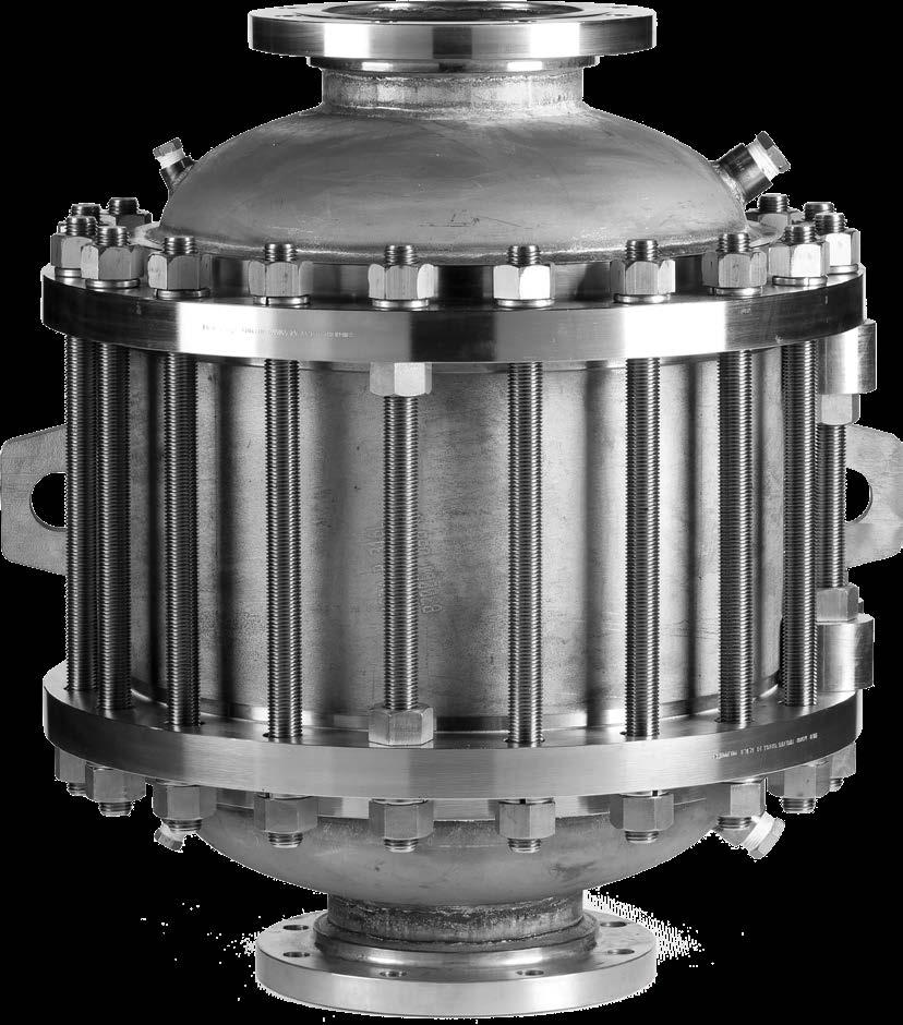


The Groth Model 7658A Deflagration & Detonation Flame Arrester inhibits flame propgation in gas piping systems. The design makes it ideal to protect liquid storage tanks containing NEC Group D (IEC Class IIA) gases.
Technical Details
• Sizes: 2” (DN50) x 5” (DN125) through 8” (DN200) x 16” (DN400)
• Housings Materials: Carbon Steel, Stainless Steel, Alloy C276
• Element Materials: Stainless Steel, Alloy C276 or other corrosion resistant alloys
• Consult the factory for specific information by size for Stable/Unstable detonations and deflagrations
• Vertical or horizontal installation
• Pre-ignition system pressure up to 15.7 psia (1.08 bara)
• Pre-ignition system temperatures -4 to 140°F (-20 to 60°C)
• Burn time tBT 10 minutes
• Many sizes certified to ATEX and/or US Coast Guard, please consult factory for information
Features
• Compact with high flow capacity and low pressure drop
• Elements are easily removed in-line for cleaning and maintenance
Options
• Sensor ports
• Large inspection and cleaning ports
• Swing bolts for fast element removal
• Factory installed thermocouples for flame sensing

* Larger sizes available on special applications. All units with ANSI 150 RF flanges standard (other flange drillings available).


• The test equipment, procedures, and reporting methods utilized by Groth Corporation meet the requirements of standards API 2000/ISO 28300 and ISO 16852. The equipment, methods, and results have been reviewed and certified by TÜV SÜD.
• Flow data are for in-line mounting and does not include entrance losses or exit losses.
• Flow values based on air at 60°F venting to atmospheric pressure of 14.6959 psia
4


• The test equipment, procedures, and reporting methods utilized by Groth Corporation meet the requirements of standards API 2000/ISO 28300 and ISO 16852. The equipment, methods, and results have been reviewed and certified by TÜV SÜD.
• Flow data are for in-line mounting and does not include entrance losses or exit losses.
• Flow values based on air at 60°F venting to atmospheric pressure of 14.6959 psia


• The test equipment, procedures, and reporting methods utilized by Groth Corporation meet the requirements of standards API 2000/ISO 28300 and ISO 16852. The equipment, methods, and results have been reviewed and certified by TÜV SÜD.
• Flow data are for in-line mounting and does not include entrance losses or exit losses.
• Flow values based on air at 0°C venting to atmospheric pressure of 1.01325 bara
For easy ordering, select proper model numbers
Notes
Flame Element Winding
Material
O = No Options
= Swing Bolts
= Instrument Connections*
= Special Options
= 150# R.F. ANSI Flange
= DIN PN16 Flange
= Special Flange Drilling X Flange 02 = 2” thru 06 = 6" Element 05 = 5" thru 12 = 12"
• Include model number when ordering.
• For special options, consult factory.
• See flow table for available sizes.
*Customer specified size
Indicates a 3” Model 7658A with Carbon Steel housing, 6” Stainless Steel Flame Element, ANSI Flanged Outlet and no other options.

2680 New Butler Rd. New Castle, PA 16101
Tel: 724-368-8725
Email: sales@portersvillerd.com
700 Southlake Blvd. North Chesterfield VA 23236
Tel: 804-593-2384
Email: sales@portersvillerd.com
www.portersvilleprd.com
143 S.Thomas Rd. Tallmadge, OH 44278
Tel: 330-253-4800
Email: sales@portersvilleprd.com
1551 Shipley Ferry Road Blountville, TN 37617
Tel: 423.482.0496
Email: sales@portersvillerd.com

1500 E. Burnett St. Signal Hill, CA 90755
Tel: 562-424-8108
Email: Sales@BV-BM.com
www.bv-bm.com
403 Technology Dr South Point, OH 45680
Tel: 740-377-0012
Email: sales@portersvilleprd.com

3800 Fruitvale Avenue Bakersfield, CA 93308
Tel: 661-589-6801
Email: Sales@BV-BM.com
3195 Park Road, Benicia, CA 94510
Tel: 707-590-6688
Email: Sales@BV-BM.com