

V Series Valve Solutions
The Flagship of the ValvTechnologies’ Product Line

Applications
ValvTechnologies’ valves are built to withstand the most severe applications. High-pressure, high-temperature, high-cycle, abrasive, corrosive and caustic media have all been considered in the design of our product line.


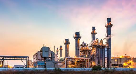
Fossil Fuel
Above and below seat drains
Ash handling
At temperator spray control
Boiler drains
Boiler feed pump isolation
Continuous boiler blowdown
Electronic relief
Feedwater heater drains
Feedwater isolation
Instrument isolation
Main steam stop
Recirculation
Seal steam regulators
Sight/gauge glass drains
Soot blower regulators
Startup vents
Steam dump
Turbine bypass systems
Turbine drain
Nuclear Generation
Boiler feedwater
Circulating water system
Component cooling
Condensate extraction
Condensate cooling water
Emergency feedwater
Fire protection system
HP safety injection
HP and LP heater drains
Heat exchanger vent and drains
Main steam system isolation, drain and vent
Power operated relief valve (PORV)
Pressurizer drain and vent
Rad waste system
Reactor coolant pump drain and vent
Reactor head vents
Reactor water cooling vents and drains
Safety injection system
Secondary system isolation, drain and vent
Service water system isolation
Steam generator system
Turbine bypass
Turbine drain and vent
Fukushima tie-ins
Reliable hardened vents
Upstream Oil and Gas
Wellhead choke isolation
HIPPS
Emergency shutdown
Compressor recycle and isolation
Sour gas isolation and control
Steam, water and gas injection
Steam chokes
SAG-D isolation
Pig launcher and receiver
Mud drilling isolation and check
Lean and rich amine isolation
Molecular sieve regeneration isolation
Molecular sieve absorber isolation
First and second stage separator isolation


Downstream and Chemical Processing
Coking (delayed and flexi)
Switching
Feed isolation
Overhead vapor line
Cutting water isolation
Fluidized catalytic cracking
Catalyst handling
Slurry isolation and control steam
Ethylene
Steam decoke isolation
Furnace isolation
Steam vent
Quench oil isolation and control
Polyethylene
Isolation
Hig h-cycle (PTO)
Reactor block
Heavy oil upgrading and hydrocracking (H-oil and LC fining)
Catalyst addition and withdrawal
Filter and pump isolation
Overhead vapor isolation and control
Hig h ∆P isolation and control
Reforming (CCR)
Lock hopper
Isolation
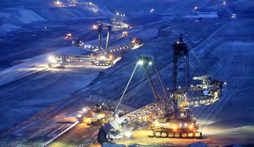
Mining and Minerals Processing
High-pressure slurry
Transportation systems
Pump discharge isolation
Pipeline isolation stations
Pipeline choke stations
Rupture disc isolation
Instrument isolation
Autoclaves
Vessel feed and discharge
Acid injection
Gas injection
Steam injection
Mineral concentrators
Thickener underflow
Discharge isolation
Filter press manifold isolation
Slurry transfer systems
PR V isolation
Waste disposal
Tailings pipelines
Paste backfill

Pulp and Paper
Boiler vent and drain
Liquor isolation and control
Rapid drain
Steam isolation
Sk y vents
Dr yer pressure control
Digester steam control
Lime mud isolation and control
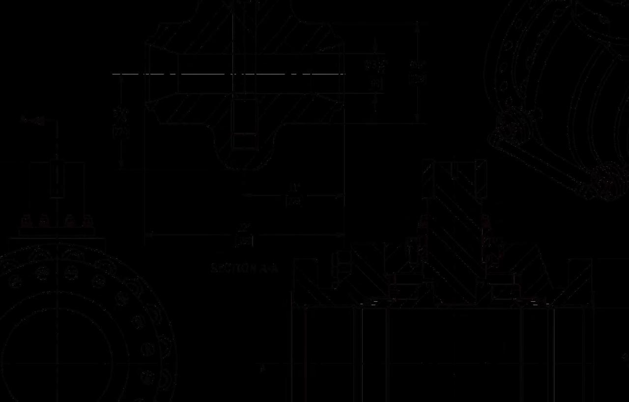
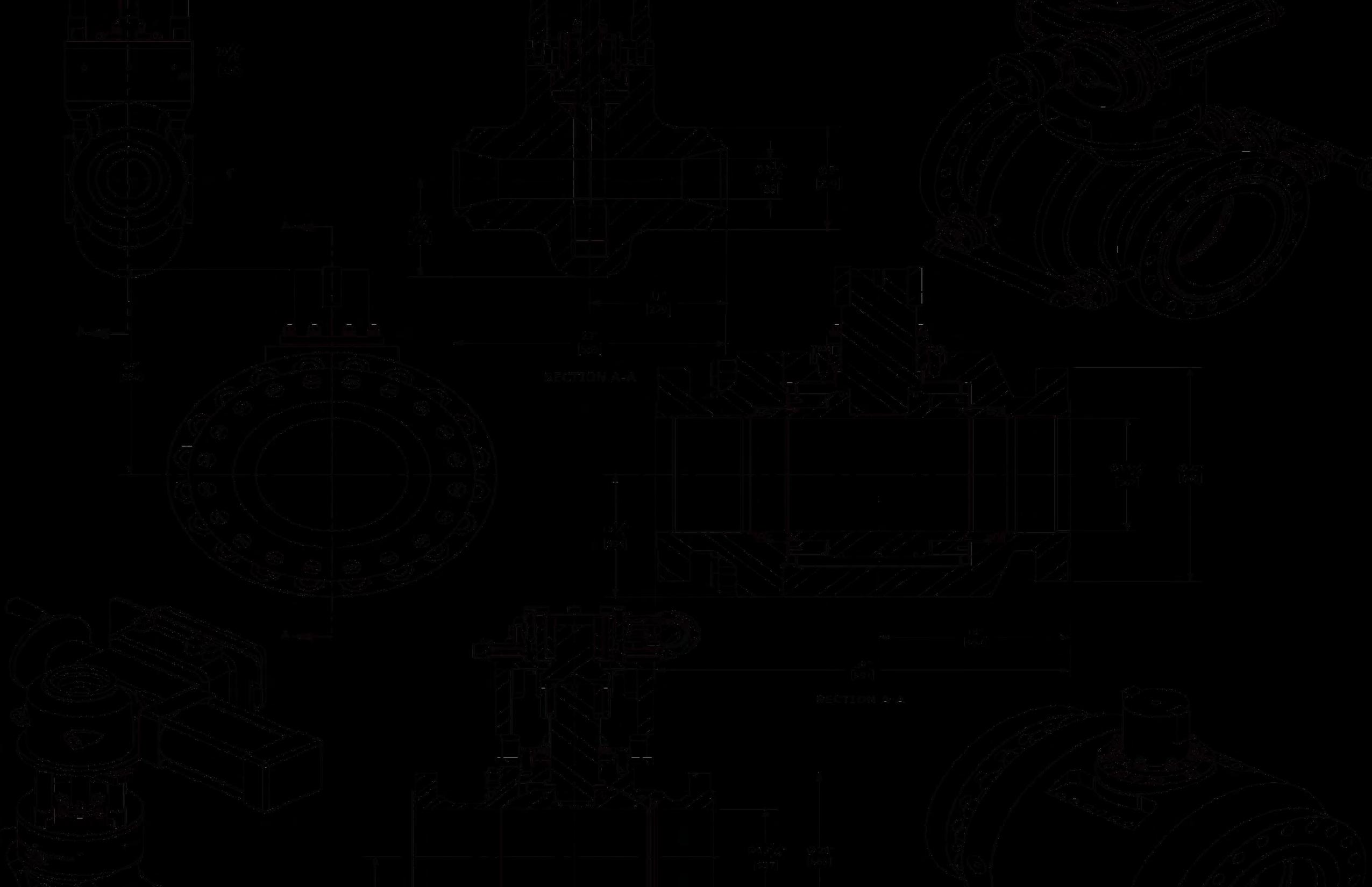
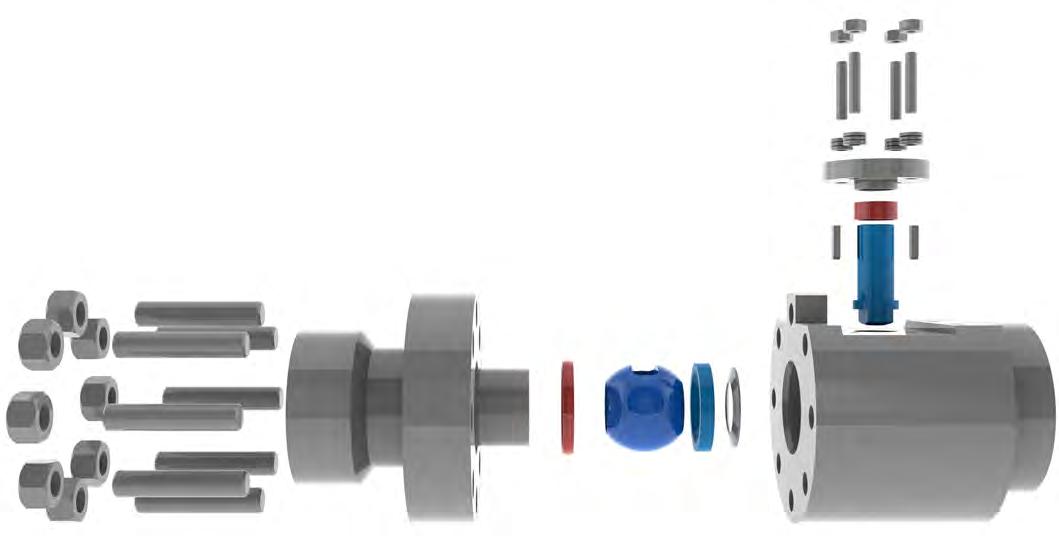
V Series Metal Seated Ball Valves
The flagship of the ValvTechnologies’ product line
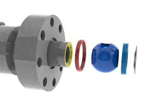
1.Integral metal seat
With our patented HVOF RiTech® coating technology, the integral seat in ValvTechnologies’ valves is resistant to the attack of abrasive and corrosive production applications.
2.Body seal ring
ValvTechnologies employs a field-proven seal ring technology to ensure sealing under all operating conditions, up to 1400°F. The body seal ring is loaded at a pressure higher than 20,000 psi. In addition, valves sized 3” and above contain a secondary Grafoil® seal to further guarantee reliability
3.Patented coating process
The sealing surfaces are overlaid with tungsten or chromium carbide using our HVOF RiTech® coating process. These surfaces have a hardness of 68 - 72 Rc to provide uninterrupted operation in the most severe conditions with zero-leakage.
4.Live-loaded gland area
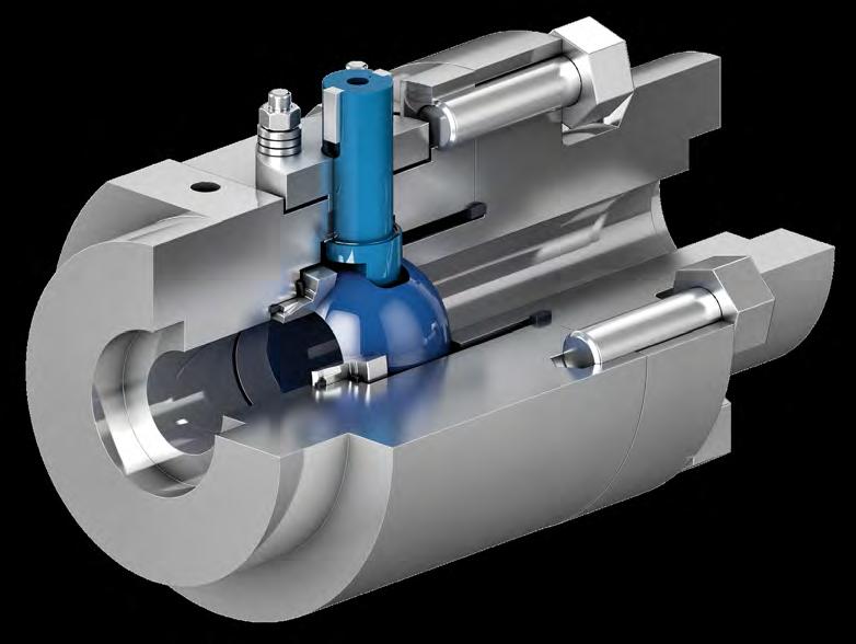
The V Series’ sealing design features a four stud, live- loaded assembly designed for heavy industrial applications. The sealing material is high purity Grafoil® surrounded by stainless steel wire mesh anti-extrusion rings. The six Belleville® springs (per stud) provide constant load pressure through extreme thermal shocks and prevent wear leaks in high-cycle service.
5.Blow-out proof stem
ValvTechnologies’ design utilizes a one-piece, hard-coated, blow-out proof stem that is inserted through the inside of the body cavity eliminating the possibility of blow-out through the gland area. There are no pins, collars or other devices used to retain the stem in the valve body.
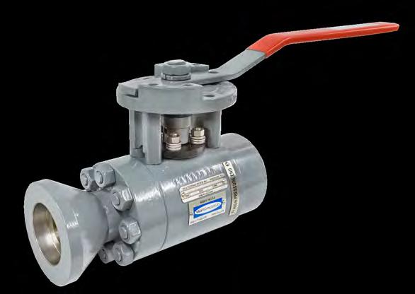
V1-1
Forged, high-pressure valves Four-year, zero-leakage warranty*
1/4 - 4“
ANSI/ASME Class 900 - 4500

V1-2
Flanged, low-pressure valves
1/2 - 36“
ANSI/ASME Class 150 - 600

V1-3
Small bore, low and intermediate pressure investment cast valves Four-year, zero-leakage warranty*
1/2 - 2“
ANSI/ASME 150 - 600
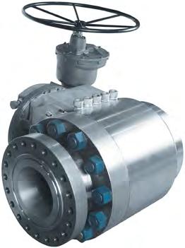
V1-4
Large bore, high-pressure valves
4 - 36“
ANSI/ASME Class 900 - 4500
Features
V Series Key Performance Features and Benefits
Benefits
Guaranteed tight shut-off
Quarter turn operation - readily automated
Low pressure drop - high Cv
Custom engineered
Dimensions to ANSI B16.10
Low emission packing and seals
Single piece anti-blow-out stem design
Resistant to solids
Certified to use in SIL 3 loop
Live-loaded gland system (four stud design)
Stem fugitive emissions per ISO 15848-1 Class B
Fire safe certification: API-607
Enhanced process safety
Increased safety, ease of operation, reduced space requirements
Process efficiency
Process optimization
Interchangeable with equivalent valves
Reduced emissions
Enhanced process safety
Reduced maintenance costs, minimum downtime
Enhanced process safety
Reduced emissions
Reduced emissions, enhanced process safety
Enhanced process safety
The Real Cost of Valve Leakage
The cost of leaking steam and process fluids is far greater than the total cost of a valve.
The cost of replacing or repairing a valve is small compared to the cost of lost heat-rate efficiency in power plants caused by leaking valves. Minor leaks will grow to major leakage, causing frequent equipment repair or replacement and costly unscheduled plant shutdowns. Valves can have severe leakage that is not visible to the eye as internal valve leakage can go undetected for long periods of time.
With zero-leakage severe service isolation valves, less fuel is burned to produce megawatts, which lowers emissions and overall costs of plant operations. ValvTechnologies’ decades of engineering experience have designed a superior severe service isolation valve that exceeds industry standards when it comes to defining zero-leakage.
Zero-leakage is defined as no detectable leakage of gas or a liquid for a period of three minutes or greater.
Allowable leakage rates:
MSS SP-61, 4”, ASME/ANSI Class 1500, reduced port:
Allowable leakage per hour = 0.010565 gallons
Allowable leakage per year = 92.5 gallons
Leakage over four years assuming constant leak path:
gallons
FCI-2 Class V, 4”, ASME/ANSI Class 1500, reduced port:
Allowable leakage per hour = 0.069465 gallons
Allowable leakage per year = 608.5 gallons
Leakage over four years assuming constant leak path:
Guaranteed
Would you specify a valve that will have a significant leak after one year in service? If not, then what specifications do you use? All ValvTechnologies’ valves are guaranteed absolute zero-leakage for fouryears in steam and power applications.
All other valves in the industry have a defined leakage rate. ValvTechnologies tests every valve according to ANSI procedures. However, we toughen the standard to zero-leakage on both water and gas. Our standard is zero drops and zero bubbles guaranteed.
Qualified
At ValvTechnologies, we are totally committed to quality. We measure our performance against the standards set in our Integrated Quality Program. Our Quality Assurance department diligently pursues opportunities for improvement, while the entire organization takes ownership of the quality program. In this way, we can improve our processes while increasing manufacturing efficiency.
Efficient
Cycle isolation eliminates energy losses attributable to poorly performing or leaking steam, water cycle isolation valves. ValvTechnologies encourages end users to apply the principles of asset management to their installed valve population. The ValvPerformance Testing™ program, or cycle isolation measurement, utilizes next generation acoustic monitoring instruments to help customers monitor valve performance. These tools allow predictive and preventative maintenance programs to be fine tuned for very large or very small valve populations. Providing cycle isolation services can be as simple as performing a valve survey, or as comprehensive as the management of all valve work during your next outage - from erecting scaffolds to repairing, installing, welding and stress relieving.
Benefits
Plant efficiency improvement
Economic payback in just months
Improved decision making
Reductions in overall valve maintenance spend
Cost avoidance of unnecessary valve repairs or replacements
Zero-leakage Valve Solutions

Find your local Distributor:
NEW CASTLE
2680 New Butler Rd. New Castle, PA 16101
Tel: 724-368-8725
Email: sales@portersvilleprd.com
RICHMOND
700 Southlake Blvd. North Chesterfield VA 23236
Tel: 804-593-2384
Email: sales@portersvilleprd.com
www.portersvilleprd.com
Headquarters & Manufacturing
ValvTechnologies, Inc.
5904 Bingle Road
Houston, Texas 77092 U.S.A.
Telephone +1 713 860 0400 Fax +1 713 860 0499 info@valv.com.
To locate a distributor or satellite office near you, visit us online at: www.valv.com.
To contact sales anywhere in the world, email sales@valv.com
TALLMADGE
143 S.Thomas Rd. Tallmadge, OH 44278
Tel: 330-253-4800
Email: sales@portersvilleprd.com
KINGSPORT
1551 Shipley Ferry Road Blountville, TN 37617
Tel: 423-482-0496
Email: sales@portersvilleprd.com
SOUTH POINT
403 Technology Dr South Point, OH 45680
Tel: 740-377-0018
Email: sales@portersvilleprd.com
RALEIGH
3915 Beryl Road, Raleigh NC 27607
Tel: 984-238-1720

Email: sales@portersvilleprd.com