
UNISERT® HOLDER ASSEMBLY
MICRO X® Rupture Disc
MICRO X® Rupture Disc

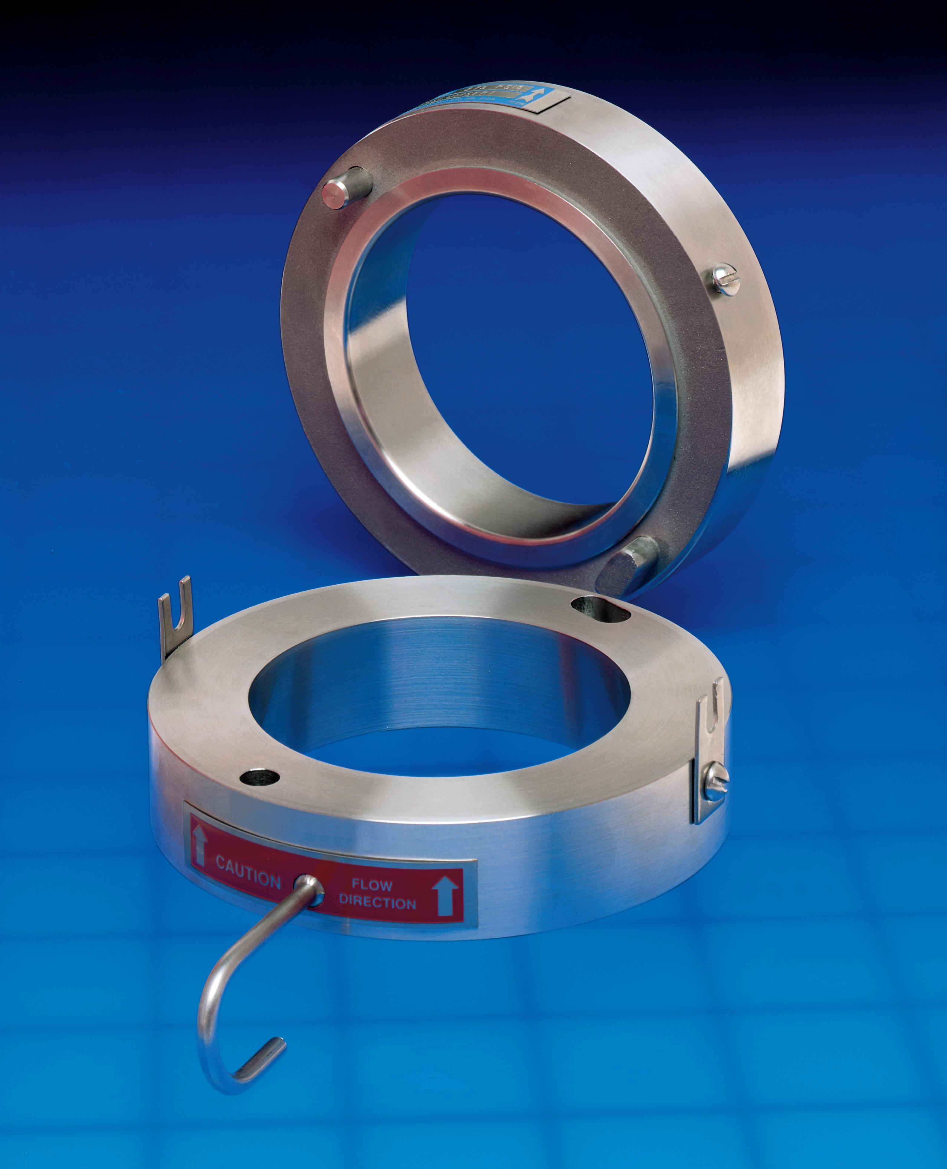
The UNISERT Assembly is a flat seat rupture disc holder which provides improved rupture disc sealing capabilities. It is designed to house either the MICRO X® Rupture Disc or the Composite Flat Seat Rupture Disc. These non-fragmenting designed rupture discs provide a wide choice of burst ratings from the low pressures of the Composite (FS) Rupture Disc through the higher pressures of the scored positive acting MICRO X Rupture Disc.


The UNISERT Assembly is available in nominal sizes ranging from 1" through 36" for installation between ANSI, DIN, or JIS class companion flanges. Standard materials for the UNISERT Holder include 316 Stainless Steel, Carbon Steel, Monel®, and Hastelloy C® (Reference Table V, pages 7 - 10).
One feature the UNISERT Assembly offers is alignment pins for correct rupture disc orientation into the UNISERT Holder. The UNISERT Holder is also equipped with a J-Hook for proper indexing and
flow orientation between the companion flanges. Both the J-Hook and alignment pins are provided on all 1" through 12" UNISERT Holders.


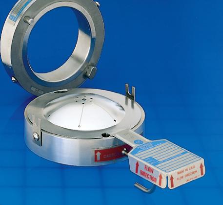
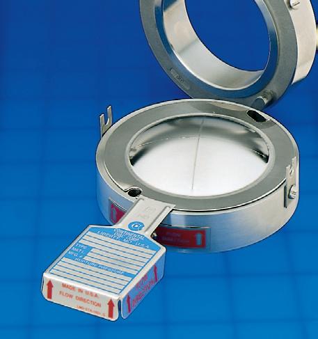
The UNISERT Holder is supplied with a permanently attached stainless steel nameplate with arrows that indicate flow direction. In addition, the Composite (FS) and MICRO X rupture discs are supplied with a three-dimensional flow direction tag. Directional arrows on both the tag and nameplate provide a means to visually verify the rupture disc assembly is properly oriented in your system (see above photo).
In accordance with customer specifications, pertinent identification information will be stamped on the rupture disc and holder tags (see above photo).
In the event that there is a change in system operating requirements, the flexibility of the UNISERT Assembly permits utilization of various rupture disc types in order to meet a wide range of burst pressures. The Composite (FS) Rupture Disc may be selected for handling very low burst pressures, and the MICRO X Rupture Disc can be utilized for higher pressures. Thus, the type of rupture disc can be changed rather than replacing the existing holder.

The MICRO X Rupture Disc is a flat seat cross-scored, tension-type rupture disc. The MICRO X Rupture Disc is designed to provide a full, nonfragmenting, four petal opening pattern. Because the MICRO X Rupture Disc is scored on the outlet (vent) side of the rupture disc, a smooth disc surface is provided on the inlet (process) side of the rupture disc. The result is an undisturbed inlet surface resistant to corrosion and the accumulation of process media.
The Composite Rupture Disc for a Unisert Holder has a flat seat configuration and consists of two or more metallic or non-metallic components. The components typically consist of a metallic top section and metallic or non-metallic seal, with an optional vacuum support, protective rings, gaskets or outlet liner.
Continental Disc Corporation’s Composite (FS) Rupture Disc top section is manufactured with a seven-hole pattern, and with six pre-cut sections providing a non-fragmenting design when used with a non-metallic or Teflon® seal. With the seven-hole pattern, heavier materials of construction can be used. This results in a higher operating to burst pressure ratio – up to 80%.
Continental Disc Corporation manufactures several types of prebulged flat seat rupture discs.

Type CDC is the basic Composite Rupture Disc, consisting of a slotted metal top section and a Teflon or metal seal located on the process side of the top section.
Type CDCV is the same as a CDC Type Rupture Disc, with a vacuum support installed on the process side of the top section and seal.

Type PL is basically the same as the CDC Type Rupture Disc, with the addition of a corrosion resistant Teflon liner on the outlet side of the top section.
Type PLV is the same as the PL Type Rupture Disc, but capable of withstanding full vacuum. The PLV is constructed in the same manner as the PL except a vacuum support is located on the outlet side of the top section. The outlet liner is positioned on top of the vacuum support, protecting the metal top section and the vacuum support from corrosive media.
The MICRO X and Composite Flat Seat rupture discs incorporate a number of outstanding features:
• Excellent for use in gaseous or liquid service
• 80% operating to burst pressure ratio
• Excellent corrosion resistance
• Non-fragmenting design*
• Full, instantaneous opening
• Excellent for use under relief valves
• Permanently attached 3-dimensional flow direction tag is standard
* The non-fragmenting design applies to all MICRO X Rupture Discs, but only to Composite (FS) Rupture Discs supplied with a non-metallic seal.
Generally, the burst pressure of a rupture disc will decrease as operating temperatures increase. Table I states the maximum temperatures for commonly used rupture disc materials, liners, and seals.
Liners—Continental Disc Corporation offers protective liners to provide additional protection from the effect corrosives might have on the performance of the rupture disc. Typically, liners are made of Teflon.
Protective Rings—Protective rings may be used with rupture discs made of thin materials or in instances where delicate liners or seals are used. These rings protect the rupture disc from foreign material in the sealing area where holders may be pitted or corroded from extended use.
Vacuum Support—Thin materials of construction generally require use of a vacuum support to preclude damage to the rupture disc and ensure proper operation when a system vacuum occurs. CDC vacuum supports are manufactured to withstand a full system vacuum and will be supplied when the application requires a vacuum support. Each vacuum support is mated with a specific rupture disc and is attached to that rupture disc. When ordering a MICRO X Rupture Disc (sizes 6" and above) or Composite (FS) Rupture Disc that will be subjected to a vacuum condition, clearly specify the exact conditions that the rupture disc will encounter. For backpressure conditions higher than 14.7 psig (1 barg), consult your Continental Disc representative or the factory.
Sizes/Materials—The MICRO X and Composite (FS) rupture discs manufactured for use with the Unisert Holder are available in nominal sizes ranging from 1" (25mm) through 36" (900mm). Standard materials of construction are 316 Stainless Steel, Monel, Nickel and Inconel®. Consult Table II & III for minimum and maximum burst pressures for MICRO X and Composite (FS) rupture discs.
Gaskets—Gaskets may be used to provide additional sealing and prevent leakage through the seating area of a scratched or pitted holder. They are located on the process side of the rupture disc and are usually manufactured from Teflon. Other materials are available upon request.
“psig” - Gray bar indicates “barg”
Notes for Table II:
1. Vacuum supports are required in order for rupture disc to withstand full vacuum when the rupture disc rating is below the value stated in column two: “to withstand full vacuum without a vacuum support.”
2. Minimum pressures stated in the table are based upon the minimum of the manufacturing range at 72°F (22°C). MICRO X Flat Seat Rupture Discs specified at a minimum setting will have the manufacturing range added above the minimum pressure.
3. For information concerning conditions not shown, please contact your Continental Disc Cor poration representative or the factory.
White bar indicates “psig” - Gray bar indicates “barg”
Notes for Table III:
1. Minimum pressures in the table are based upon the minimum of the manufacturing range @ 72°F (22°C). Composite (FS) Rupture Discs specified at a minimum setting will have the manufacturing range added above the minimum pressure. Example: A 3-inch (80mm) CDC rupture disc with an FEP seal requested to burst at 8 psig (.55 barg) @ 72°F (22°C) would have a standard manufacturing range of 8 psig (.55 barg) to 14.4 psig (1.0 barg).
2. Maximums apply only to Nickel, Monel, Inconel, and 316SS. Consult your Continental Disc Corporation representative or the factory for maximums that apply to other materials.
3. For information concerning conditions not shown, please contact your Continental Disc Corporation representative or the factory.
Manufacturing range is defined as the allowable pressure range within which a rupture disc is rated. It is based upon the customer specified burst pressure. The standard manufacturing ranges for Continental’s MICRO X Rupture Disc include -5 psig for burst pressure ratings below 50 psig and -10% for burst pressures 50 psig and above. Manufacturing ranges of -2 psig for burst pressure ratings below 50 psig and -5% for burst pressures 50 psig and above are also available. The manufacturing ranges for Continental’s Composite (FS) Rupture Discs are outlined in Table IV.
After the rupture disc has been manufactured and tested, it is stamped with the rated burst pressure. The rated (marked) burst pressure is established by bursting a minimum of two discs per lot and averaging the actual burst results. This average burst pressure is the rated (marked) burst pressure which will appear on the rupture disc tag. The burst tolerance applies to the rated (marked) burst pressure.
As per ASME Code, Composite (FS) Rupture Discs and MICRO X Rupture Discs are designed with a burst tolerance
of ±2 psig (0,138 barg) for pressures up to and including 40 psig (2,76 barg) and ±5% for burst pressures above 40 psig (2,76 barg). Burst tolerances for Composite Rupture Discs rated below 15 psig (1,03 barg) are outlined in Table IV. The burst tolerance applies only to the rated (marked) burst pressure on the rupture disc.
Notes for Table IV:
1. Special reduced manufacturing ranges can be obtained. 1/2, 3/4, or min/max ranges are available upon request. Please consult your Continental Disc Corporation representative or the factory for additional information.
2. Burst tolerances are the maximum expected variation from the rupture disc’s rated (marked) burst pressure.
In situations where it is important for immediate notification of pressure relief, Continental’s B.D.I. (Burst Disc Indicator)
Alarm System can be used. Compatible with the MICRO X and Composite (FS) rupture discs (as well as our other rupture disc designs), the Universal B.D.I. Alarm is composed of copper conductors adhered to a Teflon membrane and assembled between non-asbestos gaskets. As the rupture disc bursts, the alarm strip is severed, triggering an electrical signal which translates into audio and/or visual warning signals actuated through an alarm monitor. The Continental Disc B.D.I. Alarm Monitor is available with intrinsically safe outputs and computer compatibility.

Continental Disc Corporation will provide rupture discs to national or international code requirements when specified by the customer.
Continental will manufacture, temperature test and mark rupture discs in compliance with the requested code. Product may be supplied to ASME Section III or VIII, DIN, EN, BSI, JIS or other codes as required.
Continental Disc Corporation has been accredited and is authorized by the ASME Code to utilize the Code Symbol Stamp for product built in accordance with the requirements of the ASME Boiler and Pressure Vessel Code, Section VIII, Division 1.
The Composite Flat Seat Rupture Disc and MICRO X Rupture Disc flow performance was certified by The National Board of Boiler and Pressure Vessel Inspectors. These certified flow resistance values (KR) and minimum net flow area values are available from Continental Disc Corporation or The National Board of Boiler and Pressure Vessel Inspectors.
Continental Disc Corporation maintains an ASME accepted flow laboratory to conduct flow testing for rupture discs, relief valves, and rupture disc/valve combinations.
For sizes 1” through 8”, the UNISERT Holder possesses another special feature. The height of the holder outlet is designed in a manner so that the dome of the rupture disc is protected during holder installation.
For sizes 1” through 8”, the UNISERT Holder possesses another special feature. The height of the holder outlet is designed in a manner so that the dome of the rupture disc is protected during holder installation.
For sizes 1” through 8”, the UNISERT holder possesses another special feature. The height of the holder outlet is designed in a manner so that the dome of the rupture disc is protected during holder installation.
To facilitate manufacturing and shipping of your UNISERT Rupture Disc Assembly, the following information should be supplied when ordering.
HOLDER SPECIFICATIONS
1. Quantity
2. Size
3. Bolting class (ANSI, DIN, JIS)
4. Material (inlet, outlet)
5. Options: gasket facing, gauge tap, coatings
6. Accessories: nipple/tee, excess flow valve, pressure gauge, studs and nuts, eyebolts, jackscrews
SPECIFICATIONS
1. Quantity
2. Size
3. Type
4. Options: linings, coatings, rings, gaskets, or vacuum support
5. Materials
6. Specified pressure
7. Specified temperature
8. Manufacturing range: Standard, 1/2, 3/4 or min/max
9. Previous manufacturing number (when reordering)
10. ASME or other Code Requirements
QUALITY ASSURANCE / DOCUMENTATION
1. ASME Code tests
2. Special cleaning
3. Special packaging
4. Special tagging
5. Temperature testing
6. Material test reports
7. Other
OPERATING SPECIFICATIONS
1. Maximum allowable working pressure (vessel M.A.W.P.)
2. Operating pressure
3. Operating temperature
4. Vacuum/backpressure
5. Cycle conditions
6. Minimum net flow area required
7. Media (compressible or incompressible)
8. Use under relief valves (requires nonfragmenting design)
Contact

TALLMADGE
143 S.Thomas Rd.
Tallmadge, OH 44278
Tel: 330-253-4800
Email: sales@portersvilleprd.com
MIDLAND
7707 Cole Lane
Midland MI 48642
Tel: 586-764-4336
Email: sales@portersvillerd.com
www.portersvilleprd.com
NEW CASTLE
2680 New Butler Rd. New Castle, PA 16101
Tel: 724-368-8725
Email: sales@portersvillerd.com
RICHMOND
700 Southlake Blvd. North Chesterfield VA 23236
Tel: 804-593-2384
Email: sales@portersvillerd.com
SOUTH POINT
403 Technology Dr South Point, OH 45680
Tel: 740-377-0012
Email: sales@portersvilleprd.com

