Control Valves
Control valves work to keep a process variable such as flow or pressure within a predefined operating range. They are often the last piece of equipment in a process loop that can compensate a load disturbance and are therefore considered critical valves.
Custom Applications
SchuF’s experienced design engineers provide you with unique valve designs to meet both usual and unusual process demands. Special application designs, in service worldwide and showing continuous satisfactory performance, include:
Discharge and feed flow control valve in PET , PVC , PP & PE reactors
Level, pressure & steam injection control valves in PTA processes
Level control of flashing fluid in coal liquefaction or heavy oil upgrading
Feed and level control for gasification according to the Siemens, Lurgi, GE and Shell process licences
Flow control of powder in fine chemical & pharmaceutical processes
High precision multi-port flow control of highly viscous, non linear, non-Newtonian polymer fluids
Discharge flow control valve for urea reactors where urea grade stainless steel is mandatory
Fully jacketed short body wafer control valves, for Nylon and PC production
Mineral processing applications such as high pressure acid leaching ( HPAL )
Sour water and Amine letdown in several refinery processes
Resurge and flare control for gas
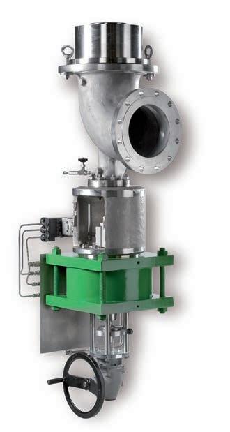
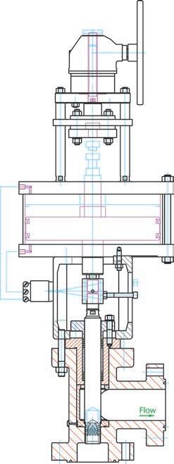
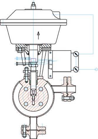
Angle Control Valves – Model 74
The SchuF Model 74 Angle Control or Choke Valve is designed for critical or severe applications involving level control and pressure letdown in High Pressure Acid Leach (HPAL), Hydrocracking, Coal Liquefaction, PTA and other demanding processes.
Available in sizes from 1 inch to 36 inches and up to ASME 2500# as standard, SchuF can address almost any size or pressure class. Materials of construction include cast or forged Carbon or Stainless Steel, Hastelloy, Inconel and Titanium bodies with ceramic or tungsten carbide trim components for handling flashing slurries of 2 0 % solid content and above.
The SchuF Angle Control Valve is often custom made to process requirements in order to optimise field performance. Valve bodies are simulated to extend service life, by preventing impingement of particles on internal surfaces. Stagnant areas are minimized to prevent build up of slurry or scale.
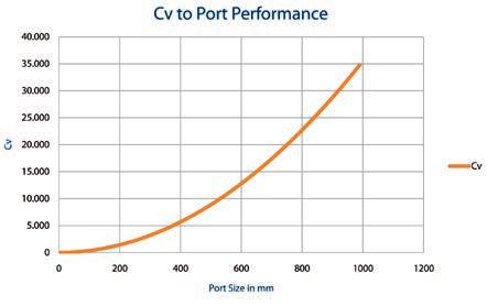
SchuF Control valves optimise Cv to port performance.
Key Angle Control Valve Features:
Accelerating Flow Path:
Acceleration of abrasive process media is maintained continuously through a sweeping, non-expanding angle body to prevent flashing until the fluid, gas or slurry enters the protected outlet area. There is no stagnant space where process slurry can form eddies or undesired turbulence.
Cv Sizing for 3 Phase Flow:
SchuF’s proprietary Cv sizing model is particularly well adapted to three phase flow media.
Large Stem Diameter:
Stem diameters are individually sized to eliminate deflection and the possibility of damage to critical trim components.
Replaceable Valve Seat:
The ability to change the customised valve seat reduces downtime and saves money.
Unique Flow Characteristics :
Linear and equal percent control characteristics are available as standard. Customers can opt for SchuF‘s patented X 3 bell curve for better control at known operating levels.
Anti-Rotation Device:
The yoke includes a device to stop the valve stem from turning when the valve plug is subjected to high velocity lateral fluid flow.
Cast Yoke:
Rugged yoke bracket in cast stainless or carbon steel is used to prevent structural deformation when the valve is mounted in non-vertical positions.
Cavitation & Flashing Solutions:
Please see the flashing and cavitation highlight on page 17 and 18 respectively.
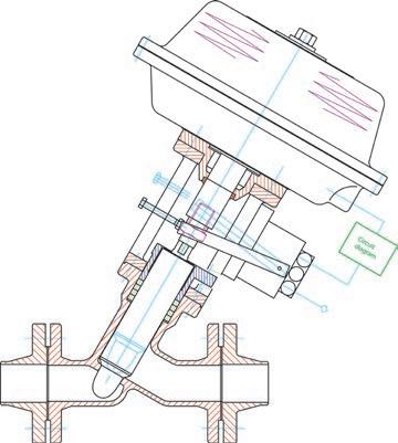
In-Line Control Valves – Model 50R
The Y-globe control valve can be installed in process lines from 1 inch to 24 inches and is ideal to control flow or to reduce pressure. It has a sturdy design, superior flow and control characteristics (compared to globe or ball control valves) and zero leakage sealing performance.
Addressing Fugitive Emissions
SchuF has extensive experience in stuffing box design to minimize emissions to the work area. Typical packing options include PTFE and Graphite with a lantern ring for early leakage detection. A proprietary wiper ring design prevents migration of slurry into the stuffing box area. These elements can be applied to most of the SchuF control valve range.
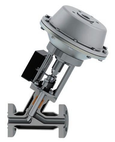
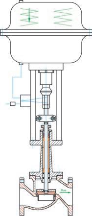
Globe Control Valve – Model 72
Globe control valves combine the protection of a bellows seal with the contr ollability and leak tightness of a SchuF control valve. They are used in arduous and lethal services with critical media such as chlorine, phosgene, hydrofluoric acid, NH 3 , CO 2 , urea etc. They are Eurochlor compliant.
Globe control valves are available in sizes from 1“ up to 24 “, ASME 150# to 900#, in long or short bellows design, in carbon steel, stainless steel, Hastelloy, Monel and Titanium, with pneumatic or electrical controls. All electrical equipment can be explosion proof.
Common SchuF Angle and In-line Control Valve Features:
Accelerating body geometry design
Optimised 3 phase flow calculation
Linear, equal % and SchuF bell X 3 control curve
Integral plug and stem
Ideal to let down high pressure over several stages and avoid cavitation
2 , 3 or up to 6 staged pressure reduction disc design
Up to ASME 2500# as standard
True Equal % characteristics
High Cv values (1 to 3000)
Large outlet chamber to reduce velocities
Seat leakage to Class VI, API 598 or EN 60534-4
Standard robust yoke construction
Inlet angle 4 5°, 6 0 ° or 9 0°
DN 25 ( 1”) to DN 900 (36”)
Disc opening direction eliminates plugging by catalyst fines or other sediments
Cast or single block forged body available
Easy to replace severe service trim
Ideal for energy dispersion and noise control
Multi hole cage or labyrinth design – to achieve accurate flow characteristics and noise attenuation
Class VI (API 598) shut-of f is achieved, eliminating unacceptable leakage
Linear or Equal % control characteristics
Available with fast opening actuators, and smart positioners
Easy to replace trim parts
Stainless steel or special hard metal materials can be used
Multi-S – Model 7 4M
Cage Release – Model 74K
Multi-S – Model 74MS
In-Line Control Valves
Y-Globe Control Valve – Model 50
Ideal for in-line control with bubble tight positive shut-off
High throughput (e .g. 4 “ (DN 100) –Cv min 140 to max 300)
Flow optimised – low pressure drop
Equal %, linear or custom control characteristics
Class VI process shut-off and zero leakage to atmosphere performance
Dead and slow space free options
Wafer Control Valve – Model 76
Ideal for limited space control applications
Space saving design
Cost optimised
Linear or equal %
1/ 2 inch to 3 inch
To ASME 2500#
Globe Control Valve – Model 72
Ideal for lethal service control applications
Designed for at least 20,000 operations
Emergency stuffing boxes as standard
Linear, equal % or o n/ off control
Bellows fitted in bonnet to protect against erosion
Control disc or cage (for noise reduction)
Loose self aligning disc for absolute shut-off, (ASME Class VI)
Metallic sealing surfaces with different hardness (e .g. stelliting)
Control Valves
Control Valve Flashing Solutions
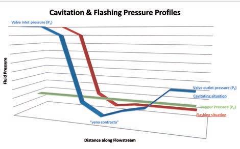
Control valves used in applications involving liquids in high pressure or high pressure drop conditions are highly susceptible to damage from flashing or cavitation.
Flashing occurs in the liquid flow when the internal pressure of the liquid falls below the vapour pressure and remains below it. During this phase vapour bubbles form and flow with the liquid downstream at increased velocities causing erosion to valves and piping.
Whilst the variables (P 2 and Pv – see above diagram) that define flashing are not directly controlled by the valve, the best approach for flashing medium is to choose control valves that minimise its effects. SchuF provides a number of anti flashing control features:
Particle Impact Prevention
The SchuF Model 74BS is an accelerating flow angle body design with flow to open characteristics. Installed in a tank or vessel the outward opening disc moves any potential flashing to the exit seating area of the valve. Flashing then takes place outside of the valve and the kinetic energy is dissipated into a special tank or vessel.
Velocity Reduction
Valves with expanded flow areas downstr eam of the vena contracta are beneficial as the erosive velocity is reduced. SchuF’s angle control valve range either as a flow to open –
X-Flash, or flow to close – ToughFlash (for pipeline installation, where the plug rises into the body) design can be provided with an expanding choke tube or customised outlet. This allows pr essure to increase and minimises velocity.
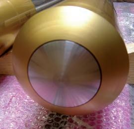
Hardened Materials & Surfaces
Correct selection of both the body and trim material can go a long way to r educing the effects of flashing and cavitation. The synergetic effects of erosion and corrosion in flashing water applications (water corrosion of the steel and flashing erosion of the resultant soft oxide layer for example) can be minimised by selecting a low alloy steel. For more complex flashing media, a wide choice of hard trim materials from ceramic to tungsten carbide, stelliting or surface coatings are available to protect the valve.
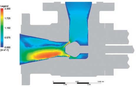
Simulation is at the heart of control valve design for difficult applications. Many negative process consequences such as flashing, crystal formation, or sediment deposits are either avoided or accommodated in SchuF control valve design through extensive use of FEA and CFD (ANSYS) simulation.
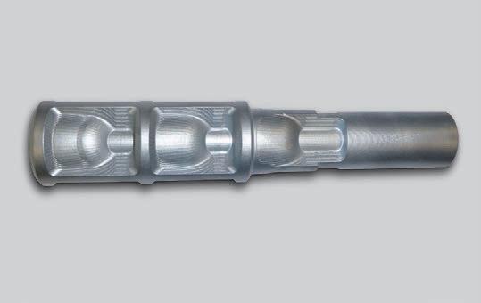
Piston head with tungsten carbide coating
Control Valves
Cavitation
Cavitation occurs in a similar way to flashing with the formation of gas bubbles as the liquid pressure falls below vapour pressure. If the liquid pressure then recovers and rises above the vapour pressure the bubbles start to collapse or implode creating a shock wave which releases energy in the form of multiple micro jets.
Valve Sizing and Design
Micro jets have a velocity of 400 km per hour and temperatures of up to 5,50 0°C and literally blast away pieces of the valves components or lead to severe pitting and accelerated corrosion. Cavitation is typically accompanied by accentuated hydrodynamic noise and vibrations in the valve and piping.
Anti-Cavitation Solutions
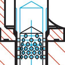
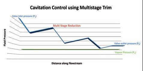
Pressure Drop Management
The best means to eliminate cavitation is to control the pressure drop and ensure that it never falls below vapour pressure.
This is achieved by using a multiple stage trim that reduces the pressure drop in stages. The principle is illustrated in the above diagram, where pressure is let down in three successive stages. SchuF has a broad range of multistage trims that allow pressure to be let down in up to six stages in a step plug, or more in a stacked cage design.
Proper valve sizing and body or trim design are also important factors in fighting cavitation. SchuF has specialised in the more complex dual and triple phase medium, typically slurries, and has developed its own advanced Cv sizing model for them. The model takes into account pressure drops at minimum, normal, and maximum flows as well as full details of inlet pressure and fluid conditions. The results are referenced against empirical data collected over the past 40 years in exact or similar applications and result in design recommendations for valve, seat and outlet size, body and trim material, as well as trim design for flashing or cavitating applications.
Control Valve Diversity
As a result of its focus on real life field contr ol issues SchuF has designed a broad range of both in-line and angle valves. These valves are suitable for critical services as well as severe services that exhibit flashing and cavitation. All SchuF control valves exhibit the following key benefits:
Key Benefits
Proven critical reliability
Special design options
Longer valve life
Lower maintenance
Three stage control plug example
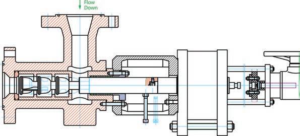
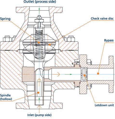
Automatic Recirculation Valve (ARV) – Model 78
Automatic recirculation valves have the primary purpose of protecting centrifugal pumps by assuring minimum flow through the pump at all times.
Purpose
They replace conventional multi valve pump protection solutions which have proven to be costly or inefficient. The automatic recirculation valve approach unites the check valve, the automatic bypass control valve and pressure letdown functionality in a single valve body.
Mode of Operation
The automatic recirculation valve is installed in the pump discharge line in the position of the main check valve that it replaces. The valve opens as soon as the pump builds sufficient flow to move the internal valve disc in the main line into an open position. Decreasing flow thought the valve causes the spring loaded disc to return to its seat closing the process outlet. At the same time the bypass outlet is uncovered allowing a minimum flow of liquid to be routed back to the pump.
Key Features:
Standard sizes up to 16 ” (DN 400) and ASME 4500#
Automatic bypass operation
Non return function
Modular design
Custom pressure letdown in bypass
No power or air pressure required
Offshore design available
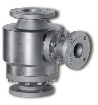
ARV Product Range
SchuF Fetterolf has a broad range of ARV designs to meet most applications. The SureFlo TM design is suitable for line sizes up to 10” and ASME 2500# pressure class. The HighFlo TM goes to 24 ” and ASME 4500#, whilst the ControlFlo TM is more suitable for high pressure applications where multistage letdown or enhanced bypass sealing is required.
ARV Pump Applications
General centrifugal pumps
Boiler feed water pumps
Cooling plant feed pumps
Crude oil pumps
Fluid gas pumps (LNG, LPG etc.)
Process liquid pumps
Booster pumps
Seawater injection pumps
Fire fighting pumps
SureFlo TM design