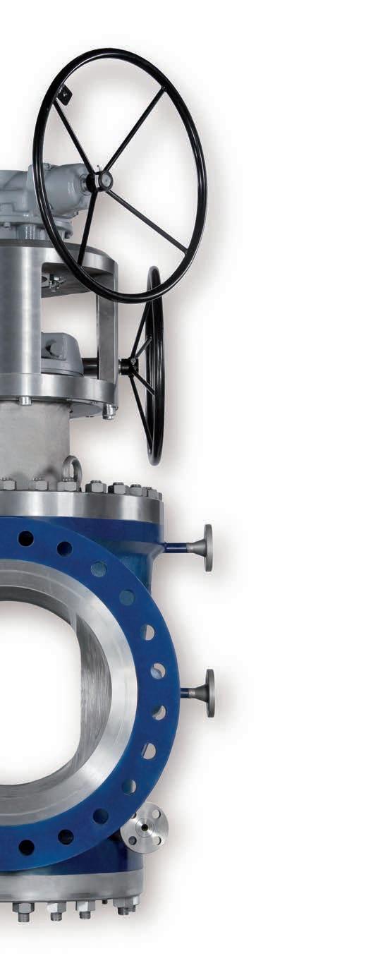
SchuF Fetterolf Valve Portfolio

Company Profile
“Every SchuF valve is an innovation in itself”
Wolfgang Frank Chairman, SchuF Fetterolf Group
For over 100 years SchuF valves have stood for innovation and quality at the highest level.
Together with our customers, we invent, design and manufacture valves customised to exact tolerances, processes or special operating conditions. SchuF Fetterolf valves can be found in standard and in many severe service applications in the Chemical, Polymer, Pharma, Oil, Gas, Offshore and Refining industries.
… Innovation
The invention of the Lift Plug valve in 1911 and piston & disc bottom outlet valves in the nineteen twenties by the founder of SchuF – Josef Frank – wer e the first of a long line of valve inventions and innovative designs. Continuing research and development in materials (used in valve bodies and trim), design as well as complex processes enable SchuF today to offer valve solutions for applications with high pressure, high temperature and difficult media; or a combination of all three.
The integration of Fetterolf Corporation in 2004 further broadened the Group’s product portfolio, innovation and geographical reach. Today the SchuF Fetterolf product line includes control, isolation, sampling, switching and safety related valves.
… Quality
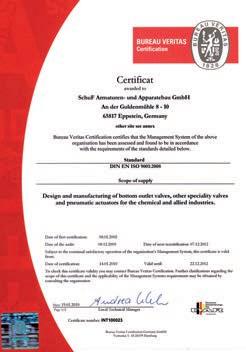
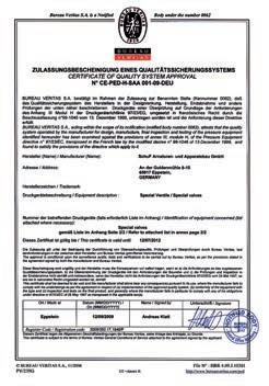
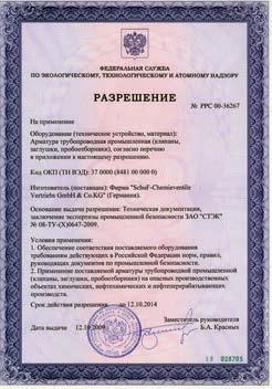
The exceptional quality and longevity of SchuF Fetterolf valves is a result of the precise attention to process detail, creative design, and the use of the appropriate high quality materials. In addition to its own high internal company standards, SchuF is ISO 9001, GOST and PED certified and can manufacture according to ASME, DIN, NACE, API, Fire Safe, GMP, JIS or any other internationally recognised standard.
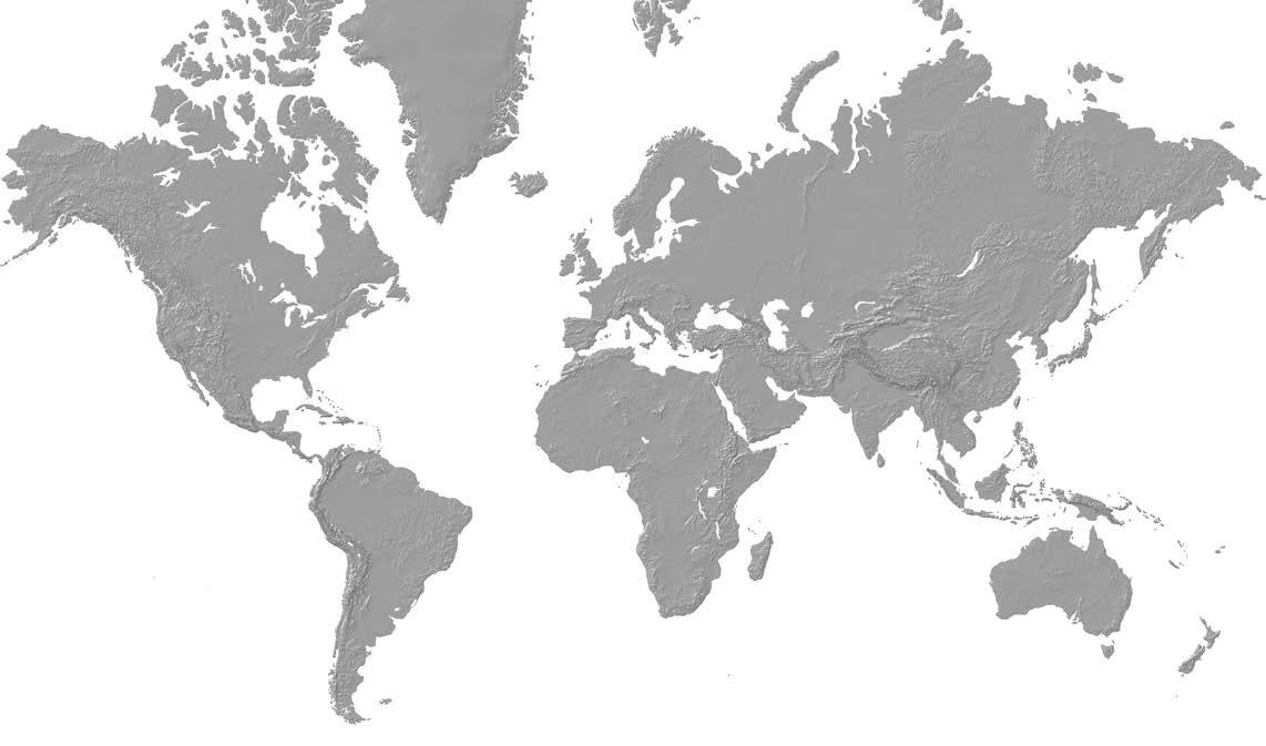
… Worldwide presence
SchuF Fetterolf is represented in over 65 countries worldwide and has design and production facilities in Germany, Ireland, India, Italy, the United States and the United Kingdom.
Bottom Outlet and Drain Valves
SchuF invented the first industrial class bottom outlet valve 100 years ago. Today SchuF Fetterolf offers tank bottom valves with a disc or piston design in almost any material, pressure class or size and with many options.
Disc Bottom Outlet Valves (DBOV) –Model 18 / 19 / 24 / 25
Application
Disc bottom outlet valves are commonly used in Pharmaceutical and Fine Chemical pr ocesses to drain or feed non-viscous media from vessels or reactors. Reactor considerations such as the position of internal mixing equipment and the nature of the media determine the need to use a disc lowering or disc rising valve variant.
An additional benefit of the latter is that the formation of crust is automatically removed when the disc is moved to the open position.
Compact Valve Build
A short stroke disc valve is ideal where space is limited or weight is a concern. Smaller, lighter and faster actuators can be used.
Dead Space Free
SchuF drain valves are designed to ensure that the vessel and the valve itself drain completely. There are no spaces for matter to accumulate.
Crust Breaking
For media containing crystals or crust forming substances, certain ram and disc valves offer the ability to clear any blockage and ensure problem free flow.
Zero Emissions to Atmosphere
Disc valves can be fitted with a metal or PTFE extruded bellows or a PTFE Diaphragm. Leakage of toxic or flammable substances are eliminated. Key Advantages for
All Disc and Ram valves are available in sizes from 1"(DN25) to 24"(DN600) and up to ASME 2500 pressure class as standard. The outlet angle can be 45°, 60° or 90°.
Fire Safe design
CIP (Clean in Place)
Temperature sensing
Wide choice of material
GMP designs
PTFE or glass lining
Heating jacket
Disc grinding
Flushing connections
Leak detection
Flush bottom outlet valves can also be used for feeding, injection or sampling applications. Special designs are available for critical processes or media such as slurries. SchuF valves are customised to meet your exact equipment or process needs.
Piston Bottom Outlet Valves
Fast Draining
Full bore unimpeded flow piston valves are ideal to quickly drain reactors, tanks or pipelines.
Diverse Sealing Options
Metal to metal or soft seal in the valve body, vessel or with an extend-ed sleeve ensure the right sealing characteristics for different process requirements. Please see page 6.
Super Closure
Super Closure is a self adjusting mechanism, that ensures a constant bubble tight seal to atmosphere.
Customised Design
Every SchuF valve can be customised to match the exact specification of the vessel, reactor or tank. Material and instrumentation can also be customised for specific plant requirement.
Replaceable Valve Seat
The ability to easily change the customised valve seat reduces downtime and saves money.
Customised design, larger nominal bore and higher pressure classes are available on request.
High corrosion resistant coatings
Full automatic control
Internal/External polishing
Hard facings
Contoured pistons
Position and safety sensors
Manual, pneumatic, hydraulic or electric actuation
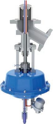
Ram Bottom Outlet Valves (RBOV) –Model 26 / 28
Application
Piston bottom outlet valves are used to quickly drain or feed vessels or reactors. They are normally full bor e. For these reasons piston BOVs are favoured for processes with viscous media. They clean the valve body with each piston stroke and optionally can clear crust or scale around the vessel outlet.
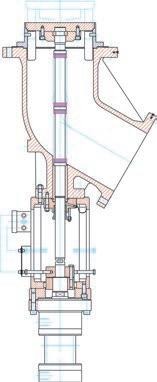
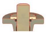
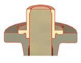
Ram drain valve –Model 28KR
Rod Seal drain valve –Model 26FR
Detail: Soft Seal in the vesselDetail: 26FR – Super Closure
Bottom Outlet and Drain Valves
Flush Bottom Outlet Valve Examples
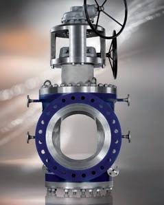
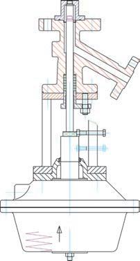
Hydraulic Actuated Disc Valve – Model 25BH
Features & Benefits:
Powerful space saving hydraulic actuation
Rising disc with automatic crust breaking
Metal bellow seal for zero emissions
Ideal for higher pressure or temperature applications
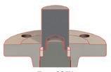
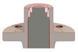
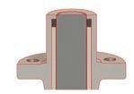
Sealing Method Options
Custom Fit Seat Sealing Options

MultiProbe™ Valve – Model 25BX
Features & Benefits:
Infrared (IR) reaction monitoring for Process Analytical Technology (PAT) applications
Integral IR and temperature sensor in one stem and disc
Equipped with a unique and patented sealing system
Short Stroke Ram Valve – Model 28KS
Features & Benefits:
Short stroke valve with pneumatic actuation
Ideal where space is limited but fast draining and injection is required
Integrated Seat Sealing Options
Disc Lowering Valve with Diaphragm – Model 24BM
Features & Benefits:
Zero leakage to atmosphere with diaphragm inside the valve body
Flushing connection for in service cleaning
Typically used in Pharmaceutical applications
Model 28KV
Model 28KR
Model 28KS
Model 28FX
Model 28FS
26FR
Sampling Valves
Sampling Valves
Many chemical and pharmaceutical processes need to be regularly tested during processing to ensure consistent product quality. SchuF Fetterolf sampling valves enable trouble free and safe content sampling of pipelines, reactors, tanks and storage vessels without product loss or cross contamination.
Product Range
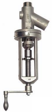
Screw-in Sampling Valves – Model 32
Screw-in or flanged to pipelines, reactors or vessels
Size up to 11/ 2 “ and ASME 600#
Available with different flange and seat options
Materials: carbon steel, stainless steel and most alloys
Diverse sealing options include:
Metal Seated Ram (32PG)
Metal Seated Disc (32PT)
Ram PTFE Seal Rings (32FR)
Metal Seated Ram with PTFE Seal Ring (32FG)
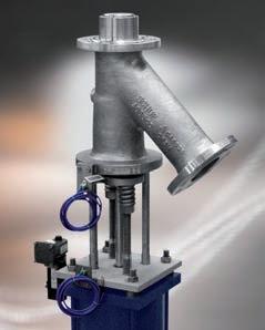
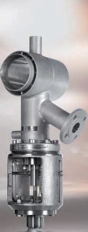
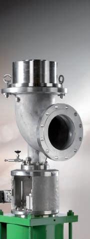
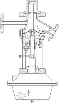
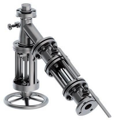
Core Pipe Assembly – Model 30
Sampling valve with an integral cor e pipe assembly & heating jacket
Sampling under high temperature and pressure up to ASME 2500#
Vertical or horizontal installation
Contoured ram options
Customised assemblies to match your exact sampling requirements
A full brochure is available at: www.schuf.co m/ pdf
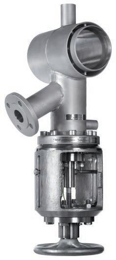
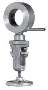
Wafer Sampling Valves –Model 31
Sampling valve with integral flange insert
Flange insert is installed into the product line
Insert size up to 12“ and ASME 600#
Available with any Model 32 sealing options
Key Features:
Robust construction for longer valve life
Dead space free, non clogging design
Class V or VI shut-off
Standard designs ar e stocked, customised design on demand
Heating jacket and optional outlet legs
Fire safe design according to ISO 10497
Customised sampling systems for many applications such as:
Fixed volume sampling under high pressure and temperature
Sampling with zero leakage to the atmosphere
Wet or dry powder sampling
Visual checks through sight glasses
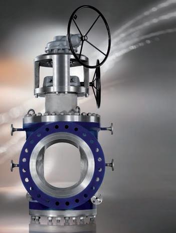
Isolation Valves
Lift Plug Valve – Model 12
SchuF invented the Lift Plug Valve in 1911. It is the original double block and bleed (DB & B) isolation valve.
Applications
Lift plug valves are primarily used to isolate or switch media flow, but are particularly suitable for severe applications at high temperatures or with highly abrasive or clogging media. Some process and media examples include:
Delayed coking
Acetic acid
Urea
Cement
Polymers
Liquid sulphurs
Chlorine gas
Power industry
Design
The lift plug valve consists of a few key parts – body, plug and an actuating device. There are no sealing rings, bellows or gaskets that can break, clog or fail.
Operation
During operation the valve plug is lifted and turned from open to close via a lift-turn-reseat mechanism that can be actuated manually or using an electric, pneumatic or hydraulic actuator. In the open or closed position, there is no gap between the plug and the valve body where the fluid and its contents can settle, contaminate or score the valve.
Key Features:
Size: 1” (DN25) to 36 ” (DN900)
Pressure Class: all to ASME 2500#
Full bore plug design
Protected valve seat (PVS)
Integral double block and bleed
Dual motor actuation
3 line Sediment Defence System (SDS)
Integral flushing
Benefits
Ideal for high temperature & dirty media
Smooth turn non-stick plug
Dead space free
Sediment free – 3 line defence system
Easy to maintain
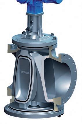
TruEPlug Valve – Model 11
The Tru EP lug is a special rotary plug valve that achieves true Double Block and Bleed (DB&B) service in one enclosed valve body. It belongs to the SchuF family of lift plug isolation valves invented in 1911.
Applications
The Tru EP lug is suitable for isolation of mostly clean media at moderate temperatures (to 25 6° C) where seal tight closure is essential.
Typical applications include:
Tank storage isolation
Meter stations
Loading/Unloading terminals
Fire suppression system isolation
Branch line isolation
Operation
The Tru EP lug has a simple yet efficient design with few pieces. The key parts include the body, bonnet, plug, seals and actuator. The plug has a special moving insert or shield that is fixed to the central plug and has an inlaid soft sealing ring.
As the plug lifts and rotates from the open to the closed position, clearance is maintained between the plug shield and the valve body, allowing free movement and avoiding scoring.
As the plug enters its closing position it is lowered forcing the plug shield against the body and thereby initiating a soft seal. In the closed position the plug shields are effectively expanded (the reason why the valve is sometimes refered to as an E xpanding P lug valve).
The soft seal is further compressed until a metal to metal seal is achieved.
This double mechanical sealing mechanism gives the Tru EP lug one of the most reliable leak tight seals available.
Key Features:
1” to 42 ” and up to ASME 900#
Replaces traditional two valve and spool piece DB & B arrangement
Reduced bore or full bore piggable
Positive shut-off double seal
Abrasion-free plug movement
Bleed function proves zero leakage
Metal to metal seal in the open position
Manual, electric or pneumatic actuation
Fire Safe option
Benefits
Quick and easy operation
Cost effective DB &B
Zero leakage
Easy maintenance
TruEPlug Seal Shield
Isolation Valves
Y & P Pattern Globe Valves – Model 50
SchuF Fetterolf provides globe type isolation valves in a Y, P, and Straightway pattern. They offer class V or VI shut off and are ideal to replace leaking or clogging ball valves or where bubble tight shut-off is essential.
Application
Globe valves are widely used to isolate process lines where the pressure drop across the valve needs to be minimised without sacrificing sealing performance. All SchuF Fetterolf globe valves meet or exceed these criteria.
Key Features – Y & P Globe Valves:
Size: 1” (DN25) to 24 ” (DN600)
Pressure class: up to ASME 4500#
Low pressure drop (delta P)
Zero leakage to atmosphere
Dead space free options
Positive shut-off
Roddable and piggable designs
“Straightway” Y-Globe Valve
The straightway valve was designed to deliver Class V & VI, as well as API standards for zero leakage. It has the patented Ram-Seal mechanism which utilises a dual metal seal plus a PTFE seal ring encircling a solid plunger.
It distinguishes itself as a fully roddable valve with the lowest Delta P values available.
It is commonly installed in refineries, petrochemical and nuclear power plants (e g. in radioactive waste applications).
SchuF Fetterolf Straightway Valve
The new P-Globe straightway valve has been designed for applications that require intermittent pigging. It incorporates the optimal pressure drop and sealing characteristics of the globe valve and a full bore unimpeded flow path. It is also bi-directonally piggable.
Options
In addition the Y-Globe, Straightway and P-Globe valves are available with many options – disc grinding in slurry or crystal forming applications, heating jackets to ensure the optimal temperature medium flow, bellows for a positive seal to atmosphere, vacuum yokes and many flow control features.
Benefits
No leakage; clog free
Optimal flow characteristics
Man safe isolation
Full bore, unimpeded flow path
„P“ Globe Valve
SchuF Fetterolf Y-Globe Valve
SchuF Fetterolf P-Globe Valve
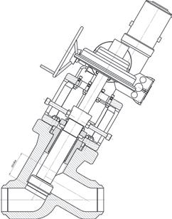
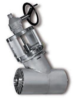
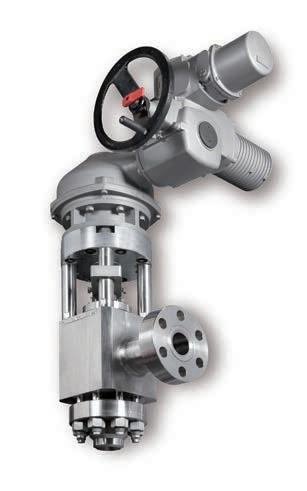
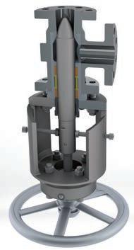
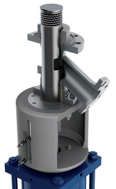
High Pressure Angle Valve – Model 71
High pressure angle valves are typically used to isolate process flow where the medium is under high pressure (200 bar +). In these circumstances media properties partially change dramatically and valves need to withstand corrosion and erosion due to high pressure, cavitation, flashing, crystal formation and vibrations to name a few.
Application
The SchuF high pressure (HP) angle valve is used in several industries including polymer, ure a /carbamate, power generation, fertilizer, and oil & gas.
Key Features:
Size: 1” (DN25) to 20 ” (DN500)
Up to ASME 2500# and above
Single piece polished plug & spindle
One piece body and heavy yoke
Exchangeable front and back seats
Back seating – enhances seal to atmosphere and pr otects the spindle
Class V or VI seal to process
Top or side entry for easier maintenance
SchuF applies its flashing and cavitation prevention and avoidance expertise to ensure lower maintenance and extended valve life. This includes a combination of valve design (angle design or customised outlet), simulation, material choice (e .g. Ferralium 255 for trim parts), and 100 years of valve experience in many extreme processes.
Blowdown Valves – Model 50 / 71
Blowdown valves are used to remove impurities from boilers or their associated pipelines in order to maintain boiler integrity and efficiency.
Application
Intermittent blowdown allows for the removal of alkaline earths, phosphates or polyacrylates that can form a sludge layer at the bottom of the boiler. If not removed, a dangerous insulating scale layer can form on the heating surfaces, and reduce heat transfer. Regular, intermittent blow down for a few seconds removes this safety risk. SchuF provides both intermittent and continuous blowdown valves in both angle and Y-globe valve designs.
Key Features:
DN15 to DN50 and up to ASME 1500#
Single piece plug and spindle
Both disc and seat are hard faced with Stellite for erosion resistance
Linear or multistage control trim option for high pressure let down
Manual or pneumatic actuation
Spring to close for rapid blow down
Back seating option
Lever option for rapid operation
Continuous blowdown is the most effective blow down operation. Dissolved solids are removed in a continuous process so that the minimum quantity of water is discharged from the boiler.
Benefits
Rugged compact design
Improved blowdown effectiveness
Insensitive to water-hammer effects
Longer life and availability
Control Valves
Control valves work to keep a process variable such as flow or pressure within a predefined operating range. They are often the last piece of equipment in a process loop that can compensate a load disturbance and are therefore considered critical valves.
Custom Applications
SchuF’s experienced design engineers provide you with unique valve designs to meet both usual and unusual process demands. Special application designs, in service worldwide and showing continuous satisfactory performance, include:
Discharge and feed flow control valve in PET , PVC , PP & PE reactors
Level, pressure & steam injection control valves in PTA processes
Level control of flashing fluid in coal liquefaction or heavy oil upgrading
Feed and level control for gasification according to the Siemens, Lurgi, GE and Shell process licences
Flow control of powder in fine chemical & pharmaceutical processes
High precision multi-port flow control of highly viscous, non linear, non-Newtonian polymer fluids
Discharge flow control valve for urea reactors where urea grade stainless steel is mandatory
Fully jacketed short body wafer control valves, for Nylon and PC production
Mineral processing applications such as high pressure acid leaching ( HPAL )
Sour water and Amine letdown in several refinery processes
Resurge and flare control for gas
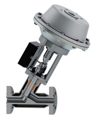
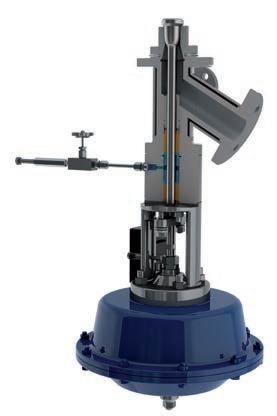
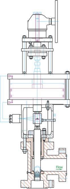
Angle Control Valves – Model 74
The SchuF Model 74 Angle Control or Choke Valve is designed for critical or severe applications involving level control and pressure letdown in High Pressure Acid Leach (HPAL), Hydrocracking, Coal Liquefaction, PTA and other demanding processes.
Available in sizes from 1 inch to 36 inches and up to ASME 2500# as standard, SchuF can address almost any size or pressure class. Materials of construction include cast or forged Carbon or Stainless Steel, Hastelloy, Inconel and Titanium bodies with ceramic or tungsten carbide trim components for handling flashing slurries of 2 0 % solid content and above.
The SchuF Angle Control Valve is often custom made to process requirements in order to optimise field performance. Valve bodies are simulated to extend service life, by preventing impingement of particles on internal surfaces. Stagnant areas are minimized to prevent build up of slurry or scale.
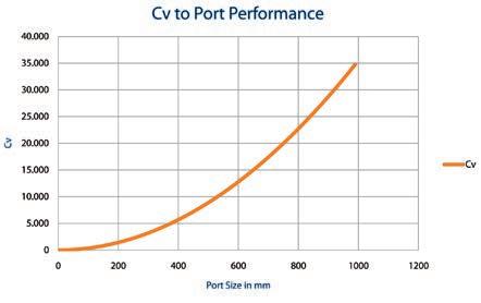
SchuF Control valves optimise Cv to port performance.
Key Angle Control Valve Features:
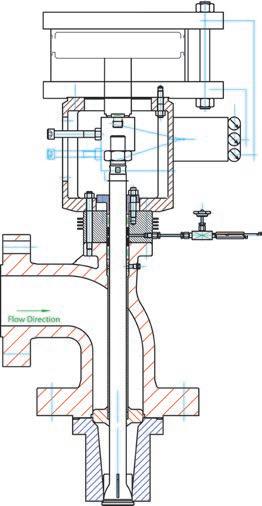
Accelerating Flow Path:
Acceleration of abrasive process media is maintained continuously through a sweeping, non-expanding angle body to prevent flashing until the fluid, gas or slurry enters the protected outlet area. There is no stagnant space where process slurry can form eddies or undesired turbulence.
Cv Sizing for 3 Phase Flow:
SchuF’s proprietary Cv sizing model is particularly well adapted to three phase flow media.
Large Stem Diameter:
Stem diameters are individually sized to eliminate deflection and the possibility of damage to critical trim components.
Replaceable Valve Seat:
The ability to change the customised valve seat reduces downtime and saves money.
Unique Flow Characteristics :
Linear and equal percent control characteristics are available as standard. Customers can opt for SchuF‘s patented X 3 bell curve for better control at known operating levels.
Anti-Rotation Device:
The yoke includes a device to stop the valve stem from turning when the valve plug is subjected to high velocity lateral fluid flow.
Cast Yoke:
Rugged yoke bracket in cast stainless or carbon steel is used to prevent structural deformation when the valve is mounted in non-vertical positions.
Cavitation & Flashing Solutions:
Please see the flashing and cavitation highlight on page 17 and 18 respectively.
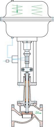
In-Line Control Valves – Model 50R
The Y-globe control valve can be installed in process lines from 1 inch to 24 inches and is ideal to control flow or to reduce pressure. It has a sturdy design, superior flow and control characteristics (compared to globe or ball control valves) and zero leakage sealing performance.
Addressing Fugitive Emissions
SchuF has extensive experience in stuffing box design to minimize emissions to the work area. Typical packing options include PTFE and Graphite with a lantern ring for early leakage detection. A proprietary wiper ring design prevents migration of slurry into the stuffing box area. These elements can be applied to most of the SchuF control valve range.
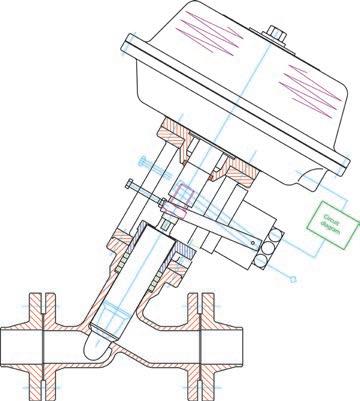
Globe Control Valve – Model 72
Globe control valves combine the protection of a bellows seal with the controllability and leak tightness of a SchuF control valve. They are used in arduous and lethal services with critical media such as chlorine, phosgene, hydrofluoric acid, NH 3 , CO 2 , urea etc. They are Eurochlor compliant.
Globe control valves are available in sizes from 1“ up to 24 “, ASME 150# to 900#, in long or short bellows design, in carbon steel, stainless steel, Hastelloy, Monel and Titanium, with pneumatic or electrical controls. All electrical equipment can be explosion proof.
Angle Control Valves
The SchuF control valve product range consists of angle as well as in-line control valves. SchuF has developed over 20,000 control valve variations in its hundred year history. Each has its own specific characteristics tailored to the process control elements that are most important for it – pressure, level, flow or temperature.
X-Flash – Model 74BS
Ideal for avoiding flashing in the valve
Flow to open – External Flashing
Single stage letdown design
High Cv values (1 to 3000)
Low wear and tear
Disc opening direction eliminates plugging by sediments
Best suited for vessel installation
Tough Flash – Model 74CS
Ideal to accommodate flashing in the valve
Flow to close
Hard material trim
Flashing occures in the protected seat / choke tube area
Up to 180 bar let down is possible in a single stage
Customised and replaceable choke tube
Suitable for pipeline or vessel installation
Common SchuF Angle and In-line Control Valve Features:
Accelerating body geometry design
Optimised 3 phase flow calculation
Linear, equal % and SchuF bell X 3 control curve
Integral plug and stem
Ideal to let down high pressure over several stages and avoid cavitation
2 , 3 or up to 6 staged pressure reduction disc design
Up to ASME 2500# as standard
True Equal % characteristics
High Cv values (1 to 3000)
Large outlet chamber to reduce velocities
Seat leakage to Class VI, API 598 or EN 60534-4
Standard robust yoke construction
Inlet angle 4 5°, 6 0 ° or 9 0°
DN 25 ( 1”) to DN 900 (36”)
Disc opening direction eliminates plugging by catalyst fines or other sediments
Cast or single block forged body available
Easy to replace severe service trim
Ideal for energy dispersion and noise control
Multi hole cage or labyrinth design – to achieve accurate flow characteristics and noise attenuation
Class VI (API 598) shut-off is achieved, eliminating unacceptable leakage
Linear or Equal % control characteristics
Available with fast opening actuators, and smart positioners
Easy to replace trim parts
Stainless steel or special hard metal materials can be used
Multi-S – Model 7 4M
Cage Release – Model 74K
Multi-S – Model 74MS
In-Line Control Valves
Y-Globe Control Valve – Model 50
Ideal for in-line control with bubble tight positive shut-off
High throughput (e .g. 4 “ (DN 100) –Cv min 140 to max 300)
Flow optimised – low pressure dr op
Equal %, linear or custom control characteristics
Class VI process shut-off and zero leakage to atmosphere performance
Dead and slow space free options
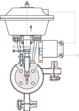
Wafer Control Valve – Model 76
Ideal for limited space control applications
Space saving design
Cost optimised
Linear or equal %
1/ 2 inch to 3 inch
To ASME 2500#
Globe Control Valve – Model 72
Ideal for lethal service control applications
Designed for at least 20,000 operations
Emergency stuffing boxes as standard
Linear, equal % or o n/ off control
Bellows fitted in bonnet to protect against erosion
Control disc or cage (for noise reduction)
Loose self aligning disc for absolute shut-off, (ASME Class VI)
Metallic sealing surfaces with different hardness (e .g. stelliting)
Control Valves
Control Valve Flashing Solutions
Control valves used in applications involving liquids in high pressure or high pressure drop conditions are highly susceptible to damage from flashing or cavitation.
Flashing occurs in the liquid flow when the internal pressure of the liquid falls below the vapour pressure and remains below it. During this phase vapour bubbles form and flow with the liquid downstream at increased velocities causing erosion to valves and piping.
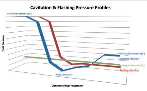
Whilst the variables (P 2 and Pv – see above diagram) that define flashing are not dir ectly controlled by the valve, the best approach for flashing medium is to choose control valves that minimise its effects. SchuF provides a number of anti flashing control features:
Particle Impact Prevention
The SchuF Model 74BS is an accelerating flow angle body design with flow to open characteristics. Installed in a tank or vessel the outward opening disc moves any potential flashing to the exit seating area of the valve. Flashing then takes place outside of the valve and the kinetic energy is dissipated into a special tank or vessel.
Velocity Reduction
Valves with expanded flow ar eas downstream of the vena contracta are beneficial as the erosive velocity is reduced. SchuF’s angle control valve range either as a flow to open –
X-Flash, or flow to close – ToughFlash (for pipeline installation, where the plug rises into the body) design can be pr ovided with an expanding choke tube or customised outlet. This allows pressure to increase and minimises velocity.
Hardened Materials & Surfaces
Correct selection of both the body and trim material can go a long way to reducing the effects of flashing and cavitation. The synergetic effects of erosion and corrosion in flashing water applications (water corrosion of the steel and flashing erosion of the resultant soft oxide layer for example) can be minimised by selecting a low alloy steel. For more complex flashing media, a wide choice of hard trim materials from ceramic to tungsten carbide, stelliting or surface coatings are available to protect the valve.
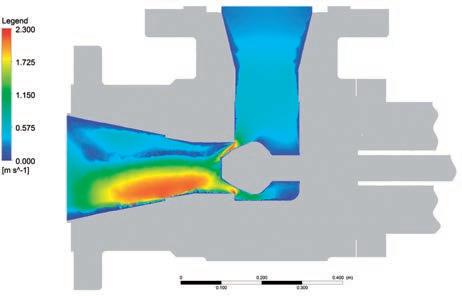
Simulation is at the heart of control valve design for difficult applications. Many negative process consequences such as flashing, crystal formation, or sediment deposits are either avoided or accommodated in SchuF control valve design through extensive use of FEA and CFD (ANSYS) simulation.
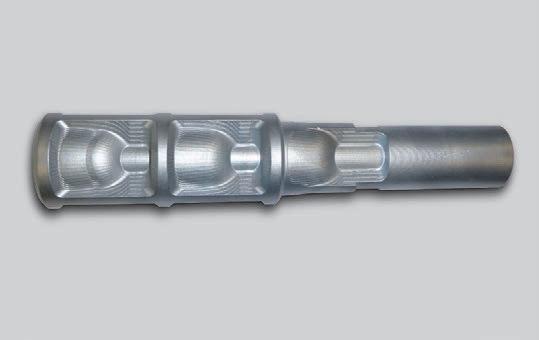
Piston head with tungsten carbide coating
Control Valves
Cavitation
Cavitation occurs in a similar way to flashing with the formation of gas bubbles as the liquid pressure falls below vapour pressure. If the liquid pressure then recovers and rises above the vapour pressure the bubbles start to collapse or implode creating a shock wave which releases energy in the form of multiple micro jets.
Valve Sizing and Design
Micro jets have a velocity of 400 km per hour and temperatures of up to 5,50 0°C and literally blast away pieces of the valves components or lead to severe pitting and accelerated corrosion. Cavitation is typically accompanied by accentuated hydrodynamic noise and vibrations in the valve and piping.
Anti-Cavitation Solutions
Pressure Drop Management
The best means to eliminate cavitation is to control the pressure drop and ensure that it never falls below vapour pressure.
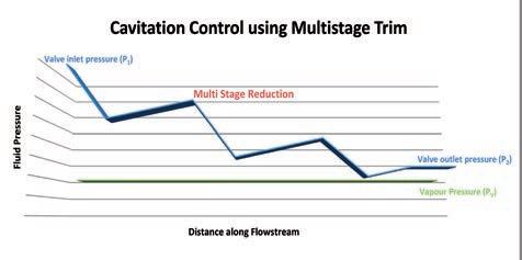
This is achieved by using a multiple stage trim that reduces the pressure drop in stages. The principle is illustrated in the above diagram, where pressure is let down in three successive stages. SchuF has a broad range of multistage trims that allow pressure to be let down in up to six stages in a step plug, or more in a stacked cage design.
Proper valve sizing and body or trim design ar e also important factors in fighting cavitation. SchuF has specialised in the more complex dual and triple phase medium, typically slurries, and has developed its own advanced Cv sizing model for them. The model takes into account pressure drops at minimum, normal, and maximum flows as well as full details of inlet pressure and fluid conditions. The results are referenced against empirical data collected over the past 40 years in exact or similar applications and result in design recommendations for valve, seat and outlet size, body and trim material, as well as trim design for flashing or cavitating applications.
Control Valve Diversity
As a result of its focus on r eal life field control issues SchuF has designed a broad range of both in-line and angle valves. These valves are suitable for critical services as well as severe services that exhibit flashing and cavitation. All SchuF control valves exhibit the following key benefits:
Key Benefits
Proven critical reliability
Special design options
Longer valve life
Lower maintenance
Three stage control plug example
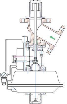
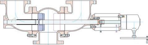
Automatic Recirculation Valve (ARV) – Model 78
Automatic recirculation valves have the primary purpose of protecting centrifugal pumps by assuring minimum flow through the pump at all times.
Purpose
They replace conventional multi valve pump protection solutions which have proven to be costly or inefficient. The automatic recirculation valve approach unites the check valve, the automatic bypass control valve and pressure letdown functionality in a single valve body.
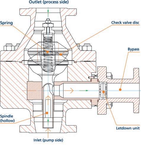
Mode of Operation
The automatic recirculation valve is installed in the pump discharge line in the position of the main check valve that it replaces. The valve opens as soon as the pump builds sufficient flow to move the internal valve disc in the main line into an open position. Decreasing flow thought the valve causes the spring loaded disc to return to its seat closing the process outlet. At the same time the bypass outlet is uncovered allowing a minimum flow of liquid to be routed back to the pump.
Key Features:
Standard sizes up to 16 ” (DN 400) and ASME 4500#
Automatic bypass operation
Non return function
Modular design
Custom pressure letdown in bypass
No power or air pressure required
Offshore design available
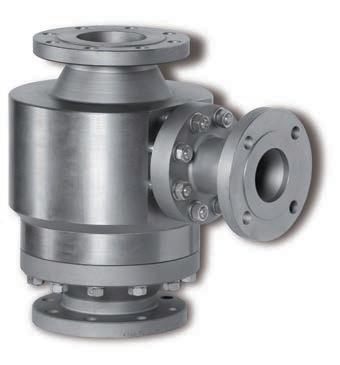
ARV Product Range
SchuF Fetterolf has a broad range of ARV designs to meet most applications. The SureFlo TM design is suitable for line sizes up to 10” and ASME 2500# pressure class. The HighFlo TM goes to 24 ” and ASME 4500#, whilst the ControlFlo TM is more suitable for high pressure applications where multistage letdown or enhanced bypass sealing is required.
ARV Pump Applications
General centrifugal pumps
Boiler feed water pumps
Cooling plant feed pumps
Crude oil pumps
Fluid gas pumps (LNG, LPG etc.)
Process liquid pumps
Booster pumps
Seawater injection pumps
Fire fighting pumps
SureFlo TM design
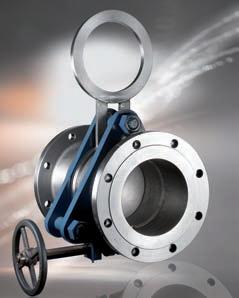
Switching Valves
Diverter Valves – Model 4 0- 49
The diverter valve is a part of the SchuF Fetterolf family of switching valves. Diverter valves split, switch, combine or isolate process media into one or more streams. They can have multiple inlets or outlets or can be bi-directional.
Dead and Slow Space Problems
Dead or slow spaces can lead to many unwelcome consequences. In plastic and polymer production, the end product can be contaminated by particles from previous batches rendering it worthless. In the refinery, dead space can lead to accumulation of coke like particles, catalyst fines or clumps which reduce line capacity and eventually require significant line back flushing.
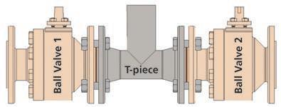
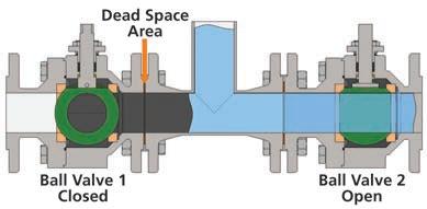
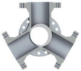
Traditionally, isolation valves interconnected with T-piece piping are used to isolate the process flow in one direction. This is often achieved by using two ball valves and a T-Piece as shown above.
When one of the ball valves is closed and the medium contains solid particles or highly viscose liquids a ‚Dead Space‘ is created by the medium in and around the ball valve and in the left section of the T-piece. The dead space area is shown in the above diagram.
Once the second ball valve is opened, part of the residue that filled the dead space will stick to the piping, thus reducing the full through bore and over time require the valve to be removed for maintenance. Alternatively the residue will form clumps that over time break away to damage other equipment downstream or contaminate the next product batch.
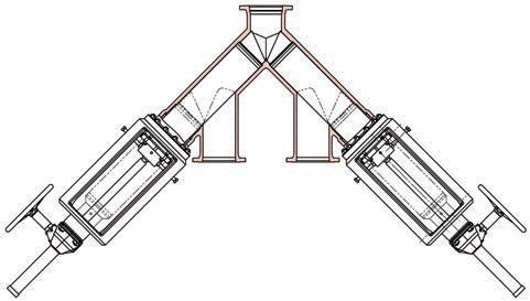
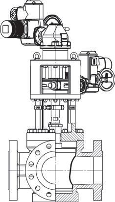
The Diverter Alternative
In the example below a fluid or gas enters the diverter valve through one or more inlets and is either routed to one outlet (the second outlet being isolated), or to both outlets.
This is achieved by two actuated pistons or discs that move into the valve body and cover all or part of the outlets from either side. This action results in a completely dead space free valve. The valve is for all intents and purposes a seamless extension of the plant piping
Key Features:
Sizes: 1” to 24 ” (larger on request)
ASME 150# to 2500# as standard
3 , 4 , 5 or multiple inlets/outlets
Diverse body designs (Y, T, R & S) to match plant piping needs
Metal to metal positive sealing
Control characteristics & contoured piston options
Heating jacket options
Optional integral flushing ports
Due to their excellent flow properties and in particular the avoidance of slow or dead spaces, diverter valves are ideal for processes with viscose or particle rich media.
A full brochure is available at: www.schuf.co m/ pdf
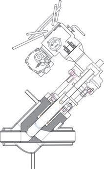
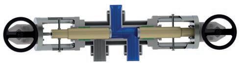
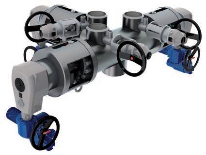
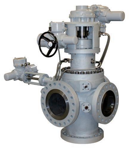
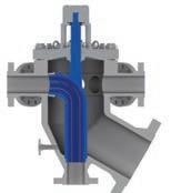
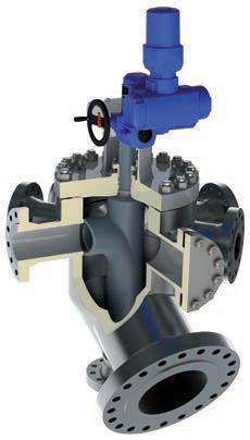
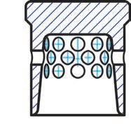
3-Way Diverter Valve – Model 42TK
2.Cross sectional drawing of 1.
1.Ball Valve and T-piece arrangement
Diverter Valve Examples
3 Way Y Type – Model 40YK
Used in a PBT resin application
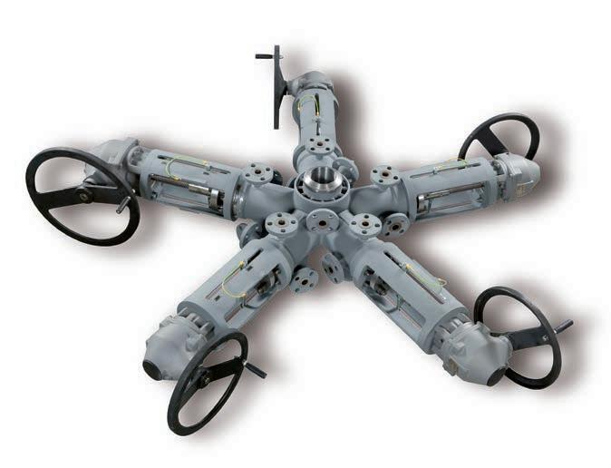
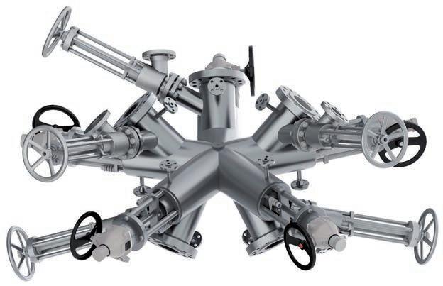
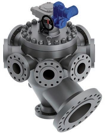
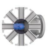
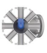
6 Way Star Design – Model 42 FK
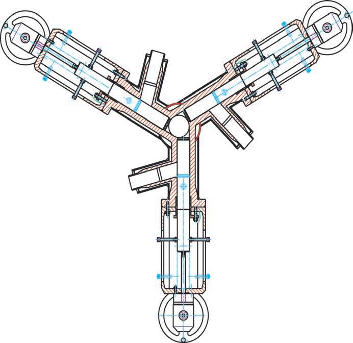
4 Way Tangential Star Design –Model 47
Used in a PET application
Used in a Polycarbonate application
4 Way Type – Model 42DK
Used in a PTA application
5 Way Special – Model 49
Used in a heavy oil upgrading application
Switching Valves
SwitchPlug TM Valve – Model 12SP
The SchuF SwitchPlug valve is a switching valve with typically three outlets and one inlet. It is used to switch media flow from one outlet to another in a defined sequence whilst isolating all other outlets.
It is commonly used in the refining industry for delayed coking due to its leak tight metal to metal sealing characteristics and suitability to high temperatures.

The SwitchPlug consists of only a few moving parts – body, plug and actuator – and is therefore highly reliable. There is no gap between the plug and the valve body where the fluid or coke particles can settle, damage piping or score the valve. Flushing is therefore only required while the plug is in motion.
Key Features:
Size: 6 ” (DN 150) to 24 ” (DN600)
Pressure Class: ASME 1 50# to 1500#
2 , 3 , or 4 or more outlets
Full bore round plug design
High throughput during switching
Dual motor actuation
3 line Sediment Defence System (SDS)
Integral flushing options
Benefits
Coking Defence System – the SwitchPlug is designed to outperform conventional valves (e.g. ball valves) in services where sediments or coke particles can collect and cause equipment failure. The combination of the gap free design, integrated drain valves and distributed and tangential flushing ensure optimal coke free valve operation.
Y or T design – SchuF can provide the SwitchPlug in either a Y (12 0 °) or T (9 0°) configuration. This allows for greater piping flexibility, particularly in existing plants or for revamps. The SwitchPlug can also be mounted in horizontal or vertical positions.
Dual Actuation – the SwitchPlug opertes with two actuators – one to lift or lower the plug and a second one to rotate it to the required position. The lower torque requirement leads to longer actuator life, reduces maintenance and eliminates plug sticking.
Flow Regulation Mechanism –the SwitchPlug actuators are provided with an integral control system. This ensures both accurate positioning of the plug to the outlets or bypass line –time and time again. It also enables proportionate distribution of the coke media between two lines or drums e g. 7 0 % / 30 %. Greater than 90 % of the flow throughput can be realised even in these intermediate positions.
4-Way SwitchPlug Valve
Y configuration, inlet below
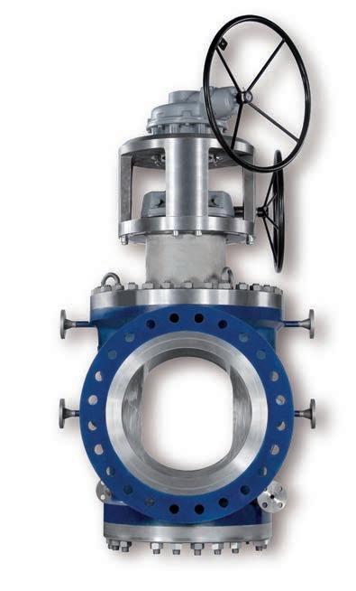
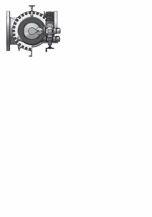
ManiFlow Selector Valve TM – Model 48SZ
The ManiFlow Selector Valve (MSV) has been specifically developed for oil field applications where oil or gas from multiple wells are brought together into one valve body for testing and analysis. Typically the flow from seven wells are connected, but only one is routed via a special plug selector to a test outlet.
The other six are commingled and exit via a large production outlet. Once the first well has been tested, the next or any in a desired sequence of the connected wells can be tested.
Specification
The MSV is available with up to eight inlet ports, one test port and one production outlet. Standard sizes include: 2”/ 4”, 3”/ 6”, 4”/ 8”, 4” / 10” and 6” / 16” in all ASME classes to 1500#. All body materials can be provided with cladding, typically in Incoloy 825. For sour services the lower body half can be in solid Incoloy 825 material. A diverse range of sealing material and options such as flushing ports, locking devices, electronic controller and push button stations are available.
Custom Solutions
SchuF has applied 50 years of diverter and switching valve experience and extensive simulation to solve some of the critical problems found in conventional selector valves and manifolds. These include valve body corrosion, cross contamination between the test and production flows due to leakage, and emissions to atmosphere.
Key Features:
Compact, modular design
LeakTight, spring loaded seal
Field adjustable sealing arrangement
1. 0 ° to 1. 5 ° Plug position accuracy
3 stage packing for low emission
Electric actuation, bi-directional
36 0 ° operation, multi- or part turn
Clear user friendly controls
Integral digital display
Local, remote or Modbus control
Removeable hand wheel
Benefits
The SchuF MSV has been designed to reduce the size of pipe manifold arrangements, comprising only one valve and one actuator.
In addition the SchuF MSV offers:
Customised simulation & design
Longevity – special material combinations that reduce body pitting corrosion
Superior sealing design that eliminates leakage into the test outlet
Simplified in-line maintenance
*all wetted parts according to NACE MR0175 or equivalent; leakage class IV; fire safe design on request
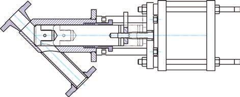
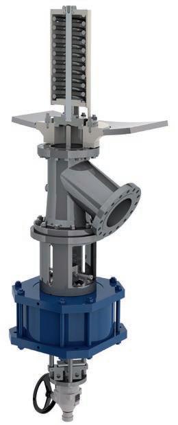
Spray Rinse & Injection Valves
Spray Rinse Valve – Model 27SR
The Fetterolf Spray rinse valve was developed to wash residue from large tank or reactor walls without having to open or enter a vessel. This feature has two key benefits: safety of personnel for applications with toxic fluids and to reduce cleaning time in batch processes.
Application
Spray rinse valves can be used to clean vessels after each batch operation. Water, steam, solvents and anti-sticking agents can be injected and are sprayed in a distinct and efficient pattern into the vessel. This leads to longer uninterrupted reactor production cycles and the most cost efficient use of cleaning agents. They are also used in vessel rinsing applications with toxic media in order to ensure personnel safety.
Spray rinse valves are frequently found in the Plastics & Polymer (especially PVC), Fine Chemicals and Pharmaceutical industries.
Mode of Operation
In operation, the spray tube assembly is moved out of the valve body to initiate the spray and retracts back into the valve body after the washing cycle. In the closed position the valve disc is flush with the end of the valve body and the spray head is tightly sealed off from the process – and remains clog free.
The device efficiently performs the dual functions of:
1.Shut-off and control of the spray water
2.Direction of the spray in a varying pattern to attain complete wash-down of the residue
The valve can also be used to distribute anti sticking agent.
Key Features:
Standard sizes 3 / 4 ” up to 2 ” (DN50) and ASME 900#
Customised spray pattern, pressure & volume
Zero leakage to atmosphere and process –dual Ram seal design
Exchangeable seat and spray head
No clogging guaranteed, due to backflow prevention mechanism
Rotating or linear spray head
Electric or pneumatic actuation
Optional position switches
Rinsing Valve Product Range
Fetterolf provides both a rotary and a linear spray rinse design, with many features customisable to the application requirement.
Benefits
Increased batch process productivity
Reduced maintenance
Protection against toxic emissions
Optimised water & solvent consumption
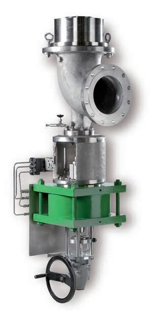
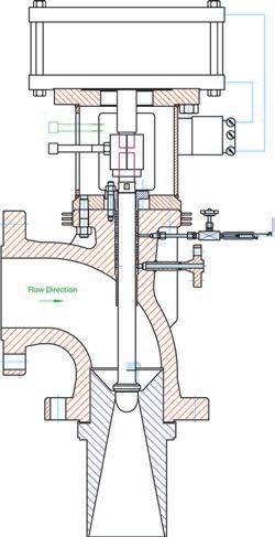
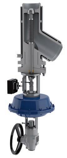
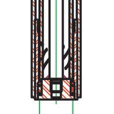
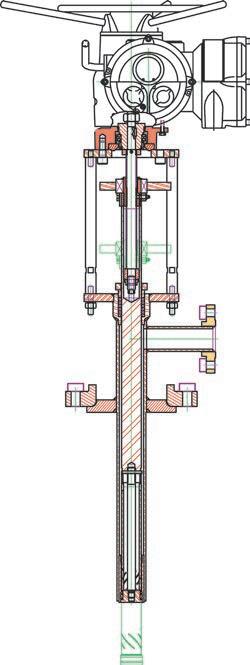
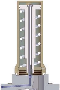
Steam Injection Valves – Model 27SE
Steam injection valves are primarily used in the Chemical, Pharmaceutical and Petrochemical industries. They are used to inject steam or any gas into a reactor or vessel.
Application
There are two common applications:
1.Direct and quick pre-heating of media an d/ or vessels
2.Steam stripping and sanitisation to remove monomers or impurities in polymerisation processes
The choice of a piston or disc injection valve design is process and media driven:
A solid piston design is suitable for full bore, high flow rate applications with vibrations.
Disc style injection valves are more suitable where space is limited, the required flow rate is low or where low or zero emissions to atmosphere are important.
Key Features:
Piston or disc valve design
Metal to metal sealing
Replaceable seat and injection head
Customised arrangement of holes for any required gas or vapor injection
Non clogging
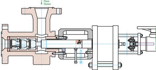
Operation
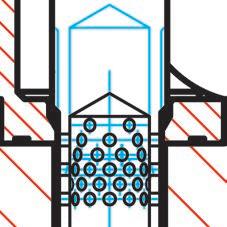
The valve is typically installed at the bottom of a vessel. Steam is injected into the inlet, flows through the hollow injection stem and exits through up to 2000 dispersion holes.
Constant steam pressure ensures that there is no back-flow and keeps the dispersion holes free of sediment build up.
The valve operates according to a linear step control curve characteristic. This allows a predetermined number of hole rings to be exposed as required by the process.
Benefits
Time saving vessel pre-heating
Evenly distributed steam pattern
Step-linear flow rate control
Optimised steam usage
Avoids steam hammer effects
27SE Piston injection valve with hollow piston and up to 2000 holes for high flow rates
27SE Disc injection valve with injection head
tional bellows for zero lea
kage to atmosphere
Safety Related Valves
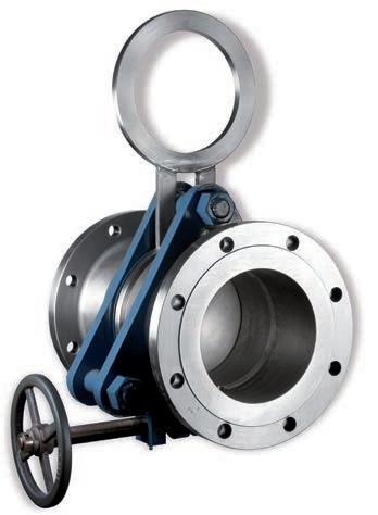
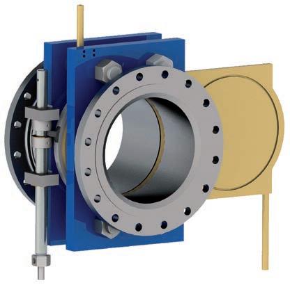
Line Blind Valves – Model 81
The ability to isolate pipelines in order to avoid leakage and product cross contamination and to ensure the safety of personnel working on downstream equipment is an essential procedure in industries that store, forward or process hazardous chemical or hydrocarbon substances. Valves can leak downstream. Line blinds do not.
The SchuF Fetterolf Cam-Set ® is an advanced line blind system that assures absolute positive line isolation in a convenient, fast and safe way.
Key Features:
Absolute positive shut-off
Size up to DN1500 (60“)
ASME 150# to ASME 2500#
Vast selection of seal types and materials
Counter weights for larger sizes
Special coatings for corrosive environments
Special Offshore design
Applications
Cam-Sets are used in the chemical, petrochemical, refining, paper and pulp and offshore industries. The most common process applications are:
Flare stack maintenance
Hydrocarbon pump or loading stations
Storage terminal isolation
FPSO, oil & gas tanker and merchant fleet
Branch line isolation of flammable, corrosive or toxic media
Blast furnace gas lines
Design Criteria
Cam-Sets are built in strict accordance to international standards such as the ASME
Boiler & Pressure Vessel Code – section 8, API 590 (ASME 16.48), API 598, ISO 9001 and – wher e appropriate – NACE MR0175 and API 221 7. Personnel and plant safety are our greatest concern.
Product Range
Schuf Fetterolf has a range of line blinding systems – the swing type or Cam-Set, the sliding type or Cam slide, and the Stacey line blind for dusty or clogging media (such as coal, minerals and slurries).
Benefits
One man, one side operation
Fast change – less than 60 seconds
No flange or line spr eading
No special tools or crane required
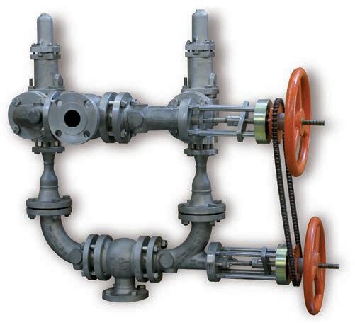
Changeover Valves – Models 6 0- 69
Changeover valves enable users to switch process flow from one line to a second line during continuous plant operation. They are primarily used as part of plant safety dual relief systems and are typically installed with pressure relief valves or rupture discs.
They enable maintenance and repair to be carried out safely without disrupting on-going plant operation. The valves are designed to make it impossible to shut off both valve outlets at the same time as required by the ASME Boiler & Pressure Vessel Code.
Key Features:
Size: 1” (DN25) to 14 “ (DN350)
Up to ASME 2500#
Rising / non rising stem design
Class V or VI process seal
Low pressure drop (< 3%)
Multiple packing configurations
Continuous system overpressure protection
Temperature range -6 0 ° to 70 0°C
Applications
Changeover valves are primarily located on storage tanks or vessels commonly found in refineries, chemical, petrochemical, or pharmaceutical processing plants. In addition to dual relief in closed discharge systems, they are used in the following applications:
Switching to & from dual filtration systems
Selecting between multiple heat exchangers
In pumping or fluid transfer systems
Switching from one process line to another
In manifolding applications
Tandem Changeover Valve
The tandem changeover valve allows for simultaneous selection of the appropriate pressure relief valve and corresponding discharge into a single outlet of a dual relief valve system. One changeover valve is mounted on the riser (inlet) and the other on the outlets of the relief valves. The valves are operated simultaneously through a mechanical chain wheel or rod link.
The linkage between the two pressure relief valves is simple, effective and provides positive and simultaneous switching.
Changeover Valve Options
Contoured discs to avoid dead spaces
Bellows seal option for zero emissions to atmosphere
Hardened seat materials e g. stelliting
Can be partially or fully jacketed
Chain wheel operator for remote locations
Benefits
Reduces plant downtime
Improves process safety
Reduced pressure drop
Fast and easy operation
Tandem Changeover Valve – Model 69
Safety Related Valves
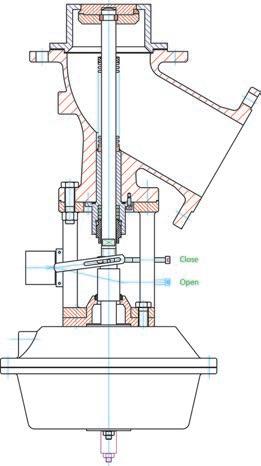
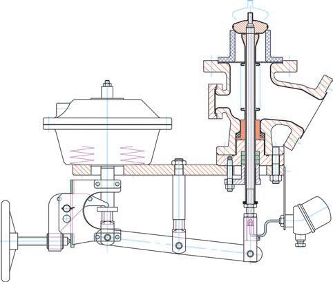
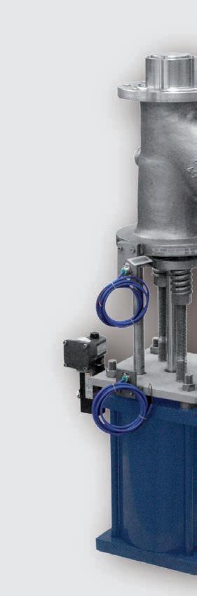
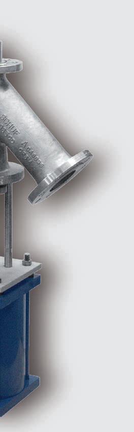
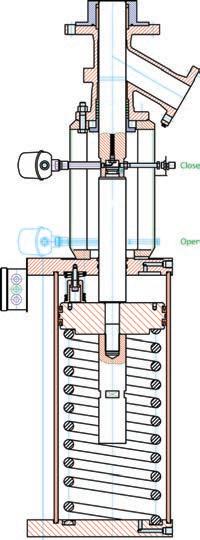
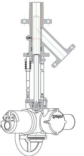
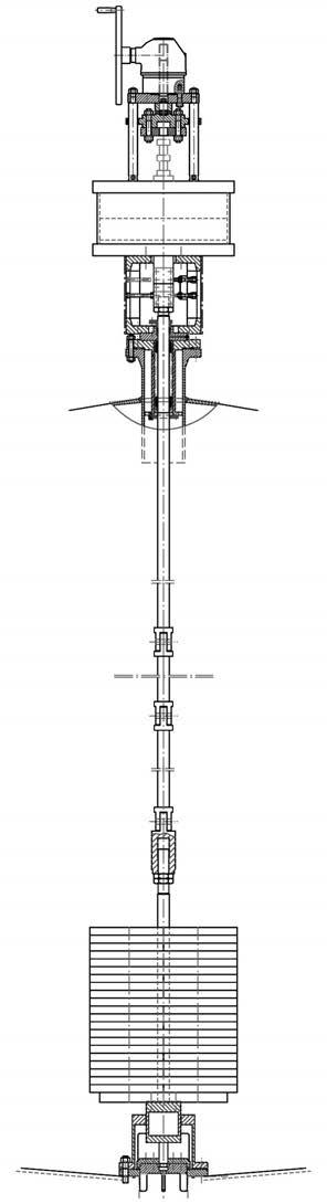
Tank Emergency Shut-Off Valves (TESO) – Models 29 and 73
TESO valves protect large storage tanks in emergency circumstances. They are commonly used in tanks containing toxic or flammable fluids.
Under normal operation conditions the valve is held open by air pressure and in the event of an emergency (e .g. an earthquake or fire) a spring or weight closes the valve.
In-lying TESO valves – Model 73
Installed from top to the bottom of the tank
A long spindle connects the pneumatic actuator and disc or plug valve at the bottom
In case of an emergency a heavy weight moves the disc or plug downwards closing the valve
73BH – In-lying disc safety valve
73ID – In-lying plug safety valve
73IS – Compact TESO design
73IS Compact TESO design
TESO for tank side installation
Extended valve seat bridges the space between the inner and outer tank walls
73IH – Side mounted safety disc valve for double wall tanks
TESO Valves – Key Features:
The in-lying valve seat is unaf fected by damage to pipework or to the valve itself
Valves can have bellows sealed spindles
Automatic opening by air pressure
Suitable for cryogenic services such as liquefied gases
TESO for tank bottom installation –Model 29BH
Valve seat welded into the vessel bottom
In emergency cases the spring inside the vessel closes the valve
The valve disc – that is flush with the tank outlet – is detachable from the valve spindle which is outside the tank wall. This ensures a tight seal even if the outer parts of the valve are damaged
Optionally with an extended pad seat
Product Portfolio Overview
SchuF Fetterolf has delivered over one million valves during its 100 year history to a wide variety of industries in over 50 countries worldwide. Headquartered near Frankfurt in Germany, the company has additional design and manufacturing centres in Italy, India, Ireland, UK and the USA.
Drain & Sampling Valves
Piston Bottom Outlet Valves
Disc Lowering / Rising Bottom Outlet Valves
Custom Bottom Outlet Valves
Screw-in, Line & Wafer Sampling Valves
Control Valves
Isolation Valves Angle Control Valves
Lift Plug Valves
TruEPlug Valve
Y-/ P-Globe & Straightway Valves
High Pressure Angle Valve
Special Gate Valves
Multistage Control Valves
Cage Control Valves
In-line Control Valves
Automatic Recirculation Valves
Key Client List:
AkzoNobel
AstraZeneca
BASF
Bayer
BP
Chevron
Clariant
DOW Chemical
Du Pont
Eastman
Evonik
Exxon Chemical
FCFC
Far Eastern
Foster Wheeler
GE
Glaxo Smith Kline
INEOS
Invista
Jiangsu Hengli
Lanxess
LG Chemical
Linde
Lukoil
Lurgi
Merck
Novartis
Oerlikon
Oxy Vinyls
Pemex
Petrobras
Pfizer
The SchuF group has sales and agent offices covering almost every country in the world. We manufacture valve products that control, isolate, divert, and sample liquids, gases, powders, and slurries. Our product range of engineered, customised valves includes:
Switching Valves
Y, R & T type Diverter Valves
Multiway Diverter Valves
SwitchPlug Valve
ManiFlow Selector Valve
Custom Diverter Valves
Reliance
Roche
SABIC
Saipem
Salavat
Samsung
Sandoz
Sanofi Aventis
Shell
Shin Etsu
Sinopec
Sulzer
Temex
Tuntex
Uhde
Vinnolit
Spray Rinse & Injection Valves
Spray Rinse Valve
Steam Injection Valve
Safety Related Valves
Line Blind Systems
Changeover Valves
Emergency Tank Shut-off Valves (TESO)
Customised Valves