

Spring Cylinder Rotary Actuators

These instructions must be read prior to installing, operating, and maintaining this equipment.

These instructions must be read prior to installing, operating, and maintaining this equipment.
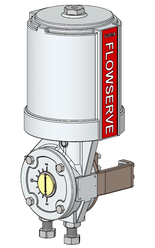
The Valtek® VR combines high torque and pneumatic stiffness with excellent throttling capabilities. These characteristics are designed into a lightweight, rugged, and compact assembly, making the Valtek rotary actuator the foremost choice for quarter-turn applications. The Valtek rotary actuator is designed to operate the Valdisk high-performance butterfly valve, the Shearstream V-notch ball valve, Maxflo Eccentric Rotary plug control valve or other applications requiring precise rotary motion. Valtek pneumatic and electro-pneumatic positioners are available for throttling applications.
The Valtek VR actuator, cylinder and positioner are designed for supply pressures up to 150 psi (10.3 bar) for sizes VR25, VR50, VR100 and 80 psi for VR200 (5.5 bar), making very high torques attainable. The actuator uses a rocking piston for direct conversion of linear motion to rotary motion. The rocking piston assembly combined with a splined shaft and lever eliminates lost motion. The following instructions are designed to assist in unpacking, installing, and performing maintenance as required on Flowserve Valtek VR.
This instruction manual does not include specific product design data. Such data can be found on the actuator’ s specification documents; additionally, dimensional information can be found in the Valtek VR technical bulletin. Procure needed documents as necessary before you begin any work on the valve.
User Instructions cannot deal with all possible situations and installation options. It is required that only trained and qualified technicians are authorized to adjust, repair or work on Valtek VR, positioners, and other accessories. Review this bulletin prior to installing, operating, or performing any maintenance on the actuator. Additional Installation, Operation, and Maintenance Instructions (IOMs) cover other features (such as positioners and other accessories)
To avoid possible injury to personnel or damage to actuator parts DANGER, WARNING, CAUTION and NOTICE indicators must be strictly followed. Modifying this product, substituting non-factory parts or using maintenance procedures other than outlined could drastically affect performance and be hazardous to personnel and equipment and may void existing warranties. This manual should be used in conjunction with applicable local and national laws. Failure to comply with User Instructions will render the manufacturer’s guarantee and liability null and void. Unless otherwise agreed, the manufacturers near terms and conditions of sale shall apply.

The following information covers the Valtek VR
For Valdisk, MaxFlo and ShearStream valves
• Size 25 Square inches
• Size 50 Square inches
• Size 100 Square inches
• Size 200 Square inches
Comes with or without ancillary equipment

Valtek VR are pressure vessels designed and rated for specific application conditions. Before installation, check the serial number and / or the tag number to ensure that the valve and actuator being installed are correct for the intended application. Do not use the valve assembly outside of its rated pressure / temperature limits Exceeding the design limits may cause hazardous conditions including leakage of the process media or rupture of the pressure boundary resulting in possible process loss, equipment or environmental damage, or serious personnel injury or death.
The Valtek VR handles a wide variety of general service applications.
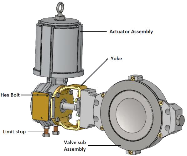
The Valtek VR consists of the cylinder, transfer case, yoke and connecting parts. The actuator is designed with a high level of interchangeability allowing the user to assemble the greatest possible number of variations from a minimum number of components to match each application. There are two fail safe positions, close or open, without or with handwheel.
The Valtek VR is designed for use in MODERATE and WORLDWIDE environmental conditions, ambient temperature range -40°F to 350°F (-40°C to +177°C) and pressures up to 150 psi (10.3 bar) for sizes VR25, VR50, VR100 and 80 psi for VR200 (5.5 bar), unless restricted by the accessories. The product offering may include optional ancillary equipment, such as positioners, air-filter regulators, solenoid valves, limit switches or boosters. Digital, I/P, or pneumatic positioners can be mounted with a mounting bracket. Refer to the relevant manufacturer‘s user instructions for information regarding other ancillary equipment.
The Valtek VR actuators are generally delivered as tested and assembled units
Unauthorized modification of the Valtek VR actuator voids the product test certification and product warranties, could drastically affect product performance, and could be hazardous to personnel and equipment.
Before Valtek VR re-use, all necessary tests must be repeated and recorded in compliance with all test routines, guidelines, and engineering standards.
Safety terms – DANGER, WARNING, CAUTION and NOTICEare used to highlight specific dangers and / or provide additional information that may not be readily apparent in the User Instructions.

DANGER Indicates that death, severe personnel injury and/or substantial property damage will occur if proper precautions are not taken.
WARNING indicates that severe personnel injury, death, and substantial property damage can occur if proper precautions are not taken.


CAUTION Indicates that potential injury (minor or moderate) else equipment damage can occur if proper precautions are not taken.

NOTICE indicates practices or provides additional technical information.
Valtek VR actuators are available in below listed spring configurations.
1. VR25, VR50 are available in the standard and extended spring configurations.
2. VR100, VR200 are available in standard and dual spring configurations. or
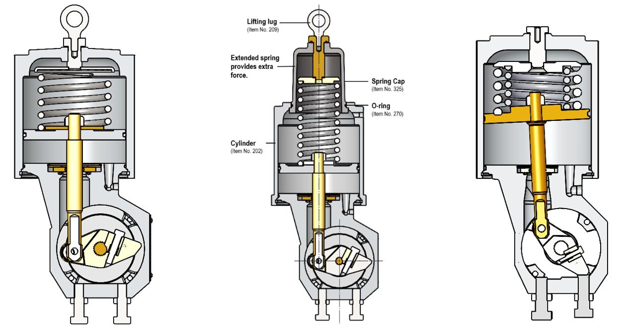
Do not lift or support extended spring cap while lifting the entire valve, this can cause the O-ring to slip and result in leakage. The lifting lug on spring cap should be used for lifting only the actuator after dismantling from valve body.
For applications, where unusually high spring thrusts are required, Flowserve offers the Valtek VR extended spring for sizes VR25, VR50 actuators and dual springs for sizes VR100, VR200 actuators.
Using many of the same design concepts as the Valtek VR extended spring actuator offers external spring cap. This allows for extra-long springs which provide extra force. The Valtek VR standard, extended spring and dual actuator section view as shown in Figure 1: A, B and C
Pay close attention to shipping marks and transport pictograms.
Careful packing, loading and transport arrangements are required to prevent products from being damaged during transport. Standard packaging includes a cardboard box, with or
without a wooden pallet base as needed. Special packaging may include a wooden box. Packaging may use cardboard, plastic wrap, foam, or paper as packing material. Filling material may be a carton type or paper.
Shipping marks display product and package dimensions and weight (for further information see Packaging and Sending Instructions, Form L 002). Packing guidelines for export follow HPE standards. (Nonreturnable packaging may contain up to 90% recyclable materials.)
Maximum storage time for spring cylinder rotary actuators is 2 years at 25 °C.
Rubber become brittle, lubricants become resinous, see also ISO 2230.
Upon arrival on site, store the Valtek VR actuator on a solid base in a cool, dry closed room. Until its installation, the actuator must be protected from the weather, dirt and other potentially harmful influences.
Do not remove the protective covers from the air supply connection of the actuator or from the instrument and
accessories until the actuator is ready for installation at the site.
• Check the packing list against the materials received.
• When lifting the actuator from the shipping container, position lifting straps and hoist to avoid damage to tubing and mounted accessories.
When lifting an actuator with lifting straps, the center of gravity may be above the lifting point. Therefore, support must be given to prevent the actuator from rotating. Failure to do so can cause serious injury to personnel and damage to actuator else nearby equipment. A threaded lifting ring hole is also provided in the adjusting screw to insert an eye bolt to lift only the actuator.
• Contact your shipper immediately for any shipping damage.
• Contact your Flowserve representative for any problems.
Make sure adequate overhead and side clearance for the actuator is provided to allow for proper removal and for proper maintenance. Refer to Table 1.
If the actuator is attached to a Valtek Valdisk, MaxFlo or ShearStream valve body assembly, see valve installation, operation, maintenance instructions.
The transfer case cover plate and yoke must be mounted on the actuator prior to it being stroked, otherwise it will result in damage.
• Connect the air supply and instrument signal air lines to the two appropriately marked connections on the positioner. In some cases, an air filter regulator must be installed to ensure the air supply pressure to the pneumatic actuator does not exceed the pressure indicated on the specification sheet.
• The installation of an air filter on the supply line is recommended.
• Use a soap solution to ensure all air connections are free of leaks.
At least once every six months, check for proper operation by following the preventive maintenance steps outlined below. These steps can be performed while the actuator is in service and, in some cases, without interrupting service.
Keep hands, hair and clothing away from all moving parts while operating the actuator. Failure to do so can cause serious injury.
If an internal problem is suspected with the actuator, refer to the “Disassembly and Reassembly” section.
• Examine the actuator for damage caused by corrosive fumes and process splatter.
• Clean actuator and repaint oxidized areas.
• If possible, stroke actuator and check for smooth, full-stroke operation.
• Remove the transfer case cover plate and make sure the positioner linkage and splined lever arm are securely fastened
Although Valtek VR can be mounted in any position, mounting the cylinder vertically is the preferred installation.
• Mount the actuator on the desired valve or other mechanical device.
A sticker can be found on the actuator cylinder for the maximum air supply pressure.
Never apply air to the actuator without the cover plate or yoke installed; otherwise, the unsupported shaft will sustain damage. Do not remove the cover plate when the valve in service or pressurized.
• Be sure all accessories, brackets and bolting are securely fastened.
• If possible, remove air supply and observe the position indicator plate for correct fail-safe action.
• Spray a soap solution around the cylinder retaining ring and the adjusting screw to check for air leaks through the O-rings
Adjusting Screw Gasket (Item No. 248)
Cylinder (Item No. 202)
Spring (Item No. 229)
Piston Stem O-ring (Item No. 272)
Piston (Item No. 225)
Piston Back-up Ring (Item No. 269)
Piston O-ring (Item No. 271)
Cylinder O-ring (Item No. 274)
Cylinder Retaining Ring (Item No. 256)
Spiral Retaining Ring (Item No. 368)
Retaining Washer (Item No. 360)
Actuator Stem (Item No. 211)
Splined Lever Arm (Item No. 249)
Yoke/Cover Plate Bearing (Item No. 258)
Lever Arm Bearing (Item No. 358) Pivot Pin (Item No. 361)
Stroke Stop Jam Nut (Item No. 347)


Adjusting Screw (Item No. 210)
Spring Button (Item No. 227)
Actuator Stem Locknut (Item No. 348)
Actuator Stem O-Ring (Item No. 275)
Sliding Seal Collar (Item No. 366)
Base Slider O-Ring (Item No. 278)
Valve Shaft (Item No. 51)
Transfer Case (Item No. 204)

Stroke Stop Bolt (Item No. 330)
Note: Item numbers correspond directly to the bill of material; refer to it for specific part number
• Clean any dirt or other foreign material from the shaft.
• If an air filter is supplied, check and replace cartridge if necessary.
• Support actuator assembly with lifting straps or eye bolt before disconnecting it from the body assembly.
• Remove the actuator cover bolts. Carefully pry or slide cover plate from the lever arm.
• Loosen the clamp bolt on splined lever arm.
• Remove the actuator from the body by separating the actuator at the yoke. This is done by removing the four transfer case bolts and pulling the actuator off the valve shaft.
12.1 Disassembling Actuators
If it is necessary to disassemble an actuator, refer to Figure 2 and proceed as follows:
• Depressurize actuator and disconnect all tubing.
Spring is under compression. Failure to relieve spring compression by removing adjusting screw can result in serious personnel injury.
• Relieve the spring compression by removing the adjusting screw.
• Insert flat screwdriver in partially exposed slot near the end of the retaining ring.
Do not use air pressure to remove cylinder. It will result in personnel injury.
Substantial O-ring resistance may be felt.
• Pull the cylinder off the transfer case and piston.
• Remove spring button and spring.
Care must be taken not to damage the sliding seal assembly or actuator stem O-ring when removing the actuator stem.
• Remove the actuator stem locknut. The piston and piston stem O-ring may now be removed from the actuator stem.
• Remove the spiral snap-ring holding the sliding seal assembly in place.
• Remove the retaining washer and sliding seal collar. These components can usually be removed by hand or by gently prying the outside surface of the collar upward.
Do not scratch the bottom surface of the sliding seal collar with a screwdriver else sharp object. Scratches will cause excessive wear and leakage.
• Remove the transfer case cover plate by removing the four bolts.
• Remove the yoke from the transfer case by removing the four lug bolts.
• Remove the pivot pin from the splined lever arm by removing a retaining ring.
• The actuator stem can be removed from the transfer case.
• The splined lever arm can be removed after removing the positioner according to the appropriate positioner maintenance bulletin.
• If the yoke/cover plate bearings need to be replaced, press them out of the yoke and/or cover plate using a press and arbor.
• The splined lever arm bearings can be replaced by pressing them out with a press and arbor.
To reassemble an actuator, refer to Figure 2 and proceed as follows:
• Clean and lubricate all internal parts. All O-rings should be replaced and lubricated using a silicone lubricant (Dow Corning 55M or equivalent). The bore that houses the sliding seal assembly in the transfer case must be smooth and clean.
• If splined lever arm bearings were removed, install new bearings by pressing them into place with a press and arbor.
• Install splined lever arm into transfer case through cover plate/yoke openings.
• Slide actuator stem through the top opening of transfer case and connect to the splined lever arm with the pivot pin and two retaining rings.
• If the yoke/cover plate bearings were removed, press new bearings into the yoke and cover plate using a press and arbor.
• Firmly tighten clamp bolt on splined lever arm.
• Install cover plate and yoke onto transfer case. The four tapered lug bolts are used with the yoke and standard hex bolts are used with the cover plate
• Install base slider O-ring into sliding seal groove machined in the transfer case.
• Install actuator stem O-ring into the sliding seal collar. Then slide the collar over the actuator stem.
• Place retaining washer over the collar and install the spiral retaining ring into the transfer case.
• Replace the piston O-ring and piston backup ring onto piston, make sure the piston backup ring is on top (toward the top of cylinder) of the piston O-ring.
200 square-inch actuators use two piston backup rings. They are placed on each side of the piston O-ring.
• Install the piston stem O-ring and piston on to the actuator stem.
• Install the spring guide (VR50, VR100, and VR200 square inch actuators only) and actuator stem locknut onto the actuator stem. Tighten the actuator stem locknut firmly.
• Install the cylinder O-ring into transfer case groove.
Replace cylinder O-ring if damaged.
• Install the spring and spring button.
• Lightly lubricate the lower half of the cylinder bore with Oring grease and slide cylinder down over piston and transfer case.
The cylinder must be perpendicular with the piston when sliding it over the piston O-ring.
• Reinsert the cylinder retaining ring in the cylinder by feeding it a little at a time into the groove. Make sure it is securely fastened.
Ensure that the cylinder retaining ring is completely seated in the cylinder groove, else serious personnel injury may occur.
• Center the hole in the spring button directly under the adjusting screw hole. Install the adjusting screw and tighten only enough to provide an air seal with the gasket. Do not overtighten.
• If actuator is to be used with a positioner, mount positioner and connect tubing.
The actuator cover plate and yoke must be installed prior to stroking the actuator otherwise it will result in damage.
When mounting a rotary actuator to a Valtek valve body, refer to Installation, Operation, Maintenance Instructions in the case of Valdisk, ShearStream or MaxFlo valves. When mounting a rotary actuator on other manufacturers valve bodies, refer to the appropriate literature.
When mounting an actuator with splined lever arm, firmly tighten the clamping bolt on the splined lever arm. Re-install the cover plate and tighten the four bolts firmly.
After disassembly and reassembly, it is necessary to readjust the external stroke stops to avoid valve leakage. The external stroke stops should be adjusted while the valve is out of line. To adjust the external stroke stops, proceed as follows:
Actuators with splined lever arms must be attached to a valve else other mechanical device and the transfer cover plate must be installed prior to stroking the actuator, else it will result in damage.
• Cycle the valve (else mechanical device) to just beyond the closed position with very low supply air pressure (10-15 psi).
• Turn the stroke stop in clockwise (as viewed from the end) until resistance is felt. Turn the stroke stop an additional 1/8 of turn. Check to see that the valve is closed on dead center. If not, adjust the stop until the valve is closed on dead center.
• Cycle the valve open. Adjust the other stroke stop until
valve is 90 degrees from the closed position.
• Cycle the valve several times to make certain the position indicator returns to the same position with each cycle.
• Tighten the stroke stop jam nuts.
The Vaktek VR transfer case allows for four different mounting positions and for either fail-close or fail- open air failure operation, without changing the fail-safe spring in the actuator. Before reversing the actuator action, make sure there is no line pressure in the valve and support the actuator assembly by the lifting ring. Refer to Figure 2 and proceed as follows:
Not all positions are available on all actuator sizes; contact factory if a problem occurs while reversing the actuator action.
• Disconnect the air and relieve spring compression by loosening adjusting screw
• Remove the transfer case cover plate bolts. Carefully slide cover plate off the end of the splined lever.
• Loosen the linkage bolt on splined lever arm.
• Remove bolts connecting transfer case to the yoke.
• Slide the actuator assembly off the shaft. If necessary, wedge the splined lever arm apart to loosen it on the shaft spline.
• Index the valve by manually rotating it 90 degrees. If the
valve is closed, rotate it to the open position or vice versa.
• Flip the transfer case on the yoke by turning it 180 degrees. The yoke side now becomes the cover plate side and the cover plate side becomes the yoke side. Since this changes the direction of the actuator’s rotation, it may be necessary to change the mounting position of the valve in line to achieve the proper orientation.
Before reconnecting the actuator to the valve, verify that the valve rotation matches the actuator rotation and complies with the air failure position requirement.
• Reconnect the actuator to the valve else mechanical device. On actuators, center the splined lever arm and tighten the linkage bolt.

Actuator Orientations for Valdisk and ShearStream Control Valves
Shaft Upstream Shaft Downstream


Air-to-Open Fail Closed


Left-hand Mounting (optional)


Air-to-Open Fail Closed


Right-hand Mounting (standard)
Air-to-Open Fail Closed


Air-to-Close Fail Open


Right-hand Mounting (optional)
Air-to-Close Fail Open


Air-to-Open Fail Closed


Air-to-Close Fail Open
Air-to-Close Fail Open
Left-hand Mounting (standard)
Air-to-Open Fail Closed
Actuator Orientations for MaxFlo Control Valves


Right-hand Mounting (standard)
Air-to-Open Fail Closed


Air-to-Close Fail Open
Air-to-Close Fail Open
Left-hand Mounting (optional)

Shaft Upstream Shaft Downstream
Actuator Orientation
Note: Orientations 2 and 4 are not available on some actuator sizes.


Air-to-Close Fail Open


Right-hand Mounting (optional)
Air-to-Close Fail Open


Air-to-Open Fail Closed
Air-to-Open Fail Close
Left-hand Mounting (standard)
Handwheel Orientation

Note: These orientations are in relation to the pipeline.


Failure
Actuator operates, lever arm does not rotate
Jerky shaft rotation
High air consumption or leakage
Probable Cause
1. Broken actuator stem.
2. Broken pivot pin.
3. Sheared connection at splined lever arm
1. Cylinder wall not lubricated.
2. Worn piston O-ring or load bearing ring, allowing piston to gall on cylinder wall.
3. Worn (or damaged) valve thrust bearings, shaft bearings or packing followers.
1. Leaks in the air supply or instrument signal system
2. Malfunctioning positioner
3. Leaks through O-rings or adjusting screw gasket.
4. Worn O-rings in sliding stem seal assembly.
Corrective Action
1. Replace actuator stem.
2. Replace pivot pin.
3. Replace splined lever arm or valve shaft
1. Lubricate cylinder with silicone lubricant.
2. Replace O-ring or load bearing ring; if galling has occurred, replace all damaged parts.
3. Disassemble and inspect parts; replace any worn or damaged parts
1. Tighten connections and replace any leaking lines.
2. Refer to positioner's maintenance instructions.
3. Replace O-rings or gasket.
4. Replace assembly.
Table 2: Troubleshooting recommendations.
Up to 95 % of the Valtek VR rotary actuator is metal. The remaining materials are synthetic, rubber, paint and lubricants.
Potential hazards and their sources are under the operator‘s influence. The operator must observe national and international environmental conditions for rotary actuator removal from the pipeline and cleaning. Permissible limit values must be maintained to ensure suitable protective measures; service personnel must be properly instructed in performing the disassembly and reassembly procedure
The valve should be professionally disassembled and reassembled. Metal parts should be scrapped, with the remaining materials disposed of according the national conditions.
Peripheral units (accessories) should be recycled according the relevant manufacturer‘s User Instructions.
Your Local Contact:

1500 E. Burnett St. Signal Hill, CA 90755
Tel: 562-595-8773
Email: Sales@BV-BM.com
3800 Fruitvale Avenue Bakersfield, CA 93308
Tel: 661-589-6801
Email: Sales@BV-BM.com
Serving CA, NV, AZ Industry Since 1954
Website: WWW.BV-BM.COM
To find your local Flowserve representative use the Sales Support Locator System found at www.flowserve.com
3195 Park Road, Benicia, CA 94510
Tel: 707-590-6688
Email: Sales@BV-BM.com
Flowserve Corporation has established industry leadership in the design and manufacture of its products. When properly selected, this Flowserve product is designed to perform its intended function safely during its useful life. However, the purchaser or user of Flowserve products should be aware that Flowserve product might be used in numerous application under a wide variety of industrial service conditions. Although Flowserve can (and often does) provide general guidelines, it cannot provide specific data and warnings for all possible applications. The purchaser/user should read and understand the User Instructions: Installation Operation Maintenance included with the product, and train its employees and contractors in the safe use of Flowserve products in connection with its application
While the information and specifications contained in this literature are believed to be accurate, they are supplied for informative purpose only and should not be considered certified or as a guaranteed of satisfactory results by reliance thereon. Nothing contained herein is to be construed as a warranty or guarantee, express or implied, regarding any matter with respect to the product. Because Flowserve is continually improving and upgrading its product design, the specifications, dimensions and information contained herein are subject to change without notice. Should any question arise concerning these provisions, the purchaser/user should contact Flowserve Corporation at any one of its worldwide operations or offices.
© 2024 Flowserve Corporation, Irving, Texas, USA. Flowserve is a registered trademark of Flowserve Corporation