Milling Cutter Bodies Thinking in solutions

Tooling systems and application consulting for the milling of complex 2.5 and 3D geometries

THINKING IN SOLUTIONS 2
The New Catalog of Indexable Insert Systems from Pokolm
Dear customer,
This catalog provides you will full documentation on the current indexable insert system product range available from Pokolm.
The POKOLM catalog is just as well-designed as our tooling systems, since it is structured primarily according to the various usage types. Even the product overview clearly shows which types of machining and which material groups the individual cutter types can be used for, and which sizes and connection types are available.
Another user-friendly feature is that matching cutting inserts, accessories, and cutting and expanded application data are provided directly after the individual cutter types - this eliminates the need to search for this information and reduces work time. A new feature in this catalog is that information on the speeds for different cutting materials is even more detailed than in previous editions.
In addition to our proven series, the product portfolio also lists all new developments. This ensures that you always find the optimal tool system in premium quality for your specific application. Our highly trained application engineers are also happy to assist you in developing optimal, customized solutions and concepts.
We are happy to be of service and look forward to hearing from you!
Your Pokolm team
Tips and practical information Product overview Milling cutter bodies / indexable inserts Accessories Technical information Assembly instructions Order form Index 3
Benefit from our track record of success
Improving means always reflecting on the competition as well as on our own products and services, identifying potential areas of optimization, and above all developing innovations that represent true progress and advancement. In milling technology, lighter weight, significantly faster machines result in fundamental changes that make new cutters for higher feed rates essential, with a much lower depth of cut closer to the contour. Our company founder, F.-J. Pokolm, helped shape this key step in the development of milling cutter bodies, with a wide range of innovations that are now considered standard. Today, for instance, milling cutter bodies and cutting inserts in metric dimensions simplify calculations of relevant values, when compared to previously used inch measurements. The embedded insert seat is another Pokolm innovation that can be traced back to the spirit of invention and practical experience of the company's founder. The patented DUOPLUG® system offers significantly better holding forces and the highest concentricity in the industry, for a perfect screw-shrink connection between the tool and arbor. One current milestone in milling technology are SPINWORX® round plate routers with self-rotating cutting inserts.

THINKING IN SOLUTIONS 4
At the same time, the SPINWORX® tool system, which includes cutter bodies, cutting inserts, and retaining pins, clearly shows how perfectly Pokolm components are designed to work together – the result of many years of experience and wide-ranging expertise.

In addition, the highest commitment to quality and precision in development and series production, both in -house and by our suppliers, serves as an essential foundation for this success.
Successful practitioners choose premium tools from Pokolm – a choice that pays. Our tools offer Pokolm customers a keycompetitive advantage, thanks to the combination of excellent products and outstanding consulting from our technical sales force, fully and specifically tailored to each individual customer.

Tips and practical information Product overview Milling cutter bodies / indexable inserts Accessories Technical information Assembly instructions Order form Index 5
THINKING IN SOLUTIONS


 Mechanical engineering
Turbine construction
Medical technology
Airplane construction
Tool/mold construction
Energy technology
Food technology
Mechanical engineering
Turbine construction
Medical technology
Airplane construction
Tool/mold construction
Energy technology
Food technology
Individual designs for any application


From intricate medical technology to high-powered racing applications – our services are used in a wide range of different industries. The demands placed on our products are as diverse as they are challenging. But they all have one thing in common: the highest level of precision, quality, and expertise is always essential. It does not matter whether we are producing huge components for aviation or a highly specialized tool for the woodworking industry.
With such a wide variety of products, direct contact with our customers is essential. This is the only way we can understand precisely what specific challenges are at play. Our highly trained technical sales representatives can often provide assistance on site, and address individual requirements flexibly with custom solutions. This kind of service is what makes us experts in our industry.
Process optimization, guaranteed
Standing still is a step backwards. That is why we are continuously developing our product portfolio. This is the only way we can remain a technological leader in the field. It is also the only way you can benefit from our innovations and patents, to secure your competitive advantage for the long term.

Tips and practical information Product overview Milling cutter bodies / indexable inserts Accessories Technical information Assembly instructions Order form Index 7
DUOPLUG®, SPINWORX® and other patents


THINKING IN SOLUTIONS Visit our website +49 5247 9361-0 Pokolm Frästechnik GmbH & Co. KG 7:30 AM – 6:00 PM (weekdays) +49 5247 9361-0 Order before 5:00 pm for same-day delivery! Purchase- and Info-Hotline +49 5247 9361-99 info@pokolm.de www.pokolm.de/en
Diversity in the highest quality
The intelligent POKOLM tool system offers the optimal tool for any need – from arbors to milling cutter bodies or solid carbide cutters to cutting inserts in various designs, grades, and coatings. Competent consulting by our technical field service, first class service, a comprehensive range of accessories and training courses for our customers in the POKOLM Academy create a unique, full-service concept. With all these services and more, we support your long-term success throughout every step of the process chain.
Milling cutter bodies for every application


Face mills, e.g.
6 MIRROWORX® M
8 MIRROWORX® S
10 PLANWORX®
Cutters for NF machining, e.g.
15 VDGT
Sharp corner and slot milling cutters, e.g.

2 SLOTWORX® L
7 SLOTWORX® VF

16 QUADWORX® XL
Ball nose/toric end mills, e.g.

9 WAVEWORX®
11 UNIWORX®
Copy end mill, e.g.
4 SPINWORX®
12 ROUND INSERT CUTTERS
Rhombic milling cutters, e.g.

1 FINWORX®
14 XDHW / XDHT
High-feed cutters, e.g.
3 SLOTWORX HP® M
5 SLOTWORX HP® S
16 QUADWORX® XL
The complete spectrum of Pokolm products for cutting technology
Milling cutter bodies
Arbor and adapter systems
Accessories
Indexable inserts

Spindle systems
Shrink technology
Detailed technical expertise
Qualified service
Solid carbide end mills
Specialty products
Tips and practical information Product overview Milling cutter bodies / indexable inserts Accessories Technical information Assembly instructions Order form Index 9 1 2 3 4 5 10 11 7 6 8 9 12 13 14 16 16 15
Overview of milling cutter bodies

THINKING IN SOLUTIONS
Table of contents
Tips and practical information Product overview Milling cutter bodies / indexable inserts Accessories Technical information Assembly instructions Order form Index 11
Page Product overview 12 Face mills 25 - 33 Sharp corner and slot milling cutters 35 - 61 Copy end mills 63 - 121 Rhombic milling cutters 123 - 135 Cutters for NF machining 137 - 147 Ball and toric end mills 149 - 157 Bull end / high feed cutters 159 - 196 Accessories 197 - 201 Technical information 202 - 217 Assembly instructions 218 - 222 Order form ........................................................................................................................... 223 Index .......................................................................................................................... 224 - 229 Notes .......................................................................................................................... 230 - 233 Quick finder ......................................................................................................................... 234
Milling cutter bodies - Product overview
PRODUCT OVERVIEW 12 Cutters Connection type Page Machining types Material group ISO 513 P M K N S H Face mills PLANWORX® 25 Ø 40 - 250 mm 26 – – – – – –MIRROWORX® 29 Size S - Ø 16 - 35 mm 30 – – – – – – – – Size M - Ø 42 - 100 mm 32 Sharp corner and slot milling cutters - k90° SLOTWORX® 35 Size S - Ø 10 - 32 mm 36 – – – – – –Size M - Ø 16 - 52 mm 38 Size L - Ø 25 - 100 mm 42 –QUADWORX® -k90° 47 Size XL Ø 32 - 100 mm 48 – – – – –SLOTWORX® VF 51 Size M - Ø 16 - 42 mm 52 – – – SQUAREWORX® 55 Ø 25 - 66 mm | K=90° 57 Ø 16 - 63 mm | K=45° 58 Copy end mills - k0°-90° SPINWORX® 63 r3.5 - Ø 16 - 35 mm, 7° positive 65 r5 - Ø 20 - 52 mm, 7° positive 68 r6 - Ø 24 - 100 mm, 7° positive 72 r8 - Ø 32 - 125 mm, 7° positive 76 r10 - Ø 100 - 160 mm, 7° positive 80 Round insert cutters 83 r3.5 - Ø 12 - 25 mm, s 1.99 mm 84 – r3.5 - Ø 15 - 42 mm, s 2.38 mm 87 r5 - Ø 20 - 42 mm, neutral 91 r5 - Ø 25 - 52 mm, 7° positive 96 r5 - Ø 20 - 35 mm, CBN, neutral 101 – – – r6 - Ø 42 - 80 mm, 7° positive, shim 103 – – – – r6 - Ø 24 - 80 mm, neutral, 7° positive 107 r8 - Ø 52 - 100 mm, 7° positive, shim 112 r8 - Ø 32 - 160 mm, neutral, 7° positive 115 r10 - Ø 40 - 160 mm, neutral, 7° positive 119 New DUOPLUG® Threaded shank end mill body Weldon surface Plain shank Connection types Machining types Angled plunging Chamfer milling Face milling Circular plunging Shell-type milling cutter body Vertical plunging Slot milling Pocket milling Sharp corner milling Copy end milling 1 / 2
Tips and practical information Product overview Milling cutter bodies / indexable inserts Accessories Technical information Assembly instructions Order form Index 13 Cutters Connection type Page Machining types Material group ISO 513 P M K N S H Rhombic milling cutter - k95° FINWORX® 123 Ø 16 - 42 mm | r1 124 – XDHW 06 | XDHT 06 127 Ø 16 - 42 mm | r1 128 – Ø 16 - 35 mm | r2 131 – – XDHW 10 133 Ø 25 - 80 mm | r1 133 – – Cutters for NF machining VDGT - r1 137 Ø 15 - 42 mm | r1 138 – –– – – – –Ø 15 - 42 mm | r1 140 – – – – –VCGT - r3 143 Ø 32 - 80 mm | r3 144 – –– – – – –Ø 32 - 125 mm | r3 146 – – – – –Ball nose / toric end mills WAVEWORX® 149 Ø 16 mm - 32 mm 150 – – – – – – – – – UNIWORX® 153 Ø 8 mm - 20 mm 154 – – – – – – – – – Bull end / high feed cutters UNIWORX ® PLUS 159 diam 10 - 20 mm - r 0.5 | r 1.0 160 – – Ø 10 - 20 mm - HF 163 High feed cutter SLOTWORX ® HP 167 HP | Size S - Ø 10 - 32 mm 168 – – – – – – HP | size M - Ø 16 - 52 mm 172 SLOTWORX® K15° (HSC) 175 HF | size M - Ø 16 - 52 mm 176 – – – – – – FOURWORX ® HP 181 Size S - Ø 16 - 42 mm 182 – – – – – – –QUADWORX ® 187 Size M - Ø 22 - 52 mm 188 – – – – Size L - Ø 35 - 80 mm 191 – Size XL - Ø 32 - 100 mm 194 – –New 2 / 2 Secondary application Primary application Pre-finishing Finishing Roughing Pre-finishing Finishing Roughing
Efficiency for higher profitability
The comprehensive analysis and individual consultation of our highly qualified technical field service are focused fully on your specific process application – and always with one goal in mind: To lower costs and increase productivity.
Our goal: Lower costs
Costs
Machining
Tool
ACTUAL process
Our approach: Process optimization
Machine
Rigidity*
Revolutions*
Output*
Dynamics* Control*
Degrees of freedom*
Arbor size*
Component
Cutting volume*
Composition*
Optimized process
Clamping
Clamping device*
Clamping technology*
Rigidity*
Cutting material*
Process optimization
Material treatment condition*
Geometry*
Material*
Strength*
Tool
Overhang*
Diameter*
Cutting material*
Cutting flute geometry*
Tool management*
Coolant*
CAD / CAM
Tooling definition*
Strategies*
Flexibility
Data flow*
* Examples of influencing factors
THINKING IN SOLUTIONS 14
Your center for expertise: the Pokolm Academy
First class products are one thing. But the foundation for creating tooling systems that are more profitable, faster and more powerful is: KNOWLEDGE
That is why we created the POKOLM Academy for you. There, the focus is on actively finding new solutions, transmitting knowledge, and securing your competitive advantage for the long term. Ongoing education is key to mastering the challenges of the market. At the POKOLM Academy, we offer you professional workshops, seminars, and training sessions that convey a deep level of product expertise. This is an important key for your success.
Added value through knowledge
From metallurgy to tools and their coatings, to milling strategies for CNC cutters and programmers –proven experts and professionals present their expertise in the Academy, giving you and your employees a decisive advantage in knowledge over the competition.

Tips and practical information Product overview Milling cutter bodies / indexable inserts Accessories Technical information Assembly instructions Order form Index 15
The Pokolm tool system
Threaded Shrink fit arbors
MK arbors (reduction sleeves)
SK / BT SK / BT HSK
Plain shank shrink fit extension
Morse taper shank shrink fit extension


SK / BT HSK
DUOPLUG® extension
Milling cutter tools with DUOPLUG® connection
The Duoplug connection is available for selected tool arbors with M5 – M16 connection threads
Solid carbide tools
Dense antivibration material & solid carbide threaded extension

Morse taper shank-shrink fit extension

Threaded shrink fit adapter
End mills
Threaded extension / reduction
Threaded shank end mill body

Threaded shank end mills are available for many tool arbors with M5 – M16 connection threads


PRODUCT OVERVIEW 16
Ball nose end mill Bull end and toric end mills
DUOPLUG® shrink fit adapter
Shrink fit connection
Morse taper connection Threaded connection
Arbors ER collet arbors
SK / BT HSK HSK
Shell-type connection
ER collet connection
DuoPlug®- connection
Arbor for shell type milling cutters
SK / BT HSK
Flat contact surface
Cylindrical adapters for threaded shank end mills


Shell type / threaded adapter

*when using suitable shrinking units, all plain shank tools and extensions can be used in shrink fit mounts as well. For further information, please see page 203
Threaded extension / reduction
End mills*
Shell type extension
Shell-type milling cutter body
Shell-type milling cutter bodies are available for many tool arbors with a mandrel diameter of 16 - 40 mm


Tips and practical information Product overview Milling cutter bodies / indexable inserts Accessories Technical information Assembly instructions Order form Index 17
Technology comparison
Threaded connection vs. Pokolm DuoPlug® connection
What sets the systems apart:
Pokolm threaded connection –the powerful standard
The standard threaded connection is produced with the highest tolerances using state of the art technology. Structural optimizations of the tool and arbor significantly improve the performance capabilities of the Pokolm thread connection system.
Benefits
• no undercut, avoiding a predetermined breaking point
• high-precision fit zone, and high-precision contact surface
• higher tensile strength and thermal stability by using custom materials with specialized hard coating
• for hundreds of tool changes
• optimized chamfer design on the milling arbors
Your benefits
• universal use for roughing and finishing operations
• high durability and red hardness
• lower tool costs thanks to longer service life
• significant increase in stability due to larger contact surface
Ideal applications
• standard option for milling operations in short and medium machining depths
• specifically for deep machining situations without vertical walls

PRODUCT OVERVIEW 18
Pokolm threaded connection
The black arrows indicate the holding and supporting forces.
Thread Fit zone
The patented DuoPlug®system –the perfect improvement
Pokolm-DuoPlug® = shrink grip and screw fit
Benefits
• highest precision and concentricity
• optimal stability
The black arrows indicate the holding and supporting forces.
Shrink grip adjustment
Fine thread
• absolutely backlash-free tolerance fit seat thanks to shrink grip connection
• extremely precise and reproducible tool seat
• significantly better holding force than common threaded systems
• higher tensile strength and thermal stability by using custom materials with specialized hard coating
Your benefits
• increased process reliability
• longer tool life
• significant reduction in vibrations with long overhangs

• facilitates the highest precision in finishing operations
• high availability for the tool system and improved process reliability
• improved performance in roughing operations
• high durability and red hardness
The Pokolm DuoPlug® system offers optimal stability with the highest precision and concentricity. As a supplement to common screw-fitting tools, the holding forces between the tool and arbor system act over the full surface of the entire shrink grip connection, and large portions of the shrink grip thread. See the assembling instructions for the DuoPlug® in the “Technical Data” section for further information.
It’s a fact:
DuoPlug® perfects threaded connections with significantly better holding force and the highest precision, at extremely narrow dimensions.
Ideal applications
• high-precision finishing operations
• finishing and roughing work with long overhangs
• machining situations on vertical walls thanks to extremely narrow arbor system
Tips and practical information Product overview Milling cutter bodies / indexable inserts Accessories Technical information Assembly instructions Order form Index 19
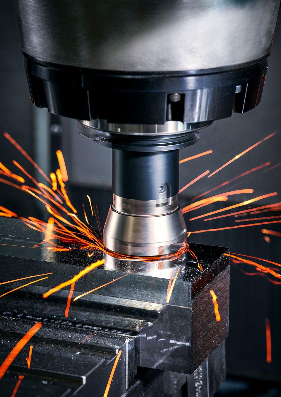
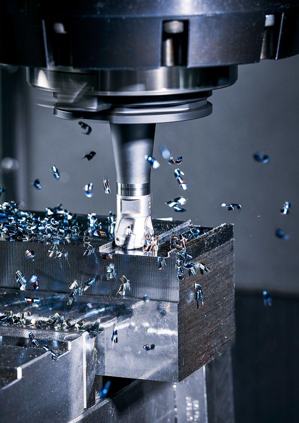
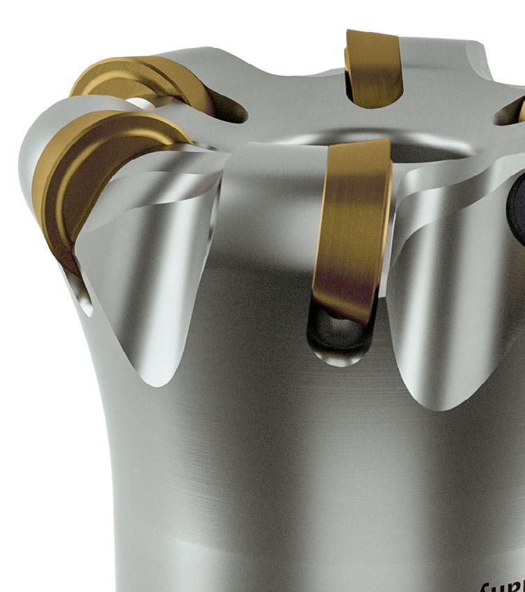
Milling cutter bodies
Well embedded: For a variety of cutting advantages.
In milling cutter body systems from POKOLM, precisely tailored tools and indexable inserts complement one another in a comprehensive product range that covers well over 90% of machining situations, in particular in tool and mold building.

The specially developed, patented insert seat provides optimal hold for cutting inserts in the tool arbor, facilitating high feed rates and longer tool lives through outstanding stability.
We offer specially designed tools with unique indexable insert geometries and an optimized smooth coating for machining non-ferrous metals and non-metals.
Tools with neutral or different positive adjustments offer optimal machining conditions for a wide range of different materials and machines.
The patented Pokolm DuoPlug® connection system eliminates looseness to the arbor and achieves high-precision surfaces in finishing, combined with high holding forces for requirements at extreme cuttingperformance in roughing.
State of the art technology: Almost all tools in the Pokolm tool system are equipped with an internal coolant supply.
2-point contact milling tools can be used with a plunging angle of 90°.
Safety in roughing. The shim acts both as protection and to dampen vibrations. This product feature also delivers process reliability and has a positive influence on smooth running performance.
Optimized geometries, carbide grades, specially developed for the properties of rust, acid, and heat resistant stainless steels, guarantee outstanding cutting results.
For more information on the special features of individual Pokolm tool systems, please see the following pages.
PRODUCT OVERVIEW 20 7 -x 0
Technology overview
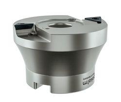
Milling cutter bodies
Improved economic efficiency
7 increments for round indexable inserts and numerous geometries and sizes – combined with many different axial angles in the cutter body – offer optimal conditions for almost any conceivable application.

Different axial angles for every requirement:
A negative basic shape delivers improved tooth stability and maximum smooth-running performance
A neutral geometry is outstanding for hard machining, and delivers maximum contour precision
Positive arbors, combined with cutting inserts with a hollow cavity, are highly suitable for less powerful machines and RSH materials
Tips and practical information Product overview Milling cutter bodies / indexable inserts Accessories Technical information Assembly instructions Order form Index 21
7 -x 0 7 -x 0 7 -x 0
Technology
overview
Milling cutter bodies
Optimal force distribution
The patented embedding of the indexable inserts in the carrier tool optimally dissipates the axial and radial cutting forces that occur, since the cutting insert is not held only by the Torx screw, but instead is supported in the carrier tool. This means the cutting pressure does not act solely on the cutting insert, but is also conducted into the milling body.
Compared to open insert seats, embedding the cutting insert also allows for stronger teeth, thereby significantly improving the stability of the tools. This makes it possible to achieve higher tool lives and feed rates. Additional double clamps also offer excellent hold under extreme conditions.
Reduced wear
Holding forces
Clamping
Cutting pressure
Support in the carrier body
Cutting pressure
Torx® screws
The chip rooms are specially designed to achieve easy machining processes and save material. Precisely matched coolant channels in the tools and arbors deliver the coolant directly to the cutting flute, even under difficult cutting conditions.
Specialized materials and special hard coatings offer higher tensile strength and thermal stability, and make Pokolm tools and arbor systems unbeatable in terms of durability and service life.
PRODUCT OVERVIEW 22
Additional (double) clamp
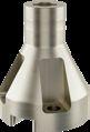
Indexable inserts
The complete product range
Pokolm’s product portfolio stands out for its broad diversity and well-designed range of indexable inserts.
Perfectly tailored to our tool system, with a large selection of grades, geometries, and different applications, they provide the optimal solution for any application:
Diameters from 5-20 mm, different shapes, materials, and coatings allow for any custom combination alongside a wide range of carrier tools and patented embedding.
All Pokolm indexable inserts are based on tested, practical applications from our customers, and are developed continuously in response to new challenges.
This ongoing and innovative development process, and intensive cooperation with our suppliers and coating partners, ensures we always supply state of the art quality.
Tips and practical information Product overview Milling cutter bodies / indexable inserts Accessories Technical information Assembly instructions Order form Index 23
Face mills

THINKING IN SOLUTIONS
PLANWORX® face mills
Properties
negative, and therefore extremely stable base form eight reliably usable cutting flutes easy cutting thanks to highly positive indexable insert geometry
uneven division for less vibration
coolant bore for media up to tool diameter 125 mm outstanding smooth-running design adjustment angle Kappa ~45°
Machining types
Highly economical with great machining depth and fantastic smooth-running design Practical video
Connection types

Cutting materials
Tips and practical information Product overview Milling cutter bodies / indexable inserts Accessories Technical information Assembly instructions Order form Index 25
Coating grade ISO application Application data (mm) Cutting flute length Thickness Radius P M K N S H f z a p l (mm) s (mm) r (mm) P40 PVSR – – – – – 0.08 - 0.55 0.1 - 6.0 13 5.4 0.8 K10 PVTi – – – – – 0.1 - 0.55 0.1 - 6.0 13 5.4 0.8 M40 PVST – – – – 0.08 - 0.3 0.1 - 4.0 13 5.4 0.8
1.0570 / 1015 / St 52 - 3 Sizes Page Ø 40 - 250 mm 26
PLANWORX® in
Ø 40 - 250 mm
Characteristics:
Application data (fz / ap)
*Tools do not have an internal coolant supply
26 PLANWORX ® FACE MILLS
PLANWORX®
Milling cutter bodies Part no. d1 I r l3 l2 d d2 d3 z Shell-type milling cutter body 4 40 331 40 13 0.8 42 6.7 53.5 22 40 4 5 50 331 50 13 0.8 52 6.7 63.5 27 48 5 6 63 331 63 13 0.8 52 6.7 76.5 27 60 6 8 80 331 80 13 0.8 52 6.7 93.5 32 70 8 10 100 331 100 13 0.8 52 6.7 113.5 40 90 10 12 125 331 125 13 0.8 52 6.7 138.5 40 90 12 14 160 331* 160 13 0.8 52 6.7 173.5 40 120 14 16 200 331* 200 13 0.8 52 6.7 213.5 60 160 16 20 250 331* 250 13 0.8 52 6.7 263.5 60 160 20 The accessories shown here must be used for all sizes! Accessories 40 505 P Torx screw > Page 197 15 500 P Torx wrench (Torx Plus) > Page 198 SG25 TORQUE CliX-S grip > Page 199 TG55 TORQUE CliX-T grip > Page 199 DM38 Torque adapter 3.8 Nm > Page199 TP15-R 6-pack bits (Torx Plus) > Page200 d d1 2 l 3 d3 d2 Indexable inserts Part no. DIN designation Quality Coating | s r M 05 31 842 SNMX 135408 ER P40 PVSR 13 5.4 0.8 M 4 05 31 862 SNMX 135408 ER K10 PVTi 13 5.4 0.8 M 4 05 31 8096 SNMX 135408 ER M40 PVST 13 5.4 0.8 M 4 S r l Material Coating grade Feed rate/ Depth of cut Steel Stainless steel Cast iron NF metal and non-metals High-temperature resistant alloys Hardened materials P40 PVSR f z (mm) a p (mm) 0.08-0.55 0.1-6 – – – – –K10 PVTi f z (mm) a p (mm) – –0.1-0.55 0.1-6 ––– –M40 PVST f z (mm) a p (mm) –0.08-0.3 0.1-4 – –0.08-0.2 0.1-3 –
Spindle speed (Vc in m/min)
Expanded application data
Tips and practical information Product overview Milling cutter bodies / indexable inserts Accessories Technical information Assembly instructions Order form Index 27 Material Coating grade Application Steel Stainless steel Cast iron NF metal and non-metals High-temperature resistant alloys Hardened materials P40 PVSR Roughing Semi-Finish Finish 100 200 300 100 200 300 –– – – –––K10 PVTi Roughing Semi-Finish Finish – –150 175 200 150 175 200 150 200 250 –– –– –M40 PVST Roughing Semi-Finish Finish –80 130 180 100 155 210 120 185 250 – –30 55 80 40 65 90 60 90 120 –
Full axial plunge Arbor Ø d1 X max mm 40-125 4 160-250 –Full oblique plunge Arbor Ø d1 α° y mm 40 <11 29.5 50 <8 39.5 63 <6.5 52.5 80 <4 69.5 100 <3.5 89.5 125 <2.5 114.5 160 <2 149.5 200 <1 189.5 250 <1 239.5 Circular milling Arbor Ø d1 Dmin mm D max mm 40 89.5 93.5 50 109.5 113.5 63 135.5 139.5 80 169.5 173.5 100 209.5 213.5 125 259.5 263.5 160 329.5 333.5 200 409.5 413.5 250 509.5 513.5 X d1 Y X α d1 D min max d1
MIRROWORX® Finishing face mills

MIRROWORX ® FACE MILLS
Finishing face mills
Mill instead of grind – smooth surfaces with outstanding affordability

Properties
surface qualities of Rz < 2.5 µm, completely eliminating the grinding process unique smooth-running design fine adjustment regulates axial run-out down to the µm also suitable for unstable components all three cutting flutes can be used reliably
Machining types
Connection types
Cutting materials
Tips and practical information Product overview Milling cutter bodies / indexable inserts Accessories Technical information Assembly instructions Order form Index 29
Coating grade ISO application Application data (mm) Cutting flute length Thickness Radius P M K N S H f z a p l (mm) s (mm) r (mm) S: HSC 05 PVTi HSC 05 PVTiH 0.1 - 1.5 0.02 - 0.2 8.2 3 0.5 M: HSC 05 PVTi 0.2 - 2.0 0.05 - 0.25 14.32 4 –MIRROWORX®
Practical video MIRROWORX® in 1.2312 Sizes Page S: Ø 16 - 35 mm 30 M: Ø 42 - 100 mm 32
® FACE MILLS

30
Indexable inserts Part no. DIN designation Quality Coating | s r M 03 83 835 TOHX 063005 ER HSC 05 PVTi 8.2 3 0.5 M 2.5 03 83 836 TOHX 063005 ER HSC 05 PVTiH 8.2 3 0.5 M 2.5 Milling cutter bodies Part no. d1 I r l3 l2 l1 d2 d3 z DuoPlug ® 1 16 283 SG 16 8.2 0.5 25 1 – M 10 15 1 2 20 283 SG 20 8.2 0.5 27 1 – M 12 18.6 2 2 25 283 SG 25 8.2 0.5 32 1 – M 16 23.5 2 Threaded shank end mill body 1 16 283 16 8.2 0.5 18 1 – M 8 13.8 1 2 20 283 20 8.2 0.5 18 1 – M 10 18 2 2 25 283 25 8.2 0.5 22.5 1 – M 12 21 2 2 30 283 30 8.2 0.5 28 1 – M 12 29 2 2 32 283 32 8.2 0.5 28 1 – M 16 29 2 2 35 283 35 8.2 0.5 28 1 – M 16 29 2 The accessories shown here must be used for all sizes! Accessories 25 500 Torx screw > Page 197 07 500 Torx wrench > Page 198 SG25 TORQUE CliX-S grip > Page 199 TG55 TORQUE CliX-T grip > Page 199 DM09 Torque adapter 0.9 Nm > Page 199 T07-R 6-pack bits (Torx) > Page 200 s r l 2 l d2 d1 3 d3 d1 l 2 l l 3 d3 d2 Characteristics:
MIRROWORX
MIRROWORX® Size S - Ø 16 - 35 mm
Application data (fz / ap)
Spindle speed (Vc in m/min)
Tips and practical information Product overview Milling cutter bodies / indexable inserts Accessories Technical information Assembly instructions Order form Index 31 Material Coating grade Feed rate/ Depth of cut Steel Stainless steel Cast iron NF metal and non-metals High-temperature resistant alloys Hardened materials HSC 05 PVTi f z (mm) a p (mm) 0.2-1 0.02-0.15 0.1-0.8 0.02-0.1 0.2-1 0.02-0.15 0.1-1.5 0.02-0.2 0.1-0.7 0.02-0.1 0.1-1 0.02-0.15 HSC 05 PVTiH f z (mm) a p (mm) 0.2-1 0.02-0.15 0.1-0.8 0.02-0.1 0.2-1 0.02-0.15 0.1-1.5 0.02-0.2 0.1-0.7 0.02-0.1 0.1-1 0.02-0.15
Material Coating grade Application Steel Stainless steel Cast iron NF metal and non-metals High-temperature resistant alloys Hardened materials HSC 05 PVTi Roughing Semi-Finish Finish ––150 275 400 ––100 150 200 ––200 275 350 ––100 450 800 ––40 70 100 –––100 175 250 HSC 05 PVTiH Roughing Semi-Finish Finish ––150 275 400 ––100 150 200 ––200 275 350 ––200 500 800 ––40 70 100 ––100 175 250
MIRROWORX ® FACE MILLS
Size M - Ø 42 - 100 mm
32
Milling cutter bodies Part no. d1 I r l3 l2 l1 d2 d3 z Shell-type milling cutter body 2 42 384 42 14.32 – 43 1 – 16 35 2 Accessories GWSTPS8ISK Setscrew with hexagon socket > Page 198 2 52 384 52 14.32 – 43 1 – 22 48 2 2 66 384 66 14.32 – 53 1 – 27 60 2 2 80 384 80 14.32 – 53 1 – 27 60 2 2 100 384 100 14.32 – 53 1 – 32 70 2 The accessories shown here must be used for all sizes! Accessories 35 500 L Torx screw > Page 197 45 500 L Torx screw > Page 197 15 500 Torx wrench > Page 198 20 500 Torx wrench > Page 198 SG25 TORQUE CliX-S grip > Page 199 TG55 TORQUE CliX-T grip > Page 199 DM25 Torque adapter 2.5 Nm > Page 199 T15-R 6-pack bits (Torx) > Page 200
MIRROWORX®
Indexable inserts Part no. DIN designation Quality Coating | s r M 04 84 835 TEHX 16T3 ZF HSC 05 PVTi 14.32 4 – M 3.5 04 84 835 EC TEHX 16T3 ZF HSC 05 PVTi 14.32 4 – M 3.5 d3 l 2 l l 3 d1 d2 s l s l Characteristics:
Application data (fz / ap)
Spindle speed (Vc in m/min)
Tips and practical information Product overview Milling cutter bodies / indexable inserts Accessories Technical information Assembly instructions Order form Index 33 Material Coating grade Feed rate/ Depth of cut Steel Stainless steel Cast iron NF metal and non-metals High-temperature resistant alloys Hardened materials HSC 05 PVTi f z (mm) a p (mm) 0.5-2 0.05-0.2 0.5-1 0.05-0.1 0.5-2 0.05-0.2 0.5-2 0.05-0.25 0.2-1 0.05-0.1 0.2-1 0.05-0.1
Material Coating grade Application Steel Stainless steel Cast iron NF metal and non-metals High-temperature resistant alloys Hardened materials HSC 05 PVTi Roughing Semi-Finish Finish –– 150 275 400 ––100 150 200 –– 200 275 350 –– 100 450 800 ––40 70 100 ––– 35 143 250
Sharp corner and slot milling cutters
THINKING IN SOLUTIONS
SLOTWORX® sharp corner and slot milling cutters

With state of the art cutting flute geometry for universal applications
Properties
universal applications: roughing and finishing steel, aluminum, graphite, plastic, hardened materials, cast iron and stainless as well as high-temperature resistant materials optimized coolant flow to the cutting flute integrated finishing chamfer achieves outstanding surface qualities
Bull ends of 0.4 - 5 mm
Machining types
Connection types
Cutting materials
Tips and practical information Product overview Milling cutter bodies / indexable inserts Accessories Technical information Assembly instructions Order form Index 35
Size ISO application Application data (mm) Cutting flute length Sizes, radii (mm), qualities P M K N S H f z a p l (mm) 0.4 0.8 1.0 2.0 3.0 4.0 5.0 HP-S 0.05 - 0.3 0.3 - 2.0 6.2 – HSC05 – – – – –M 0.05 - 0.35 0.1 - 9.0 10 K10 K10, HSC05, P40, M40, M35 K10, HSC05, P40, PKD, M40 K10, M40 K10, M40 K10, M40 –L – 0.08 - 0.5 0.1 - 14 15 – –K10, P40, M40 K10, M40 K10, M40 K10, M40 K10, M40
Practical video SLOTWORX® M / zero length DuoPlug SK50 / 1.2344 ESU 48 HRC / X40CrMoV
Sizes Page S: Ø 10 - 32 mm 36 M: Ø 16 - 52 mm 38 L: Ø 25 - 100 mm 42
SLOTWORX ® SHARP CORNER AND SLOT MILLING CUTTERS

SLOTWORX® K90°
SLOTWORX® - size S - Ø 10 - 32 mm
36
Milling cutter bodies Part no. d1 I r l3 l2 l1 d2 d3 z DuoPlug ® 3 12 266 SG 12 6.2 0.8 28 0.7 – M 7 10.8 3 4 16 266 SG 16 6.2 0.8 31 0.7 – M 10 15 4 5 20 266 SG 20 6.2 0.8 33 0.7 – M 12 18.6 5 5 25 266 SG 25 6.2 0.8 35 0.7 – M 16 23.5 5 Threaded shank end mill body 2 10 266 M6 10 6.2 0.8 22.5 0.7 – M 6 9.75 2 3 12 266 M6 12 6.2 0.8 22.5 0.7 – M 6 11.5 3 4 16 266 16 6.2 0.8 27.5 0.7 – M 8 13.8 4 5 20 266 20 6.2 0.8 27.5 0.7 – M 10 18 5 5 25 266 25 6.2 0.8 32 0.7 – M 12 21 5 7 32 266 32 6.2 0.8 32 0.7 – M 16 29 7 End mills 2 30 10 166 G 10 6.2 0.8 30 0.7 70 10 9.75 2 3 36 12 166 G 12 6.2 0.8 36 0.7 81 12 11.5 3 4 48 16 166 G 16 6.2 0.8 48 0.7 96 16 15.5 4 The accessories shown here must be used for all sizes! Accessories 21 500 P Torx screw > Page 197 06 500 P Torx wrench (Torx Plus) > Page 198 SG25 TORQUE CliX-S grip > Page 199 TG55 TORQUE CliX-T grip > Page 199 DM06 Torque adapter 0.6 Nm > Page 199 TP06-R 6-pack bits (Torx Plus) > Page 200
l 2 l 3 l d1 d3 r d2 l d3 d2 l 2 l 3 d1 r Characteristics: d1 l 3 l 2 1 d2 r
Application data (fz / ap)
Spindle speed (Vc in m/min)
Expanded application data
Tips and practical information Product overview Milling cutter bodies / indexable inserts Accessories Technical information Assembly instructions Order form Index 37 Indexable inserts Part no. DIN designation Quality Coating | s r M 02 66 835 R08 XCHT 062208 SR HSC 05 PVTi 6.2 2.2 0.8 M 2 02 66 835 R08 D XCHT 062208 SR HSC 05 PVDiaN 6.2 2.2 0.8 M 2 Material Coating grade Feed rate/ Depth of cut Steel Stainless steel Cast iron NF metal and non-metals High-temperature resistant alloys Hardened materials HSC 05 PVTi f z (mm) a p (mm) 0.05-0.3 0.3-2 0.05-0.25 0.3-2 0.05-0.3 0.3-2 –0.05-0.25 0.3-2 0.05-0.25 0.3-2 HSC 05 PVDiaN f z (mm) a p (mm) – – –0.05-0.3 0.3-2 – –
Material Coating grade Application Steel Stainless steel Cast iron NF metal and non-metals High-temperature resistant alloys Hardened materials HSC 05 PVTi Roughing Semi-Finish Finish ––150 275 400 ––100 150 200 ––200 275 350 –––––40 70 100 ––35 143 250 HSC 05 PVDiaN Roughing Semi-Finish Finish –––––––––––200 500 800 ––––––
Full axial plunge Arbor Ø d1 X max mm 10-32 0.7 Full oblique plunge Arbor Ø d1 α° y mm 10 <2.5 4 12 <2 6 16 <1.6 10 20 <1.2 14 25 <1 19 32 <1 26 Circular milling Arbor Ø d1 Dmin mm D max mm 10 13 20 12 17 24 16 25 32 20 33 39 25 43 49 32 57 63 s r d1 X Y d1 X D min max d1
SLOTWORX ® SHARP CORNER AND SLOT MILLING CUTTERS
SLOTWORX® K90° SLOTWORX®

38
Milling cutter bodies Part no. d1 I r l3 l2 l1 d2 d3 z DuoPlug ® 2 16 267 SG 16 10 0.8-2 38 2.5 – M 10 15 2 2 20 267 SG 20 10 0.4-2 40 2.5 – M 12 18.6 2 3 25 267 SG 25 10 0.4-2 43 2.5 – M 16 23.5 3 Accessories 25 505 KP Screw for Slotworx M Ø16;20;25 > Page 197 Threaded shank end mill body 2 16 267 16 10 0.4-2 29 2.5 – M 8 13.8 2 2 20 267 20 10 0.4-2 29 2.5 – M 10 18 2 3 20 267 20 10 0.4-2 29 2.5 – M 10 18 3 3 25 267 25 10 0.4-2 33 2.5 – M 12 21 3 4 25 267 25 10 0.4-2 33 2.5 – M 12 21 4 Accessories 25 505 KP Screw for Slotworx M Ø16;20;25 > Page 197 4 32 267 32 10 0.4-2 43 2.5 – M 16 29 4 5 32 267 32 10 0.4-2 43 2.5 – M 16 29 5 5 42 267 42 10 0.4-2 43 2.5 – M 16 29 5 Accessories 25 505 P Screw for Slotworx M Ø 32;42;52 > Page 197 End mills 2 32 16 167 G 16 10 0.4-2 32 2.5 165 16 – 2 3 40 20 167 G 20 10 0.4-2 40 2.5 165 20 – 3 3 50 25 167 G 25 10 0.4-2 50 2.5 225 25 – 3 4 50 25 167 G 25 10 0.4-2 50 2.5 225 25 – 4 Accessories 25 505 KP Screw for Slotworx M Ø16;20;25 > Page 197
size M -
52
1 / 2 l 2 l 3 l d1 d3 r d2 l d3 d2 l 2 l 3 d1 r d1 l 3 l 2 1 d2 r Characteristics:
-
Ø 16 -
mm
Tips and practical information Product overview Milling cutter bodies / indexable inserts Accessories Technical information Assembly instructions Order form Index 39 Milling cutter bodies Part no. d1 I r l3 l2 l1 d2 d3 z Shell-type milling cutter body 5 42 367 42 10 0.4-2 43 2.5 – 16 35 5 6 52 367 52 10 0.4-2 53 2.5 – 22 40 6 Accessories 25 505 P Screw for Slotworx M Ø 32;42;52 > Page 197 The accessories shown here must be used for all sizes! Accessories 08 500 P Torx wrench (Torx Plus) > Page 198 SG25 TORQUE CliX-S grip > Page 199 TG55 TORQUE CliX-T grip > Page 199 DM10 Torque adapter 1.0 Nm > Page 199 T10-R 6-pack bits (Torx) > Page 200 2 / 2 d1 l 2 3 l d3 r d2 Indexable inserts Part no. DIN designation Quality Coating | s r M 04 67 820 R04 XDHT 10T304 FR K10 Polished 10 3.58 0.4 M 2.5 04 67 820 R08 XDHT 10T308 FR K10 Polished 10 3.58 0.8 M 2.5 04 67 837 R08 XDMT 10T308 ER HSC 05 PVFN 10 3.58 0.8 M 2.5 04 67 848 R08 XDMT 10T308 ER P40 PVGO 10 3.58 0.8 M 2.5 04 67 896 R08 XDMT 10T308 ER M40 PVST 10 3.58 0.8 M 2.5 04 67 8099 R08 XDMT 10T308 ER M35 PCTC 10 3.58 0.8 M 2.5 04 67 820 XDHT 10T310 ER K10 Polished 10 3.58 1 M 2.5 04 67 837 XDMT 10T310 ER HSC 05 PVFN 10 3.58 1 M 2.5 04 67 844 XDHT 10T310 ER P40 PVGO 10 3.58 1 M 2.5 04 67 848 XDMT 10T310 ER P40 PVGO 10 3.58 1 M 2.5 04 67 860 XDHT 10T310 ER K10 PVTi 10 3.58 1 M 2.5 04 67 860 D XDHT 10T310 ER K10 PVDiaN 10 3.58 1 M 2.5 04 67 894 XDHT 10T310 ER PKD uncoated 10 3.58 1 M 2.5 04 67 896 XDMT 10T310 ER M40 PVST 10 3.58 1 M 2.5 04 67 820 R20 XDHT 10T320 FR K10 Polished 10 3.58 2 M 2.5 04 67 896 R20 XDMT 10T320 ER M40 PVST 10 3.58 2 M 2.5 04 67 820 R30 XDHT 10T330 FR K10 Polished 10 3.58 3 M 2.5 04 67 896 R30 XDMT 10T330 ER M40 PVST 10 3.58 3 M 2.5 04 67 820 R40 XDHT 10T340 FR K10 Polished 10 3.58 4 M 2.5 04 67 896 R40 XDMT 10T340 ER M40 PVST 10 3.58 4 M 2.5 s l r
Application data (fz / ap)
40
Material Coating grade Feed rate/ Depth of cut Steel Stainless steel Cast iron NF metal and non-metals High-temperature resistant alloys Hardened materials r=0.4 mm K10 Polished f z (mm) a p (mm) – – –0.08-0.35 0.1-9 – –r=0.8 mm K10 Polished f z (mm) a p (mm) – – –0.08-0.35 0.1-9 – –HSC 05 PVFN f z (mm) a p (mm) 0.05-0.25 0.1-5 –0.05-0.25 0.1-4 – –0.08-0.25 0.1-5 P40 PVGO f z (mm) a p (mm) 0.05-0.25 0.1-6 0.05-0.25 0.1-3 0.05-0.25 0.1-6 –0.05-0.25 0.1-3 –M40 PVST f z (mm) a p (mm) 0.05-0.25 0.1-6 0.08-0.35 0.1-9 – –0.08-0.25 0.1-9 –M35 PCTC f z (mm) a p (mm) –0.08-0.35 0.1-9 – –0.08-0.25 0.1-9 –r=1 mm K10 Polished f z (mm) a p (mm) – – –0.08-0.35 0.1-9 – –HSC 05 PVFN f z (mm) a p (mm) 0.05-0.25 0.1-5 –0.05-0.25 0.1-4 – –0.08-0.25 0.1-5 P40 PVGO f z (mm) a p (mm) 0.05-0.25 0.1-6 0.05-0.25 0.1-3 0.05-0.25 0.1-6 –0.05-0.25 0.1-3 –K10 PVTi f z (mm) a p (mm) – – –0.08-0.35 0.1-9 0.08-0.12 0.1-3 0.08-0.15 0.1-1 K10 PVDiaN f z (mm) a p (mm) – – –0.08-0.35 0.1-9 – –PKD uncoated f z (mm) a p (mm) – – –0.08-0.2 0.1-4 – –M40 PVST f z (mm) a p (mm) 0.05-0.25 0.1-6 0.08-0.35 0.1-9 – –0.08-0.25 0.1-9 –r=2 mm K10 Polished f z (mm) a p (mm) – – –0.08-0.35 0.1-9 – –M40 PVST f z (mm) a p (mm) –0.08-0.35 0.1-9 – –0.08-0.25 0.1-9 –r=3 mm K10 Polished f z (mm) a p (mm) – – –0.08-0.35 0.1-9 – –M40 PVST f z (mm) a p (mm) –0.08-0.35 0.1-9 – –0.08-0.25 0.1-9 –r=4 mm K10 Polished f z (mm) a p (mm) – – –0.08-0.35 0.1-9 – –M40 PVST f z (mm) a p (mm) –0.08-0.35 0.1-9 – –0.08-0.25 0.1-9 –
SLOTWORX ® SHARP CORNER AND SLOT MILLING CUTTERS
Spindle speed (Vc in m/min)
Expanded application data
Tips and practical information Product overview Milling cutter bodies / indexable inserts Accessories Technical information Assembly instructions Order form Index 41
Material Coating grade Application Steel Stainless steel Cast iron NF metal and non-metals High-temperature resistant alloys Hardened materials K10 Polished Roughing Semi-Finish Finish –––––––––100 450 800 100 450 800 100 450 800 ––40 70 100 –––HSC 05 PVFN Roughing Semi-Finish Finish 120 160 200 120 160 200 ––––100 150 200 100 150 200 –––––––80 150 220 40 130 220 40 130 220 P40 PVGO Roughing Semi-Finish Finish 100 150 200 100 150 200 160 205 250 90 110 130 90 110 130 110 135 160 110 130 150 110 130 150 120 150 180 –––60 80 100 60 80 100 80 100 120 –––M40 PVST Roughing Semi-Finish Finish 80 140 200 100 150 200 –80 130 180 100 155 210 120 185 250 ––––––30 55 80 40 65 90 60 90 120 –––M35 PCTC Roughing Semi-Finish Finish –––110 155 200 120 175 230 160 220 280 ––––––30 65 100 40 75 110 60 100 140 –––K10 PVTi Roughing Semi-Finish Finish –––––––––100 450 800 100 450 800 100 450 800 ––35 68 100 ––35 143 250 K10 PVDiaN Roughing Semi-Finish Finish –––––––––100 450 800 100 450 800 100 450 800 ––––––PKD uncoated Roughing Semi-Finish Finish –––––––––200 400 600 400 600 800 600 800 1000 ––––––
Full axial plunge Arbor Ø d1 X max mm 16-52 2.5 Full oblique plunge Arbor Ø d1 α° y mm 16 <24.5 5.3 20 <14.5 9.3 25 <8 14.3 32 <5 21.3 42 <3 31.3 52 <2.5 41.3 Circular milling Arbor Ø d1 Dmin mm D max mm 16 21.3 32 20 29.3 40 25 39.3 50 32 53.3 64 42 73.3 84 52 93.3 104 d1 X α d1 Y X D min max d1
SLOTWORX ® SHARP CORNER AND SLOT MILLING CUTTERS

SLOTWORX® K90°
SLOTWORX®
- size L - Ø 25 - 100 mm
42
Milling cutter bodies Part no. d1 I r l3 l2 l1 d2 d3 z Threaded shank end mill body 2 25 268 25 15 1-3 35 3 – M 12 21 2 3 32 268 32 15 1-3 43 3 – M 16 29 3 4 40 268 40 15 1-3 43 3 – M 16 29 4 4 42 268 42 15 1-3 43 3 – M 16 29 4 Shell-type milling cutter body 4 40 368 40 15 1-3 43 3 – 16 35 4 4 42 368 42 15 1-3 43 3 – 16 35 4 5 50 368 50 15 1-3 53 3 – 22 40 5 5 52 368 52 15 1-3 53 3 – 22 40 5 6 63 368 63 15 1-3 53 3 – 27 48 6 6 66 368 66 15 1-3 53 3 – 27 48 6 7 80 368 80 15 1-3 53 3 – 27 60 7 9 100 368 100 15 1-3 53 3 – 32 70 9 The accessories shown here must be used for all sizes! Accessories 35 500 Torx screw > Page 197 15 500 Torx wrench > Page 197 SG25 TORQUE CliX-S grip > Page 199 TG55 TORQUE CliX-T grip > Page 199 DM25 Torque adapter 2.5 Nm > Page 199 T15-R 6-pack bits (Torx) > Page 200
l d3 d2 l l d1 r d1 l 2 l 3 l d3 r d2 Characteristics:
Application data (fz / ap)
Spindle speed (Vc in m/min)
Tips and practical information Product overview Milling cutter bodies / indexable inserts Accessories Technical information Assembly instructions Order form Index 43 Indexable inserts Part no. DIN designation Quality Coating | s r M 05 68 820 XDHT 155210 FR K10 Polished 15 5.2 1 M 3.5 05 68 848 XDMT 155210 ER P40 PVGO 15 5.2 1 M 3.5 05 68 862 XDMT 155210 ER K10 PVTi 15 5.2 1 M 3.5 05 68 896 XDMT 155210 ER M40 PVST 15 5.2 1 M 3.5 05 68 820 R20 XDHT 155230 FR K10 Polished 15 5.2 2 M 3.5 05 68 896 R20 XDMT 155220 ER M40 PVST 15 5.2 2 M 3.5 05 68 820 R30 XDHT 155230 FR K10 Polished 15 5.2 3 M 3.5 05 68 896 R30 XDMT 155230 ER M40 PVST 15 5.2 3 M 3.5 05 68 820 R40 XDHT 155240 FR K10 Polished 15 5.2 4 M 3.5 05 68 896 R40 XDMT 155240 ER M40 PVST 15 5.2 4 M 3.5 05 68 820 R50 XDHT 155250 FR K10 Polished 15 5.2 5 M 3.5 05 68 896 R50 XDMT 155250 ER M40 PVST 15 5.2 5 M 3.5 s l r Material Coating grade Feed rate/ Depth of cut Steel Stainless steel Cast iron NF metal and non-metals High-temperature resistant alloys Hardened materials K10 Polished f z (mm) a p (mm) – – –0.08-0.35 0.1-14 – –P40 PVGO f z (mm) a p (mm) 0.1-0.5 0.2-14 –0.1-0.5 0.2-14 – – –K10 PVTi fz (mm) ap (mm) 0.1-0.4 4-14 –0.1-0.4 0.2-14 – – –M40 PVST f z (mm) a p (mm) –0.08-0.5 0.1-14 – –0.08-0.25 0.1-14 –
Material Coating grade Application Steel Stainless steel Cast iron NF metal and non-metals High-temperature resistant alloys Hardened materials K10 Polished Roughing Semi-Finish Finish – – –100 450 800 100 450 800 100 450 800 – –P40 PVGO Roughing Semi-Finish Finish 100 150 200 100 150 200 160 205 250 –110 130 150 110 130 150 120 150 180 – – –K10 PVTi Roughing Semi-Finish Finish 130 170 210 150 185 220 ––150 175 200 150 175 200 150 200 250 – – –M40 PVST Roughing Semi-Finish Finish –80 130 180 100 155 210 120 185 250 – –30 55 80 40 65 90 60 90 120 –
SLOTWORX ® SHARP CORNER AND SLOT MILLING CUTTERS
Expanded application data
44
Full axial plunge Arbor Ø d1 X max mm 25-100 3 Full oblique plunge Arbor Ø d1 α° y mm 25 <8.3 17 32 <5.9 24 40 <4.4 32 42 <4.2 34 50 <3.3 42 52 <3.2 44 63 <2.5 55 66 <2.4 58 80 <1.9 72 100 <1.5 92 Circular milling Arbor Ø d1 Dmin mm D max mm 25 42 50 32 56 64 40 72 80 42 76 84 50 92 100 52 96 104 63 118 126 66 124 132 80 152 160 100 192 200 D min max d1 d1 X α d1 Y X

Tips and practical information Product overview Milling cutter bodies / indexable inserts Accessories Technical information Assembly instructions Order form Index
QUADWORX®XL sharp corner and slot milling cutters

QUADWORX ® XL SHARP CORNER AND SLOT MILLING CUTTERS
QUADWORX®XL sharp corner and slot milling cutters

squaring the insert - excellent affordability for universal use
Properties
universal use as a sharp corner and slot milling cutter very high material removal rates and extremely easy cutting for more machine capacity 4 cutting flutes / cutting insert for highly economical use torsion eliminated by positioning the cutting inserts over a second flank and 90° contact maximum process reliability in interrupted cuts thanks to secure positioning of the inserts
cutter bodies with the designation RF are equally divided and have a hook of 5°
Machining types Connection types
Cutting materials
Tips and practical information Product overview Milling cutter bodies / indexable inserts Accessories Technical information Assembly instructions Order form Index 47 Size ISO application Application data (mm) Length (mm) Bull end (mm) Quality / coating P M K N S H f z a p | r XL – – 0.05 - 0.5 0.05 - 8 13 1 P40 PVGO P25 PVGO M40 PVST
Sizes Page XL: Ø 32 - 100 mm 48
QUADWORX ® XL SHARP CORNER AND SLOT MILLING CUTTERS
QUADWORX® XL - K90°
Size XL - Ø 32 - 100 mm
48
Milling cutter bodies Part no. d1 I r l3 l2 l1 d2 d3 z Threaded shank end mill body 2 32 251 32 13 1 42 1.5 – M 16 29 2 3 35 251 35 13 1 42 1.5 – M 16 29 3 Shell-type milling cutter body 4 40 351 40 13 1 42.5 2.5 – 16 35 4 4 42 351 42 13 1 42.5 2.5 – 16 35 4 Accessories GWSTPS8ISK Setscrew with hexagon socket > Page 198 4 50 351 50 13 1 50 2.5 – 22 40 4 5 50 351 50 13 1 50 2.5 – 22 40 5 5 50 351 RF 50 13 1 50 2.5 – 22 40 5 5 52 351 52 13 1 50 2.5 – 22 48 5 5 52 351 RF 52 13 1 50 2.5 – 22 48 5 6 63 351 63 13 1 53 2.5 – 27 48 6 6 63 351 RF 63 13 1 53 2.5 – 27 48 6 6 66 351 66 13 1 53 2.5 – 27 48 6 6 66 351 RF 66 13 1 53 2.5 – 27 48 6 6 80 351 80 13 1 53 2.5 – 27 60 6 8 80 351 80 13 1 53 2.5 – 27 60 8 7 100 351 100 13 1 53 2.5 – 32 70 7 9 100 351 100 13 1 53 2.5 – 32 70 9 Accessories 40 505 K Torx screw > Page 197 The accessories shown here must be used for all sizes! Accessories 15 500 P Torx wrench (Torx Plus) > Page 197 40 505 K Torx screw > Page 197 SG25 TORQUE CliX-S grip > Page 199 TG55 TORQUE CliX-T grip > Page 199 DM38 Torque adapter 3.8 Nm > Page 199 TP15-R 6-pack bits (Torx Plus) > Page 200
l 3 l 2 d1 d3 d2 r d1 l 2 l 3 d3 d2 l r Indexable inserts Part no. DIN designation Quality Coating | s r M 05 51 848 SDMT 135010 SN P40 PVGO 13 5 1 M 4 05 51 858 SDMT 135010 SN P25 PVGO 13 5 1 M 4 05 51 896 SDMT 135010 EN M40 PVST 13 5 1 M 4 S l r Characteristics:
Application data (fz / ap)
Speed (Vc in m/min)
Expanded application data
Tips and practical information Product overview Milling cutter bodies / indexable inserts Accessories Technical information Assembly instructions Order form Index 49 Material Coating grade Feed rate/ Depth of cut Steel Stainless steel Cast iron NF metal and non-metals High-temperature resistant alloys Hardened materials P40 PVGO f z (mm) a p (mm) 0.1-0.5 0.2-8 –0.1-0.5 0.2-8 – – –P25 PVGO f z (mm) a p (mm) 0.1-0.5 0.2-8 –0.1-0.5 0.2-8 – – –M40 PVST f z (mm) a p (mm) –0.05-0.3 0.1-6 – –0.05-0.25 0.05-6 –
Material Coating grade Application Steel Stainless steel Cast iron NF metal and non-metals High-temperature resistant alloys Hardened materials P40 PVGO Roughing Semi-Finish Finish 100 150 200 100 150 200 160 205 250 –110 130 150 110 130 150 120 150 180 – – –P25 PVGO Roughing Semi-Finish Finish 110 165 220 120 185 250 150 225 300 –120 145 170 130 150 170 135 193 250 – – –M40 PVST Roughing Semi-Finish Finish –80 130 180 100 155 210 120 185 250 – –30 55 80 40 65 90 60 90 120 –
Full axial plunge Arbor Ø d1 X max mm 32-35 1.5 40-100 2.5 Full oblique plunge Arbor Ø d1 α° y mm 32 <9 8.8 35 <7.0 11.8 40 <6.5 16.8 42 <5.8 18.8 50 <4.1 26.8 52 <3.7 28.8 63 <2.6 39.8 66 <2.4 42.8 80 <1.8 56.8 100 <1.2 72.8 Circular milling Arbor Ø d1 Dmin mm D max mm 32 40.8 62 35 46.8 68 40 56.8 78 42 60.8 82 50 76.8 98 52 80.8 102 63 102.8 124 66 108.8 130 80 136.8 158 100 176.8 198 d1 X d1 Y X α D min max d1
SLOTWORX® VF sharp corner and slot milling cutters

SLOTWORX ®
VF SHARP CORNER AND SLOT MILLING CUTTERS
SLOTWORX® VF

Finishing cutter
Ø 16 - 42 mm | Size M
Properties
finishing wall or floor surfaces large number of teeth for excellent feed rate available as threaded or DuoPlug® interface R 0.8 on the indexable insert reduces cutting pressure in addition, an indexable insert with R2 was developed newly designed cutter body with addition of R+ is suitable for use of both indexable inserts R0.8 and R2
Machining types
Connection types
Cutting materials
Tips and practical information Product overview Milling cutter bodies / indexable inserts Accessories Technical information Assembly instructions Order form Index 51
Sizes Page Ø 16 - 42 mm 52
Coating grade ISO application Application data (mm) Cutting flute length Thickness Radius P M K N S H f z a p l (mm) s (mm) r (mm) HSC 05 PPTi 0.05 - 0.3 0.5 - 2.8 9.52 2.38 0.8 HSC 05 PPTi 0.05 - 0.3 0.5 - 2.8 9.52 2.38 2.0
SLOTWORX ® VF SHARP CORNER AND SLOT MILLING CUTTERS

SLOTWORX® VF
16 - 42 mm | Size M
52
Milling cutter bodies Part no. d1 I r l3 l2 l1 d2 d3 z DuoPlug ® VF09-016-D10-02-R+ 16 3 0.8 35 – – M 10 15 2 VF09-020-D12-03-R+ 20 3 0.8 37.5 – – M 12 18.6 3 VF09-025-D16-04-R+ 25 3 0.8 42 – – M 16 23.5 4 Threaded shank end mill body VF09-016-E08-02-R+ 16 3 0.8 27.5 – – M 8 13.8 2 VF09-020-E10-03-R+ 20 3 0.8 27.5 – – M 10 18 3 VF09-025-E12-04-R+ 25 3 0.8 32.5 – – M 12 21 4 VF09-032-E16-05-R+ 32 3 0.8 32.5 – – M 16 29 5 VF09-035-E16-06-R+ 35 3 0.8 32.5 – – M 16 29 6 VF09-042-E16-07-R+ 42 3 0.8 32.5 – – M 16 29 7 The accessories shown here must be used for all sizes! Accessories 25 500 Torx screw > Page 197 07 500 Torx wrench > Page 198 SG25 TORQUE CliX-S grip > Page 199 TG55 TORQUE CliX-T grip > Page 199 DM09 Torque adapter 0.9 Nm > Page 199 T07-R 6-pack bits (Torx) > Page 200
Ø
Indexable inserts Part no. DIN designation Quality Coating | s r M VF09-8035-R08-LH-2 BPHX 090308 PER-1,5 HSC 05 PPTi 9.52 2.38 0.8 M 2.5 VF09-8035-R20-LH-2 BPHX 090320 PER HSC 05 PPTi 9.52 2.38 2.0 M 2.5 l r s Characteristics: d3 3 d2 d3 d2 3 d1 d1 r r l 3° 3° 3 d3 d2 3 d1 r r 3° 3° New
Application data (fz / ap)
Spindle speed (Vc in m/min)
Note: The indexable insert "VF09-8035-R20-LH-2" with radius R2 can only be used in cutter bodies with the addendum of R+! Indexable inserts with a radius R0.8 can also be used in cutter bodies with the addendum R+.
Tips and practical information Product overview Milling cutter bodies / indexable inserts Accessories Technical information Assembly instructions Order form Index 53 Material Coating grade Application Steel Stainless steel Cast iron NF metal and non-metals High-temperature resistant alloys Hardened materials HSC 05 PPTi Roughing Semi-Finish Finish ––135 225 450 ––110 165 220 ––160 225 290 ––200 500 800 ––60 110 160 ––120 180 250
Material Coating grade Feed rate/ Depth of cut Steel Stainless steel Cast iron NF metal and non-metals High-temperature resistant alloys Hardened materials HSC 05 PPTi f z (mm) a p (mm) 0.05-0.2 0.5-2.8 0.05-0.12 0.5-2 0.05-0.15 0.5-2.5 0.05-0.3 0.3-2 0.05-0.12 0.5-2 0.05-0.17 0.5-2.5
SQUAREWORX ® SHARP CORNER, SLOT AND CHAMFER MILLING WITH JUST ONE CUTTING INSERT

SQUAREWORX®
Sharp corner, slot and chamfer mills
SQUAREWORX®
One for two
Sharp corner, slot and chamfer milling with just one cutting insert and two carriers
Properties
Tool K=90°: precise sharp corner, slot and slab milling, embedded cutting inserts

Tool K=45°: forwards and backwards chamfering, as well as deburring to ap=5 mm
Low storage costs thanks to just one cutting insert for both tool geometries
4 usable cutting flutes per insert, low costs for each cutting flute
15° relief, bull end =0.8 mm
Large no. of teeth ensures high feed rates
For roughing, cutting and finishing
Inserts for almost any material: peripheral grinding, very sharp inserts for nonferrous materials; sintered inserts for all other materials
Machining types
Cutting materials
Connection types
Practical video
SQUAREWORX®
More product videos are available at: youtube.de/pokolmknowhow
Tips and practical information Product overview Milling cutter bodies / indexable inserts Accessories Technical information Assembly instructions Order form Index 55
Coating grade ISO application Application data (mm) Cutting flute length Thickness Radius P M K N S H f z a p l (mm) s (mm) r (mm) P40 PPGO – – 0.05 - 0.3 0.1 - 5 9 3.97 0.8 K10 PCSR – – – – 0.05 - 0.2 0.1 - 5 9 3.97 0.8 M35 PCTC – – – – 0.05 - 0.25 0.1 - 5 9 3.97 0.8 M40 PPST – – – 0.04 - 0.25 0.1 - 5 9 3.97 0.8 K10 Polished – – – – – 0.05 - 0.35 0.1 - 5 9 3.97 0.8
Sizes Page Diameter 25 - 66| K= 90° 57 Diameter 16 - 63| K= 45° 58
SQUAREWORX ® SHARP CORNER, SLOT AND CHAMFER MILLING WITH JUST ONE CUTTING INSERT
SQUAREWORX® in detail
One cutting insert for two carriers
Sharp corner and slot milling cutters
SQ09-...-90
4 cutting flutes, 0.8 mm corner radius
SQUAREWORX - order number key
Tool cutter body:
SQ09-025-Z25-03-50-90
Chamfer mill SQ09-...-45
Inserts
Tool type
SQ - SQUAREQOEX®
Insert size
l/d mm
Nominal diameter
Diameter mm [d1]
Type of connection
A - Threaded connection
E - Shell-type connection
Z - Plain shank
Connection size
Diameter mm [d1]
No. of teeth
Usable length
mm [l3]
Kappa °
SQ09-8042-R08-MP
Tool type
SQ - SQUAREWORX®
Insert size
l/d mm
Type description
Bull end
Chip groove
L - for light use
M - for moderate use
R - for heavy use
ISO material classification
P - Steel
M - Stainless steel
K - Cast iron
N - F metals and non-metals
S - High-temperature resistant alloys
H - Hardened materials
56
SQUAREWORX®
Size M | Sharp corner and slot milling cutters - K=90°

Tips and practical information Product overview Milling cutter bodies / indexable inserts Accessories Technical information Assembly instructions Order form Index 57
Threaded shank end mill body SQ09-025-E12-03-90 25 9 0.8 35 1 – M 12 21 3 SQ09-032-E16-04-90 32 9 0.8 40 1 – M 16 29 4 SQ09-035-E16-04-90 35 9 0.8 40 1 – M 16 29 4 SQ09-040-E16-05-90 40 9 0.8 40 1 – M 16 29 5 SQ09-042-E16-05-90 42 9 0.8 40 1 – M 16 29 5 Shell-type milling cutter body SQ09-040-A16-05-90 40 9 0.8 40 1 – 16 35 5 SQ09-042-A16-05-90 42 9 0.8 40 1 – 16 35 5 SQ09-050-A22-06-90 50 9 0.8 40 1 – 22 40 6 SQ09-052-A22-06-90 52 9 0.8 40 1 – 22 40 6 SQ09-063-A27-07-90 63 9 0.8 50 1 – 27 48 7 SQ09-066-A27-07-90 66 9 0.8 50 1 – 27 48 7 The accessories shown here must be used for all sizes! Accessories 30 505 P Torx screw > Page 197 08 500 P Torx wrench (Torx Plus) > Page 198 SG25 TORQUE CLiX S-grip > Page 199 TG55 TORQUE CLiX T-grip > Page 199 DM15 Torque adapter 1.5 Nm > Page 199 TP08-R 6-pack bits (Torx Plus) > Page 200 Milling Cutter Bodies Part no. d1 | r l3 l2 l1 d2 d3 z End mills SQ09-025-Z25-03-50-90 25 9 0.8 50 1 – 25 24 3 Characteristics: l 2 d2 l 1 l l 3 r d1 l l 2 d1 l 3 d3 d2 r l l 2 d1 l 3 d3 r d2
SQUAREWORX ® SHARP CORNER, SLOT AND CHAMFER MILLING WITH JUST ONE CUTTING INSERT

SQUAREWORX®
Size M | Chamfer mill - K=45°
58
shank end mill body SQ09-016-E10-03-45 16 9 0.8 25 1.2 – M 10 18 3 SQ09-020-E12-03-45 20 9 0.8 30 1.2 – M 12 21 3 SQ09-025-E12-04-45 25 9 0.8 30 1.2 – M 12 21 4 SQ09-035-E16-05-45 35 9 0.8 40 1.2 – M 16 29 5 Shell-type milling cutter body SQ09-040-A16-06-45 40 9 0.8 40 1.2 – 16 35 6 SQ09-050-A22-07-45 50 9 0.8 40 1.2 – 22 40 7 SQ09-063-A27-08-45 63 9 0.8 50 1.2 – 27 48 8 The accessories shown here must be used for all sizes! Accessories 30 505 P Torx screw > Page 197 08 500 P Torx wrench (Torx Plus) > Page 198 SG25 TORQUE CLiX S-grip > Page 199 TG55 TORQUE CLiX T-grip > Page 199 DM15 Torque adapter 1.5 Nm > Page 199 TP08-R 6-pack bits (Torx Plus) > Page 200
Threaded
Milling Cutter Bodies Part no. d1 | r l3 l2 l1 d2 d3 z End mills SQ09-016-Z16-03-32-45 16 9 0.8 32 1.2 – 16 13.8 3 SQ09-020-Z20-03-40-45 20 9 0.8 40 1.2 – 20 18 3 SQ09-025-Z25-04-50-45 25 9 0.8 50 1.2 – 25 21 4 Characteristics: d3 l 3 d1 l 1 d2 45° r d2 d3 l 3 d1 r 45° d1 3 d3 45° r d2
Application data (fz / ap)
Spindle speed (Vc in m/min)
Tips and practical information Product overview Milling cutter bodies / indexable inserts Accessories Technical information Assembly instructions Order form Index 59
Material Coating grade Feed rate/ Depth of cut Steel Stainless steel Cast iron NF metal and non-metals Hightemperature resistant alloys Hardened materials P40 PPGO fz (mm) 0.05 - 0.3 0.05- 0.17 0.05 - 0.2 – 0.04 - 0.13 –ap (mm) 0.1 - 5 0.1 - 5 0.1 - 5 – 0.1 - 4 –K10 PCSR fz (mm) 0.05 - 0.2 – 0.05 - 0.2 – – –ap (mm) 0.1 - 2.5 – 0.1 - 5 – – –M35 PCTC fz (mm) – 0.05 - 0.25 – – 0.05 - 0.25 –ap (mm) – 0.1 - 5 – – 0.1 - 5 –M40 PPST fz (mm) 0.05 - 0.25 0.04 - 0.25 – – 0.04 - 0.15 –ap (mm) 0.1 - 5 0.1 - 5 – – 0.1 - 5 –K10 Polished fz (mm) – – – 0.05 - 0.35 – –ap (mm) – – – 0.1 - 5 – –Indexable Inserts Part no. DIN designation Quality Coating | s r M SQ09-8048-R08-MP SDKT 09T308 SR P40 PPGO 9 3.97 0.8 M 3 SQ09-8062-R08-MK SDKT 09T308 SR K10 PCSR 9 3.97 0.8 M 3 SQ09-8099-R08-MS SDKT 09T308 SR M35 PCTC 9 3.97 0.8 M 3 SQ09-8096-R08-MM SDKT 09T308 SR M40 PPST 9 3.97 0.8 M 3 SQ09-8020-R08-MN SDHT 09T308 FR K10 Polished 9 3.97 0.8 M 3
Material Coating grade Application Steel Stainless steel Cast iron NF metal and non-metals Hightemperature resistant alloys Hardened materials P40 PPGO Roughing 100 150 200 90 110 130 110 130 150 60 80 100 – Semi-Finish 100 150 200 90 110 130 110 130 150 60 80 100 Finish – – – –K10 PCSR Roughing –– 140 180 220 – – – Semi-Finish 100 180 260 160 190 220 Finish – 160 190 220 M35 PCTC Roughing – 110 155 200 – – 30 65 100 – Semi-Finish 120 175 230 40 75 110 Finish 160 220 280 60 100 140 M40 PPST Roughing 80 140 200 80 130 180 – – 30 55 80 – Semi-Finish 100 150 200 1100 155 210 40 65 90 Finish – 120 185 250 60 90 120 K10 Polished Roughing – – – 100 450 800 – – Semi-Finish 100 450 800 Finish 100 450 800 s l r
SQUAREWORX ® SHARP CORNER, SLOT AND CHAMFER MILLING WITH JUST ONE CUTTING INSERT
Expanded application data
60
Full axial plunge Arbor Ø d1 X max mm 25 - 32 0.5 35 0.4 40 - 63 0.3 Full oblique plunge Arbor Ø d1 ° y mm 25 <2.00 12.2 32 <1.50 19.2 35 <1.00 22.2 40 <0.60 27.2 42 <0.55 29.2 50 <0.45 37.2 52 <0.40 39.2 63 <0.30 50.2 66 <0.30 53.2 Circular milling Arbor Ø d1 Dmin mm D max mm 25 37.2 48 32 51.2 62 35 57.2 68 40 67.2 78 42 71.2 82 50 87.2 98 52 91.2 102 63 113.2 124 66 119.2 130
d1 X α X Y d1 d1 D min max

Tips and practical information Product overview Milling cutter bodies / indexable inserts Accessories Technical information Assembly instructions Order form Index 61
Copy end mills

THINKING IN SOLUTIONS
SPINWORX® innovative copy end mill system

For lightly manned production with self-turning cutting inserts
Properties
100% use of the complete cutting flute minimized set-up times, no manual re-locating of the inserts is necessary much longer tool life and chip volume without stopping the production process optimally suited for roughing and remaining material machining reduced chip compression leads to lower power consumption, which also protects your machine spindle
Machining types
Connection types
Cutting materials
Tips and practical information Product overview Milling cutter bodies / indexable inserts Accessories Technical information Assembly instructions Order form Index 63
Size ISO application d (mm) Geometry / quality P M K N S H 0 1 3 4 6 7 r3.5 7 – – B C, E, F – B r5 10 – – B C, E, F – B r6 12 – – B C, E, F – B r8 16 – – B C, E, F – B r10 20 – – – C, E, F – B
Practical
SPINWORX®
1.2738
tool
40CrMnNiMo8-6-4
video
in
/
life 13 hours /
Sizes Page r 3.5 Ø 16 - 35 mm 65 r 5 Ø 20 - 52 mm 68 r 6 Ø 24 - 100 mm 72 r 8 Ø 32 - 125 mm 76 r 10 Ø 100 - 160 mm 80
SPINWORX® copy end mill

Optimized cutter body tool contour
The geometry of SPINWORX® tools facilitates optimal chip removal, in particular when machining pockets and grooves. In addition, the rounded outer contour effectively prevents chips sticking to the tool.
The cutter body base material is the decisive factor


Spinworx cutter body tools are made of a high-quality base material in order to ensure extremely long tool run times with one set of cutting inserts.
Insert seat
The large transition radius of the seats in SPINWORX® tools prevents an increased notching effect from the start. Another advantage is that the base of the tooth cannot break off due to overload.
The self-rotating insert

One key component of the SPINWORX® tool system are self-rotating inserts, which are optimally matched to the cutter bodies. Here as well, the special design features ensure the reliable long-term function of these components. Cutting materials with and without chip groove and different cutting flute geometries are available to handle a wide range of applications.
Pin/insert combination
The cylindrical contact surface of the insert has an exactly defined percentage of contact area. The cylindrical part of the pin secures the additional support in the cutter body tool.
Order number key
Tool cutter body: DR10-025-E12-03
Tool type
Insert size Ø mm [d]
Nominal diameter mm [d1]
Type of connection
E - Shell-type connection
A - Threaded connection
Connection size Ø mm [d2]
No. of teeth
The race
All SPINWORX® inserts are equipped with a race. This ensures constant rotation, and supports the characteristics of the embedded insert seat.
Inserts: DR 10 - 8 C 4
Tool type
Insert size [Ø mm] [d]
Identification feature
Quality | Suitability
Quality | Suitability
64 SPINWORX ® COPY END MILL
B M35 Stainless steel / high-temperature resistant alloys C K10 Steel / cast iron / hardened materials < 60 HRC E P25 Steel / cast iron F P40 Steel / cast iron 3 Ground with chip groove, 11° relief 4 Sintered without chip groove, 15° relief 7 Ground with chip groove, 15° relief
r3.5 - Ø 16 - 35 mm, 7° positive
7°

Tips and practical information Product overview Milling cutter bodies / indexable inserts Accessories Technical information Assembly instructions Order form Index 65 Milling cutter bodies Part no. d1 d r l3 l2 l1 d2 d3 z Threaded shank end mill body DR07-016-E08-02 16 7 3.5 28.5 1.2 – M 8 13.8 2 DR07-020-E10-05 20 7 3.5 28.5 1.2 – M 10 18 5 DR07-025-E12-06 25 7 3.5 28.5 1.2 – M 12 21 6 DR07-030-E12-07 30 7 3.5 28.5 1.2 – M 12 21 7 DR07-035-E16-08 35 7 3.5 28.5 1.2 – M 16 29 8 The accessories shown here must be used for all sizes! Accessories SG25 TORQUE CliX-S grip > Page 199 TG55 TORQUE CliX-T grip > Page 199 DM04 Torque adapter 0.4 Nm > Page 199 T06-R 6-pack bits (Torx) > Page 200 Z 00043 HTC ceramic paste WS 600 005 > Page 200 SPINWORX®
d2 d d1 d3 l 2 l 3
Characteristics:
Application data (fz / ap)
66 SPINWORX ® COPY END MILL Material Coating grade Feed rate/ Depth of cut Steel Stainless steel Cast iron NF metal and non-metals High-temperature resistant alloys Hardened materials B3 f z (mm) a p (mm) –0.1-0.5 0.1-0.75 – –0.1-0.4 0.1-1 –C4 f z (mm) a p (mm) 0.1-0.4 0.1-0.5 –0.1-0.3 0.1-0.7 – –0.1-0.15 0.1-0.2 E4 f z (mm) a p (mm) 0.1-0.4 0.1-0.5 –0.1-0.3 0.1-0.4 – – –F4 f z (mm) a p (mm) 0.1-0.5 0.1-0.8 –0.1-0.3 0.1-0.7 – – –B7 f z (mm) a p (mm) –0.1-0.5 0.1-0.75 – –0.1-0.4 0.1-1 –
Indexable inserts Part no. DIN designation Quality Coating d s r M DR07-8B3 RORM 0727 M0EN B3 – 7 2.7 3.5 –DR07-8C4 RDRA 0727 M0SN C4 – 7 2.7 3.5 –DR07-8E4 RDRA 0727 M0SN E4 – 7 2.7 3.5 –DR07-8F4 RDRA 0727 M0SN F4 – 7 2.7 3.5 –DR07-8B7 RDRM 0727 M0EN B7 – 7 2.7 3.5 –s d 15° s d 11° s d 15°
Spindle speed (Vc in m/min)
Expanded application data
Tips and practical information Product overview Milling cutter bodies / indexable inserts Accessories Technical information Assembly instructions Order form Index 67 Material Coating grade Application Steel Stainless steel Cast iron NF metal and non-metals High-temperature resistant alloys Hardened materials B3 Roughing Semi-Finish Finish –110 155 200 120 175 230 –– –30 65 100 40 75 110 ––C4 Roughing Semi-Finish Finish 90 150 210 110 165 220 ––150 195 240 140 205 270 –– ––35 108 180 –E4 Roughing Semi-Finish Finish 100 175 250 100 200 300 –––130 165 200 –– – –F4 Roughing Semi-Finish Finish 100 175 250 100 200 300 ––110 130 150 140 180 220 –– – –B7 Roughing Semi-Finish Finish –110 155 200 120 175 230 –– –30 65 100 40 75 110 ––
Full axial plunge Arbor Ø d1 X max mm 16-35 1.2 Full oblique plunge Arbor Ø d1 α° y mm 16 <16.0 4 20 <8.5 8 25 <5.0 13 30 <3.5 18 35 <3.0 23 Circular milling Arbor Ø d1 Dmin mm D max mm 16 20 30 20 28 38 25 38 48 30 48 58 35 58 68 d1 X d1 X Y α Dmax d1 d1 X d1 X Y α Dmax d1 d1 X d1 X Y α Dmax d1
r5 - Ø 20 - 52 mm, 7° positive

68 SPINWORX ® COPY END MILL Milling cutter bodies Part no. d1 d r l3 l2 l1 d2 d3 z Threaded shank end mill body DR10-020-E10-02 20 10 5 29 2.5 – M 10 18 2 DR10-025-E12-03 25 10 5 32.5 1.5 – M 12 21 3 DR10-025-E12-04 25 10 5 32.5 1.5 – M 12 21 4 DR10-030-E12-04 30 10 5 33 2.5 – M 12 21 4 DR10-030-E16-04 30 10 5 43 2.5 – M 16 29 4 DR10-032-E16-04 32 10 5 43 2.5 – M 16 29 4 DR10-032-E16-05 32 10 5 43 2.5 – M 16 29 5 DR10-035-E16-05 35 10 5 43 2.5 – M 16 29 5 DR10-035-E16-06 35 10 5 43 2.5 – M 16 29 5 DR10-042-E16-06 42 10 5 43 2.5 – M 16 29 6 Shell-type milling cutter body DR10-040-A16-05 40 10 5 43 2.5 – 16 35 5 DR10-042-A16-05 42 10 5 43 2.5 – 16 35 5 DR10-042-A16-06 42 10 5 43 2.5 – 16 35 6 DR10-050-A22-07 50 10 5 52 2.5 – 22 40 7 DR10-052-A22-07 52 10 5 52 2.5 – 22 40 7 DR10-052-A22-08 52 10 5 52 2.5 – 22 40 8 The accessories
sizes! Accessories SG25 TORQUE CliX-S grip > Page 199 TG55 TORQUE CliX-T grip > Page 199 DM10 Torque adapter 1.0 Nm > Page 199 T10-R 6-pack bits (Torx) > Page 200 Z 00043 HTC ceramic paste WS 600 005 > Page 200
shown here must be used for all
SPINWORX®
d2 d d1 d3 l 2 l 3 3 d3 l 2 d1 d d2 7° Characteristics:
Application data (fz / ap)
Tips and practical information Product overview Milling cutter bodies / indexable inserts Accessories Technical information Assembly instructions Order form Index 69 Indexable inserts Part no. DIN designation Quality Coating | s r M DR10-8B3 RORM 1035 M0EN B3 – 10 3.5 5 –DR10-8C4 RDRA 1035 M0SN C4 – 10 3.5 5 –DR10-8E4 RDRA 1035 M0SN E4 – 10 3.5 5 –DR10-8F4 RDRA 1035 M0SN F4 – 10 3.5 5 –DR10-8B7 RDRM 1035 M0EN B7 – 10 3.5 5 –DR10-80B7 RDRM 1035 M0EN B7 – 10 3.5 5 –
Material Coating grade Feed rate/ Depth of cut Steel Stainless steel Cast iron NF metal and non-metals High-temperature resistant alloys Hardened materials B3 f z (mm) a p (mm) –0.15-0.6 0.2-2 – –0.1-0.4 0.15-2 –C4 f z (mm) a p (mm) 0.1-0.45 0.2-1 –0.15-0.35 0.1-1 – –0.1-0.15 0.1-0.3 E4 f z (mm) a p (mm) 0.1-0.45 0.2-1 –0.15-0.25 0.1-0.55 – – –F4 f z (mm) a p (mm) 0.1-0.5 0.2-1.5 –0.15-0.35 0.1-1 – – –B7 f z (mm) a p (mm) –0.15-0.6 0.2-2 – –0.1-0.4 0.15-2 –s d 15° s d 11° s d 15°
Spindle speed (Vc in m/min)
Expanded application data
70 SPINWORX ® COPY END MILL Material Coating grade Application Steel Stainless steel Cast iron NF metal and non-metals High-temperature resistant alloys Hardened materials B3 Roughing Semi-Finish Finish –110 155 200 120 175 230 –– –30 65 100 40 75 110–C4 Roughing Semi-Finish Finish 90 150 210 110 165 220 ––150 195 240 140 205 270– ––35 108 180 –E4 Roughing Semi-Finish Finish 100 175 250 100 200 300 –––130 165 200 –– – –F4 Roughing Semi-Finish Finish 100 175 250 100 200 300 ––110 130 150 140 180 220 –– – –B7 Roughing Semi-Finish Finish –110 155 200 120 175 230 –– –30 65 100 40 75 110 ––
Full axial plunge Arbor Ø d1 X max mm 20-52 2.5 Full oblique plunge Arbor Ø d1 α° y mm 20 <17.0 2 25 <19.5 7 30 <11.5 12 32 <10.0 14 35 <8.0 17 40 <6.0 22 42 <5.5 24 52 <4.0 34 Circular milling Arbor Ø d1 Dmin mm D max mm 20 22 38 25 32 48 30 42 58 32 46 62 35 52 68 40 62 78 42 66 82 52 86 102 d1 X d1 X Y α Dmax d1 d1 X d1 X Y α Dmax d1 d1 X d1 X Y α Dmax d1

Tips and practical information Product overview Milling cutter bodies / indexable inserts Accessories Technical information Assembly instructions Order form Index
r6 - Ø 24 - 100 mm, 7° positive

72 SPINWORX ® COPY END MILL Milling cutter bodies Part no. d1 d r l3 l2 l1 d2 d3 z Threaded shank end mill body DR12-024-E12-02 24 12 6 33 2.8 – M 12 21 2 DR12-032-E16-04 32 12 6 42.5 2.8 – M 16 29 4 DR12-035-E16-03 35 12 6 42.5 2.8 – M 16 29 3 DR12-035-E16-04 35 12 6 42.5 2.8 – M 16 29 4 DR12-035-E16-05 35 12 6 42.5 2.8 – M 16 29 5 Shell-type milling cutter body DR12-040-A16-05 40 12 6 42.5 2.8 – 16 35 5 DR12-040-A16-06 40 12 6 42.5 2.8 – 16 35 6 DR12-042-A16-05 42 12 6 42.5 2.8 – 16 35 5 Accessories GWSTPS8ISK Setscrew with hexagon socket > Page 198 DR12-050-A22-06 50 12 6 52.5 2.8 – 22 40 6 DR12-050-A22-07 50 12 6 52.5 2.8 – 22 40 7 DR12-052-A22-06 52 12 6 52.5 2.8 – 22 40 6 DR12-052-A22-07 52 12 6 52.5 2.8 – 22 40 7 DR12-063-A27-06 63 12 6 52.5 2.8 – 27 48 6 DR12-066-A27-07 66 12 6 52.5 2.8 – 27 48 7 DR12-066-A27-08 66 12 6 52.5 2.8 – 27 48 8 DR12-066-A27-09 66 12 6 52.5 2.8 – 27 48 9 DR12-080-A27-08 80 12 6 52.5 2.8 – 27 60 8 DR12-080-A27-09 80 12 6 52.5 2.8 – 27 60 9 DR12-080-A27-10 80 12 6 52.5 2.8 – 27 48 10 DR12-100-A32-10 100 12 6 63 2.8 – 32 70 10
used
sizes! Accessories SG25 TORQUE CliX-S grip > Page 199 TG55 TORQUE CliX-T grip > Page 199 DM10 Torque adapter 1.0 Nm > Page 199 T10-R 6-pack bits (Torx) > Page 200 Z 00043 HTC ceramic paste WS 600 005 > Page 200
The accessories shown here must be
for all
SPINWORX®
d2 d d1 d3 2 l 3 3 d3 l 2 d1 d d2 7° Characteristics:
Application data (fz / ap)
Tips and practical information Product overview Milling cutter bodies / indexable inserts Accessories Technical information Assembly instructions Order form Index 73 Indexable inserts Part no. DIN designation Quality Coating | s r M DR12-8B3 RORM 1245 M0EN B3 – 12 4.5 6 –DR12-8C4 RDRA 1245 M0SN C4 – 12 4.5 6 –DR12-8E4 RDRA 1245 M0SN E4 – 12 4.5 6 –DR12-8F4 RDRA 1245 M0SN F4 – 12 4.5 6 –DR12-8B7 RDRM 1245 M0EN B7 – 12 4.5 6 –DR12-80B7 RDRM 1245 M0SN B7 – 12 4.5 6 –
Material Coating grade Feed rate/ Depth of cut Steel Stainless steel Cast iron NF metal and non-metals High-temperature resistant alloys Hardened materials B3 f z (mm) a p (mm) –0.2-0.65 0.3-2.5 – –0.1-0.5 0.2-2.5 –C4 f z (mm) a p (mm) 0.1-0.5 0.2-1.5 –0.15-0.4 0.1-1.5 – –0.1-0.18 0.1-0.4 E4 f z (mm) a p (mm) 0.1-0.5 0.2-1.5 –0.15-0.3 0.1-0.8 – – –F4 f z (mm) a p (mm) 0.1-0.6 0.2-2 –0.15-0.4 0.1-1.5 – – –B7 f z (mm) a p (mm) –0.2-0.65 0.3-2.5 – –0.1-0.5 0.2-2.5 –80B7 f z (mm) a p (mm) –0.2-0.65 0.3-2.5 – –0.1-0.5 0.2-2.5 –s d 15° s d 11° s d 15°
Spindle speed (Vc in m/min)
Expanded application data
74 SPINWORX ® COPY END MILL Material Coating grade Application Steel Stainless steel Cast iron NF metal and non-metals High-temperature resistant alloys Hardened materials B3 Roughing Semi-Finish Finish –110 155 200 120 175 230 –– –30 65 100 40 75 110 ––C4 Roughing Semi-Finish Finish 150 180 210 110 165 220 ––150 195 240 140 205 270 –– ––35 108 180 –E4 Roughing Semi-Finish Finish 100 175 250 100 200 300 –––130 165 200 –– – –F4 Roughing Semi-Finish Finish 100 175 250 100 200 300 ––110 130 150 140 180 220 –– – –B7 Roughing Semi-Finish Finish –110 155 200 120 175 230 –– –30 65 100 40 75 110 ––80B7 Roughing Semi-Finish Finish –110 155 200 120 175 230 –– –30 65 100 40 75 110 ––
Full axial plunge Arbor Ø d1 X max mm 24-100 2.8 Full oblique plunge Arbor Ø d1 α° y mm 24 <19 2 32 <15.5 10 35 <12.0 13 40 <8.5 18 42 <7.5 20 50 <5.5 28 52 <5.0 30 63 <3.5 41 66 <3.5 44 80 <2 58 100 <2 78 Circular milling Arbor Ø d1 Dmin mm D max mm 24 26 46 32 42 62 35 48 68 40 58 78 42 62 82 50 78 98 52 82 102 63 104 124 66 110 130 80 138 158 100 178 198 d1 X d1 X Y α Dmax d1 d1 X d1 X Y α Dmax d1 d1 X d1 X Y α Dmax d1

Tips and practical information Product overview Milling cutter bodies / indexable inserts Accessories Technical information Assembly instructions Order form Index 75
SPINWORX®
r8 - Ø 32 - 125 mm, 7° positive

76 SPINWORX ® COPY END MILL Milling cutter bodies Part no. d1 d r l3 l2 l1 d2 d3 z Threaded shank end mill body DR16-032-E16-02 32 16 8 43.5 3.8 – M 16 29 2 DR16-040-E16-04 40 16 8 43.5 2.5 – M 16 29 4 Shell-type milling cutter body DR16-052-A22-05 52 16 8 53 2.5 – 22 40 5 DR16-052-A22-06 52 16 8 53 2.5 – 22 40 6 Accessories GWSTPS10ISK Setscrew with hexagon socket > Page 198 DR16-063-A27-06 63 16 8 53 2.5 – 27 48 6 DR16-066-A27-06 66 16 8 53 2.5 – 27 48 6 DR16-080-A27-07 80 16 8 53 2.5 – 27 60 7 DR16-100-A32-08 100 16 8 53 2.5 – 32 70 8 DR16-125-A40-09 125 16 8 53 2.5 – 40 90 9 Accessories M16X35 Cheese-head screw hexagon socket low head > Page 197 The accessories shown here must be used for all sizes! Accessories SG25 TORQUE CliX-S grip > Page 199 TG55 TORQUE CliX-T grip > Page 199 DM22 Torque adapter 2.2 Nm > Page 199 T20-R 6-pack bits (Torx) > Page 200 Z 00043 HTC ceramic paste WS 600 005 > Page 200
d2 d d1 d3 l 2 l 3 l 3 d3 l 2 d1 d d2 7° Characteristics:
Application data (fz / ap)
Tips and practical information Product overview Milling cutter bodies / indexable inserts Accessories Technical information Assembly instructions Order form Index 77 Indexable inserts Part no. DIN designation Quality Coating | s r M DR16-8B3 RORM 1655 M0EN B3 – 16 5.5 8 –DR16-8C4 RDRA 1655 M0SN C4 – 16 5.5 8 –DR16-8E4 RDRA 1655 M0SN E4 – 16 5.5 8 –DR16-8F4 RDRA 1655 M0SN F4 – 16 5.5 8 DR16-8B7 RDRM 1655 M0EN B7 – 16 5.5 8 –
Material Coating grade Feed rate/ Depth of cut Steel Stainless steel Cast iron NF metal and non-metals High-temperature resistant alloys Hardened materials B3 f z (mm) a p (mm) –0.2-0.7 0.5-3 – –0.15-0.5 0.2-3 –C4 f z (mm) a p (mm) 0.2-0.7 0.2-2.5 –0.2-0.5 0.2-3 – –0.15-0.22 0.2-0.55 E4 f z (mm) a p (mm) 0.2-0.7 0.2-2.5 –0.2-0.35 0.2-1.6 – –F4 f z (mm) a p (mm) 0.2-0.8 0.2-3 –0.2-0.5 0.2-3 – – –B7 f z (mm) a p (mm) –0.2-0.7 0.5-3 – –0.15-0.5 0.2-3 –s d 15° s d 11° s d 15°
Spindle speed (Vc in m/min)
Expanded application data
78 SPINWORX ® COPY END MILL Material Coating grade Application Steel Stainless steel Cast iron NF metal and non-metals High-temperature resistant alloys Hardened materials B3 Roughing Semi-Finish Finish –110 155 200 120 175 230 –– –30 65 100 40 75 110 ––C4 Roughing Semi-Finish Finish 90 150 210 110 165 220 ––150 195 240 140 205 270 –– ––35 108 180 –E4 Roughing Semi-Finish Finish 100 175 250 100 200 300 –––130 165 200 –– – –F4 Roughing Semi-Finish Finish 100 175 250 100 200 300 ––110 130 150 140 180 220 –– – –B7 Roughing Semi-Finish Finish –110 155 200 120 175 230 –– –30 65 100 40 75 110 ––
Full axial plunge Arbor Ø d1 X max mm 32-125 2.5 Full oblique plunge Arbor Ø d1 α° y mm 32 <20 2 40 <14.0 10 52 <6.0 22 63 <4.0 33 66 <3.5 36 80 <2.5 50 100 <2.0 70 125 <1.5 95 Circular milling Arbor Ø d1 Dmin mm D max mm 32 34 62 40 50 78 52 74 102 63 96 124 66 102 130 80 130 158 100 170 198 125 220 248
d1 X d1 X Y α Dmax d1 d1 X d1 X Y α Dmax d1 d1 X d1 X Y α Dmax d1
Tips and practical information Product overview Milling cutter bodies / indexable inserts Accessories Technical information Assembly instructions Order form Index
SPINWORX®
r10 - Ø 100 - 160 mm, 7° positive
Application data (fz / ap)
80 SPINWORX ® COPY END MILL Milling cutter bodies Part no. d1 d r l3 l2 l1 d2 d3 z Shell-type milling cutter body DR20-100-A32-07-L 100 20 10 53 4 – 32 70 7 DR20-125-A40-08-L 125 20 10 53 4 – 40 90 8 Accessories GWSTPS10ISK Setscrew with hexagon socket > Page 198 SG25 TORQUE CliX-S grip > Page199 TG55 TORQUE CliX-T grip > Page 199 DM22 Torque adapter 2.2 Nm > Page 199 T20-R 6-pack bits (Torx) > Page 200 Z 00043 HTC ceramic paste WS 600 005 > Page 200 DR20-160-A40-10-L 160 20 10 63 4 – 40 120 10 Accessories SG25 TORQUE CliX-S grip > Page 199 TG55 TORQUE CliX-T grip > Page 199 DM22 Torque adapter 2.2 Nm > Page 199 T20-R 6-pack bits (Torx) > Page 200 Z 00043 HTC ceramic paste WS 600 005 > Page 200
l 3 d3 l 2 d1 d d2 Indexable inserts Part no. DIN designation Quality Coating | s r M DR20-8C4-L RDRA 2065 M0SN C4 – 20 6.5 10 –DR20-8E4-L RDRA 2065 M0SN E4 – 20 6.5 10 –DR20-8F4-L RDRA 2065 M0SN F4 – 20 6.5 10 –
Material Coating grade Feed rate/ Depth of cut Steel Stainless steel Cast iron NF metal and non-metals High-temperature resistant alloys Hardened materials C4 f z (mm) a p (mm) 0.2-0.7 0.2-2.5 –0.2-0.5 0.2-3 – –0.15-0.23 0.2-0.55 E4 f z (mm) a p (mm) 0.2-0.7 0.2-2.5 –0.2-0.35 0.2-1.6 – –F4 f z (mm) a p (mm) 0.2-0.8 0.2-3 –0.2-0.5 0.2-3 – – –s d 15° 7° Characteristics:
Spindle speed (Vc in m/min)
Expanded application data
Tips and practical information Product overview Milling cutter bodies / indexable inserts Accessories Technical information Assembly instructions Order form Index 81 Material Coating grade Application Steel Stainless steel Cast iron NF metal and non-metals High-temperature resistant alloys Hardened materials C4 Roughing Semi-Finish Finish 90 150 210 110 165 220 ––150 195 240 140 205 270 –– ––35 108 180 –E4 Roughing Semi-Finish Finish 100 175 250 100 200 300 –––130 165 200 –– – –F4 Roughing Semi-Finish Finish 100 175 250 100 200 300 ––110 130 150 140 180 220 –– – –
Full axial plunge Arbor Ø d1 X max mm 100 2.0 125-160 3.0 d1 X d1 X Y α Dmax d1 Full oblique plunge Arbor Ø d1 α° y mm 100 <4.6 62 125 <3.3 87 160 <2.3 122 d1 X d1 X Y α Dmax d1 Circular milling Arbor Ø d1 Dmin mm D max mm 100 162 200 125 212 250 160 282 320 d1 X d1 X Y α Dmax d1
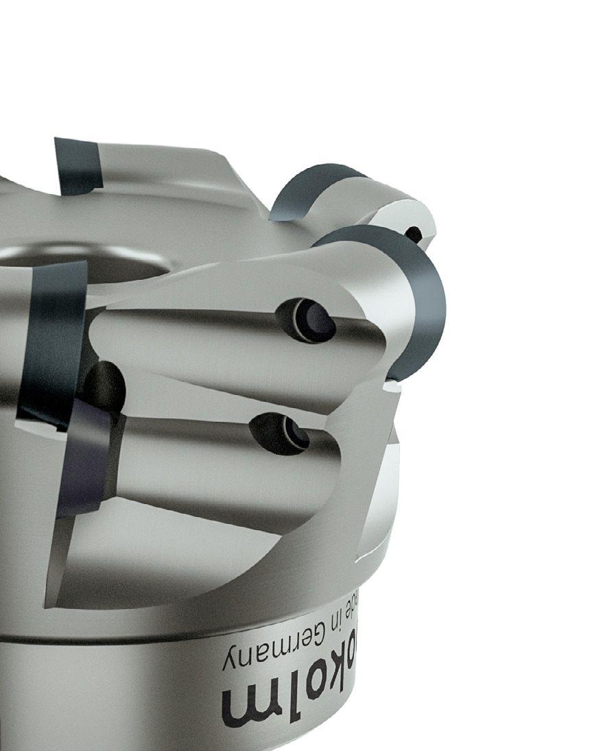
ROUND INSERT CUTTERS – COPY END MILLS
insert cutters K0-90°
Round
Round insert cutters K0-90°
Copy end mills
The universal choice for any job, from the regular to the unusual
Properties
Tool diameter 8 - 160 mm
0° axial angle for the most precise contours in combination with DuoPlug® maximum stability
7° axial angle ensures low power consumption stable tool cutter body thanks to indexable insert embedding

8 different cemented carbide qualities with 9 adapted high-performance coatings
Cutter bodies with the addendum VD have special vibration-damping properties
Machining types Connection types
Cutting materials
Tips and practical information Product overview Milling cutter bodies / indexable inserts Accessories Technical information Assembly instructions Order form Index 83
Quality | coating ISO application P M K N S H 7 - 1.99 7 - 2.38 10 12 16 20 HSC05 | PVTi; HSC05 | PVFN – • • • • • • K10 | PVTi – • • • • • • K10 | PVTi (RDHX with concave molding) – – – • • • • • –P25 | PVTi – – – – – • • • • • P25 | PVGO – – – – – • • • • –P25 | PVSR – – – – – • • • –P40 | PVTi – – – – – • • • • • • P40 | PVGO – – – – - • • • • –P40 | PVSR – – – • • • • • –P40 | PVML – – – – • • • • –CBN C – – – – – – – • – – –CBN S – – – – – – • • – – –K10 | Polished – – – – – • • • • • • K10 | PVDiaN – – – – – • • • • – –M40 | PVST – – – – – • • – –HSC03 | PPGH – – – • • • – –M35 | PCTC – – – – – • • • • –
Practical video ROUND INSERT 02 10 896 IN 1.4301 / 304 / X5CRNI18-10
Sizes Page r 3.5 - Ø 12 - 25 mm, s 1.99 84 r 3.5 - Ø 15 - 42 mm, s 238 86 r 5 - Ø 20 - 42 mm, neutral 91 r 5 - Ø 25 - 52 mm, 7° positive 96 r 5 - Ø 20 - 35 mm, CBN, neutral 101 r 6 - Ø 42 - 80 mm, 7° positive, shim 103 r 6 - Ø 24 - 80 mm, neutral, 7° positive 107 r 8 - Ø 52 - 100 mm, 7° positive, shim 112 r 8 - Ø 32 - 160 mm, neutral 7° positive 115 r 10 - Ø 40 - 160 mm, neutral 7° positive 119
ROUND INSERT CUTTERS – COPY END MILLS

Round insert cutters K0-90°
r3.5 - Ø 12 - 25 mm, s 1.99 mm
84
Milling cutter bodies Part no. d1 d r l3 l2 l1 d2 d3 z DuoPlug® 2 12 235 SG 12 7 3.5 24.5 – – M 7 10.8 2 Accessories 25 500 K-1 Torx screw > Page 197 3 15 235 SG 15 7 3.5 28 1.5 – M 10 14 3 5 25 235 SG 25 7 3.5 30 1.5 – M 16 23.5 5 Accessories 25 500 Torx screw > Page 197 Threaded shank end mill body 12 200 M6 12 7 3.5 28.5 – – M 6 11.5 2 12 200 12 7 3.5 28.5 – – M 8 11.8 2 Accessories 25 500 K-1 Torx screw > Page 197 3 15 235 15 7 3.5 28.5 1.5 – M 8 13.8 3 4 20 235 20 7 3.5 28.5 1.5 – M 10 18 4 5 25 235 25 7 3.5 28.5 1.5 – M 12 21 5 Accessories 25 500 Torx screw > Page 197 End mills 30 12 100 12 7 3.5 30 – 23 12 – 2 Accessories 25 500 K-1 Torx screw > Page 197
l 2 d1 d l 3 d3 d2 d d1 l 3 d3 d2 l 2 l 1 l 4 d1 d l 3 d2 l 2 1 / 2 Characteristics:
Application data (fz / ap)
Tips and practical information Product overview Milling cutter bodies / indexable inserts Accessories Technical information Assembly instructions Order form Index 85 2 / 2 l 1 l 4 d1 d l 3 d2 l 2 Indexable inserts Part no. DIN designation Quality Coating d s r M 01 07 8035 RDHX 07T1 M0T HSC 05 PVTi 7 1.99 3.5 M 2.5 01 07 8042 RDEX 07T1 M0T P40 PCSR 7 1.99 3.5 M 2.5 01 07 831 P RDHX 07T1 M0E K10 Polished 7 1.99 3.5 M 2.5 01 07 880 D RDHX 07T1 M0E K10 PVDiaN 7 1.99 3.5 M 2.5 01 07 880 RDHX 07T1 M0E K10 PVTi 7 1.99 3.5 M 2.5 s 15° d s 15° d
Material Coating grade Feed rate/ Depth of cut Steel Stainless steel Cast iron NF metal and non-metals High-temperature resistant alloys Hardened materials K10 PVTi f z (mm) a p (mm) 0.1-0.2 0.1-0.3 0.1 0.1 0.1-0.3 0.1-0.5 0.1-0.2 0.1-0.4 –0.1-0.12 0.1-0.15 P40 PCSR f z (mm) a p (mm) 0.05-0.45 0.05-0.7 –0.1-0.4 0.05-0.65 – – –K10 Polished f z (mm) a p (mm) – – –0.1-0.3 0.1-0.7 – –K10 PVDiaN f z (mm) a p (mm) – – –0.1-0.3 0.1-0.7 – –Milling cutter bodies Part no. d1 d r l3 l2 l1 d2 d3 z Weldon 40 12 100 12 7 3.5 40 – 19.5 16 - 2 60 12 100 12 7 3.5 60 – 19.5 16 - 2 80 12 100 12 7 3.5 80 – 19.5 16 - 2 Accessories 25 500 K-1 Torx screw > Page 197 30 15 100 15 7 3.5 30 1.2 19.5 12 - 3 The accessories shown here must be used for all sizes! Accessories 07 500 Torx wrench > Page 198 SG25 TORQUE CliX-S grip > Page 199 TG55 TORQUE CliX-T grip > Page 199 DM09 Torque adapter 0.9 Nm > Page 199 T07-R 6-pack bits (Torx) > Page 200
ROUND INSERT CUTTERS – COPY END MILLS
Spindle speed (Vc in m/min)
Expanded application data
86
Material Coating grade Application Steel Stainless steel Cast iron NF metal and non-metals High-temperature resistant alloys Hardened materials K10 PVTi Roughing Semi-Finish Finish –150 275 400 150 275 400 ––100 150 200 100 150 200 150 225 300 200 275 350 –200 500 800 100 450 800 ––35 143 250 35 143 250 P40 PCSR Roughing Semi-Finish Finish 130 190 250 150 225 300 ––120 170 220 150 200 250 180 230 280 – – –K10 Polished Roughing Semi-Finish Finish – – –100 450 800 100 450 800 100 450 800 – –K10 PVDiaN Roughing Semi-Finish Finish – – –100 450 800 100 450 800 100 450 800 – –
Full oblique plunge Arbor Ø d1 α° y mm 12 – –15 <26.5 2 20 <8.5 8 25 <5.3 13 Full axial plunge Arbor Ø d1 X max mm 12-25 1.2
Circular milling Arbor Ø d1 Dmin mm D max mm 12 14 24 15 17 30 20 28 40 25 38 50 d1 X α d1 Y X D min max d1 •
Round insert cutters K0-90°
r3.5 - Ø 15 - 42 mm, s 2.38 mm
Tips and practical information Product overview Milling cutter bodies / indexable inserts Accessories Technical information Assembly instructions Order form Index 87 Milling cutter bodies Part no. d1 d r l3 l2 l1 d2 d3 z DuoPlug ® 2 16 200 SG 16 7 3.5 28.5 1.5 – M 10 15 2 3 16 200 SG 16 7 3.5 28.5 1.5 – M 10 15 3 4 20 200 SG 20 7 3.5 28.5 1.5 – M 12 18.6 4 5 25 200 SG 25 7 3.5 30 1.5 – M 16 23.5 5 Threaded shank end mill body 15 200 15 7 3.5 28.5 1.5 – M 8 13.8 2 3 16 200 16 7 3.5 28.5 1.5 – M 8 13.8 3 4 20 200 20 7 3.5 28.5 1.5 – M 10 18 4 5 25 200 25 7 3.5 28.5 1.5 – M 12 21 5 5 30 200 30 7 3.5 28.5 1.5 – M 16 29 5 6 35 200 35 7 3.5 28.5 1.5 – M 16 29 6 7 42 200 42 7 3.5 42.5 1.5 – M 16 29 7 Weldon 40 15 100 15 7 3.5 40 2.6 23 16 – 2 60 15 100 15 7 3.5 60 2.6 23 16 – 2 80 15 100 15 7 3.5 80 2.6 22 20 – 2 100 15 100 15 7 3.5 100 2.6 22 20 – 2 The accessories shown here must be used for all sizes! Accessories 25 500 Torx screw > Page 197 07 500 Torx wrench > Page 198 SG25 TORQUE CliX-S grip > Page 199 TG55 TORQUE CliX-T grip > Page 199 DM09 Torque adapter 0.9 Nm > Page 199 T07-R 6-pack bits (Torx) > Page 200
l 1 l 4 d1 d l 3 d2 l 2 d d1 l 3 d3 d2 l 2 l 2 d1 d l 3 d3 d2 Characteristics: •
ROUND INSERT CUTTERS – COPY END MILLS
Application data (fz / ap)
88
Indexable inserts Part no. DIN designation Quality Coating d s r M 02 07 8035 RDHX 0702 M0T HSC 05 PVTi 7 2.38 3.5 M 2.5 02 07 8042 RDEX 0702 M0T P40 PCSR 7 2.38 3.5 M 2.5 02 07 846 RDKW 0702 MOS P40 PVGO 7 2.38 3.5 M 2.5 02 07 892 RDHX 0702 M0T CBN for steel uncoated 7 2.38 3.5 M 2.5 02 07 848 RDMX 0702 M0T P40 PVGO 7 2.38 3.5 M 2.5 02 07 831P RDHX 0702 M0E K10 Polished 7 2.38 3.5 M 2.5 02 07 880 RDHX 0702 M0E K10 PVTi 7 2.38 3.5 M 2.5 02 07 880 D RDHX 0702 M0E K10 PVDiaN 7 2.38 3.5 M 2.5 02 07 896 RDMT 0702 M0EN M40 PVST 7 2.38 3.5 M 2.5 02 07 8099 RDMT 0702 M0EN M35 PCTC 7 2.38 3.5 M 2.5 02 07 897 RDPX 0702 M0T P25 PVGO 7 2.38 3.5 M 2.5 s 15° d s 15° d Material Coating grade Feed rate/ Depth of cut Steel Stainless steel Cast iron NF metal and nonmetals High-temperature resistant alloys Hardened materials K10 PVTi f z (mm) a p (mm) 0.1-0.2 0.1-0.4 0.1 0.1 0.1-0.3 0.1-0.7 0.1-0.2 0.1-0.55 –0.1-0.15 0.1-0.2 P40 PVTi f z (mm) a p (mm) 0.2-0.5 0.1-0.75 – – – – –P40 PCSR f z (mm) a p (mm) 0.1-0.5 0.1-0.75 –0.1-0.4 0.1-0.7 – – –P40 PVGO f z (mm) a p (mm) 0.2-0.5 0.1-0.75 – - – – –CBN for steel uncoated f z (mm) a p (mm) – – – – –0.1-0.2 0.1 K10 Polished f z (mm) a p (mm) – – –0.1-0.3 0.1-1 – –K10 PVDiaN f z (mm) a p (mm) – – –0.1-0.3 0.1-1 – –M40 PVST f z (mm) a p (mm) 0.1-0.5 0.1-0.75 0.05-0.5 0.05-0.75 – –0.05-0.4 0.05-0.75 –M35 PCTC f z (mm) a p (mm) –0.05-0.5 0.05-0.75 – –0.05-0.4 0.05-0.75 –P25 PVGO f z (mm) a p (mm) –0.1-0.4 0.1-0.7 – –0.1-0.3 0.1-0.7 –
Spindle speed (Vc in m/min)
Tips and practical information Product overview Milling cutter bodies / indexable inserts Accessories Technical information Assembly instructions Order form Index 89 Material Coating grade Application Steel Stainless steel Cast iron NF metal and non-metals High-temperature resistant alloys Hardened materials K10 PVTi Roughing Semi-Finish Finish –150 275 400 150 275 400 ––100 150 200 100 150 200 150 225 300 200 275 350200 500 800 100 450 800 ––35 143 250 35 143 250 P40 PVTi Roughing Semi-Finish Finish 100 160 220 100 175 250 –– – – – –P40 PCSR Roughing Semi-Finish Finish 130 190 250 150 225 300 ––120 170 220 150 200 250 180 230 280 – – –P40 PVGO Roughing Semi-Finish Finish 100 150 200 100 150 200 –– – – – –CBN for steel uncoated Roughing Semi-Finish Finish – – – – –––400 700 1000 K10 Polished Roughing Semi-Finish Finish – – –100 450 800 100 450 800 100 450 800 – –K10 PVDiaN Roughing Semi-Finish Finish – – –100 450 800 100 450 800 100 450 800 – –M40 PVST Roughing Semi-Finish Finish 80 140 200 100 150 200 110 180 250 80 130 180 100 155 210 120 185 250 – –30 55 80 40 65 90 60 90 120 –M35 PCTC Roughing Semi-Finish Finish –110 155 200 120 175 230 160 220 280 – –30 65 100 40 75 110 60 100 140 –P25 PVGO Roughing Semi-Finish Finish –80 140 200 100 155 210 120 175 230 – –20 65 110 20 65 110 30 70 110 –
Expanded application data
90
Full oblique plunge Arbor Ø d1 α° y mm 15 <26.5 2 16 <14.0 4 20 <8.5 8 25 <5.3 13 30 <3.8 18 35 <3.0 23 42 <2.3 30 Full axial plunge Arbor Ø d1 X max mm 15-42 1.2
ROUND INSERT CUTTERS – COPY END MILLS
Circular milling Arbor Ø d1 Dmin mm D max mm 15 17 30 16 20 32 20 28 40 25 38 50 30 48 60 35 58 70 42 72 84 d1 X α d1 Y X D min max d1
Round insert cutters K0-90°
r5 - Ø 20 - 42 mm, neutral

Tips and practical information Product overview Milling cutter bodies / indexable inserts Accessories Technical information Assembly instructions Order form Index 91 Milling cutter bodies Part no. d1 d r l3 l2 l1 d2 d3 z DuoPlug ® 20 200 SG 20 10 5 35 – – M 12 18.6 2 3 25 200 SG 25 10 5 35 2.8 – M 16 23.5 3 Threaded shank end mill body 20 200 20 10 5 29 – – M 10 18 2 2 25 200 25 10 5 33 2.8 – M 12 21 2 3 25 200 25 10 5 33 2.8 – M 12 21 3 4 25 200 25 10 5 33 2.8 – M 12 21 4 4 30 201 30 10 5 33 2.8 – M 12 21 4 4 30 200 30 10 5 43 2.8 – M 16 29 4 5 35 200 35 10 5 43 2.8 – M 16 29 5 N 5 42 200 42 10 5 43 2.8 – M 16 29 5 6 42 200 42 10 5 43 2.8 – M 16 29 6 Weldon 40 20 100 20 10 5 40 – 23 20 – 2 60 20 100 20 10 5 60 – 23 20 – 2 80 20 100 20 10 5 80 – 23 25 – 2 100 20 100 20 10 5 100 – 23 25 – 2 120 20 100 20 10 5 120 – 23 25 – 2
d d1 l 3 d3 d2 l 2 l 1 l 4 d1 d l 3 d2 l 2 l 2 d1 d l 3 d3 d2 1 / 2 Characteristics:
ROUND INSERT CUTTERS – COPY END MILLS
92
2 / 2 Milling cutter bodies Part no. d1 d r l3 l2 l1 d2 d3 z Shell-type milling cutter body 6 42 310 42 10 5 43 2.8 – 16 35 6 The accessories shown here must be used for all sizes! Accessories 35 500 Torx screw > Page 197 15 500 Torx wrench > Page 198 SG25 TORQUE CliX-S grip > Page 199 TG55 TORQUE CliX-T grip > Page 199 DM25 Torque adapter 2.5 Nm > Page 198 T15-R 6-pack bits (Torx) > Page 200 d l 2 l 3 d3 d1 d2 Indexable inserts Part no. DIN designation Quality Coating d s r M 02 10 8035 RDHX 1003 M0T HSC 05 PVTi 10 3.18 5 M 3.5 02 10 8042 RDEX 1003 M0T P40 PCSR 10 3.18 5 M 3.5 02 10 844 RDHX 1003 M0T P40 PVML 10 3.18 5 M 3.5 02 10 846 RDMX 1003 MOSN P40 PVGO 10 3.18 5 M 3.5 02 10 852 RDEX 1003 M0T P25 PVSR 10 3.18 5 M 3.5 02 10 892 RDHX 1003 M0T CBN for steel uncoated 10 3.18 5 M 3.5 02 10 893 RDHX 1003 M0T CBN for cast iron uncoated 10 3.18 5 M 3.5 02 10 831P RDHX 1003 M0T K10 Polished 10 3.18 5 M 3.5 02 10 848 RDMX 1003 M0T P40 PVGO 10 3.18 5 M 3.5 02 10 880 RDHX 1003 M0T K10 PVTi 10 3.18 5 M 3.5 02 10 880 D RDHX 1003 M0T K10 PVDiaN 10 3.18 5 M 3.5 02 10 896 RDMT 1003 M0EN M40 PVST 10 3.18 5 M 3.5 02 10 897 RDPX 1003 M0T P25 PVGO 10 3.18 5 M 3.5 02 10 8099 RDMT 1003 M0EN M35 PCTC 10 3.18 5 M 3.5 s 15° d s 15° d
Application data (fz / ap)
Tips and practical information Product overview Milling cutter bodies / indexable inserts Accessories Technical information Assembly instructions Order form Index 93
Material Coating grade Feed rate/ Depth of cut Steel Stainless steel Cast iron NF metal and non-metals High-temperature resistant alloys Hardened materials K10 PVTi f z (mm) a p (mm) 0.1-0.2 0.1-0.55 0.15 0.1 0.15-0.3 0.1-1 0.1-0.2 0.1-0.8 –0.1-0.15 0.1-0.3 P40 PCSR f z (mm) a p (mm) 0.2-1 0.2-1.5 –0.1-0.8 0.1-1.2 – – –P40 PVML f z (mm) a p (mm) 0.2-0.7 0.2-1.5 –0.1-0.3 0.1-1 – –0.1-0.15 0.1-0.3 P40 PVGO f z (mm) a p (mm) 0.1-0.9 0.1-1.5 –0.1-0.3 0.1-1 – – –P25 PVSR f z (mm) a p (mm) 0.2-0.7 0.2-1.5 –0.1-0.3 0.1-1 – –0.1-0.15 0.1-0.3 CBN for steel uncoated f z (mm) a p (mm) – – – – –0.1-0.2 0.1 CBN for cast iron uncoated f z (mm) a p (mm) – –0.1-0.2 0.1 – – –K10 Polished f z (mm) a p (mm) – – –0.1-0.3 0.1-1.5 – –K10 PVDiaN f z (mm) a p (mm) – – –0.1-0.3 0.1-1.5 – –M40 PVST f z (mm) a p (mm) 0.1-0.75 0.1-1 0.05-0.6 0.2-2 – –0.05-0.4 0.1-2 –P25 PVGO f z (mm) a p (mm) –0.15-0.6 0.2-1 – –0.1-0.4 0.1-1 –M35 PCTC f z (mm) a p (mm) –0.05-0.6 0.2-2 – –0.05-0.4 0.1-2 –
ROUND INSERT CUTTERS – COPY END MILLS
Spindle speed (Vc in m/min)
94
Material Coating grade Application Steel Stainless steel Cast iron NF metal and non-metals High-temperature resistant alloys Hardened materials K10 PVTi Roughing Semi-Finish Finish –150 275 400 150 275 400 ––100 150 200 100 150 200 150 225 300 200 275 350 –200 500 800 100 450 800 ––35 143 250 35 143 250 P40 PCSR Roughing Semi-Finish Finish 130 190 250 150 225 300 ––120 170 220 150 200 250 180 230 280 – – –P40 PVML Roughing Semi-Finish Finish 100 200 300 100 200 300 ––140 215 290 140 170 200 –– ––70 110 150 –P40 PVGO Roughing Semi-Finish Finish 100 150 200 100 150 200 ––110 130 150 110 130 150 –– – –P25 PVSR Roughing Semi-Finish Finish 100 160 220 100 180 260 ––140 180 220 160 190 220 160 190 220 – ––70 110 150 –CBN for steel uncoated Roughing Semi-Finish Finish – – – – –––400 700 1000 CBN for cast iron uncoated Roughing Semi-Finish Finish – –––400 700 1000 – – –K10 Polished Roughing Semi-Finish Finish – – –100 450 800 100 450 800 100 450 800 – –K10 PVDiaN Roughing Semi-Finish Finish – – –100 450 800 100 450 800 100 450 800 – –M40 PVST Roughing Semi-Finish Finish 80 140 200 100 150 200 110 180 250 80 130 180 100 155 210 120 185 250 – –30 55 80 40 65 90 60 90 120 –P25 PVGO Roughing Semi-Finish Finish –80 140 200 100 155 210 120 175 230 – –20 65 110 20 65 110 30 70 110 –M35 PCTC Roughing Semi-Finish Finish –110 155 200 120 175 230 160 220 280 – –30 65 100 40 75 110 60 100 140 –
Expanded application data
Tips and practical information Product overview Milling cutter bodies / indexable inserts Accessories Technical information Assembly instructions Order form Index 95 Full oblique plunge Arbor Ø d1 α° y mm 20 – –25 <19.7 7 30 <11.7 12 35 <8.4 17 42 <5.9 24 Circular milling Arbor Ø d1 Dmin mm D max mm 20 22 40 25 32 50 30 42 60 35 52 70 42 66 84
Full axial plunge Arbor Ø d1 X max mm 20-35 2.5 42 3.5 d1 X α d1 Y X D min max d1
ROUND INSERT CUTTERS – COPY END MILLS

Round insert cutters K0-90°
r5 - Ø 25 - 52 mm, 7° positive
96
Milling cutter bodies Part no. d1 d r l3 l2 l1 d2 d3 z Threaded shank end mill body 3 25 200/7 25 10 5 32.5 2.5 – M 12 21 3 5 35 200/7 35 10 5 43 2.5 – M 16 29 5 6 42 200/7 42 10 5 42.5 2.5 – M 16 29 6 Shell-type milling cutter body 6 42 310/7 42 10 5 42.5 3.5 – 16 35 6 7 52 310/7 52 10 5 52.5 3.5 – 22 40 7 6 42 310/7 VD 42 10 5 42.5 3.5 – 16 35 6 7 52 310/7 VD 52 10 5 52.5 3.5 – 22 40 7 The accessories shown here must be used for all sizes! Accessories 35 500 Torx screw > Page 197 15 500 Torx wrench > Page 198 SG25 TORQUE CliX-S grip > Page 199 TG55 TORQUE CliX-T grip > Page 199 DM25 Torque adapter 2.5 Nm > Page 199 T15-R 6-pack bits (Torx) > Page 200
l 2 d d1 d3 d2 l 3 l 3 l 2 d1 d3 d d2
Characteristics:
7°
Tips and practical information Product overview Milling cutter bodies / indexable inserts Accessories Technical information Assembly instructions Order form Index 97 Indexable inserts Part no. DIN designation Quality Coating d s r M 02 10 8035 RDHX 1003 M0T HSC 05 PVTi 10 3.18 5 M 3.5 02 10 8042 RDEX 1003 M0T P40 PCSR 10 3.18 5 M 3.5 02 10 844 RDHX 1003 M0T P40 PVML 10 3.18 5 M 3.5 02 10 846 RDMX 1003 MOSN P40 PVGO 10 3.18 5 M 3.5 02 10 852 RDEX 1003 M0T P25 PVSR 10 3.18 5 M 3.5 02 10 892 RDHX 1003 M0T CBN for steel uncoated 10 3.18 5 M 3.5 02 10 893 RDHX 1003 M0T CBN for cast iron uncoated 10 3.18 5 M 3.5 02 10 831P RDHX 1003 M0T K10 Polished 10 3.18 5 M 3.5 02 10 848 RDMX 1003 M0T P40 PVGO 10 3.18 5 M 3.5 02 10 880 RDHX 1003 M0T K10 PVTi 10 3.18 5 M 3.5 02 10 880 D RDHX 1003 M0T K10 PVDiaN 10 3.18 5 M 3.5 02 10 896 RDMT 1003 M0EN M40 PVST 10 3.18 5 M 3.5 02 10 897 RDPX 1003 M0T P25 PVGO 10 3.18 5 M 3.5 02 10 8099 RDMT 1003 M0EN M35 PCTC 10 3.18 5 M 3.5 s 15° d s 15° d
ROUND INSERT CUTTERS – COPY END MILLS
Application data (fz / ap)
98
Material Coating grade Feed rate/ Depth of cut Steel Stainless steel Cast iron NF metal and non-metals High-temperature resistant alloys Hardened materials K10 PVTi f z (mm) a p (mm) 0.1-0.2 0.1-0.55 0.15 0.1 0.15-0.3 0.1-1 0.1-0.2 0.1-0.8 –0.1-0.15 0.1-0.3 P40 PCSR f z (mm) a p (mm) 0.2-1 0.2-1.5 –0.1-0.8 0.1-1.2 – – –P40 PVML f z (mm) a p (mm) 0.2-0.7 0.2-1.5 –0.1-0.3 0.1-1 – –0.1-0.15 0.1-0.3 P40 PVGO f z (mm) a p (mm) 0.1-0.9 0.1-1.5 –0.1-0.3 0.1-1 – – –P25 PVSR f z (mm) a p (mm) 0.2-0.7 0.2-1.5 –0.1-0.3 0.1-1 – –0.1-0.15 0.1-0.3 CBN for steel uncoated f z (mm) a p (mm) – – – – –0.1-0.2 0.1 CBN for cast iron uncoated f z (mm) a p (mm) – –0.1-0.2 0.1 – – –K10 Polished f z (mm) a p (mm) – – –0.1-0.3 0.1-1.5 – –K10 PVDiaN f z (mm) a p (mm) – – –0.1-0.3 0.1-1.5 – –M40 PVST f z (mm) a p (mm) 0.1-0.75 0.1-1 0.05-0.6 0.2-2 – –0.05-0.4 0.1-2 –P25 PVGO f z (mm) a p (mm) –0.15-0.6 0.2-1 – –0.1-0.4 0.1-1 –M35 PCTC f z (mm) a p (mm) –0.05-0.6 0.2-2 – –0.05-0.4 0.1-2 –
Spindle speed (Vc in m/min)
Tips and practical information Product overview Milling cutter bodies / indexable inserts Accessories Technical information Assembly instructions Order form Index 99 Material Coating grade Application Steel Stainless steel Cast iron NF metal and non-metals High-temperature resistant alloys Hardened materials K10 PVTi Roughing Semi-Finish Finish –150 275 400 150 275 400 ––100 150 200 100 150 200 150 225 300 200 275 350 –200 500 800 100 450 800 ––35 143 250 35 143 250 P40 PCSR Roughing Semi-Finish Finish 130 190 250 150 225 300 ––120 170 220 150 200 250 180 230 280 – – –P40 PVML Roughing Semi-Finish Finish 100 200 300 100 200 300 ––140 215 290 140 170 200 –– –70 110 150P40 PVGO Roughing Semi-Finish Finish 100 150 200 100 150 200 ––110 130 150 110 130 150 –– – –P25 PVSR Roughing Semi-Finish Finish 100 160 220 100 180 260 ––140 180 220 160 190 220 160 190 220 – ––70 110 150 –CBN for steel uncoated Roughing Semi-Finish Finish – – – – –––400 700 1000 CBN for cast iron uncoated Roughing Semi-Finish Finish – –––400 700 1000 – – –K10 Polished Roughing Semi-Finish Finish – – –100 450 800 100 450 800 100 450 800 – –K10 PVDiaN Roughing Semi-Finish Finish – – –100 450 800 100 450 800 100 450 800 – –M40 PVST Roughing Semi-Finish Finish 80 140 200 100 150 200 110 180 250 80 130 180 100 155 210 120 185 250 – –30 55 80 40 65 90 60 90 120 –P25 PVGO Roughing Semi-Finish Finish –80 140 200 100 155 210 120 175 230 – –20 65 110 20 65 110 30 70 110 –M35 PCTC Roughing Semi-Finish Finish –110 155 200 120 175 230 160 220 280 – –30 65 100 40 75 110 60 100 140 –
Expanded application data
100
Full oblique plunge Arbor Ø d1 α° y mm 25 <19.7 7 35 <8.4 17 42 <5.9 24 52 <4.2 34 Full axial plunge Arbor Ø d1 X max mm 25-35 2.5 42-52 3.5
ROUND INSERT CUTTERS – COPY END MILLS
Circular milling Arbor Ø d1 Dmin mm D max mm 25 32 50 35 52 70 42 66 84 52 86 104 d1 X α d1 Y X D min max d1
Round insert cutters K0-90°
r5 - Ø 20 - 35 mm, CBN, neutral

Tips and practical information Product overview Milling cutter bodies / indexable inserts Accessories Technical information Assembly instructions Order form Index 101 Milling cutter bodies Part no. d1 d r l3 l2 l1 d2 d3 z DuoPlug ® 2 20 294 SG 20 10 5 39.5 – – M 12 18.5 2 3 25 294 SG 25 10 5 41.5 2.5 – M 16 23.5 3 Threaded shank end mill body 20 294 20 10 5 28.5 – – M 10 18 2 25 294 25 10 5 32.5 2.5 – M 12 21 3 30 294 30 10 5 32.5 2.5 – M 12 21 4 35 294 35 10 5 42.5 2.5 – M 16 29 4 The accessories shown here must be used for all sizes! Accessories 10 500 Torx screw > Page 197 SG25 TORQUE CliX-S grip > Page 199 TG55 TORQUE CliX-T grip > Page 199 DM25 Torque adapter 2.5 Nm > Page 199 T10-R 6-pack bits (Torx) > Page 200 10 514 Clamp for CBN > Page 200
l 2 d1 d d3 l 3 d2 d d2 d3 l 3 d1 l 2 Indexable inserts Part no. DIN designation Quality Coating d s r M 02 10 092 RPHN 1003 M0 CBN for steel uncoated 10 3.18 5 –02 10 093 RPHN 1003 M0 CBN for cast iron uncoated 10 3.18 5 –s 11° d Characteristics:
Application data (fz / ap)
Spindle speed (Vc in m/min)
Expanded application data
102
–
END MILLS Material Coating grade Application Steel Stainless steel Cast iron NF metal and non-metals High-temperature resistant alloys Hardened materials CBN for steel uncoated Roughing Semi-Finish Finish – – – – ––400 700 1000 400 700 1000 CBN for cast iron uncoated Roughing Semi-Finish Finish – ––500 750 1000 500 750 1000 – – –
ROUND INSERT CUTTERS
COPY
Material Coating grade Feed rate/ Depth of cut Steel Stainless steel Cast iron NF metal and non-metals High-temperature resistant alloys Hardened materials CBN for steel uncoated f z (mm) a p (mm) – – – – –0.1-0.2 0.1-0.3 CBN for cast iron uncoated f z (mm) a p (mm) – –0.1-0.2 0.1-0.3 – – –
Full axial plunge Arbor Ø d1 X max mm 20-35 2.5 d1 X Full oblique plunge Arbor Ø d1 α° y mm 20 – –25 <19.7 7 30 <11.7 12 35 <8.4 17 α d1 Y X Circular milling Arbor Ø d1 Dmin mm D max mm 20 22 40 25 32 50 30 42 60 35 52 70 D min max d1
Round insert cutters K0-90°

r6 - Ø 42 - 80 mm, 7° positive, shim
7°
Tips and practical information Product overview Milling cutter bodies / indexable inserts Accessories Technical information Assembly instructions Order form Index 103 Milling cutter bodies Part no. d1 d r l3 l2 l1 d2 d3 z Shell-type milling cutter body 42 310/7 HL 42 12 6 42 3.5 – 16 35 4 52 310/7 HL 52 12 6 52.5 3.5 – 22 40 5 66 310/7 HL 66 12 6 52.5 3.5 – 27 48 6 80 310/7 HL 80 12 6 52.5 3.5 – 27 60 7 The accessories shown here must be used for all sizes! Accessories 35 500 L Torx screw > Page 197 35 510 Clamping screw > Page 197 35 500 I Threaded bush > Page 198 09 511 Shim for RDHX 12T3 > Page 198 15 500 Torx wrench > Page 198 ALLEN 3.5 W Allen wrench size 3.5 > Page 199 SG25 TORQUE CliX-S grip > Page 199 TG55 TORQUE CliX-T grip > Page 199 DM25 Torque adapter 2.5 Nm > Page 199 T15-R 6-pack bits (Torx) > Page 200
l 2 d1 d3 l 3 d2 d
Characteristics:
ROUND INSERT CUTTERS – COPY END MILLS
Application data (fz / ap)
104
Indexable inserts Part no. DIN designation Quality Coating d s r M 03 12 8035K RDHX 12T3 M0T HSC 05 PVTi 12 3.97 6 M 3.5 03 12 837K RDMX 12T3 M0T HSC 05 PVFN 12 3.97 6 M 3.5 03 12 8042K RDEX 12T3 M0T P40 PCSR 12 3.97 6 M 3.5 03 12 846K RDMX 12T3 M0T P40 PVGO 12 3.97 6 M 3.5 03 12 8242K RDKW 12T3 M0S P40 PATM 12 3.97 6 M 3.5 03 12 852K RDEX 12T3 M0T P25 PVSR 12 3.97 6 M 3.5 03 12 831P RDHX 12T3 M0T K10 Polished 12 3.97 6 M 3.5 03 12 848K RDMX 12T3 M0T P40 PVGO 12 3.97 6 M 3.5 03 12 880 RDHX 12T3 M0T K10 PVTi 12 3.97 6 M 3.5 03 12 880 D RDHX 12T3 M0T K10 PVDiaN 12 3.97 6 M 3.5 03 12 896K RDMT 12T3 M0EN M40 PVST 12 3.97 6 M 3.5 03 12 897K RDPX 12T3 M0T P25 PVGO 12 3.97 6 M 3.5 03 12 8099K RDMT 12T3 M0EN M35 PCTC 12 3.97 6 M 3.5 Material Coating grade Feed rate/ Depth of cut Steel Stainless steel Cast iron NF metal and non-metals High-temperature resistant alloys Hardened materials K10 PVTi f z (mm) a p (mm) 0.1-0.2 0.1-0.8 0.15 0.1 0.15-0.4 0.1-1.5 0.1-0.25 0.1-1.05 –0.1-0.18 0.1-0.4 HSC 05 PVFN f z (mm) a p (mm) 0.1-0.4 0.1-1.5 0.12-0.24 0.1-0.3 0.12-0.4 0.1-1.5 0.12-0.24 0.1-0.3 –0.1-0.25 0.1-0.7 P40 PCSR f z (mm) a p (mm) 0.2-1 0.2-2 –0.15-1 0.2-1.5 – – –P40 PATM f z (mm) a p (mm) 0.2-1 0.2-2 –0.15-1 0.2-1.5 – – –P40 PVGO f z (mm) a p (mm) 0.12-1 0.1-2 –0.1-0.4 0.1-1.5 – – –P25 PVSR f z (mm) a p (mm) 0.2-0.8 0.2-2 –0.1-0.4 0.1-1.5 – –0.1-0.18 0.1-0.4 K10 Polished f z (mm) a p (mm) – – –0.1-0.4 0.1-2 – –K10 PVDiaN f z (mm) a p (mm) – – –0.1-0.4 0.1-2 – –M40 PVST f z (mm) a p (mm) 0.1-0.8 0.1-2 0.08-0.8 0.1-2.5 – –0.08-0.5 0.12-2.5 –M35 PCTC f z (mm) a p (mm) –0.08-0.65 0.1-2.5 – –0.08-0.5 0.12-2.5 –P25 PVGO f z (mm) a p (mm) –0.2-0.8 0.25-2 – –0.12-0.5 0.12-1.5 –
s 15° d s 15° d
Spindle speed (Vc in m/min)
Tips and practical information Product overview Milling cutter bodies / indexable inserts Accessories Technical information Assembly instructions Order form Index 105 Material Coating grade Application Steel Stainless steel Cast iron NF metal and non-metals High-temperature resistant alloys Hardened materials K10 PVTi Roughing Semi-Finish Finish –150 275 400 150 275 400 ––100 150 200 100 150 200 150 225 300 200 275 350 –200 500 800 100 450 800 ––35 143 250 35 143 250 HSC 05 PVFN Roughing Semi-Finish Finish –120 160 200 150 250 350 ––100 150 200 100 150 200 100 150 200 200 275 350 –200 500 800 200 500 800 ––40 130 220 40 130 220 P40 PCSR Roughing Semi-Finish Finish 130 190 250 150 225 300 ––120 170 220 150 200 250 180 230 280 – – –P40 PVGO Roughing Semi-Finish Finish 100 150 200 100 150 200 ––110 130 150 110 130 150 –– – –P40 PATM Roughing Semi-Finish Finish 100 130 165 100 130 165 ––110 130 150 110 130 150 –– – –P25 PVSR Roughing Semi-Finish Finish 100 160 220 100 180 260 ––140 180 220 160 190 220 160 190 220 – ––70 110 150 –K10 Polished Roughing Semi-Finish Finish – – –100 450 800 100 450 800 100 450 800 – –K10 PVDiaN Roughing Semi-Finish Finish – – –100 450 800 100 450 800 100 450 800 – –M40 PVST Roughing Semi-Finish Finish 80 140 200 100 150 200 110 180 250 80 130 180 100 155 210 120 185 250 – –30 55 80 40 65 90 60 90 120 –M35 PCTC Roughing Semi-Finish Finish –110 155 200 120 175 230 160 220 280 – –30 65 100 40 75 110 60 100 140 –P25 PVGO Roughing Semi-Finish Finish –80 140 200 100 155 210 120 175 230 – –20 65 110 20 65 110 30 70 110 –
Expanded application data
106
Full oblique plunge Arbor Ø d1 α° y mm 42 <6.5 20 52 <5.7 30 66 <3.9 44 80 <3.0 58 Full axial plunge Arbor Ø d1 X max mm 42-80 3
ROUND INSERT CUTTERS – COPY END MILLS
Circular milling Arbor Ø d1 Dmin mm D max mm 42 62 84 52 82 104 66 110 132 80 136 160 d1 X α d1 Y X D min max d1
Round insert cutters K0-90°
r6 - Ø 24 - 80 mm, neutral, 7° positive

Tips and practical information Product overview Milling cutter bodies / indexable inserts Accessories Technical information Assembly instructions Order form Index 107
Milling cutter bodies Part no. d1 d r l3 l2 l1 d2 d3 z Threaded shank end mill | neutral 24 200 24 12 6 33 – – M 12 21 2 Accessories 35 510 Clamping screw > Page 197 35 200 35 12 6 43 3 – M 16 29 3 Accessories 35 510 Clamping screw > Page 197 4 35 200 35 12 6 43 3 – M 16 29 4 42 200 42 12 6 43 3 – M 16 29 4 Accessories 35 510 Clamping screw > Page 197 5 42 200 42 12 6 43 3 – M 16 29 5 Shell-type milling cutter | neutral 4 42 310 42 12 6 43 3 – 16 35 4 Accessories 35 510 Clamping screw > Page 197 5 42 310 42 12 6 43 3 – 16 35 5 52 310 52 12 6 53 3.5 – 22 40 5 Accessories 35 510 Clamping screw > Page 197 Threaded shank end mill | 7° positive 3 35 200/7 35 12 6 42.5 3 – M 16 29 3 Accessories 35 510 Clamping screw > Page 197 4 35 200/7 35 12 6 42.5 3 – M 16 29 4 The accessories shown here must be used for all sizes! Accessories 15 500 Torx wrench > Page 198 1 / 2 d d1 l 3 d3 d2 d1 d d3 d2 d3 d2 d 2 3 d1 7° Characteristics:
ROUND INSERT CUTTERS – COPY END MILLS
108
2 / 2 Milling cutter bodies Part no. d1 d r l3 l2 l1 d2 d3 z Shell-type milling cutter | 7° positive 5 42 310/7 42 12 6 42.6 3.8 – 16 35 5 Accessories 35 510 Clamping screw > Page 197 15 500 Torx wrench > Page 198 52 310/7 52 12 6 52.5 3.5 – 22 40 5 Accessories 35 510 Clamping screw > Page 197 15 500 Torx wrench > Page 198 66 310/7 66 12 6 52.5 3.5 – 27 48 6 Accessories 35 510 Clamping screw > Page 197 80 310/7 80 12 6 52.5 3.5 – 27 60 7 Accessories 35 510 Clamping screw > Page 197 The accessories shown here must be used for all sizes! Accessories 35 500 Torx screw > Page 197 SG25 TORQUE CliX-S grip > Page 199 TG55 TORQUE CliX-T grip > Page 199 DM25 Torque adapter 2.5 Nm > Page 199 T15-R 6-pack bits (Torx) > Page 200 2 d3 d2 3 d d1 Indexable inserts Part no. DIN designation Quality Coating d s r M 03 12 8035K RDHX 12T3 M0T HSC 05 PVTi 12 3.97 6 M 3.5 03 12 837K RDMX 12T3 M0T HSC 05 PVFN 12 3.97 6 M 3.5 03 12 8042K RDEX 12T3 M0T P40 PCSR 12 3.97 6 M 3.5 03 12 846K RDMX 12T3 M0T P40 PVGO 12 3.97 6 M 3.5 03 12 852K RDEX 12T3 M0T P25 PVSR 12 3.97 6 M 3.5 03 12 8242K RDKW 12T3 M0S P40 PATM 12 3.97 6 M 3.5 03 12 831P RDHX 12T3 M0T K10 Polished 12 3.97 6 M 3.5 03 12 848K RDMX 12T3 M0T P40 PVGO 12 3.97 6 M 3.5 03 12 880 RDHX 12T3 M0T K10 PVTi 12 3.97 6 M 3.5 03 12 880 D RDHX 12T3 M0T K10 PVDiaN 12 3.97 6 M 3.5 03 12 896K RDMT 12T3 M0EN M40 PVST 12 3.97 6 M 3.5 03 12 897K RDPX 12T3 M0T P25 PVGO 12 3.97 6 M 3.5 03 12 8099K RDMT 12T3 M0EN M35 PCTC 12 3.97 6 M 3.5 s 15° d s 15° d
Application data (fz / ap)
Tips and practical information Product overview Milling cutter bodies / indexable inserts Accessories Technical information Assembly instructions Order form Index 109
Material Coating grade Feed rate/ Depth of cut Steel Stainless steel Cast iron NF metal and non-metals High-temperature resistant alloys Hardened materials K10 PVTi f z (mm) a p (mm) 0.1-0.2 0.1-0.8 0.15 0.1 0.15-0.4 0.1-1.5 0.1-0.25 0.1-1.05 –0.1-0.18 0.1-0.4 HSC 05 PVFN f z (mm) a p (mm) 0.1-0.4 0.1-1.5 0.12-0.24 0.1-0.3 0.12-0.4 0.1-1.5 0.12-0.24 0.1-0.3 –0.1-0.25 0.1-0.7 P40 PCSR f z (mm) a p (mm) 0.2-1 0.2-2 –0.15-1 0.2-1.5 – – –P40 PCSR f z (mm) a p (mm) 0.2-1 0.2-2 –0.15-1 0.2-1.5 – – –P40 PATM f z (mm) a p (mm) 0.12-1 0.1-2 –0.1-0.4 0.1-1.5 – – –P25 PVSR f z (mm) a p (mm) 0.2-0.8 0.2-2 –0.1-0.4 0.1-1.5 – –0.1-0.18 0.1-0.4 K10 Polished f z (mm) a p (mm) – – –0.1-0.4 0.1-2 – –K10 PVDiaN f z (mm) a p (mm) – – –0.1-0.4 0.1-2 – –M40 PVST f z (mm) a p (mm) 0.1-0.8 0.1-2 0.08-0.8 0.1-2.5 – –0.08-0.5 0.12-2.5 –M35 PCTC f z (mm) a p (mm) –0.08-0.65 0.1-2.5 – –0.08-0.5 0.12-2.5 –P25 PVGO f z (mm) a p (mm) –0.2-0.8 0.25-2 – –0.12-0.5 0.12-1.5 –
ROUND INSERT CUTTERS – COPY END MILLS
Spindle speed (Vc in m/min)
110
Material Coating grade Application Steel Stainless steel Cast iron NF metal and non-metals High-temperature resistant alloys Hardened materials K10 PVTi Roughing Semi-Finish Finish –150 275 400 150 275 400 ––100 150 200 100 150 200 150 225 300 200 275 350 –200 500 800 100 450 800 ––35 143 250 35 143 250 HSC 05 PVFN Roughing Semi-Finish Finish –120 160 200 150 250 350 ––100 150 200 100 150 200 100 150 200 200 275 350 –200 500 800 200 500 800 ––40 130 220 40 130 220 P40 PCSR Roughing Semi-Finish Finish 130 190 250 150 225 300 ––120 170 220 150 200 250 180 230 280 – – –P40 PATM Roughing Semi-Finish Finish 130 190 250 150 225 300 ––120 170 220 150 200 250 180 230 280 – – –P40 PVGO Roughing Semi-Finish Finish 100 150 200 100 150 200 ––110 130 150 110 130 150 –– – –P25 PVSR Roughing Semi-Finish Finish 100 160 220 100 180 260 ––140 180 220 160 190 220 160 190 220 – ––70 110 150 –K10 Polished Roughing Semi-Finish Finish – – –100 450 800 100 450 800 100 450 800 – –K10 PVDiaN Roughing Semi-Finish Finish – – –100 450 800 100 450 800 100 450 800 – –M40 PVST Roughing Semi-Finish Finish 80 140 200 100 150 200 110 180 250 80 130 180 100 155 210 120 185 250 – –30 55 80 40 65 90 60 90 120 –M35 PCTC Roughing Semi-Finish Finish –110 155 200 120 175 230 160 220 280 – –30 65 100 40 75 110 60 100 140 –P25 PVGO Roughing Semi-Finish Finish –80 140 200 100 155 210 120 175 230 – –20 65 110 20 65 110 30 70 110 –
Expanded application data
Tips and practical information Product overview Milling cutter bodies / indexable inserts Accessories Technical information Assembly instructions Order form Index 111 Full oblique plunge Arbor Ø d1 α° y mm 24 – –35 <13.0 13 42 < 6.5 20 52 <5.7 30 66 <3.9 44 80 <3.0 58 Circular milling Arbor Ø d1 Dmin mm D max mm 24 26 48 35 46 70 42 62 84 52 82 104 66 110 132 80 136 160
Full axial plunge Arbor Ø d1 X max mm 24-80 3 d1 X α d1 Y X D min max d1
ROUND INSERT CUTTERS – COPY END MILLS
Round insert cutters K0-90°

r8
positive, shim
7°
112
Milling cutter bodies Part no. d1 d r l3 l2 l1 d2 d3 z Shell-type milling cutter body 52 300/7 HL 52 16 8 53 4.1 – 22 40 4 66 300/7 HL 66 16 8 53 4.1 – 27 48 5 80 300/7 HL 80 16 8 53 4.1 – 27 60 6 100 300/7 HL 100 16 8 53 4.1 – 32 70 7 The accessories shown here must be used for all sizes! Accessories 45 500 Torx screw > Page 197 45 500 L Torx screw > Page 197 45 500 I Threaded bush > Page 198 10 510 Locking washer > Page 197 10 511 Shim for RDHX 1604 > Page 198 20 500 Torx wrench > Page 198 ALLEN 4.5 W Allen wrench size 4.5 > Page 199 SG25 TORQUE CliX-S grip > Page 199 TG55 TORQUE CliX-T grip > Page 199 DM55 Torque adapter 5.5 Nm > Page 199 T20-R 6-pack bits (Torx) > Page 200
l 2 d1 d3 l 3 d2 d
Characteristics:
- Ø 52 - 100 mm, 7°
Application data (fz / ap)
Tips and practical information Product overview Milling cutter bodies / indexable inserts Accessories Technical information Assembly instructions Order form Index 113 Indexable inserts Part no. DIN designation Quality Coating d s r M 04 16 8035 RDHX 1604 M0T HSC 05 PVTi 16 4.76 8 M 4.5 04 16 8042 RDEX 1604 M0T P40 PCSR 16 4.76 8 M 4.5 04 16 844 RDHX 1604 M0T P40 PVML 16 4.76 8 M 4.5 04 16 852 RDEX 1604 M0T P25 PVSR 16 4.76 8 M 4.5 04 16 8242 RDKW 1604 M0S P40 PATM 16 4.76 8 M 4.5 04 16 831P RDHX 1604 M0T K10 Polished 16 4.76 8 M 4.5 04 16 848 RDMX 1604 M0T P40 PVGO 16 4.76 8 M 4.5 04 16 880 RDHX 1604 M0T K10 PVTi 16 4.76 8 M 4.5 04 16 896 RDMT 1604 M0EN M40 PVST 16 4.76 8 M 4.5 04 16 8099 RDMT 1604 M0EN M35 PCTC 16 4.76 8 M 4.5 04 16 897 RDPX 1604 M0T P25 PVGO 16 4.76 8 M 4.5 s 15° d s 15° d
Material Coating grade Feed rate/ Depth of cut Steel Stainless steel Cast iron NF metal and non-metals High-temperature resistant alloys Hardened materials K10 PVTi f z (mm) a p (mm) 0.2-0.25 0.2-0.85 0.15 0.1 0.2-0.5 0.2-3 0.2-0.35 0.2-2.1 –0.15-0.22 0.2-0.85 P40 PCSR f z (mm) a p (mm) 0.25-1 0.25-3 –0.25-1 0.25-3 – – –P40 PATM f z (mm) a p (mm) 0.25-1 0.25-3 –0.25-1 0.25-3 – – –P40 PVML f z (mm) a p (mm) 0.25-1 0.2-3 –0.2-0.5 0.2-3 – –0.15-0.22 0.2-0.85 P25 PVSR f z (mm) a p (mm) 0.25-1 0.2-3 –0.2-0.5 0.2-3 – –0.15-0.22 0.2-0.85 K10 Polished f z (mm) a p (mm) – – –0.2-0.5 0.2-4 – –P40 PVGO f z (mm) a p (mm) 0.16-1.2 0.1-3 –0.16-0.5 0.1-2 – – –M40 PVST f z (mm) a p (mm) 0.08-1.2 0.1-3 0.08-0.7 0.1-3 – –0.08-0.5 0.1-2 –M35 PCTC f z (mm) a p (mm) –0.08-0.7 0.1-3 – –0.08-0.5 0.12-3 –P25 PVGO f z (mm) a p (mm) –0.3-1 0.3-3 – –0.15-0.5 0.15-2 –
ROUND INSERT CUTTERS – COPY END MILLS
Spindle speed (Vc in m/min)
114
Material Coating grade Application Steel Stainless steel Cast iron NF metal and non-metals High-temperature resistant alloys Hardened materials K10 PVTi Roughing Semi-Finish Finish –150 275 400 150 275 400 ––100 150 200 100 150 200 150 225 300 200 275 350 –200 500 800 100 450 800 ––35 143 250 35 143 250 P40 PCSR Roughing Semi-Finish Finish 130 190 250 150 225 300 ––120 170 220 150 200 250 180 230 280 – – –P40 PATM Roughing Semi-Finish Finish 130 190 250 150 225 300 ––120 170 220 150 200 250 180 230 280 – – –P40 PVML Roughing Semi-Finish Finish 100 200 300 100 200 300 ––140 215 290 140 170 200 –– ––70 110 150P25 PVSR Roughing Semi-Finish Finish 100 160 220 100 180 260 ––140 180 220 160 190 220 160 190 220 – ––70 110 150 –K10 Polished Roughing Semi-Finish Finish – – –100 450 800 100 450 800 100 450 800 – –P40 PVGO Roughing Semi-Finish Finish 100 150 200 100 150 200 ––110 130 150 110 130 150 –– – –M40 PVST Roughing Semi-Finish Finish 80 140 200 100 150 200 110 180 250 80 130 180 100 155 210 120 185 250 – –30 55 80 40 65 90 60 90 120 –M35 PCTC Roughing Semi-Finish Finish –110 155 200 120 175 230 160 220 280 – –30 65 100 40 75 110 60 100 140 –P25 PVGO Roughing Semi-Finish Finish –80 140 200 100 155 210 120 175 230 – –20 65 110 20 65 110 30 70 110 –
Full oblique plunge Arbor Ø d1 α° y mm 52 <10.3 22 66 <6.4 36 80 <4.6 50 100 <3.3 70 Full axial plunge Arbor Ø d1 X max mm 52-100 4 Expanded application data Circular milling Arbor Ø d1 Dmin mm D max mm 52 62 104 66 82 132 80 110 160 100 136 200 d1 X α d1 Y X D min max d1
Round insert cutters K0-90°
r8 - Ø 32 - 160 mm, neutral, 7° positive

Tips and practical information Product overview Milling cutter bodies / indexable inserts Accessories Technical information Assembly instructions Order form Index 115
Milling cutter bodies Part no. d1 l / d r l3 l2 l1 d2 d3 z Threaded shank end mill body 32 200 32 16 8 43.5 – – M 16 29 2 35 201 35 16 8 43.5 4 – M 16 29 3 Shell-type milling cutter | neutral 52 300 52 16 8 53.5 4.7 – 22 40 4 66 300 66 16 8 53.5 5.1 – 27 48 5 80 300 80 16 8 53.5 5.8 – 27 60 6 100 300 100 16 8 53.5 5.8 – 32 70 7 Accessories 10 510 Locking washer > Page 198 Shell-type milling cutter | 7° positive 5 52 300/7 52 16 8 53 4.1 – 22 40 5 5 52 300/7 VD 52 16 8 53 4.1 – 22 40 5 66 300/7 66 16 8 53 4.6 – 27 48 5 66 300/7 VD 66 16 8 53 4.6 – 27 48 5 Accessories 10 510 Locking washer > Page 198 6 66 300/7 66 16 8 53 5.1 – 27 48 6 80 300/7 80 16 8 53 5.1 – 27 60 6 80 300/7 VD 80 16 8 53 5.1 – 27 60 6 100 300/7 100 16 8 53 5.1 – 32 70 7 125 300/7 125 16 8 53 5.1 – 40 90 8 160 300/7 160 16 8 53 5.1 – 40 120 9 Accessories 10 510 Locking washer > Page 198 Accessories 20 500 Torx wrench > Page 198 The accessories shown here must be used for all sizes! 45 500 Torx screw > Page 197 SG25 TORQUE CliX-S grip > Page 199 TG55 TORQUE CliX-T grip > Page 199 DM55 Torque adapter 5.5 Nm > Page 199 T20-R 6-pack bits (Torx) > Page 200 2 d3 d2 l d d1 2 d1 d 3 d3 d2 d d1 3 d3 d2 l Characteristics: 7°
ROUND INSERT CUTTERS – COPY END MILLS
Application data (fz / ap)
116
Indexable inserts Part no. DIN designation Quality Coating d s r M 04 16 8035 RDHX 1604 M0T HSC 05 PVTi 16 4.76 8 M 4.5 04 16 8042 RDEX 1604 M0T P40 PCSR 16 4.76 8 M 4.5 04 16 844 RDHX 1604 M0T P40 PVML 16 4.76 8 M 4.5 04 16 852 RDEX 1604 M0T P25 PVSR 16 4.76 8 M 4.5 04 16 8242 RDKW 1604 M0S P40 PATM 16 4.76 8 M 4.5 04 16 831P RDHX 1604 M0T K10 Polished 16 4.76 8 M 4.5 04 16 848 RDMX 1604 M0T P40 PVGO 16 4.76 8 M 4.5 04 16 880 RDHX 1604 M0T K10 PVTi 16 4.76 8 M 4.5 04 16 896 RDMT 1604 M0EN M40 PVST 16 4.76 8 M 4.5 04 16 8099 RDMT 1604 M0EN M35 PCTC 16 4.76 8 M 4.5 04 16 897 RDPX 1604 M0T P25 PVGO 16 4.76 8 M 4.5 s 15° d s 15° d Material Coating grade Feed rate/ Depth of cut Steel Stainless steel Cast iron NF metal and non-metals High-temperature resistant alloys Hardened materials K10 PVTi f z (mm) a p (mm) 0.2-0.25 0.2-0.85 0.15 0.1 0.2-0.5 0.2-3 0.2-0.35 0.2-2.1 –0.15-0.22 0.2-0.85 P40 PCSR f z (mm) a p (mm) 0.25-1 0.25-3 –0.25-1 0.25-3 – – –P40 PATM f z (mm) a p (mm) 0.25-1 0.25-3 –0.25-1 0.25-3 – – –P40 PVML f z (mm) a p (mm) 0.25-1 0.2-3 –0.2-0.5 0.2-3 – –0.15-0.22 0.2-0.85 P25 PVSR f z (mm) a p (mm) 0.25-1 0.2-3 –0.2-0.5 0.2-3 – –0.15-0.22 0.2-0.85 K10 Polished f z (mm) a p (mm) – – –0.2-0.5 0.2-4 – –P40 PVGO f z (mm) a p (mm) 0.16-1.2 0.1-3 –0.16-0.5 0.1-2 – – –M40 PVST f z (mm) a p (mm) 0.08-1.2 0.1-3 0.08-0.7 0.1-3 – –0.08-0.5 0.1-2 –M35 PCTC f z (mm) a p (mm) –0.08-0.7 0.1-3 – –0.08-0.5 0.12-3 –P25 PVGO f z (mm) a p (mm) –0.3-1 0.3-3 – –0.15-0.5 0.15-2 –
Spindle speed (Vc in m/min)
Tips and practical information Product overview Milling cutter bodies / indexable inserts Accessories Technical information Assembly instructions Order form Index 117 Material Coating grade Application Steel Stainless steel Cast iron NF metal and non-metals High-temperature resistant alloys Hardened materials K10 PVTi Roughing Semi-Finish Finish –150 275 400 150 275 400 ––100 150 200 100 150 200 150 225 300 200 275 350 –200 500 800 100 450 800 ––35 143 250 35 143 250 P40 PCSR Roughing Semi-Finish Finish 130 190 250 150 225 300 ––120 170 220 150 200 250 180 230 280 – – –P40 PATM Roughing Semi-Finish Finish 130 190 250 150 225 300 ––120 170 220 150 200 250 180 230 280 – – –P40 PVML Roughing Semi-Finish Finish 100 200 300 100 200 300 ––140 215 290 140 170 200 –– –70 110 150P25 PVSR Roughing Semi-Finish Finish 100 160 220 100 180 260 ––140 180 220 160 190 220 160 190 220 – ––70 110 150 –K10 Polished Roughing Semi-Finish Finish – – –100 450 800 100 450 800 100 450 800 – –P40 PVGO Roughing Semi-Finish Finish 100 150 200 100 150 200 ––110 130 150 110 130 150 –– – –M40 PVST Roughing Semi-Finish Finish 80 140 200 100 150 200 110 180 250 80 130 180 100 155 210 120 185 250 – –30 55 80 40 65 90 60 90 120 –M35 PCTC Roughing Semi-Finish Finish –110 155 200 120 175 230 160 220 280 – –30 65 100 40 75 110 60 100 140 –P25 PVGO Roughing Semi-Finish Finish –80 140 200 100 155 210 120 175 230 – –20 65 110 20 65 110 30 70 110 –
Expanded application data
118
Full oblique plunge Arbor Ø d1 α° y mm 32 – –35 <38.7 5 52 <10.3 22 66 <6.4 36 80 <4.6 50 100 <3.3 70 125 <2.4 95 160 <1.5 130 Full axial plunge Arbor Ø d1 X max mm 32-160 4
ROUND INSERT CUTTERS – COPY END MILLS
Circular milling Arbor Ø d1 Dmin mm D max mm 32 34 64 35 40 70 52 74 104 66 102 132 80 130 160 100 170 200 125 220 250 160 290 320 d1 X α d1 Y X D min max d1
Round insert cutters K0-90° r10 - Ø 40 - 160 mm, neutral, 7° positive

Tips and practical information Product overview Milling cutter bodies / indexable inserts Accessories Technical information Assembly instructions Order form Index 119 Milling cutter bodies Part no. d1 d r l3 l2 l1 d2 d3 z Threaded shank end mill body 40 200 40 20 10 53.5 – – M 16 29 2 Shell-type milling cutter | 7° positive 5 66 340/7 66 20 10 53 6.5 – 27 48 5 80 340/7 80 20 10 53 6.5 – 27 60 5 100 340/7 100 20 10 53 6.5 – 32 70 6 125 340/7 125 20 10 53 6.5 – 40 90 7 160 340/7 160 20 10 53 6.5 – 40 120 8 The accessories shown here must be used for all sizes! Accessories 45 500 Torx screw > Page 197 10 510 Locking washer > Page 197 20 500 Torx wrench > Page 198 SG25 TORQUE CliX-S grip > Page 199 TG55 TORQUE CliX-T grip > Page 199 DM55 Torque adapter 5.5 Nm > Page 199
d d1 3 d3 d2 2 d3 d2 l 3 d d1 7° Characteristics:
ROUND INSERT CUTTERS – COPY END MILLS
Application data (fz / ap)
Spindle speed (Vc in m/min)
120
Indexable inserts Part no. DIN designation Quality Coating d s r M 06 20 835 RDMX 2006 M0T HSC 05 PVTi 20 6 10 M 4.5 06 20 840 RDMX 2006 M0T P40 PVTi 20 6 10 M 4.5 06 20 850 RDMX 2006 M0T P25 PVTi 20 6 10 M 4.5 06 20 860 RDMX 2006 M0T K10 PVTi 20 6 10 M 4.5 06 20 831P RDHT 2006 M0T K10 Polished 20 6 10 M 4.5 06 20 880 RDHT 2006 M0T K10 PVTi 20 6 10 M 4.5 Material Coating grade Feed rate/ Depth of cut Steel Stainless steel Cast iron NF metal and non-metals High-temperature resistant alloys Hardened materials HSC 05 PVTi f z (mm) a p (mm) 0.25-0.32 0.2-1.1 0.15 0.1 0.25-0.6 0.2-4 0.25-0.42 0.2-5 –0.2-0.3 0.2-1.1 P40 PVTi f z (mm) a p (mm) 0.25-1.2 0.2-5 – – – – –P25 PVTi f z (mm) a p (mm) 0.25-0.6 0.2-4 –0.25-0.42 0.2-2.1 – – –K10 PVTi f z (mm) a p (mm) –0.15 0.1 0.25-0.6 0.2-5 0.2-0.4 0.2-3 –K10 Polished f z (mm) a p (mm) – – –0.25-0.6 0.2-5 – –
s 15° d s 15° d Material Coating grade Application Steel Stainless steel Cast iron NF metal and non-metals High-temperature resistant alloys Hardened materials HSC 05 PVTi Roughing Semi-Finish Finish –150 275 400 150 275 400 ––100 150 200 100 150 200 150 225 300 200 275 350 –200 500 800 100 450 800 ––35 143 250 35 143 250 P40 PVTi Roughing Semi-Finish Finish 100 160 220 100 175 250 –– – – – –P25 PVTi Roughing Semi-Finish Finish 100 200 300 100 125 150 150 250 350 ––130 150 170 150 200 250 – – –K10 PVTi Roughing Semi-Finish Finish ––140 220 300 ––120 150 180 150 175 200 150 175 200 150 200 250 100 450 800 100 450 800 100 450 800 35 43 50 35 43 50 35 43 50 –35 108 180 –K10 Polished Roughing Semi-Finish Finish – – –100 450 800 100 450 800 100 450 800 – –
Expanded application data
Tips and practical information Product overview Milling cutter bodies / indexable inserts Accessories Technical information Assembly instructions Order form Index 121 Full oblique plunge Arbor Ø d1 α° y mm 40 – –66 <10.1 28 80 < 6.8 42 100 <4.6 62 125 <3.3 87 160 <2.3 122 Circular milling Arbor Ø d1 Dmin mm D max mm 40 42 80 66 94 132 80 122 160 100 162 200 125 212 250 160 282 320
Full axial plunge Arbor Ø d1 X max mm 40-160 5 d1 X α d1 Y X D min max d1
Rhombus milling cutters

THINKING IN SOLUTIONS
FINWORX® rhombus
milling cutters
Economic miracle with 4 cutting flutes
Properties
Finishing tool for a broad range of applications

For use in steel, hardened steel, cast iron, and RSH
CBN & PKD cutting materials for modern substances
Contour and copy milling
Circular and inclined plunge
Machining types
Connection types
Cutting materials
Tips and practical information Product overview Milling cutter bodies / indexable inserts Accessories Technical information Assembly instructions Order form Index 123
Coating grade ISO application Application data (mm) Cutting flute length Thickness Radius P M K N S H f z a p l (mm) s (mm) r (mm) HSC 05 PVTi – – 0.1 - 0.3 0.1 - 1.0 6.5 3 1 HSC 05 PVTiH – – 0.05 - 0.55 0.05 - 0.55 6.5 3 1 HSC 05 PVDiaN – – – – – 0.05 - 0.3 0.1 - 1.0 6.5 3 1 CBN for steel – – – – – 0.05 - 0.1 0.1 - 0.2 6.5 3 1 PKD – – – – – 0.05 - 0.2 0.1 - 0.5 6.5 3 1 Sizes Page Ø 16 - 42 mm 124
FINWORX ® RHOMBUS MILLING CUTTERS
FINWORX®
Ø 16 - 42 mm | r1
124
Milling Cutter Bodies Part no. d1 I r l3 l2 l1 d2 d3 z DuoPlug ® 2 16 285 SG 16 6.5 1 31 0.7 – M 10 15 2 3 20 285 SG 20 6.5 1 32.5 1 – M 12 18.6 3 4 25 285 SG 25 6.5 1 37.5 1 – M 16 23.5 4 Threaded shank end mill body 2 16 285 16 6.5 1 28.5 0.7 – M 8 13.8 2 3 20 285 20 6.5 1 28.5 1 – M 10 18 3 4 25 285 25 6.5 1 32.5 1 – M 12 21 4 4 30 285 30 6.5 1 32.5 1 – M 16 29 4 5 32 285 32 6.5 1 32.5 1 – M 16 29 5 5 35 285 35 6.5 1 42.5 1 – M 16 29 5 6 42 285 42 6.5 1 42.5 1 – M 16 29 6 End mills 2 32 16 185 G 16 6.5 1 32 0.7 165 16 15.5 2 3 40 20 185 G 20 6.5 1 40 1 165 20 19.5 3 The accessories shown here must be used for all sizes! Accessories 25 505 Torx screw > Page 197 08 500 P Torx wrench (Torx Plus) > Page 198 SG25 TORQUE CliX-S grip > Page 199 TG55 TORQUE CliX-T grip > Page 199 DM10 Torque adapter 1.0 Nm > Page 199 TP08-R 6-pack bits (Torx Plus) > Page 200 d2 d1 r d3 l 2 l l 3 r d1 d3 d2 l 2 l l 3 d3 d2 d1 r l 2 l 1 l 3 Characteristics:
Application data (fz / ap)
Spindle speed (Vc in m/min)
Tips and practical information Product overview Milling cutter bodies / indexable inserts Accessories Technical information Assembly instructions Order form Index 125 Material Coating grade Feed rate/ Depth of cut Steel Stainless steel Cast iron NF metal and non-metals High-temperature resistant alloys Hardened materials HSC 05 PVTi f z (mm) a p (mm) 0.05-0.5 0.1-0.55 0.05-0.15 0.05-0.2 0.05-0.5 0.1-0.55 – –0.05-0.2 0.1-0.35 HSC 05 PVTiH f z (mm) a p (mm) 0.05-0.5 0.1-0.55 0.05-0.15 0.05-0.2 0.05-0.5 0.1-0.55 – –0.05-0.2 0.1-0.35 HSC 05 PVDiaN f z (mm) a p (mm) – – –0.05-0.3 0.1-0.7 – –CBN for steel uncoated f z (mm) a p (mm) – – – – –0.05-0.1 0.1 PKD uncoated f z (mm) a p (mm) – – –0.05-0.2 0.1-0.5 – –
Material Coating grade Application Steel Stainless steel Cast iron NF metal and non-metals High-temperature resistant alloys Hardened materials HSC 05 PVTi Roughing Semi-Finish Finish –150 275 400 150 275 400 ––100 150 200 –150 225 300 200 275 350 – ––35 143 250 35 143 250 HSC 05 PVTiH Roughing Semi-Finish Finish –150 275 400 150 275 400 ––100 150 200 –150 225 300 200 275 350 – ––35 143 250 35 143 250 HSC 05 PVDiaN Roughing Semi-Finish Finish – – ––200 500 800 200 500 800 – –CBN for steel uncoated Roughing Semi-Finish Finish – – – – –––400 700 1000 PKD uncoated Roughing Semi-Finish Finish – – ––400 600 800 400 700 1000 – –
Indexable Inserts Part no. DIN designation Quality Coating | s r M 03 85 835 XNHU 063010 EN HSC 05 PVTi 6.5 3.1 1 –03 85 836 XNHU 063010 EN HSC 05 PVTiH 6.5 3.1 1 –03 85 835 D XNHU 063010 EN HSC 05 PVDiaN 6.5 3.1 1 –03 85 892 XNHU 063010 EN CBN for steel uncoated 6.5 3.1 1 –03 85 894 XNHU 063010 EN PKD uncoated 6.5 3.1 1 –s l r
Expanded application data
126 FINWORX ® RHOMBUS
CUTTERS
MILLING
Full axial plunge Arbor Ø d1 X max mm 16 0.7 20-42 1 Full oblique plunge Arbor Ø d1 α° y mm 16 <2.8 14 20 <3.2 18 25 <2.5 23 30 <2 28 32 <1.9 30 35 <1.7 33 42 <1.4 40 Circular milling Arbor Ø d1 Dmin mm D max mm 16 30 32 20 38 40 25 48 50 30 58 60 32 62 64 35 68 70 42 82 84 d1 X X Y α D min/max d1
XDHW | XDHT rhombus milling cutter – size 06 / 10
Universal tool for finishing and contour milling with small radii

Properties
especially smooth tool running in corners and pockets
low power consumption
adjustment angle kappa size 06: 93°, size 10: 95
Machining types
Connection types
Cutting materials
Tips and practical information Product overview Milling cutter bodies / indexable inserts Accessories Technical information Assembly instructions Order form Index 127
Coating grade ISO application Application data (mm) Cutting flute length Thickness Radius P M K N S H f z a p l (mm) s (mm) r (mm) HSC 05 PVTi – – 0.1 - 0.35 0.1 - 1.0 6.5 2.38 1 / 2 0.1 - 0.4 0.1 - 1.5 10 3.97 1 CBN for steel – – – – – 0.1 0.1 6.5 2.38 1 PKD – – – – – 0.1 - 0.35 0.1 - 0.1 6.5 2.38 1 K10 polished – – – – – 0.1 - 0.35 0.1 - 1.0 6.5 2.38 1 K10 PVTi – – – – – 0.1 - 0.35 0.1 - 1.0 6.5 2.38 1 K10 PVDiaN – – – – – 0.1 - 0.35 0.1 - 1.0 6.5 2.38 1
Sizes Page 06 - Ø 16 - 42 mm | r1 128 06 - Ø 16 - 35 mm | r2 131 10 - Ø 25 - 80 mm | r1 133
XDHW | XDHT 06 RHOMBUS MILLING CUTTERS

XDHW | XDHT 06
Ø 16 - 42 mm | r1
128
Milling Cutter Bodies Part no. d1 I r l3 l2 l1 d2 d3 z DuoPlug ® 16 281 SG 16 6.5 1 31 1.3 – M 10 15 2 20 281 SG 20 6.5 1 31.5 1.3 – M 12 18.5 3 25 281 SG 25 6.5 1 37.5 1.3 – M 16 23.5 4 Threaded shank end mill body 16 281 16 6.5 1 28.5 1.3 – M 8 13.8 2 20 281 20 6.5 1 28.5 1.3 – M 10 18 3 25 281 25 6.5 1 32.5 1.3 – M 12 21 4 30 281 30 6.5 1 32.5 1.3 – M 12 21 5 35 281 35 6.5 1 42.5 1.3 – M 16 29 6 42 281 42 6.5 1 42.5 1.3 – M 16 29 6 The accessories shown here must be used for all sizes! Accessories 25 500 Torx screw > Page 197 07 500 Torx wrench > Page 198 SG25 TORQUE CliX-S grip > Page 199 TG55 TORQUE CliX-T grip > Page 199 DM09 Torque adapter 0.9 Nm > Page 199 T07-R 6-pack bits (Torx) > Page 200
l 2 d1 l l 3 d3 d2 r l 2 l l 3 d3 d2 d1 Indexable Inserts Part no. DIN designation Quality Coating | s r M 02 79 8035 XDHW 060210 SN K10 PVTi 6.5 2.38 1 M 2.5 02 79 892 XDHW 060210 SN CBN for steel uncoated 6.5 2.38 1 M 2.5 02 79 894 XDHW 060210 SN PKD uncoated 6.5 2.38 1 M 2.5 02 79 831P XDHT 060210 EN K10 Polished 6.5 2.38 1 M 2.5 02 79 880 XDHT 060210 EN K10 PVTi 6.5 2.38 1 M 2.5 02 79 880 D XDHW 060210 SN K10 PVDiaN 6.5 2.38 1 M 2.5 s l r s Characteristics:
Application data (fz / ap)
Spindle speed (Vc in m/min)
Tips and practical information Product overview Milling cutter bodies / indexable inserts Accessories Technical information Assembly instructions Order form Index 129 Material Coating grade Feed rate/ Depth of cut Steel Stainless steel Cast iron NF metal and non-metals High-temperature resistant alloys Hardened materials K10 PVTi f z (mm) a p (mm) 0.1-0.2 0.1-0.55 0.1-0.2 0.1-0.25 0.1-0.3 0.1-1 – –0.1-0.2 0.1-0.55 CBN for steel uncoated f z (mm) a p (mm) – – – – –0.1 0.1 PKD uncoated f z (mm) a p (mm) – – –0.1-0.35 0.1-1 – –K10 Polished f z (mm) a p (mm) – – –0.1-0.2 0.1-0.55 – –K10 PVTi f z (mm) a p (mm) – – –0.1-0.2 0.1-0.55 – –K10 PVDiaN f z (mm) a p (mm) – – –0.1-0.35 0.1-1 – –
Material Coating grade Application Steel Stainless steel Cast iron NF metal and non-metals High-temperature resistant alloys Hardened materials K10 PVTi Roughing Semi-Finish Finish –150 275 400 150 275 400 ––100 150 200 100 150 200 150 225 300 200 275 350 – ––35 143 250 35 143 250 CBN for steel uncoated Roughing Semi-Finish Finish – – – – –––400 700 1000 PKD uncoated Roughing Semi-Finish Finish – – ––200 500 800 400 700 1000 – –K10 Polished Roughing Semi-Finish Finish – – ––100 450 800 100 450 800 – –K10 PVTi Roughing Semi-Finish Finish – – ––100 450 800 100 450 800 – –K10 PVDiaN Roughing Semi-Finish Finish – – ––100 450 800 100 450 800 – –
XDHW | XDHT 06 RHOMBUS MILLING CUTTERS
Expanded application data
130
Full axial plunge Arbor Ø d1 X max mm 16-42 1.2 Full oblique plunge Arbor Ø d1 α° y mm 16 <16.7 4 20 <8.5 8 25 <5.3 13 30 <3.8 18 35 <3.8 23 42 <2.3 30 Circular milling Arbor Ø d1 Dmin mm D max mm 16 28 32 20 36 40 25 46 50 30 56 60 35 66 70 42 80 84 d1 X α d1 Y X d1 D min max
XDHW | XDHT 06
Ø 16 - 35 mm | r2
Tips and practical information Product overview Milling cutter bodies / indexable inserts Accessories Technical information Assembly instructions Order form Index 131 Milling Cutter Bodies Part no. d1 I r l3 l2 l1 d2 d3 z DuoPlug ® 16 282 SG 16 6.5 2 31 1.3 – M 10 15 2 20 282 SG 20 6.5 2 31.5 1.3 – M 12 18.5 3 25 282 SG 25 6.5 2 37.5 1.3 – M 16 23.5 4 Threaded shank end mill body 16 282 16 6.5 2 28.5 1.3 – M 8 13.8 2 20 282 20 6.5 2 28.5 1.3 – M 10 18 3 25 282 25 6.5 2 32.5 1.3 – M 12 21 4 30 282 30 6.5 2 32.5 1.3 – M 12 21 5 35 282 35 6.5 2 42.5 1.3 – M 16 29 6 The accessories shown here must be used for all sizes! Accessories 25 500 Torx screw > Page 197 07 500 Torx wrench > Page 198 SG25 TORQUE CliX-S grip > Page 199 TG55 TORQUE CliX-T grip > Page 199 DM09 Torque adapter 0.9 Nm > Page 199 T07-R 6-pack bits (Torx) > Page 200
l 2 d1 l l 3 d3 d2 r l 2 l l 3 d3 d2 d1 Indexable Inserts Part no. DIN designation Quality Coating | s r M 02 79 835 R2 XDHW 060220 SN HSC 05 PVTi 6.5 2.38 2 M 2.5 s l Characteristics:
Application data (fz / ap)
Spindle speed (Vc in m/min)
Expanded application data
132 XDHW | XDHT 06 RHOMBUS MILLING CUTTERS
Full axial plunge Arbor Ø d1 X max mm 16-35 1.2 Full oblique plunge Arbor Ø d1 α° y mm 16 <16.7 4 20 <8.5 8 25 <5.3 13 30 <3.8 18 35 <3.8 23 Circular milling Arbor Ø d1 Dmin mm D max mm 16 28 32 20 36 40 25 46 50 30 56 60 35 66 70 Material Coating grade Feed rate/ Depth of cut Steel Stainless steel Cast iron NF metal and non-metals High-temperature resistant alloys Hardened materials HSC 05 PVTi f z (mm) a p (mm) 0.1-0.2 0.1-0.55 0.1-0.2 0.1-0.25 0.1-0.3 0.1-1 – –0.1-0.2 0.1-0.55
Material Coating grade Application Steel Stainless steel Cast iron NF metal and non-metals High-temperature resistant alloys Hardened materials HSC 05 PVTi Roughing Semi-Finish Finish –150 275 400 150 275 400 ––100 150 200 100 150 200 150 225 300 200 275 350 – ––35 143 250 35 143 250
d1 X α d1 Y X d1 D min max
XDHW 10

Ø 25 - 80 mm | r1

Tips and practical information Product overview Milling cutter bodies / indexable inserts Accessories Technical information Assembly instructions Order form Index 133 Milling Cutter Bodies Part no. d1 I r l3 l2 l1 d2 d3 z Threaded shank end mill body 2 25 291 25 10 1 32 – – M 12 21 2 3 30 291 30 10 1 32 – – M 12 21 3 3 35 291 35 10 1 42 – – M 16 29 3 4 42 291 42 10 1 42 – – M 16 29 4 Shell-type milling cutter body 5 52 391 52 10 1 53 – – 22 40 5 6 66 391 66 10 1 52 – – 27 48 6 7 80 391 80 10 1 52 – – 27 60 7 The accessories shown here must be used for all sizes! Accessories 35 500 Torx screw > Page 197 15 500 Torx wrench > Page 198 SG25 TORQUE CliX-S grip > Page 199 TG55 TORQUE CliX-T grip > Page 199 DM25 Torque adapter 2.5 Nm > Page 199 T15-R 6-pack bits (Torx) > Page 200
Indexable Inserts Part no. DIN designation Quality Coating | s r M 04 79 835 XDHW 10T310 SN HSC 05 PVTi 10 3.97 1 M 3.5 r l 2 l l 3 d3 d2 d1 d3 d2 l d1 r l 3 Characteristics:
XDHW 10
RHOMBUS MILLING CUTTERS
Application data (fz / ap)
Spindle speed (Vc in m/min)
134
Material Coating grade Feed rate/ Depth of cut Steel Stainless steel Cast iron NF metal and non-metals High-temperature resistant alloys Hardened materials HSC 05 PVTi f z (mm) a p (mm) 0.1-0.4 0.1-1.5 0.1-0.4 0.1-1.5 0.1-0.4 0.1-1.5 – –0.1-0.4 0.1-1.5
Material Coating grade Application Steel Stainless steel Cast iron NF metal and non-metals High-temperature resistant alloys Hardened materials HSC 05 PVTi Roughing Semi-Finish Finish –150 275 400 150 275 400 ––100 150 200 100 150 200 150 225 300 200 275 350 – ––35 143 250 35 143 250

Tips and practical information Product overview Milling cutter bodies / indexable inserts Accessories Technical information Assembly instructions Order form Index 135
Arbors for NF machining

THINKING IN SOLUTIONS
VDGT - Arbors for NF machining
Finishing and pre-finishing specialist on vertical walls
Properties
ideal for machining aluminum, copper, plastic, and graphite
especially easy cutting
high speeds
high feed rates
specially designed for machining situations on vertical walls

approach angle Kappa 90° / 93°
radius r 1 mm
improved insert seat
Machining types
Connection types
Cutting materials
Tips and practical information Product overview Milling cutter bodies / indexable inserts Accessories Technical information Assembly instructions Order form Index 137
Coating grade ISO application Application data (mm) Cutting flute length Thickness Radius P M K N S H f z a p l (mm) s (mm) r (mm) K10 Polished – – – – – 0.05 - 0.3 0.1 - 2.5 9.0 2.78 1 K10 PVTi – – – – – 0.05 - 0.3 0.1 - 2.5 9.0 2.78 1 K10 PVDiaN – – – – – 0.05 - 0.3 0.1 - 2.5 9.0 2.78 1
Sizes Page k90° Ø 15 - 42 mm 138 k93° Ø 15 - 42 mm 140
VDGT K90° NF MACHINING

VDGT - K90°
Ø 15 - 42 mm | r1
138
Milling Cutter Bodies Part no. d1 I r l3 l2 l1 d2 d3 z DuoPlug ® 16 261 SG 16 9 1 38 4 – M 10 15 2 20 261 SG 20 9 1 39.5 4 – M 12 18.5 2 25 261 SG 25 9 1 42.5 4 – M 16 23.5 3 Threaded shank end mill body 15 261 15 9 1 35.5 4 – M 8 13.8 2 16 261 16 9 1 35 4 – M 8 13.8 2 20 261 20 9 1 35.5 4 – M 10 18 2 25 261 25 9 1 40 4 – M 12 21 3 32 261 32 9 1 47.5 4 – M 16 29 4 42 261 42 9 1 42.5 4 – M 16 29 5 The accessories shown here must be used for all sizes! Accessories 25 500 Torx screw > Page 197 07 500 Torx wrench > Page 198 SG25 TORQUE CliX-S grip > Page 199 TG55 TORQUE CliX-T grip > Page 199 DM09 Torque adapter 0.9 Nm > Page 199 T07-R 6-pack bits (Torx) > Page 200 d2 d3 d1 l 2 r l l 3 d1 d3 r l 2 l l 3 d2 Indexable Inserts Part no. DIN designation Quality Coating | s r M 02 11 820 VDGT 11T210 FN K10 Polished 9 2.78 1 M 2.5 02 11 860 VDGT 11T210 FN K10 PVTi 9 2.78 1 M 2.5 02 11 860 D VDGT 11T210 FN K10 PVDiaN 9 2.78 1 M 2.5 l r s Characteristics:
Application data (fz / ap)
Spindle speed (Vc in m/min)
Expanded application data
Tips and practical information Product overview Milling cutter bodies / indexable inserts Accessories Technical information Assembly instructions Order form Index 139 Material Coating grade Feed rate/ Depth of cut Steel Stainless steel Cast iron NF metal and non-metals High-temperature resistant alloys Hardened materials K10 Polished f z (mm) a p (mm) – – –0.05-0.3 0.1-2.5 – –K10 PVTi f z (mm) a p (mm) – – –0.05-0.3 0.1-2.5 – –K10 PVDiaN f z (mm) a p (mm) – – –0.05-0.3 0.1-2.5 – –Material Coating grade Application Steel Stainless steel Cast iron NF metal and non-metals High-temperature resistant alloys Hardened materials K10 Polished Roughing Semi-Finish Finish – – –100 450 800 100 450 800 –– –K10 PVTi Roughing Semi-Finish Finish – – –100 450 800 100 450 800 –– –K10 PVDiaN Roughing Semi-Finish Finish – – –100 450 800 100 450 800 –– –
Full axial plunge Arbor Ø d1 X max mm 15-42 4 Full oblique plunge Arbor Ø d1 α° y mm 15 <63.4 2 16 <45 4 20 <26.6 8 25 <17.1 13 32 <11.3 20 42 <7.6 30 Circular milling Arbor Ø d1 Dmin mm D max mm 15 26 30 16 28 32 20 36 40 25 46 50 32 60 64 42 80 84 d1 X Y d1 X D min max d1
VDGT K93° NF MACHINING

VDGT - K93°
Ø 15 - 42 mm | r1
140
Milling Cutter Bodies Part no. d1 I r l3 l2 l1 d2 d3 z DuoPlug ® 16 261-3 SG 16 9 1 38 4 – M 10 15 2 20 261-3 SG 20 9 1 39.5 4 – M 12 18.5 2 25 261-3 SG 25 9 1 42.5 4 – M 16 23.5 3 Threaded shank end mill body 15 261-3 15 9 1 35 4 – M 8 13.8 2 16 261-3 16 9 1 35.5 4 – M 8 13.8 2 20 261-3 20 9 1 35.5 4 – M 10 18 2 25 261-3 25 9 1 40 4 – M 12 21 3 32 261-3 32 9 1 47.5 4 – M 16 29 4 42 261-3 42 9 1 42.5 4 – M 16 29 5 The accessories shown here must be used for all sizes! Accessories 25 500 Torx screw > Page 197 07 500 Torx wrench > Page 198 SG25 TORQUE CliX-S grip > Page 199 TG55 TORQUE CliX-T grip > Page 199 DM09 Torque adapter 0.9 Nm > Page 199 T07-R 6-pack bits (Torx) > Page 200 d2 d3 d1 l 2 r 3 d1 d3 r l 2 l l 3 d2 Indexable Inserts Part no. DIN designation Quality Coating | s r M 02 11 820 VDGT 11T210 FN K10 Polished 9 2.78 1 M 2.5 02 11 860 VDGT 11T210 FN K10 PVTi 9 2.78 1 M 2.5 02 11 860 D VDGT 11T210 FN K10 PVDiaN 9 2.78 1 M 2.5 l r s Characteristics:
Application data (fz / ap)
Spindle speed (Vc in m/min)
Expanded application data
Tips and practical information Product overview Milling cutter bodies / indexable inserts Accessories Technical information Assembly instructions Order form Index 141 Material Coating grade Feed rate/ Depth of cut Steel Stainless steel Cast iron NF metal and non-metals High-temperature resistant alloys Hardened materials K10 Polished f z (mm) a p (mm) – – –0.05-0.3 0.1-2.5 – –K10 PVTi f z (mm) a p (mm) – – –0.05-0.3 0.1-2.5 – –K10 PVDiaN f z (mm) a p (mm) – – –0.05-0.3 0.1-2.5 – –
Material Coating grade Application Steel Stainless steel Cast iron NF metal and non-metals High-temperature resistant alloys Hardened materials K10 Polished Roughing Semi-Finish Finish – – –100 450 800 100 450 800 –– –K10 PVTi Roughing Semi-Finish Finish – – –100 450 800 100 450 800 –– –K10 PVDiaN Roughing Semi-Finish Finish – – –100 450 800 100 450 800 –– –
Full axial plunge Arbor Ø d1 X max mm 15-42 4 Full oblique plunge Arbor Ø d1 α° y mm 15 <63.4 2 16 <45 4 20 <26.6 8 25 <17.1 13 32 <11.3 20 42 <7.6 30 Circular milling Arbor Ø d1 Dmin mm D max mm 15 26 30 16 28 32 20 36 40 25 46 50 32 60 64 42 80 84 d1 X Y d1 X D min max d1
VCGT - Arbors for NF machining

VCGT K90° NF MACHINING
VCGT - Arbors for NF machining
Roughing specialist for high speeds
Properties
Kappa k90° / k92° for reliable machining of cavities without draft angle
ideal for machining aluminum, copper, plastic, and graphite.

especially easy cutting
high speeds
high feed rates
radius r 3 mm
Machining types
Connection types
Cutting materials
Tips and practical information Product overview Milling cutter bodies / indexable inserts Accessories Technical information Assembly instructions Order form Index 143
Coating grade ISO application Application data (mm) Cutting flute length Thickness Radius P M K N S H f z a p l (mm) s (mm) r (mm) K10 Polished – – – – – 0.1 - 0.6 0.1 - 7.0 16 5.56 3 K10 PVTi – – – – – 0.1 - 0.6 0.1 - 2.5 16 5.56 3 K10 PVDiaN – – – – – 0.1 - 0.6 0.1 - 2.5 16 5.56 3
Sizes Page k90° Ø 32 - 80 mm 144 k92° Ø 32 - 125 mm 146
VCGT K90° NF MACHINING

VCGT - K90°
Ø 32 - 80 mm | r3
144
Milling Cutter Bodies Part no. d1 I r l3 l2 l1 d2 d3 z Threaded shank end mill body 32 260-90 32 16 3 48 9.5 – M 16 29 2 42 260-90 42 16 3 48 9.5 – M 16 29 3 Shell-type milling cutter body 42 360 42 16 3 57 9.5 – 16 35 3 Accessories GWSTPS8ISK Setscrew with interiorhexagon socket > Page 198 42 360-90 42 16 3 57 9.5 – 16 35 3 52 360-90 52 16 3 57 9.5 – 22 40 3 66 360-90 66 16 3 57 9.5 – 27 48 4 80 360-90 80 16 3 57 9.5 – 27 60 5 The accessories shown here must be used for all sizes! Accessories 45 500 Torx screw > Page 197 20 500 Torx wrench > Page 198 SG25 TORQUE CliX-S grip > Page 199 TG55 TORQUE CliX-T grip > Page 199 DM55 Torque adapter 5.5 Nm > Page 199 T20-R 6-pack bits (Torx) > Page 200 Indexable Inserts Part no. DIN designation Quality Coating | s r M 05 22 820 VCGT 220530 FN K10 Polished 16 5.56 3 M 4.5 05 22 860 VCGT 220530 FN K10 PVTi 16 5.56 3 M 4.5 05 22 860 D VCGT 220530 FN K10 PVDiaN 16 5.56 3 M 4.5 d1 d3 d2 r 2 l l 3 d1 d3 d2 r 3 l 2 s l r Characteristics:
Application data (fz / ap)
Spindle speed (Vc in m/min)
Expanded application data
Tips and practical information Product overview Milling cutter bodies / indexable inserts Accessories Technical information Assembly instructions Order form Index 145 Material Coating grade Feed rate/ Depth of cut Steel Stainless steel Cast iron NF metal and non-metals High-temperature resistant alloys Hardened materials K10 Polished f z (mm) a p (mm) – – –0.1-0.6 0.1-7 – –K10 PVTi f z (mm) a p (mm) – – –0.1-0.6 0.1-7 – –K10 PVDiaN f z (mm) a p (mm) – – –0.1-0.6 0.1-7 – –Material Coating grade Application Steel Stainless steel Cast iron NF metal and non-metals High-temperature resistant alloys Hardened materials K10 Polished Roughing Semi-Finish Finish – – –100 450 800 100 450 800 –– –K10 PVTi Roughing Semi-Finish Finish – – –100 450 800 100 450 800 –– –K10 PVDiaN Roughing Semi-Finish Finish – – –100 450 800 100 450 800 –– –
Full axial plunge Arbor Ø d1 X max mm 32-80 9 Full oblique plunge Arbor Ø d1 α° y mm 32 <42 10 42 <24.2 20 52 <16.7 30 66 <11.6 44 80 <8.8 58 Circular milling Arbor Ø d1 Dmin mm D max mm 32 42 64 42 62 84 52 82 104 66 110 132 80 138 160 d1 X d1 Y X α D min max d1
VCGT K92° NF MACHINING
VCGT - K92°
Ø 32 - 125 mm | r3
146
Milling Cutter Bodies Part no. d1 I r l3 l2 l1 d2 d3 z Threaded shank end mill body 32 260 32 16 3 48 9.5 – M 16 29 2 42 260 42 16 3 48 9.5 – M 16 29 3 Shell-type milling cutter body 42 360 42 16 3 57 9.5 – 16 35 3 Accessories GWSTPS8ISK Setscrew with interiorhexagon socket > Page 198 52 360 52 16 3 57 9.5 – 22 40 3 66 360 66 16 3 57 9.5 – 27 48 4 80 360 80 16 3 57 9.5 – 27 60 5 100 360 100 16 3 57 9.5 – 32 70 6 125 360 125 16 3 57 9.5 – 40 90 7 The accessories shown here must be used for all sizes! Accessories 45 500 Torx screw > Page 197 20 500 Torx wrench > Page 198 SG25 TORQUE CliX-S grip > Page 199 TG55 TORQUE CliX-T grip > Page 199 DM55 Torque adapter 5.5 Nm > Page 199 T20-R 6-pack bits (Torx) > Page 200 Indexable Inserts Part no. DIN designation Quality Coating | s r M 05 22 820 VCGT 220530 FN K10 Polished 16 5.56 3 M 4.5 05 22 860 VCGT 220530 FN K10 PVTi 16 5.56 3 M 4.5 05 22 860 D VCGT 220530 FN K10 PVDiaN 16 5.56 3 M 4.5 d1 d3 d2 r 2 l l 3 d1 d3 d2 r l 3 2 s l r Characteristics:
Application data (fz / ap)
Spindle speed (Vc in m/min)
Expanded application data
Tips and practical information Product overview Milling cutter bodies / indexable inserts Accessories Technical information Assembly instructions Order form Index 147 Material Coating grade Feed rate/ Depth of cut Steel Stainless steel Cast iron NF metal and non-metals High-temperature resistant alloys Hardened materials K10 Polished f z (mm) a p (mm) – – –0.1-0.6 0.1-7 – –K10 PVTi f z (mm) a p (mm) – – –0.1-0.6 0.1-7 – –K10 PVDiaN f z (mm) a p (mm) – – –0.1-0.6 0.1-7 – –
Material Coating grade Application Steel Stainless steel Cast iron NF metal and non-metals High-temperature resistant alloys Hardened materials K10 Polished Roughing Semi-Finish Finish – – –100 450 800 100 450 800 –– –K10 PVTi Roughing Semi-Finish Finish – – –100 450 800 100 450 800 –– –K10 PVDiaN Roughing Semi-Finish Finish – – –100 450 800 100 450 800 –– –
Full axial plunge Arbor Ø d1 X max mm 32-125 9 Full oblique plunge Arbor Ø d1 α° y mm 32 <42 10 42 <24.2 20 52 <16.7 30 66 <11.6 44 80 <8.8 58 100 <6.6 78 125 <5.3 103 Circular milling Arbor Ø d1 Dmin mm D max mm 32 42 64 42 62 84 52 82 104 66 110 132 80 138 160 100 178 200 125 228 250 d1 X d1 Y X α D min max d1
WAVEWORX® ball nose end mills

WAVEWORX ® BALL NOSE / TORIC END MILLS
WAVEWORX® - ball nose end mills Specialist for roughing work in steel
Properties
roughing, remaining material machining and pre-finishing in steel for large working depths and low speeds with two effective cutting flutes for double the economic efficiency

soft cut during roughing point cutting
Machining types Connection types

Deviation from IDEAL CONTOUR with Waveworx® ball nose roughing end mills
Cutting materials
Tips and practical information Product overview Milling cutter bodies / indexable inserts Accessories Technical information Assembly instructions Order form Index 149
Profile deviation
Coating grade ISO application Application data (mm) Length Thickness Radius P M K N S H f z a p l (mm) s (mm) r (mm) P25 | PVML – – – – –0.1 - 0.6 0.6 - 3.0 15.6 3.18 8 0.1 - 0.6 0.5 - 4.0 19.6 4.4 10 0.2 - 0.8 0.5 - 4.0 24.5 5.0 12.5 0.2 - 0.8 0.5 - 4.0 30.7 6.3 16 Sizes Page Ø 16 mm - Ø 32 mm 150
in center
Article Quality / coating r d1 A B 16 275 P25 / PVML 8 16 1.09 0.06 20 275 P25 / PVML 10 20 1.36 0.08 25 275 P25 / PVML 12.5 25 1.7 0.1 32 275 P25 / PVML 16 32 2.3 0.1
Ø 16 mm - Ø 32 mm

150
WAVEWORX ® BALL NOSE / TORIC END MILLS WAVEWORX®
Milling Cutter Bodies Part no. d1 I r l3 l2 l1 d2 d3 z Threaded shank end mill body 16 275 16 15.6 8 24.7 – – M 8 13.8 2 Accessories 25 505 Torx screw for ball nose insert > Page 197 08 500 Torx wrench > Page 198 DM09 Torque adapter 0.9 Nm > Page 199 T08-R 6-pack bits (Torx) > Page 200 20 275 20 19.6 10 28.8 – – M 10 18 2 Accessories 30 505 Torx screw for ball nose insert > Page 197 09 500 Torx wrench > Page 198 DM15 Torque adapter 1.5 Nm > Page 199 T09-R 6-pack bits (Torx) > Page 200 25 275 25 24.5 12.5 36.5 – – M 12 21 2 Accessories 40 505 K Torx screw > Page 197 15 500 Torx wrench > Page 198 DM38 Torque adapter 3.8 Nm > Page 199 T15-R 6-pack bits (Torx) > Page 200 32 275 32 30.7 16 49.2 – – M 16 29 2 Accessories 40 505 Torx screw > Page 197 15 500 Torx wrench > Page 198 DM38 Torque adapter 3.8 Nm > Page 199 T15-R 6-pack bits (Torx) > Page 200 The accessories shown here must be used for all sizes! Accessories SG25 TORQUE CliX-S grip > Page 199 TG25 TORQUE CliX-T grip > Page 199 Indexable Inserts Part no. DIN designation Quality Coating | s r M 03 16 850 – P25 PVML 15.6 3.18 8 M 2.5 04 20 850 – P25 PVML 19.6 4.4 10 M 3 05 25 850 – P25 PVML 24.5 5 12.5 M 4 06 32 850 – P25 PVML 30.7 6.3 16 M 4 s r l d3 d2 r l 3 l d1 Characteristics:
Application data (fz / ap)
Spindle speed (Vc in m/min)
Tips and practical information Product overview Milling cutter bodies / indexable inserts Accessories Technical information Assembly instructions Order form Index 151 Material Coating grade Feed rate/ Depth of cut Steel Stainless steel Cast iron NF metal and non-metals High-temperature resistant alloys Hardened materials r=8 mm P25 PVML f z (mm) a p (mm) 0.1-0.6 0.5-3 – – – – –r=10 mm P25 PVML f z (mm) a p (mm) 0.1-0.6 0.5-4 – – – – –r=12.5 mm P25 PVML f z (mm) a p (mm) 0.2-0.8 0.5-4 – – – – –r=16 mm P25 PVML f z (mm) a p (mm) 0.2-0.8 0.5-5 – – – – –
Material Coating grade Application Steel Stainless steel Cast iron NF metal and non-metals High-temperature resistant alloys Hardened materials P25 PVML Roughing Semi-Finish Finish 100 200 300 100 200 300 –– – – – –
Uniworx® – ball nose and toric end mills

THINKING IN SOLUTIONS
UNIWORX® –
ball nose and toric end mills
Universal milling cutter with maximum variations for finishing

Properties
For ball nose / toric inserts
V-shaped insert seat for frictional and positivelocking connections of tool cutter bodies, inserts, and fit screws
Easily position the inserts
Grind of the indexable inserts produced in one setup with helical flute ensures easy cutting and the best surface qualities
Different coatings and cutting materials, specially customized for finishing
Machining types
Cutting materials
Coating grade
Connection types
Tips and practical information Product overview Milling cutter bodies / indexable inserts Accessories Technical information Assembly instructions Order form Index 153
ISO application Application data (mm) Diameter Thickness Radius Toric | Ball P M K N S H f z a p d (mm) s (mm) r (mm) HSC 05 | PVTi / PVTiH – 0.08 - 0.16 0.1 - 0.3 8 2.0 3 | 4 0.1 - 0.2 0.1 - 0.3 10 2.75 4 | 5 0.12 - 0.24 0.1 - 0.3 12 3.3 5 | 6 0.16 - 0.32 0.1 - 0.5 16 4.0 7 | 8 0.2 - 0.4 0.1 - 0.5 20 5.0 8 |10 CBN for cast iron – – – – –0.1 - 0.2 0.1 - 0.2 8 2.0 3 | –0.1 - 0.2 0.1 - 0.2 10 2.75 4 | –0.1 - 0.2 0.1 - 0.2 12 3.3 5 | –0.1 - 0.2 0.1 - 0.2 16 4.0 7 | –0.1 - 0.2 0.1 - 0.2 20 5.0 8 | –Sizes Page Ø 8 mm - Ø 20 mm 154
UNIWORX ® BALL NOSE / TORIC END MILLS UNIWORX®
Ø 8 mm - Ø 20 mm

154
Milling Cutter Bodies Part no. d1 d r l3 l2 l1 d2 d3 z DuoPlug ® 10 214 SG 10 10 4|5 30.5 – – M 5 9.6 2 Accessories 35 520 Locating screw > Page 197 10 500 Torx wrench > Page 198 DM25 Torque adapter 2.5 Nm > Page 199 T10-R Torque adapter 2.5 Nm > Page 199 12 214 SG 12 12 5|6 33.5 – – M 7 10.8 2 Accessories 40 520 Locating screw > Page 197 15 500 Torx wrench > Page 198 DM38 Torque adapter 3.8 Nm > Page 199 T15-R 6-pack bits (Torx) > Page 200 16 214 SG 16 16 7|8 40 – – M 10 15 2 Accessories 50 520 Locating screw > Page 197 20 500 Torx wrench > Page 198 DM55 Torque adapter 5.5 Nm > Page 199 T20-R 6-pack bits (Torx) > Page 200 20 214 SG 20 20 8|10 42.5 – – M 12 18.5 2 Accessories 50 520 Locating screw > Page 197 20 500 Torx wrench > Page 198 DM55 Torque adapter 5.5 Nm > Page 199 T20-R 6-pack bits (Torx) > Page 200 Threaded shank end mill body 08 214 M6 8 8 3|4 26 – 18.9 M 6 9.6 2 Accessories 30 522 Locating screw > Page 197 08 500 Torx wrench > Page 198 DM15 Torque adapter 1.5 Nm > Page 199 T08-R 6-pack bits (Torx) > Page 200 08 214 8 8 3|4 26 – 18.9 M 5 9.6 2 Accessories 30 522 Locating screw > Page 197 08 500 Torx wrench > Page 198 DM15 Torque adapter 1.5 Nm > Page 199 T08-R 6-pack bits (Torx) > Page 200 10 214 M6 10 10 4|5 24.5 – – M 6 9.75 2 Accessories 35 520 Locating screw > Page 197 10 500 Torx wrench > Page 198 DM25 Torque adapter 2.5 Nm > Page 199 T10-R 6-pack bits (Torx) > Page 200 10 214 SV 10 10 4|5 19 – – M 6 9.75 2 Accessories 35 520 Locating screw > Page 197 10 500 Torx wrench > Page 198 DM25 Torque adapter 2.5 Nm > Page 199 T10-R 6-pack bits (Torx) > Page 200 12 214 M6 12 12 5|6 28.5 – – M 6 11.5 2 Accessories 40 520 Locating screw > Page 197 15 500 Torx wrench > Page 198 DM38 Torque adapter 3.8 Nm > Page 199 T15-R 6-pack bits (Torx) > Page 200 1 / 2 r l 3 d3 d1 d2 r l 1 l 3 d3 d2 d1 Characteristics:
Tips and practical information Product overview Milling cutter bodies / indexable inserts Accessories Technical information Assembly instructions Order form Index 155 Milling Cutter Bodies Part no. d1 d r l3 l2 l1 d2 d3 z Threaded shank end mill body 12 214 SV 12 12 5|6 21 – – M 6 11.5 2 Accessories 40 520 Locating screw > Page 197 15 500 Torx wrench > Page 198 DM38 Torque adapter 3.8 Nm > Page 199 T15-R 6-pack bits (Torx) > Page 200 16 214 16 16 7|8 36.5 – – M 8 13.8 2 Accessories 50 520 Locating screw > Page 197 20 500 Torx wrench > Page 198 DM55 Torque adapter 5.5 Nm > Page 199 T20-R 6-pack bits (Torx) > Page 200 16 214 SV 16 16 7|8 25 – – M 8 13.8 2 Accessories 50 520 Locating screw > Page 197 20 500 Torx wrench > Page 198 DM55 Torque adapter 5.5 Nm > Page 199 T20-R 6-pack bits (Torx) > Page 200 20 214 20 20 8|10 37 – – M 10 18 2 Accessories 50 520 Locating screw > Page 197 20 500 Torx wrench > Page 198 DM55 Torque adapter 5.5 Nm > Page 199 T20-R 6-pack bits (Torx) > Page 200 20 214 SV 20 20 8|10 28 – – M 10 18 2 Accessories 50 520 Locating screw > Page 197 20 500 Torx wrench > Page 198 DM55 Torque adapter 5.5 Nm > Page 199 T20-R 6-pack bits (Torx) > Page 200 End mills 50 08 114 8 8 3|4 50 – 20 12 – 2 Accessories 30 522 Locating screw > Page 197 08 500 Torx wrench > Page 198 DM15 Torque adapter 1.5 Nm > Page 199 T08-R 6-pack bits (Torx) > Page 200 30 10 114 10 10 4|5 30 – 20 12 – 2 Accessories 35 520 Locating screw > Page 197 10 500 Torx wrench > Page 198 DM25 Torque adapter 1.5 Nm > Page 199 T10-R 6-pack bits (Torx) > Page 200 50 12 114 12 12 5|6 50 – 50 12 – 2 Accessories 40 520 Locating screw > Page 197 20 500 Torx wrench > Page 198 DM55 Torque adapter 3.8 Nm > Page 199 T15-R 6-pack bits (Torx) > Page 200 60 16 114 16 16 7|8 60 – 26 20 – 2 Accessories 50 520 Locating screw > Page 197 15 500 Torx wrench > Page 198 DM38 Torque adapter 5.5 Nm > Page 199 T20-R 6-pack bits (Torx) > Page 200 80 20 114 20 20 8|10 80 – 80 20 – 2 Accessories 50 520 Locating screw > Page 197 20 500 Torx wrench > Page 198 DM55 Torque adapter 5.5 Nm > Page 199 T20-R 6-pack bits (Torx) > Page 200 Accessories shown here must be used for all sizes! Accessories SG25 TORQUE CliX-S grip > Page 199 TG55 TORQUE CliX-T grip > Page 199 2 / 2 r l 3 l 1 d2 d1 r l 1 l 3 d3 d2 d1
156
Indexable Inserts Part no. DIN designation Quality Coating d s r M 08 835 V ROHX 08T1 HSC 05 PVTi 8 2 4 M 3 08 836 V ROHX 08T1 HSC 05 PVTiH 8 2 4 M 3 10 835 V ROHX 10T2 HSC 05 PVTi 10 2.75 5 M 3.5 10 836 V ROHX 10T2 HSC 05 PVTiH 10 2.75 5 M 3.5 12 835 V ROHX 1233 HSC 05 PVTi 12 3.3 6 M 4 12 836 V ROHX 1233 HSC 05 PVTiH 12 3.3 6 M 4 16 835 V ROHX 16T3 HSC 05 PVTi 16 4 8 M 5 16 836 V ROHX 16T3 HSC 05 PVTiH 16 4 8 M 5 16 836 V-1 RDHX16T3 HSC 05 PVTiH 16 4 8 M5 20 835 V ROHX 2050 HSC 05 PVTi 20 5 10 M 5 20 836 V ROHX 2050 HSC 05 PVTiH 20 5 10 M 5 08 093 V R3 ROHX 08T1 CBN for cast iron uncoated 8 2 3 M 3 08 835 V R3 ROHX 08T1 HSC 05 PVTi 8 2 3 M 3 08 836 V R3 ROHX 08T1 HSC 05 PVTiH 8 2 3 M 3 10 093 V R4 ROHX 10T2 CBN for cast iron uncoated 10 2.75 4 M 3.5 10 835 V R4 ROHX 10T2 HSC 05 PVTi 10 2.75 4 M 3.5 10 836 V R4 ROHX 10T2 HSC 05 PVTiH 10 2.75 4 M 3.5 12 093 V R5 ROHX 1233 CBN for cast iron uncoated 12 3.3 5 M 4 12 835 V R5 ROHX 1233 HSC 05 PVTi 12 3.3 5 M 4 12 836 V R5 ROHX 1233 HSC 05 PVTiH 12 3.3 5 M 4 16 093 V R7 ROHX 16T3 CBN for cast iron uncoated 16 4 7 M 5 16 835 V R7 ROHX 16T3 HSC 05 PVTi 16 4 7 M 5 16 836 V R7 ROHX 16T3 HSC 05 PVTiH 16 4 7 M 5 20 836 V R8 ROHX 2050 HSC 05 PVTiH 20 5 8 M 5 20 093 V R8 ROHX 2050 CBN for cast iron uncoated 20 5 8 M 5 s r d r d s
UNIWORX ® BALL NOSE / TORIC END MILLS
Application data (fz / ap)
Spindle speed (Vc in m/min)
Tips and practical information Product overview Milling cutter bodies / indexable inserts Accessories Technical information Assembly instructions Order form Index 157 Material Coating grade Feed rate/ Depth of cut Steel Stainless steel Cast iron NF metal and non-metals High-temperature resistant alloys Hardened materials d=8 mm HSC 05 PVTi f z (mm) a p (mm) 0.08-0.12 0.1-0.2 0.04-0.08 0.05-0.1 0.08-0.12 0.1-0.2 0.08-0.12 0.1-0.2 –0.08 0.1 HSC 05 PVTiH f z (mm) a p (mm) 0.08-0.12 0.1-0.2 0.04-0.08 0.05-0.1 0.08-0.12 0.1-0.2 0.08-0.12 0.1-0.2 –0.08 0.1 CBN for cast iron uncoated f z (mm) a p (mm) – –0.1-0.2 0.1-0.2 – – –d=10 mm HSC 05 PVTi f z (mm) a p (mm) 0.08-0.12 0.1-0.2 0.05-0.08 0.05-0.1 0.08-0.12 0.1-0.2 0.08-0.12 0.1-0.2 –0.08 0.1 HSC 05 PVTiH f z (mm) a p (mm) 0.08-0.12 0.1-0.2 0.05-0.1 0.05-0.1 0.08-0.12 0.1-0.2 0.08-0.12 0.1-0.2 –0.08 0.1 CBN for cast iron uncoated f z (mm) a p (mm) – –0.1-0.2 0.1-0.2 – – –d=12 mm HSC 05 PVTi f z (mm) a p (mm) 0.12-0.18 0.1-0.2 0.06-0.12 0.05-0.15 0.12-0.18 0.1-0.2 0.12-0.18 0.1-0.2 –0.12 0.1 HSC 05 PVTiH f z (mm) a p (mm) 0.12-0.18 0.1-0.2 0.06-0.12 0.05-0.15 0.12-0.18 0.1-0.2 0.12-0.18 0.1-0.2 –0.12 0.1 CBN for cast iron uncoated f z (mm) a p (mm) – –0.1-0.2 0.1-0.2 – – –d=16 mm HSC 05 PVTi f z (mm) a p (mm) 0.16-0.24 0.1-0.3 0.08-0.16 0.05-0.2 0.16-0.24 0.1-0.3 0.16-0.24 0.1-0.3 –0.16 0.1 HSC 05 PVTiH f z (mm) a p (mm) 0.16-0.24 0.1-0.3 0.08-0.16 0.05-0.2 0.16-0.24 0.1-0.3 0.16-0.24 0.1-0.3 –0.16 0.1 CBN for cast iron uncoated f z (mm) a p (mm) – –0.1-0.2 0.1-0.2 – – –d=20 mm HSC 05 PVTi f z (mm) a p (mm) 0.08-0.3 0.1-0.2 0.08-0.2 0.05-0.2 0.08-0.12 0.1-0.2 0.08-0.12 0.1-0.2 –0.08 0.1 HSC 05 PVTiH f z (mm) a p (mm) 0.08-0.3 0.1-0.2 0.08-0.2 0.05-0.2 0.08-0.12 0.1-0.2 0.08-0.12 0.1-0.2 –0.08 0.1 CBN for cast iron uncoated f z (mm) a p (mm) – –0.1-0.2 0.1-0.2 – – –
Material Coating grade Application Steel Stainless steel Cast iron NF metal and non-metals High-temperature resistant alloys Hardened materials HSC 05 PVTi Roughing Semi-Finish Finish –150 275 400 150 275 400 ––100 150 200 –150 225 300 200 275 350 –200 500 800 100 450 800 –––35 143 250 HSC 05 PVTiH Roughing Semi-Finish Finish –150 275 400 150 275 400 ––100 150 200 –150 225 300 200 275 350 –200 500 800 200 500 800 –––35 143 250 CBN for cast iron uncoated Roughing Semi-Finish Finish – ––500 750 1000 500 750 1000 – – –
Bull end / high feed milling cutters

THINKING IN SOLUTIONS
UNIWORX® PLUS –bull end / high feed milling cutters
Universal milling cutter with maximum variations for finishing

Properties
Innovative tool for roughing and finishing work in steel
Roughing, remaining material machining with high-feed indexable inserts in steel
Precision-ground bull end inserts for highprecision finishing
Asymmetrical contact surfaces for error-free positioning
Unique coolant feed with compartment opening through the indexable insert
Machining types
Connection types
Cutting materials
Tips and practical information Product overview Milling cutter bodies / indexable inserts Accessories Technical information Assembly instructions Order form Index 159
Coating grade K10 PPTi ISO application Application data (mm) Diameter Thickness Radius P M K N S H f z a p d (mm) s (mm) r (mm) Bull end Cutters 0.05 - 0.5 0.05 - 1.2 10 2.5 0.5 0.05 - 0.4 0.05 - 1.3 12 2.5 0.5 0.05 - 0.55 0.05 - 1.5 16 3.0 1.0 0.05 - 0.55 0.05 - 1.8 20 3.0 1.0 High feed cutter 0.1 - 0.75 0.05 - 0.5 10 2.5 –0.1 - 0.9 0.1 - 0.6 12 2.5 –0.15 - 1.2 0.1 - 0.8 16 3.0 –0.15 - 1.5 0.1 - 1.0 20 3.0 –
Sizes Page Ø 10 - 20 mm, r0.5 | r1.0 160 Ø 10 - 20 mm, HF 163
UNIWORX ® PLUS – BULL END / HIGH FEED CUTTERS

UNIWORX® Plus
diam 10 - 20 mm - r 0.5 | r 1.0
160
Milling Cutter Bodies Part no. d1 d r l3 l2 l1 d2 d3 z DuoPlug ® 10 215 SG 10 10 0.5 30 – – M 7 9.6 2 Accessories 30 530 Locating screw > Page 197 08 500 Torx wrench > Page 198 DM15 Torque adapter 1.5 Nm > Page 199 T08-R 6-pack bits (Torx) > Page 200 12 215 SG 12 12 0.5 30 – – M 7 10.8 2 Accessories 35 530 Locating screw > Page 197 10 500 Torx wrench > Page 198 DM25 Torque adapter 2.5 Nm > Page 199 T10-R 6-pack bits (Torx) > Page 200 16 215 SG 16 16 1 38 – – M 10 15 2 Accessories 50 530 Locating screw > Page 197 20 500 Torx wrench > Page 198 DM55 Torque adapter 5.5 Nm > Page 199 T20-R 6-pack bits (Torx) > Page 200 20 215 SG 20 20 1 43 – – M 12 18.6 2 Accessories 50 530 Locating screw > Page 197 20 500 Torx wrench > Page 198 DM55 Torque adapter 5.5 Nm > Page 199 T20-R 6-pack bits (Torx) > Page 200 Threaded shank end mill body 10 215 M6 10 10 0.5 20 – – M 6 9.75 2 Accessories 30 530 Locating screw > Page 197 08 500 Torx wrench > Page 198 DM15 Torque adapter 1.5 Nm > Page 199 T08-R 6-pack bits (Torx) > Page 200 12 215 M6 12 12 0.5 20 – – M 6 11.5 2 Accessories 35 530 Locating screw > Page 197 10 500 Torx wrench > Page 198 DM25 Torque adapter 2.5 Nm > Page 199 T10-R 6-pack bits (Torx) > Page 200 16 215 16 16 1 25 – – M 8 13.8 2 Accessories 50 530 Locating screw > Page 197 20 500 Torx wrench > Page 198 DM55 Torque adapter 5.5 Nm > Page 199 T20-R 6-pack bits (Torx) > Page 200 20 215 20 20 1 30 – – M 10 18 2 Accessories 50 530 Locating screw > Page 197 20 500 Torx wrench > Page 198 DM55 Torque adapter 5.5 Nm > Page 199 T20-R 6-pack bits (Torx) > Page 200 d1 l 3 d3 rp d2 d3 d1 l 3 d2 rp 1 / 2 Characteristics:
Tips and practical information Product overview Milling cutter bodies / indexable inserts Accessories Technical information Assembly instructions Order form Index 161 Milling Cutter Bodies Part no. d1 d r l3 l2 l1 d2 d3 z End mills 40 10 115 G 10 10 0.5 40 – 80 10 9.8 2 Accessories 30 522 Locating screw > Page 197 08 500 Torx wrench > Page 198 DM15 Torque adapter 1.5 Nm > Page 199 T08-R 6-pack bits (Torx) > Page 200 48 12 115 G 12 12 0.5 48 – 93 12 11.8 2 Accessories 35 520 Locating screw > Page 197 10 500 Torx wrench > Page 198 DM25 Torque adapter 2.5 Nm > Page 199 T10-R 6-pack bits (Torx) > Page 200 64 16 115 G 16 16 1 64 – 112 16 13.8 2 Accessories 50 520 Locating screw > Page 197 20 500 Torx wrench > Page 198 DM55 Torque adapter 5.5 Nm > Page 199 T10-R 6-pack bits (Torx) > Page 200 80 20 115 G 20 20 1 80 – 130 20 18 2 Accessories 50 520 Locating screw > Page 197 20 500 Torx wrench > Page 198 DM55 Torque adapter 5.5 Nm > Page 199 T10-R 6-pack bits (Torx) > Page 200 The accessories shown here must be used for all sizes! Accessories SG25 TORQUE CliX-S grip > Page 199 TG55 TORQUE CliX-T grip > Page 199 2 / 2 Indexable Inserts Part no. DIN designation Quality Coating d s r M 15 10 8060 R05 XOGX 102505 ER K10 PPTi 10 2.5 0.5 M 3 15 12 8060 R05 XOGX 122505 ER K10 PPTi 12 2.5 0.5 M 3.5 15 16 8060 R10 XOGX 163010 ER K10 PPTi 16 3 1 M 5 15 20 8060 R10 XOGX 203010 ER K10 PPTi 20 3 1 M 5 d3 d1 d2 l 1 l 3 rp s d r
Application data (fz / ap)
Spindle speed (Vc in m/min)
162
Material Coating grade Feed rate/ Depth of cut Steel Stainless steel Cast iron NF metal and non-metals High-temperature resistant alloys Hardened materials d=10 mm K10 PPTi f z (mm) a p (mm) 0.05-0.3 0.05-0.6 0.05-0.15 0.05-0.2 0.05-0.35 0.05-0.5 0.05-0.5 0.05-1.2 0.05-0.12 0.05-0.15 0.05-0.25 0.05-0.3 d=12 mm K10 PPTi f z (mm) a p (mm) 0.05-0.35 0.05-0.7 0.05-0.15 0.05-0.3 0.05-0.4 0.05-0.6 0.05-0.55 0.05-1.3 0.05-0.15 0.05-0.2 0.05-0.25 0.05-0.35 d=16 mm K10 PPTi f z (mm) a p (mm) 0.05-0.35 0.05-0.8 0.05-0.15 0.05-0.3 0.05-0.4 0.05-0.8 0.05-0.55 0.05-1.5 0.05-0.15 0.05-0.2 0.05-0.25 0.05-0.4 d=20 mm K10 PPTi f z (mm) a p (mm) 0.05-0.35 0.05-1 0.05-0.15 0.05-0.3 0.05-0.4 0.05-1 0.05-0.55 0.05-1.8 0.05-0.15 0.05-0.2 0.05-0.25 0.05-0.42
UNIWORX ® PLUS – BULL END / HIGH FEED CUTTERS
Material Coating grade Application Steel Stainless steel Cast iron NF metal and non-metals High-temperature resistant alloys Hardened materials K10 PPTi Roughing Semi-Finish Finish –110 160 210 120 210 300 ––100 165 230 –140 205 270 170 240 310 –200 450 700 300 550 800 ––40 75 110 –80 130 180 100 150 200
UNIWORX® Plus
Ø 10 - 20 mm - HF

Tips and practical information Product overview Milling cutter bodies / indexable inserts Accessories Technical information Assembly instructions Order form Index 163
Bull end to be programmed Milling Cutter Bodies Part no. d1 d r p * l3 l2 l1 d2 d3 z DuoPlug ® 10 215 SG 10 10 1 30 – – M 7 9.6 2 Accessories 30 530 Locating screw > Page 197 08 500 Torx wrench > Page 198 DM15 Torque adapter 1.5 Nm > Page 199 T08-R 6-pack bits (Torx) > Page 200 12 215 SG 12 12 1.3 30 – – M 7 10.8 2 Accessories 35 530 Locating screw > Page 197 10 500 Torx wrench > Page 198 DM25 Torque adapter 2.5 Nm > Page 199 T10-R 6-pack bits (Torx) > Page 200 16 215 SG 16 16 1.7 38 – – M 10 15 2 Accessories 50 530 Locating screw > Page 197 20 500 Torx wrench > Page 198 DM55 Torque adapter 5.5 Nm > Page 199 T20-R 6-pack bits (Torx) > Page 200 20 215 SG 20 20 1.95 43 – – M 12 18.6 2 Accessories 50 530 Locating screw > Page 197 20 500 Torx wrench > Page 198 DM55 Torque adapter 5.5 Nm > Page 199 T20-R 6-pack bits (Torx) > Page 200 Threaded shank end mill body 10 215 M6 10 10 1 20 – – M 6 9.75 2 Accessories 30 530 Locating screw > Page 197 08 500 Torx wrench > Page 198 DM15 Torque adapter 1.5 Nm > Page 199 T08-R 6-pack bits (Torx) > Page 200 12 215 M6 12 12 1.3 20 – – M 6 11.5 2 Accessories 35 530 Locating screw > Page 197 10 500 Torx wrench > Page 198 DM25 Torque adapter 2.5 Nm > Page 199 T10-R 6-pack bits (Torx) > Page 200 16 215 16 16 1.7 25 – – M 8 13.8 2 Accessories 50 530 Locating screw > Page 197 20 500 Torx wrench > Page 198 DM55 Torque adapter 5.5 Nm > Page 199 T20-R 6-pack bits (Torx) > Page 200 20 215 20 20 1.95 30 – – M 10 18 2 Accessories 50 530 Locating screw > Page 197 20 500 Torx wrench > Page 198 DM55 Torque adapter 5.5 Nm > Page 199 T20-R 6-pack bits (Torx) > Page 200
*
d1 l 3 d3 rp d2 d3 d1 l 3 d2 rp 1 / 2 Characteristics:
UNIWORX ® PLUS – BULL END / HIGH FEED CUTTERS
164
Milling Cutter Bodies Part no. d1 d r p * l3 l2 l1 d2 d3 z End mills 40 10 115 G 10 10 1 40 – 80 10 9.8 2 Accessories 30 522 Locating screw > Page 197 08 500 Torx wrench > Page 198 DM15 Torque adapter 1.5 Nm > Page 199 T08-R 6-pack bits (Torx) > Page 200 48 12 115 G 12 12 1.3 48 – 93 12 11.8 2 Accessories 35 520 Locating screw > Page 197 10 500 Torx wrench > Page 198 DM25 Torque adapter 2.5 Nm > Page 199 T10-R 6-pack bits (Torx) > Page 200 64 16 115 G 16 16 1.7 64 – 112 16 13.8 2 Accessories 50 520 Locating screw > Page 197 20 500 Torx wrench > Page 198 DM55 Torque adapter 5.5 Nm > Page 199 T20-R 6-pack bits (Torx) > Page 200 80 20 115 G 20 20 1.95 80 – 130 20 18 2 Accessories 50 520 Locating screw > Page 197 20 500 Torx wrench > Page 198 DM55 Torque adapter 5.5 Nm > Page 199 T20-R 6-pack bits (Torx) > Page 200 The accessories shown here must be used for all sizes! Accessories SG25 TORQUE CliX-S grip > Page 199 TG55 TORQUE CliX-T grip > Page 199 2 / 2 Indexable Inserts Part no. DIN designation Quality Coating | s r p * M 15 10 8060 HF XOGX 1025 ER K10 PPTi 10 2.5 1 M 3 15 12 8060 HF XOGX 1225 ER K10 PPTi 12 2.5 1.3 M 3.5 15 16 8060 HF XOGX 1630 ER K10 PPTi 16 3 1.7 M 5 15 20 8060 HF XOGX 2030 ER K10 PPTi 20 3 1.95 M 5 d3 d1 d2 l 1 l 3 rp s d r Characteristics:
* Bull end to be programmed
Application data (fz / ap)
Spindle speed (Vc in m/min)
Technical information
When CAD/CAM programming the tool geometry, a milling cutter with theoretical bull end (rp) must be used. Values and information on the unmachined area of remaining material (t) are provided in the table. The tool length is measured on the flat diameter “d p ”.

Tips and practical information Product overview Milling cutter bodies / indexable inserts Accessories Technical information Assembly instructions Order form Index 165 Material Coating grade Feed rate/ Depth of cut Steel Stainless steel Cast iron NF metal and non-metals High-temperature resistant alloys Hardened materials d=10 mm --K10 PPTi f z (mm) a p (mm) 0.1-0.75 0.05-0.4 0.1-0.28 0.05-0.15 0.1-0.75 0.05-0.4 0.1-0.75 0.05-0.5 0.1-0.22 0.05-0.15 0.1-0.55 0.05-0.25 d=12 mm K10 PPTi f z (mm) a p (mm) 0.1-0.9 0.1-0.5 0.1-0.32 0.1-0.2 0.1-0.9 0.1-0.5 0.1-0.9 0.1-0.6 0.1-0.32 0.1-0.2 0.1-0.7 0.05-0.35 d=16 mm K10 PPTi f z (mm) a p (mm) 0.15-1.2 0.1-0.6 0.15-0.4 0.1-0.25 0.15-1.2 0.1-0.6 0.15-1.2 0.1-0.8 0.1-0.4 0.1-0.25 0.1-0.8 0.1-0.45 d=20 mm K10 PPTi f z (mm) a p (mm) 0.15-1.5 0.1-0.8 0.15-0.5 0.1-0.35 0.15-1.5 0.1-0.8 0.15-1.5 0.1-1 0.1-0.5 0.1-0.35 0.1-1 0.1-0.6
Material Coating grade Application Steel Stainless steel Cast iron NF metal and non-metals High-temperature resistant alloys Hardened materials K10 PPTi Roughing Semi-Finish Finish 90 140 190 110 160 210 ––80 135 190 –120 180 240 140 205 270 –150 375 600 200 450 700 ––30 50 70 –80 120 160 100 140 180 –
Ø r p t 10 1.00 0.300 12 1.30 0.379 16 1.70 0.570 20 1.95 0.720
High feed cutters

THINKING IN SOLUTIONS
SLOTWORX HP® high feed cutters

High-performance machining in hard materials processing
Properties
indexable insert quality for machining soft and hard materials with different coatings
real bull end for near-contour work
high-precision ground indexable inserts
maximum cutter body stability thanks to negative axial angle
high number of teeth on the smallest tool diameter can replace solid carbide tools in some areas
Machining types
Connection types
Cutting materials
Tips and practical information Product overview Milling cutter bodies / indexable inserts Accessories Technical information Assembly instructions Order form Index 167
Coating grade ISO application Application data (mm) Cutting flute length Thickness Radius P M K N S H f z a p l (mm) s (mm) r (mm) HSC 05 PVTi – – – 0.05 - 0.7 0.05 - 0.4 6.2 2.2 2 HSC 05 PVDiaN – – – – – 0.05 - 0.7 0.05 - 0.4 6.2 2.2 2 HSC 05 PVTiH – – – 0.05 - 0.7 0.05 - 0.4 6.2 2.2 2 K10 Polished – – – – – 0.05 - 0.7 0.05 - 1.0 6.2 2.2 2 K10 PVTi – – – – 0.02 - 1.0 0.02 - 1.0 6.2 2.2 2 M40 PVST – – – – 0.03 - 0.6 0.05 - 1.0 6.2 2.2 2 P30PATG – – – – – 0.8 - 1.5 0.4 - 1.0 9.95 3.2 8 K10PVTI – – – – 0.5 - 1.8 0.15 - 1.25 9.95 3.2 8
Sizes Page S: Ø 12 - 48 mm 168 M: Ø 16 - 52 mm 172
SLOTWORX ® HP HIGH FEED CUTTERS (HSC)

SLOTWORX® HP
HP | Size S - Ø 10 - 32 mm
168
Milling Cutter Bodies Part no. d1 I r l3 l2 l1 d2 d3 z DuoPlug ® 3 12 266 SG 12 6.2 2 28 0.7 – M 7 10.8 3 4 16 266 SG 16 6.2 2 31 0.7 – M 10 15 4 5 20 266 SG 20 6.2 2 33 0.7 – M 12 18.6 5 5 25 266 SG 25 6.2 2 35 0.7 – M 16 23.5 5 Threaded shank end mill body 2 10 266 M6 10 6.2 2 22.5 0.7 – M 6 9.75 2 3 12 266 M6 12 6.2 2 22.5 0.7 – M 6 11.5 3 4 16 266 16 6.2 2 27.5 0.7 – M 8 13.8 4 5 20 266 20 6.2 2 27.5 0.7 – M 10 18 5 5 25 266 25 6.2 2 32 0.7 – M 12 21 5 7 32 266 32 6.2 2 32 0.7 – M 16 29 7 End mills 2 30 10 166 G 10 6.2 2 30 0.7 70 10 9.75 2 3 36 12 166 G 12 6.2 2 36 0.7 81 12 11.5 3 4 48 16 166 G 16 6.2 2 48 0.7 96 16 15.5 4 The accessories shown here must be used for all sizes! Accessories 21 500 P Torx screw > Page 197 06 500 P Torx wrench (Torx Plus) > Page 198 SG25 TORQUE CliX-S grip > Page 199 TG55 TORQUE CliX-T grip > Page 199 DM06 Torque adapter 0.6 Nm > Page 199 TP06-R 6-pack bits (Torx Plus) > Page 200 d2 d3 l 2 d1 r l 3 d3 l 3 l 2 r d1 d2 l 2 r d2 d3 l 1 l 3 d1 Characteristics:
3°
Application data (fz / ap)
Spindle speed (Vc in m/min)
Tips and practical information Product overview Milling cutter bodies / indexable inserts Accessories Technical information Assembly instructions Order form Index 169 Material Coating grade Feed rate/ Depth of cut Steel Stainless steel Cast iron NF metal and non-metals High-temperature resistant alloys Hardened materials HSC 05 PVTi f z (mm) a p (mm) 0.05-0.7 0.05-0.4 –0.05-0.7 0.05-0.4 – –0.05-0.6 0.05-0.4 HSC 05 PVDiaN f z (mm) a p (mm) – – –0.05-0.7 0.05-1 – –HSC 05 PVTiH f z (mm) a p (mm) 0.05-0.7 0.05-0.4 –0.05-0.7 0.05-0.4 – –0.05-0.6 0.05-0.4 K10 Polished f z (mm) a p (mm) – – –0.02-1 0.05-1 – –K10 PVTi f z (mm) a p (mm) –0.02-0.4 0.02-0.3 –0.02-1 0.05-1 0.02-0.1 0.02-0.15 –M40 PVST f z (mm) a p (mm) –0.03-0.6 0.05-1 – –0.03-0.6 0.05-1 –
Material Coating grade Application Steel Stainless steel Cast iron NF metal and non-metals High-temperature resistant alloys Hardened materials HSC 05 PVTi Roughing Semi-Finish Finish 120 185 250 150 275 400 150 275 400 –100 150 200 150 225 300 200 275 350 – –35 143 250 35 143 250 35 143 250 HSC 05 PVDiaN Roughing Semi-Finish Finish – –200 500 800 200 500 800 200 500 800 – –HSC 05 PVTiH Roughing Semi-Finish Finish 120 185 250 150 275 400 150 275 400 –100 150 200 150 225 300 200 275 350 – –35 143 250 35 143 250 35 143 250 K10 Polished Roughing Semi-Finish Finish – – –100 450 800 100 450 800 100 450 800 – –K10 PVTi Roughing Semi-Finish Finish ––90 120 150 120 150 180 –100 450 800 100 450 800 100 450 800 ––35 68 100 –M40 PVST Roughing Semi-Finish Finish –80 130 180 100 155 210 120 185 250 – –30 55 80 40 65 90 60 90 120 –
Indexable Inserts Part no. DIN designation Quality Coating | s r M 02 66 835 R20 XCHW 062220 EN HSC 05 PVTi 6.2 2.2 2 M 2 02 66 835 R20 D XCHW 062220 EN HSC 05 PVDiaN 6.2 2.2 2 M 2 02 66 836 R20 XCHW 062220 EN HSC 05 PVTiH 6.2 2.2 2 M 2 02 66 820 R20 XCHT 062220 FN K10 Polished 6.2 2.2 2 M 2 02 66 860 R20 XCHT 062220 FN K10 PVTi 6.2 2.2 2 M 2 02 66 890 R20 XCHT 062220 EN M40 PVST 6.2 2.2 2 M 2 s r s r
SLOTWORX ® HP HIGH FEED CUTTERS (HSC)
Expanded application data
170
Full axial plunge Arbor Ø d1 X max mm 10-32 0.7 Circular milling Arbor Ø d1 Dmin mm D max mm 10 13 20 12 17 24 16 25 32 20 33 39 25 43 49 32 57 63 Full oblique plunge Arbor Ø d1 α° y mm 10 <2.5 4 12 <2 6 16 <1.6 10 20 <1.2 14 25 <1 19 32 <1 26 d1 X Y d1 X d1 D min/max

Tips and practical information Product overview Milling cutter bodies / indexable inserts Accessories Technical information Assembly instructions Order form Index
SLOTWORX ® HP HIGH FEED CUTTERS (HSC)

SLOTWORX® HP
HP | size M - Ø 16 - 52 mm
172
Milling Cutter Bodies Part no. d1 I r p * l3 l2 l1 d2 d3 z Threaded shank end mill body HP06-016-E08-02 16 9.95 2 25 1.8 – M 8 13.8 2 HP06-020-E10-03 20 9.95 2 30 1.8 – M 10 18 3 HP06-025-E12-03 25 9.95 2 35 1.8 – M 12 21 3 HP06-025-E12-04 25 9.95 2 35 1.8 – M 12 21 4 HP06-032-E16-04 32 9.95 2 40 1.8 – M 16 29 4 HP06-032-E16-05 32 9.95 2 40 1.8 – M 16 29 5 HP06-035-E16-05 35 9.95 2 40 1.8 – M 16 29 5 Shell-type milling cutter body HP06-042-A16-05 42 9.95 2 40 1.8 – 16 35 5 HP06-042-A16-07 42 9.95 2 40 1.8 – 16 35 7 HP06-052-A22-05 52 9.95 2 50 1.8 – 22 40 5 HP06-052-A22-07 52 9.95 2 50 1.8 – 22 40 7 The accessories shown here must be used for all sizes! Accessories 25 550 Torx screw > Page 197 08 500 Torx wrench > Page 198 SG25 TORQUE CliX-S grip > Page 199 TG55 TORQUE CliX-T grip > Page 199 DM09 Torque adapter 0.9 Nm > Page 199 T08-R 6-pack bits (Torx) > Page 200 Characteristics: Indexable Inserts Part no. DIN designation Quality Coating | s r M HP06-8058-HF-RP EPHT 0603 P30 PATG 9.95 3.2 8 M 2.5 HP06-8068-HF-RK EPHT 0603 K10 PVTi 9.95 3.2 8 M 2.5 HP06-8052-HF-RP EPEW 0603 P30 PATG 9.95 3.2 8 M 2.5 HP06-8062-HF-RK EPEW 0603 K10 PVTi 9.95 3.2 8 M 2.5 New * Bull end to be programmed l1 r s l1 s r
Application data (fz / ap)
Spindle speed (Vc in m/min)
Extended operation data
Technical information
When CAD/CAM programming the tool geometry, a milling cutter with theoretical bull end (rp) 2.0 mm must be used. The unmachined area of remaining material (t) is 0.46 mm. The tool length is measured on the flat diameter “d p ”.
Rp t d1 dp Tips and practical information Product overview Milling cutter bodies / indexable inserts Accessories Technical information Assembly instructions Order form Index 173 Material Coating grade Feed rate/ Depth of cut Steel Stainless steel Cast iron NF metal and non-metals High-temperature resistant alloys Hardened materials P30 PATG f z (mm) a p (mm) 0.8-1.5 0.4-1 – – – – –K10 PVTi f z (mm) a p (mm) – –1.2-1.8 0.4-1.25 – –0.5-1 0.15-0.4
Material Coating grade Application Steel Stainless steel Cast iron NF metal and non-metals High-temperature resistant alloys Hardened materials P30 PATG Roughing Semi-Finish Finish 90 135 180 100 145 190 ––––––––––––––––K10 PVTi Roughing Semi-Finish Finish ––––––90 135 180 100 145 190 –––––––65 80 95 70 85 100 –Axial immersion in full d1 dp X Milling Cutter Ø d1 d p X max mm 16 7.16 0.7 20 11.16 0.7 25 16.16 0.7 32 23.16 0.7 35 26.16 0.7 42 33.16 0.7 52 43.16 0.7 Oblique immersion in full d1 Y X α Milling Cutter Ø d1 ° y mm 16 4 12 20 3 16 25 2.5 21 32 1.7 28 35 1.5 31 42 1.2 38 52 1 48 Circular milling d1 Dmin max Milling Cutter Ø d1 Dmin mm D max mm 16 25 32 20 33 40 25 43 50 32 57 64 35 63 70 42 77 84 52 97 104
SLOTWORX® high feed cutter

SLOTWORX ® -K15° HIGH FEED CUTTER (HSC)
SLOTWORX® high feed cutter
With state of the art cutting flute geometry for universal applications
Properties
for high-feed hard machining of all materials up to 60+2HRC

PVTiH coating is particularly well-suited for machining die-making steels like 1.2714 extremely long service live and smooth running thanks to customized clamping surface geometry
Machining types
Connection types
Cutting materials
Tips and practical information Product overview Milling cutter bodies / indexable inserts Accessories Technical information Assembly instructions Order form Index 175
Sizes Page M: Ø 16 - 52 mm 176 Practical video SLOTWORX® M High Feed in 1.2738
Coating grade ISO application Application data (mm) Cutting flute length Thickness bull end to be programmed (mm) P M K N S H f z a p l (mm) s (mm) r p HSC 05 PVTi – – – 0.3 - 1.8 0.1 - 0.7 10 3.58 1.4 HSC 05 PVTiH – – – 0.3 - 1.8 0.1 - 0.7 10 3.58 1.4 P40 PVGO – – – – – 0.3 - 1.5 0.5 - 1.6 10 3.58 1.4 K10 PVGP – – – – 0.15 - 1.2 0.2 - 1.5 10 3.58 1.4 M40 PVST – – – 0.15 - 1.5 0.15 - 1.0 10 3.58 1.4 M35 PCTC – – – – 0.15 - 1.0 0.15 - 0.75 10 3.58 1.4
SLOTWORX ® -K15° HIGH FEED CUTTER (HSC)

SLOTWORX® - K15°
HF | size M - Ø 16 - 52 mm
176
Milling Cutter Bodies Part no. d1 I r l3 l2 l1 d2 d3 z DuoPlug ® 2 16 267 SG 16 10 1.4 38 2.5 – M 10 15 2 2 20 267 SG 20 10 1.4 40 2.5 – M 12 18.6 2 3 25 267 SG 25 10 1.4 43 2.5 – M 16 23.5 3 Accessories 25 505 KP Screw for Slotworx M Ø 16; 20; 25 > Page 197 Threaded shank end mill body 2 16 267 16 10 1.4 29 2.5 – M 8 13.8 2 2 20 267 20 10 1.4 29 2.5 – M 10 18 2 3 20 267 20 10 1.4 29 2.5 – M 10 18 3 3 25 267 25 10 1.4 33 2.5 – M 12 21 3 4 25 267 25 10 1.4 33 2.5 – M 12 21 4 Accessories 25 505 KP Screw for Slotworx M Ø 16; 20; 25 > Page 197 4 32 267 32 10 1.4 43 2.5 – M 16 29 4 5 32 267 32 10 1.4 43 2.5 – M 16 29 5 5 42 267 42 10 1.4 43 2.5 – M 16 29 5 Accessories 25 505 P Screw for Slotworx M Ø 32; 42; 52 > Page 197 End mills 2 32 16 167 G 16 10 1.4 32 2.5 165 16 – 2 3 40 20 167 G 20 10 1.4 40 2.5 165 20 – 3 3 50 25 167 G 25 10 1.4 50 2.5 225 25 – 3 4 50 25 167 G 25 10 1.4 50 2.5 225 25 – 4 Accessories 25 505 KP Screw for Slotworx M Ø 16; 20; 25 > Page 197 l 2 l 3 l d1 d3 r d2 l d3 d2 l 2 l 3 d1 r d1 3 l 2 1 d2 r 1 / 2 Characteristics:
Application data (fz / ap)
Tips and practical information Product overview Milling cutter bodies / indexable inserts Accessories Technical information Assembly instructions Order form Index 177 2 / 2 Milling Cutter Bodies Part no. d1 | r l3 l2 l1 d2 d3 z Shell-type milling cutter body 5 42 367 42 10 1.4 43 2.5 – 16 35 5 6 52 367 52 10 1.4 53 2.5 – 22 40 6 Accessories 25 505 P Screw for Slotworx M Ø 32; 42; 52 > Page 197 The accessories shown here must be used for all sizes! Accessories 08 500 P Torx wrench (Torx Plus) > Page 198 SG25 TORQUE CliX-S grip > Page 199 TG55 TORQUE CliX-T grip > Page 199 DM09 Torque adapter 0.9 Nm > Page 199 TP08-R 6-pack bits (Torx Plus) > Page 200 Indexable Inserts Part no. DIN designation Quality Coating | s r M 04 67 835 HF XDEW 10T3 SR HSC 05 PVTi 10 3.58 1.4 M 2.5 04 67 836 HF XDEW 10T3 SR HSC 05 PVTiH 10 3.58 1.4 M 2.5 04 67 848 HF XDMT 10T3 TR P40 PVGO 10 3.58 1.4 M 2.5 04 67 862 HF XDMT 10T3 TR K10 PVGP 10 3.58 1.4 M 2.5 04 67 896 HF XDMT 10T3 ER M40 PVST 10 3.58 1.4 M 2.5 04 67 8099 HF XDMT 10T3 ER M35 PCTC 10 3.58 1.4 M 2.5 s l Material Coating grade Feed rate/ Depth of cut Steel Stainless steel Cast iron NF metal and non-metals High-temperature resistant alloys Hardened materials HSC 05 PVTi f z (mm) a p (mm) 0.5-1.6 0.15-0.7 –0.4-1.8 0.15-0.7 – –0.3-1 0.1-0.5 HSC 05 PVTiH f z (mm) a p (mm) 0.5-1.6 0.15-0.7 –0.4-1.8 0.15-0.7 – –0.3-1 0.1-0.5 P40 PVGO f z (mm) a p (mm) 0.3-1.5 0.5-1.6 – - – – –K10 PVGP f z (mm) a p (mm) – –0.3-1.2 0.2-1.5 – –0.15-1 0.2-1 M40 PVST f z (mm) a p (mm) 0.3-1.5 0.15-1 0.15-1.4 0.15-0.75 – –0.1-0.9 0.15-0.65 –M35 PCTC f z (mm) a p (mm) –0.15-1 0.15-0.75 – –0.1-0.9 0.15-0.65 –
d1 l 2 l 3 l d3 r d2
SLOTWORX ® -K15° HIGH FEED CUTTER (HSC)
Spindle speed (Vc in m/min)
Expanded application data
178
Full oblique plunge Arbor Ø d1 α° y mm 16 4 12 20 3 16 25 2.5 21 32 1.7 28 42 1.2 38 52 1 41.3 Material Coating grade Application Steel Stainless steel Cast iron NF metal and non-metals High-temperature resistant alloys Hardened materials HSC 05 PVTi Roughing Semi-Finish Finish 120 185 250 150 275 400 ––100 150 200 150 225 300 –– –35 143 250 35 143 250 –HSC 05 PVTiH Roughing Semi-Finish Finish 120 185 250 150 275 400 ––100 150 200 150 225 300 –– –35 143 250 35 143 250 –P40 PVGO Roughing Semi-Finish Finish 100 150 200 100 150 200 –– – – – –K10 PVGP Roughing Semi-Finish Finish – –150 185 220 160 190 220 –– –80 115 150 100 150 200 –M40 PVST Roughing Semi-Finish Finish 80 140 200 100 150 200 –80 130 180 100 155 210 –– –30 55 80 40 65 90 ––M35 PCTC Roughing Semi-Finish Finish –110 155 200 120 175 230 –– –30 65 100 40 75 110 ––
Full axial plunge Arbor Ø d1 X max mm 16-52 0.85 Circular milling Arbor Ø d1 Dmin mm D max mm 16 26 32 20 34 40 25 44 50 32 58 64 42 78 84 52 98 104 d1 X d1 Y X α D min max d1

Tips and practical information Product overview Milling cutter bodies / indexable inserts Accessories Technical information Assembly instructions Order form Index 179
FOURWORX® high feed cutter

FOURWORX ® HIGH FEED CUTTER
FOURWORX® high feed cutter

With more power at speed, feed rate, and depth of cut
Properties
4 x more power
highest number of teeth on the smallest diameter
4 cutting flutes per insert
ideal for unstable components and in deep cavities
3D chip groove for excellent chip removal
Machining types
Cutting materials
Tips and practical information Product overview Milling cutter bodies / indexable inserts Accessories Technical information Assembly instructions Order form Index 181
grade ISO application Application data (mm) Length Thickness Radius P M K N S H f z a p l (mm) s (mm) r (mm) P40 PCSR – – – – 0.2-1.1 0.05-0.75 9 2.5 1 P40 PPGO – – – – 0.25-1.2 0.1-0.75 9 2.5 1 M40 PPST – – – 0.15-1 0.05-0.7 9 2.5 1 K10 PPTi – – – 0.1-1.2 0.1-0.75 9 2.5 1
Coating
Sizes Page Ø 16 mm - 42 mm 182 Connection types
FOURWORX®


Size S - Ø 16 - 42 mm

182
FOURWORX ® HIGH FEED CUTTER
Milling Cutter Bodies Part no. d1 d r p * l3 l2 l1 d2 d3 z DuoPlug ® FR05-016-D10-03 16 9 1.4* 35 0.35 – M 10 15 2 FR05-020-D12-04 20 9 1.4* 35 0.4 – M 12 18.6 2 FR05-025-D16-05 25 9 1.4* 40 0.45 – M 16 23.5 2
FR05-016-E08-02 16 9 1.4* 29 0.35 – M 8 13.8 2 FR05-016-E08-03 16 9 1.4* 29 0.35 – M 8 13.8 3 FR05-020-E10-04 20 9 1.4* 29 0.4 – M 10 18 4 FR05-025-E12-05 25 9 1.4* 33 0.45 – M 12 21 5 FR05-032-E16-05 32 9 1.4* 42 0.5 – M 16 29 5 FR05-035-E16-06 35 9 1.4* 42 0.5 – M 16 29 6 FR05-042-E16-06 42 9 1.4* 42 0.55 – M 16 29 6 End mills 9 1.4* 32 0.35 80 16 13.8 3 9 1.4* 40 0.4 90 20 18 4 The accessories shown here must be used for all sizes! Accessories 22 500 P Torx screw > Page 197 07 500 P Torx wrench > Page 198 SG25 TORQUE CliX-S grip > Page 199 TG55 TORQUE CliX-T grip > Page 199 DM06 Torque adapter 0.6 Nm > Page 199 TP07-R 6-pack bits (Torx Plus) > Page 200 Characteristics: * Bull end to be programmed
Threaded
shank end mill body
Application data (fz / ap)

Tips and practical information Product overview Milling cutter bodies / indexable inserts Accessories Technical information Assembly instructions Order form Index 183
Material Coating grade Feed rate/ Depth of cut Steel Stainless steel Cast iron NF metal and non-metals High-temperature resistant alloys Hardened materials Size S | LNKX | M P40 PATM f z (mm) a p (mm) 0.25-1 0.05-0.7 –0.2-0.95 0.05-0.6 – – –M40 PPST f z (mm) a p (mm) 0.25-1 0.05-0.6 0.25-1 0.05-0.6 – –0.15-0.75 0.05-0.6 –Size S | LNKX | R P40 PATM f z (mm) a p (mm) 0.3-1.2 0.1-0.75 –0.25-1.1 0.1-0.7 – – –P40 PPGO f z (mm) a p (mm) 0.3-1.2 0.1-0.75 –0.25-1.1 0.1-0.7 – – –K10 PPTi f z (mm) a p (mm) 0.3-1.2 0.1-0.75 –0.3-1.2 0.1-0.75 – –0.1-1 0.1-0.6 Indexable Inserts Part no. DIN designation Quality Coating | s r M FR05-8242-HF-RP LNKX 0925 ZSR P40 PATM 9 2.5 1 M 2.2 FR05-8048-HF-RP LNKX 0925 ZSR P40 PPGO 9 2.5 1 M 2.2 FR05-8062-HF-RK LNKX 0925 ZSR K10 PPTi 9 2.5 1 M 2.2 FR05-8242-HF-MP LNKX 0925 ZER P40 PATM 9 2.5 1 M 2.2 FR05-8096-HF-MM LNKX 0925 ZER M40 PPST 9 2.5 1 M 2.2
Spindle speed (Vc in m/min)

Expanded application data
184 FOURWORX
HIGH
Material Coating grade Application Steel Stainless steel Cast iron NF metal and non-metals High-temperature resistant alloys Hardened materials P40 PATM Roughing Semi-Finish Finish 130 190 250 150 225 300 ––120 170 220 150 200 250 –– – –P40 PPGO Roughing Semi-Finish Finish 100 150 200 100 150 200 ––110 130 150 110 130 150 –– – –K10 PPTi Roughing Semi-Finish Finish 90 140 190 110 160 210 –120 180 240 140 205 270 –– –80 120 160 100 140 180 M40 PPST Roughing Semi-Finish Finish 80 140 200 100 150 200 80 130 180 100 155 210 – –30 55 80 40 65 90 –
®
FEED CUTTER
Full axial plunge Arbor Ø d1 d p X max mm 16 10.78 0.35 20 14.78 0.4 25 19.78 0.45 32 26.78 0.5 35 29.78 0.5 42 36.78 0.55 Full oblique plunge Arbor Ø d1 α° y mm 16 <2.5 7 20 <1.9 11 25 <1.5 16 32 <1.2 23 35 <1.0 26 42 <0.9 33 Circular milling Arbor Ø d1 Dmin mm D max mm 16 23 31 20 31 39 25 41 49 32 55 63 35 61 69 42 75 83
Technical information
When CAD/CAM programming the tool geometry, a milling cutter with theoretical bull end (rp) of 1.4 mm must be used. The unmachined area of remaining material (t) is 0.342 mm. The tool length is measured on the flat diameter “d p ”.

Tips and practical information Product overview Milling cutter bodies / indexable inserts Accessories Technical information Assembly instructions Order form Index 185
QUADWORX® high feed cutters

QUADWORX ® HIGH FEED CUTTERS (HSC)
QUADWORX® high feed cutters

High feed design – excellent economic efficiency for universal use
Properties
universal use in high feed milling very high material removal rates and extremely easy cutting for more machine capacity
4 cutting flutes / cutting insert for highly economical - use torsion eliminated by positioning the cutting inserts over a second flank and 90° contact maximum process reliability in interrupted cuts thanks to secure positioning of the inserts with wiper edge and large radius, very good surface grades can be achieved even through roughing cutter bodies with the designation RF are equally divided and have a hook of 5°
Machining types
Cutting materials
Practical video QUADWORX® M in 1.2312 / 40CrMnMoS8-6
Connection types
Tips and practical information Product overview Milling cutter bodies / indexable inserts Accessories Technical information Assembly instructions Order form Index 187
Size ISO application Application data (mm) Length (mm) bull end to be programmed (mm) Quality / coating P M K N S H f z a p | r p M – 0.3 - 2.0 0.2 - 1.2 9.0 1.5 P25 PVTi P40 PVTi P40 PVGO M40 PVST K10 PVTi L – 0.3 - 2.5 0.25 - 1.5 10.0 2.3 P25 PVTi P40 PVTi P40 PVGO M40 PVST K10 PVTi XL – – 0.3 - 2.0 0.2 - 2.2 13 3.3 P25 PVTi P40 PVTi P40 PVGO M40 PVST K10 PVTi
Sizes Page M: Ø 22 - 52 mm 188 L: Ø 35 - 80 mm 191 XL: Ø 32 - 100 mm 194
QUADWORX ® HIGH FEED CUTTERS (HSC)
M - Ø 22 - 52 mm

188
Milling Cutter Bodies Part no. d1 I r p * l3 l2 l1 d2 d3 z DuoPlug ® 2 22 248 SG 22 9 1.5* 35.5 1.5 – M 12 18.5 2 3 25 248 SG 25 9 1.5* 40 1.5 – M 16 23.5 3 Threaded shank end mill body 2 22 248 22 9 1.5* 29 1.5 – M 10 18 2 3 25 248 25 9 1.5* 33 1.5 – M 12 21 3 4 30 248 30 9 1.5* 42 1.5 – M 16 29 4 4 32 248 32 9 1.5* 42 1.5 – M 16 29 4 4 35 248 35 9 1.5* 42 1.5 – M 16 29 4 5 35 248 35 9 1.5* 42 1.5 – M 16 29 5 5 42 248 42 9 1.5* 42 1.5 – M 16 29 5 Shell-type milling cutter body 5 42 348 42 9 1.5* 42.5 1.5 – 16 35 5 6 52 348 52 9 1.5* 52.5 1.5 – 22 40 6 The accessories shown here must be used for all sizes! Accessories 30 500 Torx screw > Page 197 10 500 Torx wrench > Page 198 SG25 TORQUE CliX-S grip > Page 199 TG55 TORQUE CliX-T grip > Page 199 DM15 Torque adapter 1.5 Nm > Page 199 T10-R 6-pack bits (Torx) > Page 200 * Bull end to be programmed l 1 d3 d1 l 3 d2 l r p l 2 d1 l l 3 d3 r p d2 l 2 l 3 d3 d2 r p l d1 Characteristics:
QUADWORX® Size
Application data (fz / ap)
Spindle speed (Vc in m/min)
Tips and practical information Product overview Milling cutter bodies / indexable inserts Accessories Technical information Assembly instructions Order form Index 189 Material Coating grade Feed rate/ Depth of cut Steel Stainless steel Cast iron NF metal and non-metals High-temperature resistant alloys Hardened materials P40 PVTi f z (mm) a p (mm) 0.5-2 0.3-1 – – – – –P40 PVGO f z (mm) a p (mm) 0.5-2 0.3-1 – – – – –P25 PVTi f z (mm) a p (mm) 0.5-2 0.3-1 – – – – –K10 PVTi f z (mm) a p (mm) – –0.5-2.2 0.3-1.2 – –0.1-1.2 0.1-0.5 M40 PVST f z (mm) a p (mm) –0.2-1.2 0.2-0.9 – –0.25-0.9 0.2-0.7 –
Material Coating grade Application Steel Stainless steel Cast iron NF metal and non-metals High-temperature resistant alloys Hardened materials P40 PVTi Roughing Semi-Finish Finish 100 160 220 100 175 250 –– – – – –P40 PVGO Roughing Semi-Finish Finish 100 150 200 100 150 200 –– – – – –P25 PVTi Roughing Semi-Finish Finish 100 200 300 100 125 150 –– – – – –K10 PVTi Roughing Semi-Finish Finish – –150 175 200 150 175 200 –– –100 175 250 35 108 180 –M40 PVST Roughing Semi-Finish Finish –80 130 180 100 155 210 120 185 250 – –30 55 80 40 65 90 60 90 120 –
Indexable Inserts Part no. DIN designation Quality Coating | s r M 03 48 842 SDMX 09T307 SN P40 PVTi 9 3.5 0.7 M 3 03 48 846 SDMX 09T307 SN P40 PVGO 9 3.5 0.7 M 3 03 48 850 SDHX 09T307 SN P25 PVTi 9 3.5 0.7 M 3 03 48 852 SDMX 09T307 SN P25 PVTi 9 3.5 0.7 M 3 03 48 8035 SDHX 09T307 SN K10 PVTi 9 3.5 0.7 M 3 03 48 848 SDMT 09T307 SN P40 PVGO 9 3.5 0.7 M 3 03 48 896 SDMT 09T307 SN M40 PVST 9 3.5 0.7 M 3 s l r l r s
QUADWORX ® HIGH FEED CUTTERS (HSC)
Expanded application data
Technical information
When CAD/CAM programming the tool geometry, a milling cutter with theoretical bull end (rp) of 1.5 mm must be used. The unmachined area of remaining material (t) is 0.65 mm. The tool length is measured on the flat diameter “d p ”.

190
Full oblique plunge Arbor Ø d1 α° y mm 22 <13.7 6 25 <9.2 9 30 <5.8 14 32 <4.9 16 35 <4.3 19 42 <3.1 26 52 <2.1 36 Full axial plunge Arbor Ø d1 d p X max mm 22 7.1 1.5 25 9.8 1.5 30 14.7 1.5 32 16.7 1.5 35 19.7 1.5 42 26.5 1.5 52 36.5 1.5 Circular milling Arbor Ø d1 Dmin mm D max mm 22 28.5 44 25 34.5 50 30 44.5 60 32 48.5 64 35 54.5 70 42 68.5 84 52 88.5 104 d1 X Y d1 X α D min/max d1
measuring point
QUADWORX®
* Bull end to be programmed

Tips and practical information Product overview Milling cutter bodies / indexable inserts Accessories Technical information Assembly instructions Order form Index 191
Milling Cutter Bodies Part no. d1 | r p * l3 l2 l1 d2 d3 z Threaded shank end mill body 3 35 249 35 10 2.3* 42 2.5 – M 16 29 3 Accessories 40 505 K Torx screw > Page 197 15 500 Torx wrench > Page 198 4 42 249 42 10 2.3* 42 2.5 – M 16 29 4 Accessories 40 505 K Torx screw > Page 197 15 500 Torx wrench > Page 198 Shell-type milling cutter body 4 42 349 42 10 2.3* 42 2.5 – 16 35 4 Accessories 40 505 P Torx screw > Page 197 15 500 P Torx wrench (Torx Plus) > Page 198 5 52 349 52 10 2.3* 52 2.5 – 22 40 5 Accessories 40 505 P Torx screw > Page 197 15 500 P Torx wrench (Torx Plus) > Page 198 7 66 349 66 10 2.3* 52 2.5 – 27 48 7 Accessories 40 505 P Torx screw > Page 197 15 500 P Torx wrench (Torx Plus) > Page 198 8 80 349 80 10 2.3* 52 2.5 – 27 60 8 Accessories 40 505 P Torx screw > Page 197 15 500 P Torx wrench (Torx Plus) > Page 198 The accessories shown here must be used for all sizes Accessories SG25 TORQUE CliX-S grip > Page 199 TG55 TORQUE CliX-T grip > Page 199 DM38 Torque adapter 3.8 Nm > Page 199 TP15-R 6-pack bits (Torx Plus) > Page 200
Size L - Ø 35 - 80 mm l 2 d1 l l 3 d3 r p d2 l 2 l 3 d3 d2 r p l d1 Characteristics:
QUADWORX ® HIGH FEED CUTTERS (HSC)
Application data (fz / ap)
Spindle speed (Vc in m/min)
192
Indexable Inserts Part no. DIN designation Quality Coating | s r M 04 49 842 SDMX 100510 SN P40 PVTi 10 5 1 M 4 04 49 846 SDMX 100510 SN P40 PVGO 10 5 1 M 4 04 49 852 SDMX 100510 SN P25 PVTi 10 5 1 M 4 04 49 860 SDHX 100510 SN K10 PVTi 10 5 1 M 4 04 49 896 SDMT 100510 SN M40 PVST 10 5 1 M 4 Material Coating grade Feed rate/ Depth of cut Steel Stainless steel Cast iron NF metal and non-metals High-temperature resistant alloys Hardened materials P40 PVTi f z (mm) a p (mm) 0.5-2.5 0.3-1.5 – – – – –P40 PVGO f z (mm) a p (mm) 0.5-2.5 0.3-1.5 – – – – –P25 PVTi f z (mm) a p (mm) 0.5-2.5 0.3-1.5 – – – – –K10 PVTi fz (mm) ap (mm) – –0.5-2.5 0.3-1.7 – –0.3-1.5 0.3-0.8 M40 PVST f z (mm) a p (mm) –0.3-1.5 0.25-1.3 – –0.3-1 0.25-0.9 –
Material Coating grade Application Steel Stainless steel Cast iron NF metal and non-metals High-temperature resistant alloys Hardened materials P40 PVTi Roughing Semi-Finish Finish 100 160 220 100 175 250 –– – – – –P40 PVGO Roughing Semi-Finish Finish 100 150 200 100 150 200 –– – – – –P25 PVTi Roughing Semi-Finish Finish 100 200 300 100 125 150 –– – – – –K10 PVTi Roughing Semi-Finish Finish – –150 175 200 150 175 200 –– –100 175 250 120 150 180 M40 PVST Roughing Semi-Finish Finish –80 130 180 100 155 210 120 185 250 – –30 55 80 40 65 90 60 90 120 –
s l r l r s
Expanded application data
Technical information
When CAD/CAM programming the tool geometry, a milling cutter with theoretical bull end (rp) of 2.3 mm must be used. The unmachined area of remaining material (t) is 0.83 mm. The tool length is measured on the flat diameter “d p ”.

Tips and practical information Product overview Milling cutter bodies / indexable inserts Accessories Technical information Assembly instructions Order form Index 193
Full oblique plunge Arbor Ø d1 α° y mm 35 <8.3 17 42 <5.9 24 52 <4.2 34 66 <2.9 48 80 <2.3 62 Full axial plunge Arbor Ø d1 d p X max mm 35 17.7 2.5 42 24.7 2.5 52 34.7 2.5 66 48.7 2.5 80 62.7 2.5 Circular milling Arbor Ø d1 Dmin mm D max mm 35 52 70 42 66 84 52 86 104 66 114 132 80 142 160
d1 X Y d1 X α D min/max d1 measuring point
QUADWORX ® HIGH FEED CUTTERS (HSC)

QUADWORX®
Size XL - Ø 32 - 100 mm
194
Milling Cutter Bodies Part no. d1 | r p * l3 l2 l1 d2 d3 z Threaded shank end mill body 2 32 251 32 13 3.3* 42 1.5 – M 16 29 2 3 35 251 35 13 3.3* 42 1.5 – M 16 29 3 Shell-type milling cutter body 4 40 351 40 13 3.3* 42.5 2.5 – 16 35 4 Accessories GWSTPS8ISK Setscrew with hexagon socket > Page 198 4 42 351 RF 42 13 3.3* 42.5 2.5 – 16 35 4 Accessories GWSTPS8ISK Setscrew with hexagon socket > Page190 4 42 351 42 13 3.3* 42.5 2.5 – 16 35 4 Accessories GWSTPS8ISK Setscrew with hexagon socket > Page 198 4 50 351 50 13 3.3* 50 2.5 – 22 40 4 5 50 351 50 13 3.3* 50 2.5 – 22 40 5 5 50 351 RF 50 13 3.3* 50 2.5 – 22 40 5 5 52 351 52 13 3.3* 50 2.5 – 22 48 5 5 52 351 RF 52 13 3.3* 50 2.5 – 22 48 5 6 63 351 63 13 3.3* 53 2.5 – 27 48 6 6 63 351 RF 63 13 3.3* 53 2.5 – 27 48 6 6 66 351 66 13 3.3* 53 2.5 – 27 48 6 6 66 351 RF 66 13 3.3* 53 2.5 – 27 48 6 6 80 351 80 13 3.3* 53 2.5 – 27 60 6 6 80 351 RF 80 13 3.3* 53 2.5 – 27 60 6 7 100 351 100 13 3.3* 53 2.5 – 32 70 7 Accessories M16X35 Cheese-head screw hexagon socket low head > Page 197 8 80 351 80 13 3.3* 53 2.5 – 27 60 8 8 80 351 RF 80 13 3.3* 53 2.5 – 27 60 8 9 100 351 100 13 3.3* 53 2.5 – 32 70 9 Accessories M16X35 Cheese-head screw hexagon socket low head > Page 197 The accessories shown here must be used for all sizes Accessories 40 505 K Torx screw > Page 197 15 500 P Torx wrench (Torx Plus) > Page 198 SG25 TORQUE CliX-S grip > Page 199 TG55 TORQUE CliX-T grip > Page 199 DM38 Torque adapter 3.8 Nm > Page 199 TP15-R 6-pack bits (Torx Plus) > Page 200
* Bull end to be programmed l 2 l 3 d3 d2 r p l d1 l 2 d1 l l 3 d3 r p d2 Characteristics:
Application data (fz / ap)
Technical information
When CAD/CAM programming the tool geometry, a milling cutter with theoretical bull end (rp) of 3.3 mm must be used. The unmachined area of remaining material (t) is 0.86 mm. The tool length is measured on the flat diameter “d p ”.

Tips and practical information Product overview Milling cutter bodies / indexable inserts Accessories Technical information Assembly instructions Order form Index 195 Material Coating grade Feed rate/ Depth of cut Steel Stainless steel Cast iron NF metal and non-metals High-temperature resistant alloys Hardened materials P25 PVTi f z (mm) a p (mm) 0.6-2.8 0.5-2 –0.6-2.5 0.6-2.2 – – –K10 PVTi f z (mm) a p (mm) 0.6-2.8 0.5-2 –0.6-2.5 0.6-2.2 – – –P40 PVGO f z (mm) a p (mm) 0.5-2.5 0.4-2 –0.6-2.5 0.5-2.2 – – –P40 PATM f z (mm) a p (mm) 0.6-2.8 0.5-2 –0.6-2.5 0.6-2.2 – – –P25 PVGO f z (mm) a p (mm) 0.5-2.5 0.4-2 –0.6-2.5 0.5-2.2 – – –K10 PVGO f z (mm) a p (mm) 0.5-2.5 0.4-2 –0.6-2.5 0.5-2.2 – – –M40 PVST f z (mm) a p (mm) –0.3-1.7 0.5-1.5 – –0.3-1.2 0.4-1.5 –
Indexable Inserts Part no. DIN designation Quality Coating | s r M 05 51 852 HF SDMW 135020 SN P25 PVTi 13 5 2 M 4 05 51 860 HF SDHX 135020 SN K10 PVTi 13 5 2 M 4 05 51 862 HF SDMW 135020 SN K10 PVTi 13 5 2 M 4 05 51 848 HF SDMT 135020 SN P40 PVGO 13 5 2 M 4 05 51 858 HF SDMT 135020 SN P25 PVGO 13 5 2 M 4 05 51 868 HF SDMT 135020 SN K10 PVGO 13 5 2 M 4 05 51 896 HF SDMT 135020 EN M40 PVST 13 5 2 M 4 05 51 8242 HF SDMW 135020 SN P40 PATM 13 5 2 M 4 s l r l r s
measuring point
QUADWORX ® HIGH FEED CUTTERS (HSC)
Spindle speed (Vc in m/min)
Expanded application data
196
Full oblique plunge Arbor Ø d1 α° y mm 32 <9 8.8 35 <7.0 11.8 40 <6.5 16.8 42 <5.8 18.8 50 <4.1 26.8 52 <3.7 28.8 63 <2.6 39.8 66 <2.4 42.8 80 <1.8 56.8 100 <1.2 72.8 Full axial plunge Arbor Ø d1 d p X max mm 32 11.8 1.5 35 14.8 1.5 40 19.8 2.5 42 21.8 2.5 50 29.8 2.5 52 31.8 2.5 63 42.8 2.5 66 45.8 2.5 80 59.8 2.5 100 79.8 2.5 Circular milling Arbor Ø d1 Dmin mm D max mm 32 40.8 62 35 46.8 68 40 56.8 78 42 60.8 82 50 76.8 98 52 80.8 102 63 102.8 124 66 108.8 130 80 136.8 158 100 176.8 198 d1 X Y d1 X α D min/max d1 Material Coating grade Application Steel Stainless steel Cast iron NF metal and non-metals High-temperature resistant alloys Hardened materials P25 PVTi Roughing Semi-Finish Finish 100 200 300 100 125 150 ––130 155 180 100 135 170 –– – –K10 PVTi Roughing Semi-Finish Finish 130 170 210 150 185 220 ––150 175 200 150 175 200 –– – –P40 PVGO Roughing Semi-Finish Finish 100 150 200 100 150 200 ––110 130 150 110 130 150 –– – –P40 PATM Roughing Semi-Finish Finish 130 190 250 150 225 300 ––120 170 220 150 200 250 –– – –P25 PVGO Roughing Semi-Finish Finish 110 165 220 120 185 250 ––120 145 170 130 150 170 –– – –K10 PVGO Roughing Semi-Finish Finish 130 170 210 150 185 220 ––110 155 200 150 175 200 –– – –M40 PVST Roughing Semi-Finish Finish –80 130 180 100 155 210 –– –30 55 80 40 65 90 ––
Pokolm original accessories
Cheese-head screws with hexagon socket | for shell-type and threaded adapters

Tips and practical information Product overview Milling cutter bodies / indexable inserts Accessories Technical information Assembly instructions Order form Index 197
Accessories Part no. Designation Dimensions Torx®screws| Torx®screws 18 500 Torx screw M 1.8 | L 3.7 | T 6 | 0.28 Nm M 1,8 L 3,7 T 6 0,28 Nm 21 500 Torx screw M 2.0 | L 4 | T 6 | 0.43 Nm M 2,0 L 4 T 6 0,43 Nm 21 500 P Torx screw M 2.0 | L 4 | T 6 Plus | 0.5 Nm M 2,0 L 4 T 6 Plus 0,5 Nm 22 500 P Torx screw M 2,2 | L 5,2 | T 7 Plus | 0,65 Nm M 2,2 L 5,2 T 7 Plus 0,65 Nm 25 500 Torx screw M 2.5 | L 5.0 | T 7 | 0.9 Nm M 2,5 L 5,0 T 7 0,9 Nm 25 550 Torx screw M 2.5 | L 5.4 | T 8 | 0.9 Nm M 2,5 L 5,4 T 8 0,9 Nm 25 500 K Torx screw M 2.5 | L 4.5 | T 7 | 0.75 Nm M 2,5 L 4,5 T 7 0,75 Nm 25 500 K-1 Torx screw M 2,5 | L 4,2 | T 7 | 0,9 Nm M 2,5 L 4,2 T 7 0,9 Nm 25 505 KP Screw for Slotworx M Ø16;20;25 M 2.5 | L 5.3 | T 8 Plus | 1.0 Nm M 2,5 L 5,3 T 8 Plus 1,0 Nm 25 505 P Screw for Slotworx M Ø 32; 42; 52 M 2.5 | L 7.3 | T 8 Plus | 1.0 Nm M 2,5 L 7,3 T 8 Plus 1,0 Nm 30 500 Torx screw M 3,0 | L 7,0 | T 10 | 1,5 Nm M 3,0 L 7,0 T 10 1,5 Nm 35 500 Torx screw M 3.5 | L 11 | T 15 | 2,4 Nm M 3,5 L 7,5 T 15 2,4 Nm 35 500 L Torx screw M 3.5 | L 11 | T 15 | 2,4 Nm M 3.5 L 11 T 15 2,4 Nm 35 505 P Torx screw M 3,5 | L 9 | T 10 Plus | 2,4 Nm M 3,5 L 9 T 10 Plus 2,4 Nm 40 505 K Torx screw M 4,0 | L 9,35 | T 15 Plus | 3,6 Nm M 4,0 L 9,35 T 15 Plus 3,6 Nm 40 505 P Torx screw M 4,0 | L 10,58 | T 15 Plus | 3,6 Nm M 4,0 L 10,58 T 15 Plus 3,6 Nm 45 500 Torx screw M 4,5 | L 10,0 | T 20 | 4,3 Nm M 4,5 L 10,0 T 20 4,3 Nm 45 500 L Torx screw M 4,5 | L 14,5 | T 20 | 4,3 Nm M 4,5 L 14,5 T 20 4,3 Nm Torx®screws | Torx®screws for ball nose insert 25 505 Torx screw for ball nose insert M 2.5 | L 6.36 | T 8 Plus | 1.0 Nm M 2,5 L 6,36 T 8 Plus 1,0 Nm 30 505 Torx screw for ball nose insert M 3.0 | L 7.25 | T 9 Plus | 1.5 Nm M 3,0 L 7,25 T 9 Plus 1,5 Nm 40 505 Torx screw M 4,0 | L 10,58 | T 15 | 3,6 Nm M 4,0 L 10,58 T 15 3,6 Nm Torx®screws | Locating screws 30 530 Locating screw M 3.0 | L 6.9 | T 8 | 1.5 Nm M 3,0 L 5,35 T 8 1,5 Nm 30 522 Locating screw M 3.0 | L 6.9 | T 8 | 1.5 Nm M 3,0 L 6,9 T 8 1,5 Nm 35 520 Locating screw M 3.5 | L 7.6 | T 10 | 2.4 Nm M 3,5 L 7,6 T 10 2,4 Nm 35 530 Locating screw M 3.5 | L 7.6 | T 10 | 2.4 Nm M 3,5 L 7,6 T 10 2,4 Nm 40 520 Locating screw M 4.0 | L 10.2 | T 15 | 3.6 Nm M 4,0 L 10,2 T 15 3,6 Nm 50 520 Locating screw M 5.0 | L 13.5 | T 20 | 5.5 Nm M 5,0 L 13,5 T 20 5,5 Nm 50 530 Locating screw M 5.0 | L 13.5 | T 20 | 5.5 Nm M 5,0 L 9,2 T 20 5,5 Nm Torx®screws | Locking screws 35 510 Locking screws M 3.5 | T 15 M 3,5 – T 15 –35 511 Locking screws M 3.5 | T 10 M 3,5 – T 10 –
M16X35 Zylinderschraube Innensechskant niedriger Kopf M 16 L 35 DIN 7984 –M20X35 Zylinderschraube Innensechskant niedriger Kopf M 20 L 35 DIN 7984 –
Pokolm original accessories

ACCESSORIES 198
Accessories Part no. Designation Dimensions Other screws and washers | threaded bush 35 500 I Threaded bush interior M3.5 | exterior M5x0.5 | hexa. 3.5 interior M3.5 exterior M5x0.5 hexa. size 3.5 –45 500 I Threaded bush interior M4.5 | exterior M6x0.75 | hexa. 4.5 interior M4.5 exterior M6x0.75 hexa. size 4.5 –Other screws and washers | power screw GWSTPS8ISK Setscrew with hexagon socket M8x1.25 | M8x0.75 | hexa. 4 M8x1.25 M8x0.75 hexa. size 2.5 –GWSTPS10ISK Setscrew with hexagon socket M10x1.5 | M10x1 | hexa. 5 M10X1.5 M10x1 hexa. size 2.5 –Other screws and washers | locking washers 10 510 Locking washer Ø 11 | for M 4.5 Diameter 11 for M 4.5 – –Other screws and washers | shim 09 511 Shim for RDHX 12T3 Ø 10 Diameter 10 – – –10 511 Shim for RDHX 1604 Ø 14 Diameter 14 – – –Wrenches | Torx wrench 06 500 Torx wrench T 6 T 6 – –06 500 P Torx wrench (Torx Plus) T 6 IP T 6 IP – – –07 500 Torx wrench T 7 T 7 – – –07 500 P Torx wrench (Torx-Plus) T 7 IP T 7 IP – – –08 500 Torx wrench T 8 T 8 – – –08 500 P Torx wrench (Torx Plus) T 8 IP T 8 IP – – –09 500 Torx wrench T 9 T 9 – – –10 500 Torx wrench T 10 T 10 – – –10 500 P Torx wrench (Torx Plus) T 10 IP T 10 IP – – –15 500 Torx wrench T 15 T 15 – – –15 500 P Torx wrench (Torx Plus) T 15 IP T 15 IP – – –20 500 Torx wrench T 20 T 20 – – –

Tips and practical information Product overview Milling cutter bodies / indexable inserts Accessories Technical information Assembly instructions Order form Index 199 Accessories Part no. Designation Dimensions
| Allen key ALLEN 3.5 W Allen wrench size 3.5 angle Angle – – –ALLEN 4.5 W Allen wrench size 4.5 angle Angle – – –
screwdrivers and accessories | Grips SG25 TORQUE CLiX S-grip – – – –TG55 TORQUE CLiX T-grip – – – –Torque screwdriver and accessories | Torque adapters DM04 Torque adapter 0.4 Nm – – 0.4 Nm –DM06 Torque adapter 0.6 Nm - - 0.6 NmDM09 Torque adapter 0.9 Nm - - 0.9 NmDM10 Torque adapter 1.0 Nm - - 1.0 NmDM15 Torque adapter 1.5 Nm - - 1.5 NmDM22 Torque adapter 2.2 Nm - - 2.2 NmDM25 Torque adapter 2.5 Nm - - 2.5 NmDM38 Torque adapter 3.8 Nm - - 3.8 NmDM55 Torque adapter 5.5 Nm - - 5.5 Nm -
Wrenches
Torque
Pokolm original accessories

ACCESSORIES 200 Accessories Part no. Designation Dimensions Torque screwdriver and accessories | Torx bits T06-R 6-pack bits (Torx) T06 – – –TP06-R 6-pack bits (Torx Plus) T06 IP – – –T07-R 6-pack bits (Torx) T07 – – –TP07-R 6-pack bits (Torx Plus) T07 IP – – –T08-R 6-pack bits (Torx) T08 – – –TP08-R 6-pack bits (Torx Plus) T08 IP – – –T09-R 6-pack bits (Torx) T09 – – –TP09-R 6-pack bits (Torx Plus) T09 IP – – –T10-R 6-pack bits (Torx) T10 – – –T15-R 6-pack bits (Torx) T15 – – –T20-R 6-pack bits (Torx) T20 – – –Clamping claws 12 510 Clamping claws for Trigaworx® S for M 2.5 for M 2.5 – – –Clamping finger 10 514 Clamp finger for CBN with screw M 4.0 | T 15 – T 15 – –Cleaning / copper paste Z 00043 HTC ceramic paste WS 600 005 5 gr tube 5 gr tube – – –

Tips and practical information Product overview Milling cutter bodies / indexable inserts Accessories Technical information Assembly instructions Order form Index
High-frequency spindles
Modern spindle systems for effective milling performance.

Many milling machines – both newer machines and older models – have a relatively low maximum speed. A low maximum speed, of course, delivers advantages in roughing, but is the biggest brake on achieving effective feed rates. Low speeds likewise greatly restrict the advantages of modern CNC applications. The consequence are significantly longer machining times, and a loss of profitable capacity.
Pokolm offers impressive solutions for just this problem: modern spindle systems for effective milling results.

Better surfaces and significant time savings.
The advantages are impressive: higher speeds and utilizing the maximum feed rate – even for the smallest cutters. For improved surfaces and significant reduction in eroding work. This results in significantly shorter machining times and full utilization of the advantages of CNC.
Get the maximum speed from your machines with Pokolm spindles and save time as a result.
Ask about our spindle service, including:
• Replacement parts
• Repairs
• Inspection
• Maintenance
• Swivel devices
• CNC machine connection
Get in touch with us!
TECHNICAL INFORMATION 202
Shrinking technology
First shrink, then mill
More and more users are switching to shrinking technology, thanks to the advantages it offers over common clamping methods. The biggest of these is extremely good concentricity, which guarantees the highest precision with significantly longer tool lives.

In addition, shrinking technology creates an optimal frictional connection between the tool and arbor, ensuring high torque transmission. And suitability for maximum speed is the best prerequisite for achieving an ideal surface grade thereby avoiding expensive utrafine machining processes.
In comparison to traditional tool arbors, shrink fit arbors have a slimmer design, making it possible to use even the smallest tools at the greatest depths, something impossible with a collet chuck.
Pokolm offers a comprehensive range of shrinking technology products: a high-quality, well-engineered induction shrinking device, shrink fit arbors for all common machine connections, and the patented Pokolm DuoPlug® connection system.
More information on Pokolm DuoPlug® is available on pages 18 and 19.

Tips and practical information Product overview Milling cutter bodies / indexable inserts Accessories Technical information Assembly instructions Order form Index 203
Material overview with comparison table
TECHNICAL INFORMATION 204 M No. DIN European standard France AFNOR Great Britain BS Japan JIS Italy UNI Sweden SS Spain U.N.E./I.H.A USA AISI/SAE Steel Unalloyed steel/structural steel 1.0037 St37-2 S235JR E34-2 37/23 HR SN 400 B Fe 360 B FU 1311 AE 235 B 1015 1.0044 St44-2 S275JR E28-2 43/25 HR SN 400 B Fe 430 B FN 1412 AE 275 B 1020 1.0050 St50-2G E295 A50-2 4360 SS 490 Fe 490 1550/2172 A 490 –1.0070 St70-2G E360 A70-2 4360 – Fe 690 1655 A 690 –1.0570 St52-3 S355J2G3 E36-3 50/35 HR SM490 A;B;C;YA;YB Fe 510/Fe52B FN/Fe52 CFN 2132/2134 AE 355 D 1024 1.1141 Ck15 C15E XC 18 080 M 15 S15C C16 1370 C15K 1015 / 1017 1.1191 Ck45 C45E XC 45 080 M 46 S45C C45 1672 C45E 1042 / 1045 1.1730 C45W C45U Y3 42 / Y3 48 EN 43 B – – 1672 F.114 1045 1.7131 16MnCr5 16MnCr5 16 MC 5 527 M 17 – 16MnCr5 2173/2511 F.1516 5115 / 5117 Steel Normal tool steels/cast steel 1.2067 100Cr6 102Cr6 Y100C6 BL 3 SUJ 2 – – 100Cr6 L3 1.2162 21MnCr5 21MnCr5 – – – – – – –1.2307 29CrMoV9 29CrMoV9 – – – – – – –1.2311 – 35CrMo 8 – – – 35CrMo8KU – F.5263 P20 1.2312 40CrMn MoS8-6 – – – – – – X210CrW12 P20+S 1.2323 48Cr MoV6-7 – – – – – – – –1.2341 6CrMo15-5 5CrMo16 – – – – – – P4 1.2343 – – Z38CDV5 BH 11 SKD 6 X37Cr MoV51KU X37CrMo V5-1 X37Cr MoV5-1 H11 1.2344 –X40 CrMoV5-1 Z40CDV5 BH 13 SKD 61 X40CrMo V511KU 2242 X40Cr MoV5-1 H13 1.2842 90MnCrV8 90MnCrV8 90MV 8 BO 2 –90 MnCrV 8 KU – F.5229 O2 Steel Tool steels, difficult to machine/cast steel, difficult to machine 1.2080 X210Cr12 X210Cr12 Z200C12 BD 3 SKD 1 – X210Cr12 X210Cr12 D3 1.2363 X100 CrMoV5 X100CrMoV5 Z100CDV5 BA 2 SKD 12 X205 Cr12KU 2260 X100CrMoV5 A2 1.2369 81MoCr V42-16 – – – –X100Cr MoV5 1KU – – 613 1.2379 X153 CrMoV12 X153 CrMoV12 Z 160 CDV 12 BD 2 SKD10/ SKD11 X155CrV Mo121KU 2310 X153 CrMoV12 D2 1.2567 30WCr V17-2 X30WCrV53 – – SKD 4 – – – –1.2708 54NiCr MoS 6 – – – – – – – –1.2713 55Ni CrMoV6 55 Ni CrMoV 7 – – (SKT4) – – F.520.S L6
1 / 5
Tips and practical information Product overview Milling cutter bodies / indexable inserts Accessories Technical information Assembly instructions Order form Index 205 USA AISI/SAE M No. DIN European standard France AFNOR Great Britain BS Japan JIS Italy UNI Sweden SS Spain U.N.E./I.H.A USA AISI/SAE Steel Tool steels, difficult to machine 1.2738 40CrMnNi Mo8-6-4 40CrMnNi Mo8-6-4 – – – – – – –1.2767 45NiCrMo16 45NiCrMo16 – – SKT 6 40NiCrMo V16KU – – –1.6358 XNiCo Mo18-9-5 – – – – – – – –High-temperature resistant alloys Heat-resistant alloys 1.3401 X120Mn12 – Z120M12 BW 10 SCMnH 1 G-X120Mn12 2183 F.8251 –1.4865 GX40NiCr Si38-19 GX40NiCr Si38-19 GX40NiCr Si38-19 3330 C 11 / 331 C 40 SCH 15 GX40NiCr Si38-19 GX40NiCr Si38-19 GX40NiCr Si38-19 –2.4375 NiCu30Al (Monel K-500) – (NU30AT) NA 18 – – – – Monel K-500 2.4610 NiMo16Cr16Ti (Almenit 4610) – – NA 45 – – – – Hastelloy C-4 2.4619 NiCr22Mo7Cu (Coralloy 4619) – – – – – – – Hastelloy G-3 2.4631 NiCr20TiAl (Nimonic 80A) Ni-P95-HAT (AECMA) NC 20 TA (2HR201; HR401,601) NCF 80 A – – –Nimonic 80 A; HEV 5 2.4636 NiCo15Cr15Mo AlTi (Dux 4636) – – HR 4 – – – – Nimonic 115 2.4648 EL-NiCr19Nb (FoxNibas 70/20) – – – – – – – –2.4668 NiCr19NbMo (Inconel 718) NiCr19Fe19 Nb5Mo3 NC19FeNb NiCr19Fe19 Nb5Mo3 NCF 718 NiCr19Fe19 Nb5Mo3 NiCr19Fe19 Nb5Mo3 NiCr19Fe19 Nb5Mo3 Inconel 718 XEV-I 2.4856 NiCr22Mo9Nb (Inconel 625) NiCr22MO9Nb NC22FeDNb NA 43/Na 21 NCF 625 NiCr22MO9Nb NiCr22MO9Nb NiCr22MO9Nb Inconel 625 High-temperature resistant alloys Titanium alloys –Ti99.5 HB 30-200 – – – – – – – ––Ti99.6 HB 30-170 – – – – – – – ––Ti99.7 HB 30-150 – – – – – – – ––Ti99.8 HB 30-120 – – – – – – – –– TiAl6V4ELI – – TA11 – – – – AMS R56401 – TiAl5Sn2.5 – T-A5E TA14/17 – – – – AMS 54520 3.7025 Ti 1 – – 2 TA 1 – – – – AMS R50250 3.7124 TiCu2 – – 2 TA21-24 – – – –3.7145 TiAl6Sn2 Zr4Mo2Si – – – – – – – AMS R54620 3.7165 TiAl6V4 – T-A6V TA10-13 / TA28 – – – – AMS R56400 3.7175 TiAl6V6Sn2 – – – – – – – –3.7184 TiAl4Mo4Sn2 – – – – – – – –3.7185 TiAl4Mo4Sn2 – –TA 45-51; TA57 – – – – –3.7225 Ti 1 Pd – – TP1 – – – – AMS 52250 2 / 5
Material overview with comparison table
TECHNICAL INFORMATION 206 M No. DIN European standard France AFNOR Great Britain BS Japan JIS Italy UNI Sweden SS Spain U.N.E./I.H.A USA AISI/SAE Stainless steel All types 1.2316 X36CrMo17 X38CrMo16 Z38CD16-01 X38CrMo16 – X38CrMo16 – F.5267 –1.2367 X38CrMo V5-3 X38CrMoV5-3 Z38CDV5-3 X38CrMoV5-3 – X38CrMoV5-3 X38CrMoV5-3 X38CrMoV5-3 –1.3543 X10²Cr Mo17 X108CrMo17 Z100CD17 X108CrMo17 SUS 440C X105CrMo17 X108CrMo17 F.3425 440 C 1. 4059 GX22CrNi17 –Z20CN 17.2M ANC 2 – – – – –1.4122 GX35CrMo17 X39CrMo17-1 Z38CD 16.1CI X39CrMo17-1 – X39CrMo17-1 X39CrMo17-1 X39CrMo17-1 –1.4301 X5CrNi18-10 X5CrNi18-10 Z6CN18.09 304 S 15 SUS 304 X5CrNi1810 2332 F.3504 304 1.4305 X12Cr NiS18-8 X8CrNiS18-9 Z8CNF18-09 303 S 31 SUS 303 X10CrNiS18-9 2346 F.310.C 303 1.4340 GX40Cr Ni27-4 – – – –G X 35 CrNi 28 05 – – –1.4401 X5CrNiMo 12-17-2 X5CrNiMo 12-17-2 Z7CND 11-17-02 316 S 33 SUS 316 X5CrNiMo 17 12 2347 F.3534 316 1.4462 X2CrNiMoN 5-22-3 X2CrNiMoN 5-22-3 Z2CND 06-22-03 318 S 13 SUS 329J3L X2CrNiMoN 5-22-3 2377 X2CrNiMoN 5-22-3 S31803/ S32205 1.4541 X10CrNiTi18-9 X6CrNiTi18-10 Z6CNT 18-10 321 S 31 SUS 321 X6CrNiTi18-10 2337 F.3523 321 1.4551 X10CrNi 1 8-9 X5CrNiNb 20 10 KE Z6CNNb 20-10 – SUS Y 374 – – – –1.4571 X10CrNiMo Ti18-10 X6CrNiMo Ti17-12-2 Z6 CNDT 17-12 320 S 31 SUS 316Ti X6CrNiMo Ti17-12 2350 F.3535 316Ti 1.4712 X10CrSi6 – – – – – – – –1.4742 X10CrAl18 X10CrSi18 Z10CAS18 430 S 15 SUS 430 X8Cr17 – F.3113 430 Cast iron Gray cast iron 0.6010 GG10 EN-GJL-100 Ft10D GRADE100 FC 10 G10 0110-00 FG 10 N0 20 B 0.6020 GG20 EN-GJL-200 Ft20D GRADE200 FC 20 G20 0120-00 FG 20 No 30 B 0.6030 GG30 EN-GJL-300 Ft30D GRADE300 FC 30 G30 0130-00 FG 30 No 45 B 0.6040 GG40 EN-GJL-350 Ft35D GRADE350 FC 35 G35 0135-00 FG 35 –Cast iron Spheroidal graphite cast iron 0.7040 GGG-40 EN-GJS-400-15 FGS 400-12 SNG 420/12 FCD 400 GS 400/12 07 17-02 FGE 38-17 40-60-18 0.7050 GGG-50 EN-GJS-500-7 FGS 500-7 SNG 500/7 FCD 500 GS 500/7 07 27-02 FGD 50-7 45-65-12 0.7060 GGG-60 EN-GJS-600-3 FGS 600-7 SNG 600/3 FCD 600 GS 600/3 07 32-03 FGE 60-2 55-80-06 0.7070 GGG-70 EN-GJS-700-2U FGS 700-2 SNG 700/2 FCD 700 GS 700/2 07 37-01 FGS 70-2 70-100-03 0.7080 GGG-80 E8N-GJS-800-2 FGS 800-2 SNG 800/2 FCD 800 GS 800/2 – – 90-120-02 Cast iron Hardened cast metal GTS 35-10 ENGJMB-350-10 MN 35-10 B 340/12 – – 08 15 – 32510 –GTS 45-06 ENGJMB-450-6 – P 440/7 – – 08 52 – 40010 –GTS 55-04 ENGJMB-550-4 MP 50-5 P 510/4 – – 08 54 – 50005 –GTS 65-02 ENGJMB-650-2 MP 60-3 P 570/3 – – 08 85 – 70003 –
3 / 5
Tips and practical information Product overview Milling cutter bodies / indexable inserts Accessories Technical information Assembly instructions Order form Index 207 4/ 5 M No. DIN European standard France AFNOR Great Britain BS Japan JIS Italy UNI Sweden SS Spain U.N.E./I.H.A USA AISI/SAE NF metals/non-metals Aluminum 3.0255 Al99.5 EN-AW-1050A A59050C L31/L34/L36 – – – – 1000 3.1325 AlCuMg1 EN-AW-2017A – – – – – – –3.2163 G-AlSi9Cu3 EN-AC-46200 – – – – – – –3.2315 AlMgSi1 EN-AW-6082 – – – – – – –3.2383 G-AlSi10Mg – – LM 9 – – 4253 – A 360.2 3.2581 G-AlSi12 EN-AW-2017A – LM 6 – – 4261 – A 413.2 3.3535 AlMg3 EN-AW-5754 – – – – – – –3.4345 AlZnMgCu0.5 EN-AW-7022 AZ4GU/9051 L 86 – – – – 7050 3.5105 GMgZn4 SE1Zr1 – G-Z4TR MAG 5 – – – – ZE 41 3.5812 G-MgAl8Zn1 – G-A9 MAG 1 – – – – AZ 81 NF metals/non-metals Copper – CuMn5F36 – – – – – – – –– CuSi2MnF34 – – – – – – – –– E-Cu57 – – – – – – – –– CuZn15 – CuZn 15 CZ 102 – – – – C 23000 – CuZn30 – CuZn 30 CZ 106 – – – – C 26000 – CuZn37 – CuZn 37 CZ 108 – C2720 – – C 27700 – CuZn36Pb3 – – – – – – – –– G-CuZn34Al2 – U-Z36N 3 HTB 1 – – – – C 86200 – G-CuSn5ZnPb – U-E5Pb5Z5 LG 2 – – – – C 83600 – G-CuPb10Sn – U-E10Pb10 LB 2 – – – – C 93700 – CuCrZr – U-Cr 0.8 Zr CC 102 – – – – C 18200 NF metals/non-metals Graphite – ISO-63 – – – – – – – –– ISO-90 – – – – – – – –– ISO-93 – – – – – – – –– ISO-95 – – – – – – – –NF metals/non-metals Plastics –Ureol® 5211 A/B – – – – – – – ––Ureol® 5212 A/B – – – – – – – ––Ureol® 5213 A/B – – – – – – – ––Ureol® 5214 A/B – – – – – – – ––Ureol® 5215 A/B – – – – – – – ––Ureol® 5216 A/B – – – – – – – ––Ureol® 5217 A/B – – – – – – – ––Ureol® 5218 A/B – – – – – – – ––Ureol® 5219 A/B – – – – – – – –
Material overview with comparison table
TECHNICAL INFORMATION 208 M No. DIN European standard France AFNOR Great Britain BS Japan JIS Italy UNI Sweden SS Spain U.N.E./I.H.A USA AISI/SAE Hardened materials up to 48HRC 1.2311 40Cr MnMo7 35CrMo 8 – – – 35CrMo 8 KU – – –1.2312 40Cr MnMoS8-6 – – – – – – – –1.2323 48Cr MoV6-7 – – – – – – – –1.2343 X38Cr MoV5-1 X37CrMoV5-1 Z38CDV 5 BH 11 SKD 6 X37CrMo V51 KUa X37CrMoV5-1 F.520.G H 11 1.2344 X40Cr MoV51 X40CrMoV5-1 Z40CDV 5 BH 13 SKD 61 X40CrMo V 5 1 1 KU 2242 X40CrMo V 5-1 H 13 1.2842 90MnCrV8 90MnCrV8 90Mv8 BO 2 –90MnVCr 8 KU 90MnCrV8 F.5229 O 2 Hardened materials up to 48HRC 1.2080 X210Cr12 X210Cr12 Z200C12 BD 3 SKD 1 X210Cr12 X210Cr12 F.521 D 3 1.2323 48CrMoV6-7 – – – – – – – –1.2344 X40Cr MoV5-1 X40CrMoV5-1 Z40CDV5 BH 13 SKD 61 X40CrMoV5-1 2242 X40CrMoV5-1 H 13 1.2363 X100Cr MoV51 X100CrMoV5 Z100CDV5 BA 2 SKD 12 X100CrMoV5 2260 X100CrMoV5 A 2 1.2369 81MoCrV 42-16 – – – – – – – 613 1.2379 X155CrV Mo12-1 X153CrMoV12 Z160CDV12 BD 2 SKD 11 X153CrMoV12 2310 X153CrMoV12 D 2 1.2567 30WCrV17-2 X30WCrV53 – – SKD 4 – – – –1.2708 54NiCrMoS6 – – – – – – – –1.2713 55NiCrMoV6 55NiCrMoV7 55NCDV7 – SKT 4 – – F.520.S L 6 1.2738 40CrMnNi Mo8-6-4 40CrMnNi Mo8-6-4 40CrMnNi Mo8-6-4 40CrMnNi Mo8-6-4 40CrMnNi Mo8-6-4 40CrMnNi Mo8-6-4 40CrMnNi Mo8-6-4 40CrMnNi Mo8-6-4 40CrMnNi Mo8-6-4 1.2767 X45NiCrMo4 45NiCrMo16 45NiCrMo16 45NiCrMo16 SKT 6 45NiCrMo16 45NiCrMo16 45NiCrMo16 –1.2842 90MnCrV8 90MnCrV8 90MnCrV8 BO 2 – 90MnCrV8 90MnCrV8 90MnCrV8 O 2 Hardened materials up to 55HRC 1.2080 X210Cr12 X210Cr12 Z200C12 BD 3 SKD 1 X210Cr12 X210Cr12 X210Cr12 D 3 1.2363 X100Cr MoV5 X100CrMoV5 Z100CDV5 BA 2 SKD 12 X100CrMoV5 2260 X100CrMoV5 A 2 1.2369 81MoCrV 42-16 – – – – – – – 613 1.2379 X153Cr MoV12 X153CrMoV12 Z160CDV12 BD 2 SKD 10 X153CrMoC12 2310 X153CrMoC12 D 2 1.2767 45NiCr Mo16 45NiCrMo16 45NiCrMo16 45NiCrMo16 SKT 6 45NiCrMo16 45NiCrMo16 45NiCrMo16 –1.2842 90MnCrV8 90MnCrV8 90MnCrV8 BO 2 – 90MnCrV8 90MnCrV8 90MnCrV8 O 2
5 / 5
Hardness comparison table
Tensile strength, Vickers, Brinell and Rockwell hardness
Tips and practical information Product overview Milling cutter bodies / indexable inserts Accessories Technical information Assembly instructions Order form Index 209
Tensile strength R m N/mm2 Vickers hardness HV10 Brinell hardness HB Rockwell hardness HRC 255 80 76.0 –270 85 80.7 –285 90 85.5 –305 95 90.2 –320 100 95.0 –335 105 99.8 –350 110 105 –370 115 109 –385 120 114 –400 125 119 –415 130 124 –430 135 128 –450 140 133 –465 145 138 –480 150 143 –495 155 147 –510 160 152 –530 165 156 –545 170 162 –560 175 166 –575 180 171 –595 185 176 –610 190 181 –625 195 185 –640 200 190 –660 205 195 –675 210 199 –690 215 204 –705 220 209 –720 225 214 –740 230 219 –755 235 223 –770 240 228 20.3 785 245 233 21.3 800 250 238 22.2 820 255 242 23.1 835 260 247 24.0 850 265 252 24.8 865 270 257 25.6 880 275 261 26.4 900 280 266 27.1 915 285 271 27.8 930 290 276 28.5 950 295 280 29.2 965 300 285 29.8 995 310 295 310 1030 320 304 32.2 1060 330 314 33.3 1095 340 323 34.4 1125 350 333 35.5 Tensile strength R m N/mm2 Vickers hardness HV10 Brinell hardness HB Rockwell hardness HRC 1155 360 342 36.6 1190 370 352 37.7 1220 380 361 38.8 1255 390 371 39.8 1290 400 380 40.8 1320 410 390 41.8 1350 420 399 42.7 1385 430 409 43.6 1420 440 418 44.5 1455 450 428 45.3 1485 460 437 46.1 1520 470 447 46.9 1555 480 456 47.7 1595 490 466 48.4 1630 500 475 49.1 1665 510 485 49.8 1700 520 494 50.5 1740 530 504 51.1 1775 540 513 51.7 1810 550 523 52.3 1845 560 532 53.0 1880 570 542 53.6 1920 580 551 54.1 1955 590 561 54.7 1995 600 570 55.2 2030 610 580 55.7 2070 620 589 56.3 2105 630 599 56.8 2145 640 608 57.3 2180 650 618 57.8 – 660 – 58.3 – 670 – 58.8 – 680 – 59.2 – 690 – 59.7 – 700 – 60.1 – 720 – 61.0 – 740 – 61.8 – 760 – 62.5 – 780 – 63.3 – 800 – 64.0 – 820 – 64.7 – 840 – 65.3 – 860 – 65.9 – 880 – 66.4 – 900 – 67.0 – 920 – 67.5 – 940 – 68.0
Classification of cutting material types indexable insert milling
by material group / key application under ISO 513
TECHNICAL INFORMATION 210 Type designation Application area Material group: P M K N S H 1 5 10 15 20 25 30 35 40 45 50 Steel Stainless Cast iron Non-ferrous metals High-temperature resistant Hardened materials Standard designation CBN steel BN-K10 CBN cast iron BN-K20 HSC 05 PVTi HC-P10 HC-K05 HSC 05 PVFN HC-P10 HC-K05 K 10 HW-M15 HW-K10 K10 PVTi HC-M15 HC-K10 P25 PVGO HC-P25 HC-M25 P25 PVTi HC-P25 HC-K20 P40 PVTi HC-P40 P40 PVGO HC-P35 HC-M35 HC-K30 P40 PVSR HC-P30 HC-K25 P40 PVML HC-P35 HC-M35 M40 PVST HC-P40 HC-M40 P40 PCSR HC-P35 HC-K30 M35 PCTC HC-M35 HC-S30 K10 PPTi HC-K10 HC-P10
Primary application Secondary application
Filled in circles indicate the main application area, and are color coded by material classification. The peak of the pentagon shows the main inclination, while lines falling to the right and left show the expanded range of application. Possible secondary applications for the cutting material types are described by colored rings.
Diagram
To divide the main types of milling by wear resistance / toughness Toughness
This diagram shows the relationship between wear resistance and toughness in primary types of milling. It illustrates the expanded work area, and shows where the cutting material types complement one another, or indicates when another main type can be used in different wear cases. In addition, it makes clear the diversity of available options.
Tips and practical information Product overview Milling cutter bodies / indexable inserts Accessories Technical information Assembly instructions Order form Index 211
Wear resistance CBN steel CBN cast iron Ideal cutting material P 25 PVTi P 40 PVGO P 40 PVSR M 40 PVST P25 PVGO HSC 05 PVTi / PVTiH K 10 PVTi K 10 polished P 40 PCSR
Designations in accordance with ISO 1832
One example according to DIN ISO 1832l is composed as follows:
R D H X
0 For other relief that requires more detailed information
¹ Inserts with ground wiper edge
2 Depending on insert size (see ISO standard 1832)
With dimensions or features that require detailed information
TECHNICAL INFORMATION 212
Machining and fastening characteristics 2 Clearance angle 3 Tolerances 1 Indexable insert shape A C E B D F N L P A D B E C H K L M R O S P T V W L A F B C H J X M R N T Q U W d m s A ± 0.025 ± 0.005 ± 0.025 C ± 0.025 ± 0.013 ± 0.025 E ± 0.025 ± 0.025 ± 0.025 F ± 0.013 ± 0.005 ± 0.025 L ± 0.025 ± 0.025 ± 0.05-0.13 H ± 0.013 ± 0.013 ± 0.025 J1 ± 0.05-0.152 ± 0.005 ± 0.025 K1 ± 0.05-0.152 ± 0.013 ± 0.025 L1 ± 0.05-0.152 ± 0.025 ± 0.025 M ± 0.05-0.152 ± 0.02-0.082 ± 0.05-0.13 N ± 0.05-0.152 ± 0.02-0.082 ± 0.025 U ± 0.08-0.152 ± 0.13-0.382 ± 0.13 85° 82° 80° 55° 75° 55° 35° 80° 86° 3° 5° β β β β β β β β = 70-90° β = 70-90° β = 70-90° β = 70-90° β = 40-60° β = 40-60° β = 40-60° 7° 20° 25° T m d D V d m s d C S m 30° 0° 11° 15°
4
Inserts
Indexable
One or two character symbol to be freely assigned (numbers or letters) at the discretion of the manufacturer. Must be separated from the previous symbols by a dash ().
regarding + digits behind the comma are not taken into consideration. A “zero” is added first for single digit codes (such as 04 for 4.76 mm). regarding + the symbols 8 and/or 9 are only used as needed.
Tips and practical information Product overview Milling cutter bodies / indexable inserts Accessories Technical information Assembly instructions Order form Index 213
5 Cutting flute length 10 6 Insert thickness 7 Wear land, relief, radius 8 Cutting flute design 9 Feed direction Manuf. information E S F T 5 8 6 9 | r = 0.2 02 r = 0.4 04 r = 0.8 08 r = 1.2 12 r = 1.6 16 r = 2.4 24 r N L R s = 1.59 01 s = 1.98 T1 s = 2.38 02 s = 2.78 T2 s = 3.18 03 s = 3.97 T3 s = 4.76 04 s = 5.56 05 s = 6.35 06 s = 7.94 07 s = 9.52 09 s s s s | | | | | | d 16
R
M0
diameter
A = 3° B = 5° C = 7° D = 15° E = 20° F = 25° G = 30° N = 0° P = 11° Relief on the wiper edge A = 45° D = 60° E = 75° F = 85° P = 90° χr
=
Entering angle χr
04 M0 T N
Z = other relief 00 For diameter with inch dimensions converted to mm
For
in metric measurements.
Z
Other entering angle
Coating overview
Indexable Inserts
TECHNICAL INFORMATION 214
Coating designation Color Vickers microhardness HV Operating temperature in degrees Coating type Coating thickness in µm PVTi TiAIN blue/gray 3600 up to 850° PVD 2 to 4 PVDiaN Diamond coating matte/gray 10000 up to 600° CVD 6 to 8 PVSR – black 1420 HV30 up to 1000° CVD 4 to 6.5 PVGM – gold 1280 HV30 up to 650° CVD 2 to 3.5 PVML TiAlSiN gold 3300 800° to 850° PVD 2.5 to 5 PVFN PVFN blue/gray 3300 up to 950° PVD 2 to 4 PVGO TiAlN + TiN yellow/gold 3150 900° PVD 2 to 4.5 PVTiH TiAIN Multilayer purple/brown 3600 up to 1100° PVD 4 to 5 PVST ALTiN blue/gray 3300 up to 950° PVD 2 to 4 PCSR – black 1450 HV 30 up to 900° CVD 8 to 10 PCTC – silver 1530 HV 30 up to 1000° CVD 6 to 7 PPTi nc-TiAIN black/gray 3600 up to 900° PVD 3 to 5 PATM AlTiN Multilayer black/gray 3500 up to 1100° CDC 6 PATG AlTiN Multilayer gold 3600 up to 900° PVD 2 to 4
Cutting material overview
Coated, very tough standard type for roughing of steel at moderate speed, for even longer service lives
Coated, very tough standard type for pre-finishing and roughing steel. To be used at moderate to high speeds, in some cases also suitable for machining cast iron and stainless steels.
High-durability specialized type for pre-finishing and roughing steel at moderate speed and extremely high feed per tooth
Coated, very tough specialized type for medium and rough machining of stainless, high-temperature resistant steels and titanium
Coated, tough specialized type for pre-finishing and roughing steel, at moderate to high speeds, in some cases also suitable for finishing and machining cast iron and stainless materials
Coated, tough standard type for finishing and pre-finishing steel at moderate speed, for even longer service lives
Uncoated standard type for pre-finishing cast iron, NF metals, graphite
Coated standard type for finishing steel at moderate speed
Diamond coated basic type specially for finishing aluminum and graphite in the HSC area
Coated standard type for finishing steel, hardened steel and cast iron in the top speed range
Coated, optimized specialized type for machining steel, hardened steel and cast iron in the HSC area, as well as graphite and plastics
Extremely wear-resistant, coated specialized type for machining steel, hardened steel, and cast iron at high to very high speeds.
CBN type specially designed for finishing cast iron in HSC
CBN type specially designed for finishing hardened steel above 48 HRC in the HSC area
Universal PKD type for finishing non-ferrous metals and plastics in HSC
Specialized type optimized for toughness with thick CVD coating Specially designed for high speeds and high feed per tooth
Cemented carbide with high temperature stability and customized CVD coating. Developed for dry machining of stainless materials, as well as wet cutting of superalloys like titanium and Inconel.
Ultrafine grain type for high-speed machining with low engagement. Novel, extra-smooth PVD coating for cutting steel, cast iron, and hardened materials. Can be used wet and dry
Tips and practical information Product overview Milling cutter bodies / indexable inserts Accessories Technical information Assembly instructions Order form Index 215
Cutting material Coatings Steel High-temperature resistant alloys Stainless steel Cast iron Nonferrous metals Hardened materials P40 PVTi – – – – –P40 PVGO – – –P40 PVSR – – –P40 PVGM – – –P40 PVML – –P25 PVTi – – – –K10 polished K10 PVTi K10 PVDiaN – – – –K05 PVTi HSC05 PVTi PVTiH HSC05 PVFN – – –CBN C – – – – – –CBN S – – – – – –PKD – – – – – –P40 PCSR – – – – –M35 PCTC – – – –K10 PPTi – – – –
–
Cutting protocol milling
Company:
Street:
City:
Administrator:
Machine: P: [kW]
Type: n(s): [min-1]
Tool arbor: VM: [mm/min]
Machining conditions
Manufacturer
Cutter type
Arbor
Overhang
Cooling (air/water)
Cutting material type
Manufacturer
Cutting material designation
Cutting material
Coating Cutting data
V c [m/min]
Vf [mm/min]
n(s) [min-1]
D c [mm]
f z [mm/tooth] a p [mm] a e [mm] T [min]
TECHNICAL INFORMATION 216 Test Current situation Test 1 Test 2 Test 3
Tool
Results
Assessment* 1 2 3 4 5 6 7 8 9 10 1 2 3 4 5 6 7 8 9 10 1 2 3 4 5 6 7 8 9 10 1 2 3 4 5 6 7 8 9 10
Number of runs Tool life [min] Tool life [m] Chip volume [cm³/min] Power consumption [kW]
Sketch/comment: *1 very poor, 5 satisfactory, 10 very good
CNC controller Workshop no.: DIN des.: Date: Analysis [%]: C Si Mn P S Cr Ni Mo V W N/mm2 HB HV HRC
Formulas and example calculations
Formulas
Calculation of spindle revolutions in [min-1]:*
Calculation of feed per tooth in [mm/min]:
Calculation of feed rate in [mm/min]:
Calculation of required machine power in [kW]:
Calculation of speed in [m/min]:*
Calculation of feed per revolution in [mm/r]:
Calculation of machining time in [min]:
Calculation of chip volume in [cm³/min]:
* Please note that on flat contours, the effective tool diameter must be used for the calculation (see the surface grade section).
Formulas
Example calculation
Cutters:
Selected indexable insert: (acc. to table)
Indexable insert size:
Cutter diameter:
Effective no. of teeth:
Depth of cut: (acc. to table)
Width of cut:
Material to be machined:
Selected speed: (acc. to cutting parameter table)
Selected feed per tooth:
to cutting parameter table)
n Spindle revolutions in [rpm]
P (Required) machine power in [kW]
* Please note: This formula is used to calculate machine performance when machining steel.
Calculation of speed:
Calculation of feed rate:
Calculation of chip volume:
Calculation of required machine power:
Tips and practical information Product overview Milling cutter bodies / indexable inserts Accessories Technical information Assembly instructions Order form Index 217
for calculating the effective tool diameter are available in the surface grade section.
of terms 35 200 03 12 8242k (P40, PATM coated) Ø 12 x 3.97 mm 35 mm 3 1.5 mm 25 mm 1.1730, roughing V c = 250 m/min f z = 0.6 mm
Definition
(acc.
n = V c · 1000 π · D c /eff fz = Vf n · z Vf = n · z · fz P = ae · ap · Vf 18000 Vc = π · D c /eff · n 1000 fn = z · fz fn = Vf n T = If Vf Q = ae · ap Vf 1000
a e Width of cut in (mm) a p Depth of cut in (mm) D c Cutter diameter in (mm) Deff Effective tool diameter f z Feed per tooth in (mm/tooth) lf Total milling length in (mm) f n Feed per revolution in (mm/r)
c
rate in (mm/min) z Effective
of
Q Chip volume in [cm3/min] T Machining time in [min] V
Speed in (m/min) Vf Feed
no.
teeth
=
π 35
n
250 · 1000 = 2275 U/min
Vf
= 2275 3 0,6 = 4095 mm/min
Q = (25 · 1,5 · 4095) =
cm 3/min 1000
154
P = (25 · 1,5 · 4095) = 8,5 kW 18000
Assembly instructions
Pokolm DuoPlug®
To ensure optimal, secure fit of the DuoPlug® system, please observe the following instructions.
Assembly:
Preparations
Keep accessory tools (wrench, protective glasses, gloves) ready before warming up the work station.
Step 1
Remove the indexable inserts and their fastening screws.


Step 4
The fitted bore of the tool will expand when heated. Only then can the tool be tightened to the stop surface of the adapter using an appropriate wrench. It should be possible to complete this step without excess force. If not, heat the DuoPlug®-mill body once again for a few seconds.

Step 5
Ensure that the tool and arbor are flat against one another. There may be no remaining gap. Only complete these steps with moderate force.
Step 2
Warning! The fit surfaces of the tool and arbor system must be absolutely free from dirt or grease. The DuoPlug® milling body must be screwed into the fit zone manually.


Do not use tools!
Step 3
Inductive heating with Pokolm induction shrinking unit for 6 to 15 seconds depending on the diameter. Then, start immediately with step 4. Caution! Arbor and tool will be very hot afterwards!
Danger of burning!
Always wear gloves!
Step 6
The shrink fit tool adapter unit may not be quenched, but should be cooled evenly using the cooling unit on the shrinking unit. Cooling the tool will cause the DuoPlug milling body to draw back together. A frictional and positive-locking connection will be formed.

Step 7
Now, fit the tool with the desired indexable inserts. After measuring, you can start machining.

ASSEMBLY INSTRUCTIONS 218
Disassembly: Preparations
Keep accessory tools (wrench, protective glasses, gloves) ready before warming up the work station.
Always wear safety glasses during disassembly, since there is a risk of spray when coolant and lubricant residues are heated up.
Step 1
First, remove the indexable inserts and their fastening screws again.
Step 3
Inductive heating will cause the fitted bore of the tool to expand. Only then can the milling body be unscrewed from the adapter with an appropriate screw. It should be possible to complete this step without excess force If not, heat the DuoPlug®-mill body once again for a few seconds.

Step 4
The unshrunk components may not be quenched. Instead, cool them down slowly using the cooling device on the shrinking unit, or use the storage station.
Caution! Arbor and tool will still be very hot!
Danger of burning! Always wear gloves!
Step 2
Inductive heating with Pokolm induction shrinking unit for 6 to 15 seconds depending on the diameter.

Caution! Arbor and tool will be very hot afterwards!
Danger of burning!
Always wear gloves!
Of course, we are also happy to assist you with further questions on the DuoPlug® system.
Recommendation
For shrink gripping, we recommend our convenient TSI11000WK induction shrinking station, with a variety of innovative properties. Optimally designed to work with POKOLM products, the shrinking and liquid-supported cooling process is carried out semi-automatically in one position on the device. The operating concept is very user-friendly.
For further information, please request the brochure from Pokolm shrink grip technology. It is also available in the download area of our website, or simply scan the QR code:

Tips and practical information Product overview Milling cutter bodies / indexable inserts Accessories Technical information Assembly instructions Order form Index 219
Assembly instructions for round insert cutters with shim
To ensure optimal and secure fit of the tool please observe the following instructions during assembly.
Assembling indexable inserts: Exchanging the shim:
Step 1.1
Remove the Torx screw (5) using the Torx wrench (7) and check the threaded bush (3) using the included Allen wrench (4).
Step 1.2
If the threaded bush (3) can be tightened further, then tighten it manually using the Allen wrench (4). Ensure that the collar of the threaded bush (3) sinks into the sink of the shim (2).
Step 1.3
Use the Torx wrench (7) to first install the indexable insert, then fix it in place using the locking screw (6).
Torx wrench (7) Shim (2)
Bore A
Allen wrench (4)
Indexable insert (8)
Threaded bush (3)
Torx screw (5)
Step 2.1
To exchange the shim, please have the relevant Torx wrench (7) and the Allen wrench included in the delivery (4) ready.
Step 2.2
Loosen the locking screw using a Torx wrench (7), then remove the Torx screws (5) using the Torx wrench (7).

Step 2.3
Now, use the Allen wrench (4) to loosen and remove the threaded bush (3). You can now remove the shim (2) from the tool. Before inserting the new shim (2), please clean the insert seat and ensure it is free from chips and oil.
Step 2.4
Insert the shim (2) into the insert seat and fasten it using the threaded bush (3) and Allen wrench (4); to do so, please use the copper paste available from Pokolm. Ensure that the collar of the threaded bush (3) sinks into the sink of the shim (2).
Step 2.5
Bore B
Locking screw (6)
Cutter body (1)
Now, you can insert the indexable inserts (8) as usual and fasten them using the Torx screw (5) and Torx wrench (7). Then, tighten the locking screw (6) to ensure the indexable insert fits securely.
ASSEMBLY INSTRUCTIONS 220
Assembly instructions
Setscrew for various shell-type milling cutters Ø 40 to 52 mm
To ensure optimal and secure fit of the tool please observe the following instructions during assembly of the setscrew (Art. No. GWSTPS8ISK).
Setscrew assembly


Step 1
Screw the setscrew into the milling body to the stop. This is secured at the Pokolm factory. However, in rare and exceptional cases, the setscrew can come loose during transportation, and will need to be readjusted.
Step 2
Set the milling body on the milling arbor for assembly. Ensure that there is a gap of approx. 4 mm between the tool and arbor. (This is ensured when using Pokolm arbors).
Step 3
Now, screw the setscrew evenly into the arbor. You will need an Allen wrench of nominal size SW 4 mm to do so. The setscrew must be screwed in until there is no longer a visible gap between the arbor and the milling body.
Step 4
If a visible gap remains, contrary to expectations, then the setscrew must be readjusted in the cutter body to correct this. To do so, please loosen the cutter body from the milling arbor completely, and unscrew the setscrew approx. a ½ turn from the milling tool. Continue with step 1.2
Please note:
Maximum tightening torque = 10 Nm
Of course, we are happy to assist you with further questions regarding setscrew systems.
Tips and practical information Product overview Milling cutter bodies / indexable inserts Accessories Technical information Assembly instructions Order form Index 221
Step 1 and 2
Step 3 and 4
Assembly instructions
for SPINWORX® cutting inserts
To ensure optimal and secure fit of the tool please observe the following instructions during assembly.
Step 1: Inserting the cutting insert
Insert the cutting insert in the provided insert seat. Apply the included paste, article no. “Z 00043” to the thread of the pin and make sure no paste gets onto the contact surface. Remove any excess before using the tool.
Step 2: Assembling the pin
Insert the pin into the screw fitting from behind and use the torque wrench to tighten according to the specified tightening torque. We recommend using our pre-set torque wrench to do so.
Please note:
Simple handling thanks to a convenient tool: We recommend our torque wrench with pre-set tightening torque as a convenient and safe alternative to conventional Torx or torque wrenches.
For optimal results with the SPINWORX® tool system, we recommend using an internal coolant supply, air, emulsion, or MMS in the tool for chip removal.
ORDER FORM 222
Tightening torques Insert Torx size Torque adapter DR07-8 T6 DM04 DR10-8 DR12-8 T10 DM10 DR16-8 DR20-8 T20 DM22
Tips and practical information Product overview Milling cutter bodies / indexable inserts Accessories Technical information Assembly instructions Order form Index 223
Billing address and delivery address: Delivery address, if different: Your faxed order Please copy first, then fill out! You are also always welcome to place an order with your sales representative. Our General Terms and Conditions apply to this faxed order. Item number Article designation Order quantity Unit price Total price Total Company: Customer number: Company: Department: Street Street Contact person: Zip code, City Zip code, City Please fax to: Pokolm 0800 0765656 (free call)
Order form
Item number index
INDEX 224 Part no. 0 Page Part no. 0 Page Part no. 0 Page 02 11 860 138 02 11 860 140 02 11 860 D 138 02 11 860 D 140 02 66 820 R20 169 02 66 835 R08 37 02 66 835 R08 D 37 02 66 835 R20 169 02 66 835 R20 D 169 02 66 836 R20 169 02 66 860 R20 169 02 66 890 R20 169 02 79 8035 128 02 79 831P 128 02 79 835 R2 131 02 79 880 128 02 79 880 D 128 02 79 892 128 02 79 894 128 03 12 8035K 104 03 12 8035K 108 03 12 8042K 104 03 12 8042K 108 03 12 8099K 104 03 12 8099K 108 03 12 8242K 104 03 12 8242K 108 03 12 831P 104 03 12 831P 108 03 12 837K 104 03 12 837K 108 03 12 846K 104 03 12 846K 108 03 12 848K 104 03 12 848K 108 03 12 852K 104 03 12 852K 108 03 12 860K 108 03 12 880 104 03 12 880 108 03 12 880 D 104 03 12 880 D 108 03 12 896K 104 03 12 896K 108 03 12 897K 104 03 12 897K 108 03 16 850 150 01 07 8035 85 01 07 8042 85 01 07 831 P 85 01 07 880 85 01 07 880 D 85 02 07 8035 88 02 07 8042 88 02 07 8099 88 02 07 831P 88 02 07 846 88 02 07 848 88 02 07 880 88 02 07 880 D 88 02 07 892 88 02 07 896 88 02 07 897 88 02 10 8035 92 02 10 8035 97 02 10 8042 92 02 10 8042 97 02 10 8099 92 02 10 8099 97 02 10 831P 92 02 10 831P 97 02 10 844 92 02 10 844 97 02 10 846 92 02 10 846 97 02 10 848 92 02 10 848 97 02 10 852 92 02 10 852 97 02 10 860 97 02 10 880 92 02 10 880 97 02 10 880 D 92 02 10 880 D 97 02 10 892 92 02 10 892 97 02 10 893 92 02 10 893 97 02 10 896 92 02 10 896 97 02 10 897 92 02 10 897 97 02 11 820 138 02 11 820 140
03 48 842 189 03 48 846 189 03 48 848 189 03 48 850 189 03 48 852 189 03 48 8035 189 03 48 896 189 03 83 835 30 03 83 836 30 03 85 835 125 03 85 835 D 125 03 85 836 125 03 85 892 125 03 85 894 125 04 16 8035 113 04 16 8035 113 04 16 8035 116 04 16 8042 113 04 16 8042 116 04 16 8099 113 04 16 8099 116 04 16 8242 113 04 16 8242 116 04 16 831P 113 04 16 831P 116 04 16 844 113 04 16 844 116 04 16 848 113 04 16 848 116 04 16 852 113 04 16 852 116 04 16 880 113 04 16 880 116 04 16 896 113 04 16 896 116 04 16 897 113 04 16 897 116 04 20 850 150 04 49 842 192 04 49 846 192 04 49 852 192 04 49 860 192 04 49 896 192 04 67 8099 HF 177 04 67 8099 R08 39 04 67 820 39 04 67 820 R04 39
Tips and practical information Product overview Milling cutter bodies / indexable inserts Accessories Technical information Assembly instructions Order form Index 225 Part no. 0 Page Part no. 0 Page Part no. 1 Page 04 67 820 R08 39 04 67 820 R20 39 04 67 820 R30 39 04 67 820 R40 39 04 67 835 HF 177 04 67 836 HF 177 04 67 837 39 04 67 837 R08 39 04 67 844 39 04 67 848 39 04 67 848 HF 177 04 67 848 R08 39 04 67 860 39 04 67 860 D 39 04 67 862 HF 177 04 67 894 39 04 67 896 39 04 67 896 HF 177 04 67 896 R08 39 04 67 896 R20 39 04 67 896 R30 39 04 67 896 R40 39 04 79 835 133 04 84 835 32 04 84 835 EC 32 05 22 820 144 05 22 820 146 05 22 860 144 05 22 860 146 05 22 860 D 144 05 22 860 D 146 05 25 850 150 05 31 8096 26 05 31 842 26 05 31 862 26 05 51 8242 HF 195 05 51 848 48 05 51 848 HF 195 05 51 852 HF 195 05 51 858 48 05 51 858 HF 195 05 51 860 HF 195 05 51 862 HF 195 05 51 868 HF 195 05 51 896 48 05 51 896 HF 195 05 68 820 43 05 68 820 R20 43 05 68 820 R30 43 05 68 820 R40 43 05 68 820 R50 43 05 68 848 43 05 68 862 43 05 68 896 43 05 68 896 R20 43 05 68 896 R30 43 05 68 896 R40 43 05 68 896 R50 43 06 20 831P 120 06 20 835 120 06 20 840 120 06 20 850 120 06 20 860 120 06 20 880 120 06 32 850 150 08 093 V R3 156 08 214 154 08 214 M6 154 08 835 V 156 08 835 V R3 156 08 836 V 156 08 836 V R3 156 100 15 100 87 100 20 100 91 100 300 115 100 300/7 115 100 300/7 HL 112 100 340/7 119 100 360 146 12 093 V R5 156 12 125 331 26 12 200 84 12 200 M6 84 12 214 M6 154 12 214 SG 154 12 214 SV 154 12 215 M6 160 12 215 M6 163 12 215 SG 160 12 215 SG 163 12 835 V 156 12 835 V R5 156 12 836 V 156 12 836 V R5 156 120 20 100 91 125 300/7 115 125 340/7 19 125 360 146 14 160 331 26 15 10 8060 HF 164 15 10 8060 R05 161 15 12 8060 HF 164 15 12 8060 R05 161 15 16 8060 HF 164 15 16 8060 R10 161 15 20 8060 HF 164 15 20 8060 R10 161 15 200 87 15 261 138 15 261-3 140 16 093 V R7 156 16 200 331 26 16 214 155 16 214 SG 154 16 214 SV 155 16 215 160 16 215 163 16 215 SG 160 16 215 SG 163 Part no. 1 Page 1 16 283 30 1 16 283 SG 30 10 093 V R4 156 10 100 331 26 10 214 M6 154 10 214 SG 154 10 214 SV 154 10 215 M6 160 10 215 M6 163 10 215 SG 160 10 215 SG 155 10 835 V 156 10 835 V R4 156 10 836 V 156 10 836 V R4 156
Item number index
INDEX 226 Part no. 1 Page Part no. 2 Page Part no. 3 Page Part no. 2 Page
16 261 138 16 261 SG 138 16 261-3 140 16 261-3 SG 140 16 275 150 16 281 128 16 281 SG 128 16 282 131 16 282 SG 131 16 835 V 156 16 835 V R7 156 16 836 V 156 16 836 V-1 156 16 836 V R7 156 160 300/7 115 160 340/7 119 2 30 283 30 2 32 16 167 G 38 2 32 16 167 G 176 2 32 16 185 G 124 2 32 251 48 2 32 251 194 2 32 283 30 2 35 283 30 2 42 384 32 2 52 384 32 2 66 384 32 2 80 384 32 20 093 V R8 156 20 200 91 20 200 SG 91 20 214 155 20 214 SG 154 20 214 SV 155 20 215 160 20 215 163 20 215 SG 160 20 215 SG 163 20 250 331 26 20 261 138 20 261 SG 138 20 261-3 140 20 261-3 SG 140 20 275 150 20 281 128 20 281 SG 128 20 282 131 20 282 SG 131 20 294 101 20 835 V 156 20 836 V 156 20 836 V R8 156 24 200 107 25 261 138 25 261 SG 138 25 261-3 140 25 261-3 SG 140 25 275 150 25 281 128 25 281 SG 128 25 282 131 25 282 SG 131 25 294 101 2 10 266 M6 36 2 10 266 M6 168 2 100 384 32 2 12 235 SG 84 2 16 200 SG 87 2 16 267 38 2 16 267 176 2 16 267 SG 38 2 16 267 SG 176 2 16 285 124 2 16 285 SG 124 2 20 267 38 2 20 267 176 2 20 267 SG 38 2 20 267 SG 176 2 20 283 30 2 20 283 SG 30 2 20 294 SG 101 2 22 248 188 2 22 248 SG 188 2 25 200 91 2 25 268 42 2 25 283 30 2 25 283 SG 30 2 25 291 133 2 30 10 166 G 36 2 30 10 166 G 168 3 12 266 M6 36 3 12 266 M6 168 3 12 266 SG 36 3 12 266 SG 168 3 15 235 84 3 15 235 SG 84 3 16 200 87 3 16 200 SG 87 3 20 267 38 3 20 267 176 3 20 285 124 3 20 285 SG 124 3 25 200 91 3 25 200 SG 91 3 25 200/7 96 3 25 248 188 3 25 248 SG 188 3 25 267 38 3 25 267 176 3 25 267 SG 38 3 25 267 SG 176 3 25 294 SG 101 3 30 291 133 3 32 268 42 3 35 200/7 107 3 35 249 191 3 35 251 48 3 35 251 194 3 35 291 133 3 36 12 166 G 36 3 36 12 166 G 168 3 40 20 167 G 38 3 40 20 167 G 176 3 40 20 185 G 124 3 50 25 167 G 38 3 50 25 167 G 176 30 10 114 155 30 12 100 84 30 15 100 77 30 281 129 30 282 131 30 294 101 32 200 115 32 260 146 32 260-90 144 32 261 138 32 261-3 140
Tips and practical information Product overview Milling cutter bodies / indexable inserts Accessories Technical information Assembly instructions Order form Index 227 Part no. 4 Page Part no. 4 Page Part no. 5 Page Part no. 5 Page Part no. 3 Page 32 275 150 35 200 107 35 201 115 35 281 128 35 282 131 35 294 101 4 48 16 166 G 36 4 48 16 166 G 168 4 50 25 167 G 38 4 50 25 167 G 176 4 50 351 48 4 50 351 194 40 10 115 G 161 40 10 115 G 164 40 12 100 85 40 15 100 87 40 20 100 91 40 200 119 42 200 107 42 260 146 42 260-90 144 42 261 138 42 261-3 140 42 281 128 42 310/7 HL 103 42 360 146 42 360-90 144 48 12 115 G 161 48 12 115 G 164 4 16 266 36 4 16 266 168 4 16 266 SG 36 4 16 266 SG 168 4 20 200 87 4 20 200 SG 87 4 20 235 84 4 25 200 91 4 25 267 38 4 25 267 176 4 25 285 124 4 25 285 SG 124 4 30 200 91 4 30 201 91 4 30 248 188 4 30 285 124 4 32 248 188 4 32 267 38 4 32 267 176 4 35 200 107 4 35 200/7 107 4 35 248 188 4 40 268 42 4 40 331 26 4 40 351 48 4 40 351 194 4 40 368 42 4 42 249 191 4 42 268 42 4 42 291 133 4 42 310 107 4 42 349 191 4 42 351 48 4 42 351 RF 194 4 42 368 42 5 20 266 36 5 20 266 168 5 20 266 SG 36 5 20 266 SG 168 5 25 200 87 5 25 200 SG 87 5 25 235 84 5 25 235 SG 84 5 25 266 36 5 25 266 168 5 25 266 SG 36 5 25 266 SG 168 5 30 200 87 5 32 267 38 5 32 267 176 5 32 285 124 5 35 200 91 5 35 200/7 96 5 35 248 188 5 35 285 124 5 42 200 107 5 42 248 188 5 42 267 38 5 42 267 176 5 42 310 107 5 42 310/7 108 5 42 348 188 5 42 367 39 5 42 367 177 5 50 331 26 5 50 351 48 5 50 351 194 5 50 351 RF 48 5 50 351 RF 194 5 50 368 42 5 52 300/7 115 5 52 300/7 VD 115 5 52 349 191 5 52 351 48 5 52 351 194 5 52 351 RF 48 5 52 351 RF 194 5 52 368 42 5 52 391 133 5 66 340/7 119 50 08 114 155 50 12 114 155 52 300 115 52 300/7 HL 112 52 310 107 52 310/7 108 52 310/7 HL 103 52 360 146 52 360-90 144
Item number index
INDEX 228 Part no. 7 Page Part no. 6 Page Part no. 9 Page Part no. 8 Page Part no. A-Z Page
9 100 351 48 9 100 351 194 9 100 368 42 8 80 331 26 8 80 349 191 8 80 351 48 8 80 351 194 8 80 351 RF 194 80 12 100 85 80 15 100 87 80 20 100 91 80 20 114 155 80 20 115 G 161 80 20 115 G 164 80 300 115 80 300/7 115 80 300/7 HL 112 80 300/7 VD 115 80 310/7 108 80 310/7 HL 103 80 340/7 119 80 360 146 80 360-90 144 DR07-016-E08-02 65 DR07-020-E10-05 65 DR07-025-E12-06 65 DR07-030-E12-07 65 DR07-035-E16-08 65 DR07-8B3 66 DR07-8B7 66 DR07-8C4 66 DR07-8E4 66 DR07-8F4 66 DR1 6-8E4 77 DR10-020-E10-02 68 DR10-025-E12-03 68 DR10-025-E12-04 68 DR10-030-E12-04 68 DR10-030-E16-04 68 DR10-032-E16-04 68 DR10-032-E16-05 68 DR10-035-E16-05 68 DR10-035-E16-06 68 DR10-040-A16-05 68 DR10-042-A16-05 68 DR10-042-A16-06 68 DR10-042-E16-06 68 DR10-050-A22-07 68 DR10-052-A22-07 68 7 100 351 48 7 100 351 194 7 32 266 36 7 32 266 168 7 42 200 87 7 52 310/7 96 7 52 310/7 VD 96 7 66 349 191 7 80 368 42 7 80 391 133 6 35 200 87 6 42 200 91 6 42 200/7 96 6 42 285 124 6 42 310 92 6 42 310/7 96 6 42 310/7 VD 96 6 52 348 188 6 52 367 39 6 52 367 177 6 63 331 26 6 63 351 48 6 63 351 194 6 63 351 RF 48 6 63 351 RF 194 6 63 368 42 6 66 300/7 115 6 66 351 48 6 66 351 194 6 66 351 RF 48 6 66 351 RF 194 6 66 368 42 6 66 391 133 6 80 351 48 6 80 351 194 6 80 351 RF 194 60 12 100 85 60 15 100 87 60 16 114 155 60 20 100 91 64 16 115 G 161 64 16 115 G 164 66 300 115 66 300/7 115 66 300/7 HL 112 66 300/7 VD 115 66 310/7 108 66 310/7 HL 103 66 360 146 66 360-90 144
Tips and practical information Product overview Milling cutter bodies / indexable inserts Accessories Technical information Assembly instructions Order form Index 229 Part no. A-Z Page Part no. A-Z Page DR16-100-A32-08 76 DR16-125-A40-09 76 DR16-8B3 77 DR16-8B7 77 DR16-8C4 77 DR16-8E4 77 DR16-8F4 77 DR20-100-A32-07-L 80 DR20-125-A40-08-L 80 DR20-160-A40-10-L 80 DR20-8C4-L 80 DR20-8F4-L 80 FR05-016-D10-03 182 FR05-016-E08-02 182 FR05-016-E08-03 182 FR05-016-Z16-03-32 182 FR05-020-D12-04 182 FR05-020-E10-04 182 FR05-020-Z20-04-40 182 FR05-025-D16-05 182 FR05-025-E12-05 182 FR05-032-E16-05 182 FR05-035-E16-06 182 FR05-042-E16-06 182 FR05-8242-HF-MP 183 FR05-8242-HF-RP 183 FR05-8048-HF-RP 183 FR05-8062-HF-RK 183 FR05-8096-HF-MM 183 HP06-016-E08-02 172 HP06-020-E10-03 172 HP06-025-E12-03 172 HP06-025-E12-04 172 HP06-032-E16-04 172 HP06-032-E16-05 172 HP06-035-E16-05 172 HP06-042-A16-05 172 HP06-042-A16-07 172 HP06-052-A22-05 172 HP06-052-A22-07 172 DR10-052-A22-08 68 DR10-80B7 69 DR10-8B3 69 DR10-8B7 69 DR10-8C4 69 DR10-8E4 69 DR10-8F4 69 DR12-024-E12-02 72 DR12-032-E16-04 72 DR12-035-E16-03 72 DR12-035-E16-04 72 DR12-035-E16-05 72 DR12-040-A16-05 72 DR12-040-A16-06 72 DR12-042-A16-05 72 DR12-050-A22-06 72 DR12-050-A22-07 72 DR12-052-A22-06 72 DR12-052-A22-07 72 DR12-063-A27-06 72 DR12-066-A27-07 72 DR12-066-A27-08 72 DR12-066-A27-09 72 DR12-080-A27-08 72 DR12-080-A27-09 72 DR12-080-A27-10 72 DR12-100-A32-10 72 DR12-80B7 73 DR12-8B3 73 DR12-8B7 73 DR12-8C4 73 DR12-8E4 73 DR12-8F4 73 DR16-032-E16-02 76 DR16-040-E16-04 76 DR16-052-A22-05 76 DR16-052-A22-06 76 DR16-063-A27-06 76 DR16-066-A27-06 76 DR16-080-A27-07 76 Part no. A-Z Page N 5 42 200 91 SQ09-016-E10-03-45 58 SQ09-016-Z16-03-32-45 58 SQ09-020-E12-03-45 58 SQ09-020-Z20-03-40-45 58 SQ09-025-E12-04-45 58 SQ09-025-Z25-04-50-45 58 SQ09-025-Z25-03-50-90 57 SQ09-025-E12-03-90 57 SQ09-032-E16-04-90 57 SQ09-035-E16-04-90 57 SQ09-035-E16-05-45 58 SQ09-040-E16-05-90 57 SQ09-040-A16-05-90 57 SQ09-040-A16-06-45 58 SQ09-042-E16-05-90 57 SQ09-042-A16-05-90 57 SQ09-050-A22-06-90 57 SQ09-050-A22-07-45 58 SQ09-052-A22-06-90 57 SQ09-063-A27-07-90 57 SQ09-063-A27-08-45 58 SQ09-066-A27-07-90 57 SQ09-8020-R08-MN 59 SQ09-8048-R08-MP 59 SQ09-8062-R08-MK 59 SQ09-8096-R08-MM 59 SQ09-8099-R08-MS 59 VF09-016-D10-02-R+ 52 VF09-016-E08-02-R+ 52 VF09-020-D12-03-R+ 52 VF09-020-E10-03-R+ 52 VF09-025-D16-04-R+ 52 VF09-025-E12-04-R+ 52 VF09-032-E16-05-R+ 52 VF09-035-E16-06-R+ 52 VF09-042-E16-07-R+ 52 VF09-8035-R08-LH-2 52 VF09-8035-R20-LH-2 52
Notes
230
Tips and practical information Product overview Milling cutter bodies / indexable inserts Accessories Technical information Assembly instructions Order form 231 Index
Notes
Notes
232
Tips and practical information Product overview Milling cutter bodies / indexable inserts Accessories Technical information Assembly instructions Order form 233 Index
Notes
Quick finder
Fit dimensions for threaded shank end mills
Thread sizes of arbors for shell type milling cutters:
Remarks on dimensions d4 and I3 for arbors
Dimensions d4 und l3 for arbors (see left diagram) are calculated up to the theoretical intersection between the arbor cone and arbor collar.
Please take the transition radius R (5-8 mm depending on arbor type) into account for the practical application.
Theoretical usable length with solid carbide shanks*:
*

234
Thread M 5 M 6 M 8 M 10 M 12 M 16 Fit dimension diameter in mm 5.5 6.5 8.5 10.5 12.5 17.0 Tightening torque in Nm 7 10 15 30 50 100
Pilot diameter in mm 16 22 27 32 40 Fastening screw M 8 M 10 M 12 M 16 M 20
Shank diameter (DIN 6535) d2 h5 2 - 56 + 81012 + 14 16 + 18 DIN length of shank (DIN 6535) l2 28 36 40 45 48 Shank diameter (DIN 6535) d2 h5 20 2532 + 36–– –DIN length of shank (DIN 6535) l2 50 56 60 – –
+2 - 0 +2 - 0 A l 3 d4 R
The usable length is determined from the total length l1 (see catalog) of the solid carbide cutter/solid carbide arbor minus the DIN length of shank (l2 according to DIN 6535) pursuant to the table above.
At a glance
Product features
available from stock
DIN 1835 A
DIN 1835 B
DIN 1830
DIN 2079
DIN 228 A
DIN 6499-B
DIN 69871 AD
DIN 69893
DuoPlug®
Embedded indexible insert
Form A
3°
Form E
Form BT Form E+C
Suitable for HSC processing
3° positively inclined
7° positively inclined 7°
1 / 2
Backing
Product features
Internal coolant supply
JIS B 6339 A
Max. speed 7000
Max. speed 6000
Zero length mount
Flange contact surface
Point cutting
Heavy metal
Toric tool
SOLID CARBIDE Solid carbide
Wider tooth pitch
2 / 2
At a glance
Balance quality G 2.5 40,000 Balance quality G 6.3 18,000 Balance quality G 2.5 25,000 Balance quality G 6.3 8,000 Balance quality G 2.5 30,000 Balance quality G 6.3 12,000 Balance quality G 6.3 15,000 Balance quality G 16 8,000
Imprint
© 2023 Pokolm Frästechnik GmbH & Co. KG
All rights reserved. Reproduction, modification, or duplication of any kind in whole or in part are prohibited without written consent. This documentation replaces all previous versions. Dimensions and designs contained in previous documentation in digital or printed form may have changed as a result of modified standards. We reserve the explicit right to make changes based on new standards or technical advancements. Product illustrations are for clarification purposes only, and do not always correspond in every case or every detail to the actual design. Items conforming to older standards are delivered until their stocks are no longer available. No liability is accepted for any errors.
www.pokolm.de/en
For further information, request our other catalogues:
Ein Unternehmen der Swiss Tool Tranig Holding AG


Ringstrasse 18
CH - 5432 Neuenhof
Fon +41 (56) 416 01 80
Fax +41 (56) 416 01 81
www.prealpina-suisse.ch info@prealpina-suisse.ch

GmbH − Gesellschaft mit beschränkter Haftung
Geschäftsführer: Marco Grüter
Gerichtsstand CH − 5400 Baden HR Kt. AG
CH − 400.4.022.359-1

Solid
Thinking in solutions Tooling systems and application consulting for the milling of complex 2.5 and 3D geometries
Arbor
Thinking in solutions Tooling systems and application consulting for the cutting of complex 2.5 and 3D geometries
Carbide End Mills
Arbor and Adapter Systems Solid Carbide End Mills
and Adapter Systems
www.pokolm.de/en
Prealpina Suisse GmbH
