43 minute read
Cengiz ÖzMen Reconciling Architectural Design with Seismic Codes
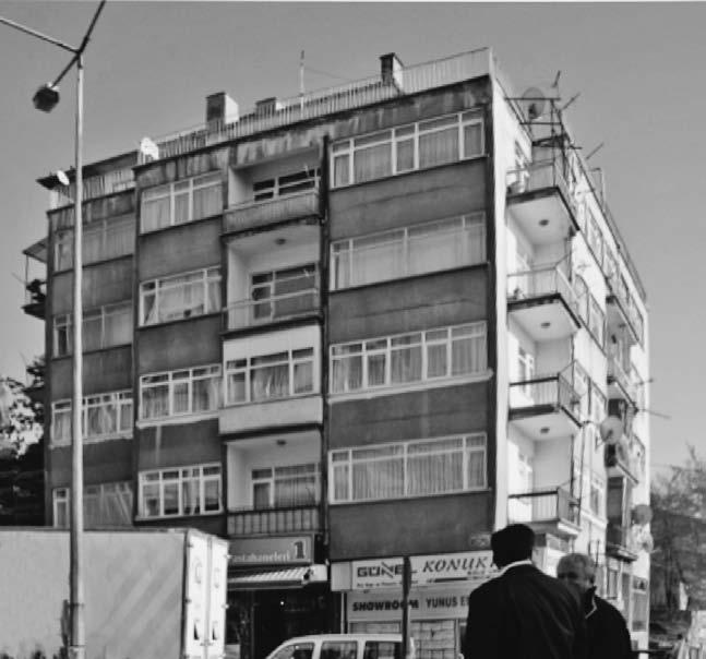
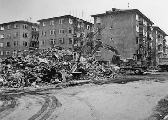
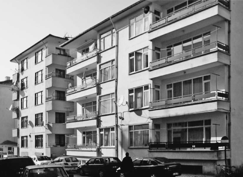
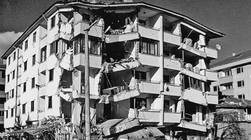
Fig. 1 Typical mid-rise RC buildings encountered within Turkey’s urban pattern and the result of earthquake damage in the form of total or partial collapse
Advertisement
Cengiz Özmen
Çankaya University, Faculty of Architecture, Department of Architecture, Ankara, Turkey, ORCID: 0000-0003-3372-5975 Çankaya Üniversitesi, Mimarlık Fakültesi, Mimarlık Bölümü, Ankara, Türkiye cengizozmen@cankaya.edu.tr
Preliminary Communication https://doi.org/10.31522/p.29.1(61).4 UDC 72.011:728:699.841 (560) ”20” Technical Sciences / Architecture and Urban Planning 2.01.01. - Architectural Design 2.01.03. - Architectural Structures, Building Physics, Materials and Building Technology Article Received / Accepted: 8. 6. 2021. / 18. 6. 2021.
Reconciling Architectural Design with Seismic Codes
A Comparative Architectural Analysis for Mid-Rise Reinforced Concrete Residential Buildings in Turkey
architectural design reinforced concrete residential buildings seismic code seismic design
Seismic codes include strict requirements for the design and construction of mid-rise reinforced concrete residential buildings. These requirements call for the symmetric and regular arrangement of the structural system, increased cross-sections for columns, and the introduction of shear walls to counteract the effects of lateral seismic loads. It is challenging for architects to reconcile the demands of these codes with the spatial arrangement and commercial appeal of their designs. This study argues that such reconciliation is possible through an architectural analysis. First, the effectiveness of applying the seismic design principles required by the codes is demonstrated with the comparative analysis of two finite element models. Then three pairs of architectural models, representing the most common floor plan arrangements for such buildings in Turkey, are architecturally analyzed before and after the application of seismic design principles in terms of floor area and access to view. The results demonstrate that within the context defined by the methodology of this study, considerable seismic achievement can be achieved in mid-rise reinforced concrete residential buildings by the application of relatively few, basic design features by the architects.
introduCtion1
From the Dinaric Alps to the Taurus Range, countries like Croatia, Greece and Turkey face a common threat: the earthquake. The 2020 Zagreb and Petrinja earthquakes, of magnitude 5.5 and 6.4 respectively, caused serious damage and loss of life in Croatia. Tyrnavos in Greece was hit by a 6.3 magnitude tremor in 2021. In Turkey, Elazığ had a 6.7 magnitude shock and İzmir was quite heavily damaged by a 7.0 magnitude quake in 2020, which also took 116 lives. These countries are no stranger to earthquakes and their effect on the built environment. Eurocode 8 is in effect in Croatia. As part of the EU, Greece has also adopted Eurocode 8 but has its seismic design practice rooted in EAK 2000/2003 (Pitilakis, Riga and Roumelioti, 2016: 437). Turkey, on the other hand, has its own code, the 2018 Turkish Earthquake Code (TEC 2018). While these codes are of critical interest to all stakeholders in the building sector, they are written and formulated by structural engineers for structural engineers. This is understandable because engineers are primarily responsible for ensuring the structural safety of buildings under seismic actions. Architects have a significant and often decisive role in the design of a building’s structural system but are often relegated to a secondary role in seismic codes (Özmen and Ünay, 2011: 919). This does not prevent the seismic codes from having a significant impact on various aspects of architectural design ranging from spatial arrangement to commercial appeal for potential customers. This study focuses on problems faced by architects in reconciling the requirements of the seismic codes with the spatial arrangements and commercial aspects of their designs. Turkey is the most populous country in the Mediterranean section of the Alp-Himalayan seismic belt. Furthermore, a large percentage of its urban and industrial centers are on either the north Anatolian fault zone or the Aegean horst-graben valleys. This, coupled with the rapid and uncontrolled urbanization rate, makes the country especially vulnerable to earthquakes (Özmen and Ünay, 2007: 1406). Despite the significant improvements in both technical and legislative aspects of seismic design after the devastating 1999 GölcükAdapazarı and Bolu earthquakes, the state of the existing building stock is far from being adequately resistant to possible future seismic events (İlki and Celep, 2012: 366). Midrise reinforced concrete [RC] residential buildings of three to eight storey's are by far the most common building type encountered in the urban and semi-urban areas of the aforementioned region (Oyguç, Oyguç and Tonuk, 2018: 3063). As a result of being the most common type of building, several RC residential buildings were either damaged or collapsed during earthquakes despite the heavy emphasis on ensuring the safety of these structures within the seismic codes (Tapan et al, 2013: 610). The scope of this study encompasses the earthquake-resistant architectural design aspects of the mid-rise reinforced concrete residential buildings in Turkey. In the last twenty-five years, Turkey has brought into force three earthquake codes: in 1997, 2007 and 2018. These regulations incorporated the latest scientific knowledge and technological developments in earthquake-resistant design. However, it is not possible to completely solve the problems in the field with a seismic code. The shortcomings of seismic codes in solving the seismic resistance problem are numerous but two are closely related with the scope of this research. The first is the poor construction quality and workmanship, especially in reinforced concrete residential buildings. Turkey has vast technical knowledge, engineering infrastructure and experience in both rein-
1 The archival documents and models presented in this study are partially based on the unpublished thesis, titled A Comparative Structural and Architectural Analysis of Earthquake Resistant Design Principles Applied in Reinforced Concrete Residential Buildings in Turkey submitted to the Middle East Technical University by the author. The subject matter, the methodology and the bibliography are updated and adapted to the state of current developments in seismic design in Turkey.
forced concrete production and seismic design, but the scale and the clandestine nature of new building production means that many of these structures get neither adequate design services nor access to skilled labor. Despite the construction inspection law passed in 2001, this problem persists to this day (Yazgan et al, 2016: 595). The second reason is economic. The resources required to transform the existing building stock into an earthquake-resistant one, either via retrofitting or by rebuilding, are simply beyond the budgetary means of the state. As a result, an urban transformation law was passed in 2012 to make use of the private sector’s economic potential and inherent dynamism. This law allowed individual entrepreneurs to cooperate directly with property owners in the retrofitting and rebuilding of RC buildings (Daşkıran and Ak, 2015: 264). This process is slow and exacerbates the problems stemming from the sheer volume of ongoing construction projects. To compensate for the lack of adequate design services and ensure the safety of buildings, even when there are deficiencies in the construction and material quality, the codes have found no other remedy but to impose gradual but significant increases in the cross-sections of reinforced concrete structural elements (AFAD, 2018: 114). This is a problem for architects who have to ensure the earthquake safety of the buildings they design but also have to deliver the same spatial and commercial value to their clients within the same amount of space available to them. Retrofitting and rebuilding are the two common choices available in the seismic improvement of the urban environment. The scope of this study is focused on the rebuilding option for two reasons. Firstly, the involvement of architects is much extensive when the rebuilding option is selected by the property owners, as this process requires a complete redesign of the building. Retrofitting option may include the increase of structural cross-sections, addition of new structural elements and minor alterations to the spatial layout of a building however it is mostly an engineering-intensive process because it involves seismic assessment processes and application of selected strengthening methods as described in earthquake codes. This is done by structural engineers. Secondly, although retrofitting is the cheaper solution and preserves the existing building stock with all inherent architectural and heritage values, rebuilding option is more widely promoted by the government and the private stakeholders in Turkey. The reason behind this tendency is also an economic one. Building industry is the primary sector driving the economic growth of the country. From a governmental point of view, removing an old building and replacing it with a new one stimulates the economy on a larger scale. For the private industry there is more money to be made and the property owners get to own a brand new earthquake proof building with a considerably higher real estate value. It must be stated that retrofitting is the more sustainable option with a lesser impact on the urban environment and the preservation of natural resources however in the case of Turkey economic factors are more dominant.
MetHodologY
The audience for this paper is architects, not structural engineers; therefore, the methodology of this study is formulated to make seismic design principles both simple and intelligible for architects as well as guide them in the earthquake-resistant design of midrise RC residential buildings. At first, a literature survey was conducted to determine the main reasons for the poor seismic performance of RC buildings in Turkey. Among the many reasons which contribute to the failure of RC buildings those that are most related with the architectural design decisions are selected for this study. These factors are the asymmetric and irregular arrangement of structural elements, the presence of torsion, the lack of shear walls and the exceeding of column capacities due to insufficient element cross-sections. Second step includes the proof of concept. At this stage, the aim is to demonstrate to the architectural audience that regular and symmetrical arrangement of structural members; use of shear walls and increase in structural cross-sections significantly improves the seismic behavior of mid-rise RC buildings. In this demonstration a set of two finite element models representing a typical mid-rise RC building before and after the implementation of seismic improvements was analyzed. The seismically defective finite element model is simplified and adapted from a RC building destroyed during the 1999 Bolu-Düzce earthquake the structural plans of which are obtained from the local municipality. The original building did not survive the earthquake and no known photographs exists. The building possessed the general characteristics of the existing building stock in Turkey (Fig. 1). In order to make the results clear and simple, secondary architectural features that do not directly affect the seismic performance such as the staircase details are omitted in the model. The results of the finite element analysis prove that the architectural design improvements in the aforementioned areas greatly improve the seismic behavior of the modeled structure. Since this study focuses on the architectural discussion of seismic de-
sign principles, once this demonstration is made, the same architectural design principles can be applied to other buildings of comparable function and size without further need for structural analysis for each case. In this way the study can focus I detail on the architectural characteristics of typical mid-rise RC residential buildings rather than structural calculations. In the third step, a comparative architectural analysis was conducted on three pairs of architectural models, representing RC buildings with two, three and four residential units on each floor. These are the most common type of plan arrangements in Turkey due to the typical size of building blocks in Turkish urban zoning. The first architectural model is intentionally selected as the same one modeled in the finite element analysis to better relate the structural discussion with the architectural one. The second and third architectural models are also simplified and adapted from RC buildings destroyed during the 1999 Bolu-Düzce earthquake. All of the models are purposefully selected to have at least one angled façade that introduces a certain level of asymmetry to the structure. The first models in each pair represent the architectural designs containing seismic design faults and the second models represent the same building redesigned according to earthquake-resistant design principles. The models in each pair will be comparatively analyzed in terms of architectural criteria such as the floor area of the residential units, the number of rooms and the orientation of rooms. These architectural criteria are selected because of the critical role they play in the purchasing decisions of the average house owner or new buyer in Turkey. In each architectural model pair, while the usable spaces, the circulation spaces like corridors inside the residential units and buildings’ general circulation spaces vary in terms of area, the total floor area of the buildings remains unchanged. The outer shape of the buildings is preserved except small changes in the locations of balconies and indentations. This ensures that the new design can be implemented in the site of the old building without any change in urban parameters. The comparative analysis demonstrates that it is possible to obtain the same number of residential units with the same number of rooms and orientations while adhering to earthquake-resistant design principles. Based on the results, it can be argued that it is possible for architects to reconcile the demands of seismic codes and their clients by adhering to a set of simple structural design principles. The ability to fit the same number of residential units within the same building site may not appear as a significant achievement at first, however the urban transformation law in Turkey and the resulting rebuilding of mid-rise RC residential buildings was accompanied by ample debate and often legal action caused by property owners’ discontent with the decreasing number of residential units, lesser floor areas, room numbers and room sizes of their homes before and after the reconstruction. This study aims to address this current and popular problematic in Turkey with a simple comparative demonstration showing that the preservation of the spatial quality is possible through the careful implementation of basic architectural design principles.
struCtural PrinCiPles of eartHquaKe resistant arCHiteCtural design
The reasons for seismic failures of RC structures are numerous and cannot be addressed in their entirety in this paper. The most common occurrence is a combination of deficiencies in strength, ductility and lateral rigidity caused by poor design and construction or by poor material quality. These deficiencies result in the loss of stability and the collapse of the entire structure (Özmen, Akan and Ünay, 2011: 449). Seismic codes offer several remedies to prevent such a failure mechanism. These include the selection of much larger reference earthquakes for design than many buildings would realistically face during their lifetime, bringing generous safety coefficients in the estimation of seismic loads and establishing stringent rules for the detailing of reinforcement bars (Ersoy, 2013: 1702). The responsibility for application of a large majority of these seismic design rules lies squarely within the domain of structural engineers. However, many of the precautions that ensure lateral stability and the prevention of torsional displacements fall within architects’ design decisions in the form of symmetric and regular configuration of vertical structural members (Özmen and Katipoğlu, 2015: 15). This symmetry and regularity requirement is highly recommended but not strictly required by TEC 2018. The seismically improved versions of the finite element and architectural models in this study are configured to be as symmetrical and as regular as possible within the constraints of their site shapes. Seismic code requirements often result in a significant increase in the number and crosssections of vertical load-carrying members such as columns and shear walls as well as a mandate to design RC frames that are as symmetrical and as regular in plan as possible. Such an increase in the cross-sectional area of vertical members with an emphasis on symmetry and regularity directly impacts the architectural design of residential buildings (Ünay and Özmen, 2006: 260). The main
defense of RC buildings against the large shear forces created by earthquakes is the use of shear walls in each direction (Özkul et al, 2019: 74). An empirical value of shear wall area equal to 1% of the floor area in each cardinal direction, obtained from observations of RC buildings undamaged in past earthquakes is often mentioned in scientific literature (Burak and Çömlekçioğlu, 2013: 1928). This rule of thumb, however, does not exist in any of the Turkish earthquake codes past or present (Günel, 2013: 2). The use of shear walls is nevertheless a critical seismic design feature for mid-rise RC buildings because observations made during past earthquakes in Turkey demonstrate that columns often fail in resisting seismic shear forces due to the lack of ductile behavior even though ductility is a key requirement in TEC 2018 (Oyguç, 2016: 828). Shear wall inadequacy was a key observation in the case studies that were the basis of the aseismic versions of finite element and architectural models and therefore the improved models were designed with a large number of shear walls placed in both longitudinal and transverse directions. Torsion is an undesirable effect in the seismic behavior of RC structures (Gökdemir et al, 2013: 714). Torsional displacements can occur due to eccentricities in the building’s center of rigidity or they can be the result of a building’s irregular plan shape. Eccentricities in the building’s center of rigidity can stem from uneven or asymmetrical distribution of columns and shear walls. In this case, the direction and location of the shear walls become especially critical. A building can theoretically have enough shear walls to satisfy the “1% of the total floor area in each direction” rule of thumb but these walls may be arranged in such a way that the building still suffers from torsional eccentricity. In urban areas, irregularities in plan geometry may be unavoidable due to the shape of the building site. In this case, the responsibility falls to the architect to design a structural system that counteracts the resulting torsion by arranging the configuration of vertical loadcarrying elements such as columns and shear walls. In the first finite element model the building suffers from both of the above-mentioned problems. The building sits on a site with an irregular shape and its columns and shear walls are arranged in a way that introduces eccentricity to its center of rigidity. In the improved version of the finite element model, the torsion problem is solved by the regular and symmetrical arrangement of vertical structural elements as well as the introduction of additional shear walls. The aseismic versions of the architectural models all exhibit the same problems in terms of torsional eccentricity. In the seismically improved versions structural configurations are arranged to counteract torsion based on the principles obtained from the finite element analysis. In the seismic design of reinforced concrete buildings, making sure that the structural system remains stable during and after the shock is very important (Bikçe and Çelik, 2016: 71). In TEC 2018, RC buildings are allowed to have plastic deformations during large earthquakes. This is a precaution that ensures a high level of ductility in the entire system. The system is designed so that these deformations occur in pre-calculated locations. These locations are the supports of the RC beams where they are connected to columns. The columns, on the other hand, are not allowed to have plastic hinges under any circumstances. This is ensured by the increase in column cross-sections (Oyguç, Toros and Abdelnaby, 2018: 31). The interaction diagram between the columns’ axial force and bending moment capacity is a simple and clear way of establishing an idea about their seismic behavior. In mid-rise RC residential buildings this interaction becomes critical in the lower supports of the columns where the vertical system is connected to the foundations (Korkmaz, Yakut and Bayraktar, 2019: 47). Another critical factor is the prevention of large lateral displacements (Arslan et al, 2018: 325). As a result, the two finite element models will be analyzed and evaluated according to the performance of selected columns at the ground floor before and after seismic design improvements and the amount of decrease in the maximum displacements on the top floor corners of the building. Material properties for reinforced concrete and reinforcement, as well as the detailing of reinforcements, are assumed to be in accord with TEC 2018 (Balun, Nemutlu and Sarı, 2020: 175).
CoMParative analYsis of tHe finite eleMent Models
In this section two architectural models (Model-A and Model-B) will be comparatively analyzed to evaluate their structural performances before and after seismic improvements. The first finite element model (Model A) represents a 6-storey RC residential building. Floor height is taken as 3 meters resulting in an 18-meter high mid-rise structure (Fig. 2). This is a typical building in urban and semi-urban areas in Turkey and the Balkans. An irregularity in the form of an angled front façade is introduced to its geometry due to the site shape. The structure contains a single shear wall located around the elevator shaft. The remainder of the columns is arranged in an asymmetric and irregular pattern to accommodate two residential units on each floor. These residential units consist of
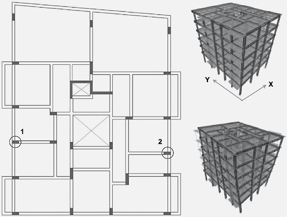
Table I Dominant movement directions, periods and maximum displacements for Model A
Model A
Mode Movement T (s) d-max (m)
1st Mode Torsion 0.84 2nd Mode Lateral (x-dir) 0.72 0.092
3rd Mode Lateral (y-dir) 0.65 0.081 Fig. 2 The structural system of Model A. Plan configuration (left), undeformed shape (top-right corner), deformed shape (lower-right corner). Column capacities are measured for the columns marked 1 and 2 respectively.
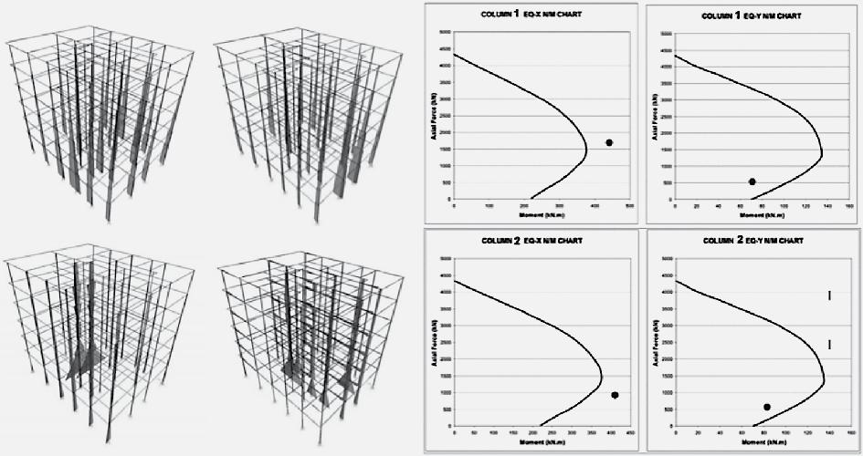
Fig. 3 Axial force diagrams in both earthquake directions for Model A (upper left corner), moment diagrams in both earthquake directions for Model A (lower left corner), column capacity diagrams for column 1 (upper right corner), column capacity diagrams for column 2 (lower right corner) one master living room, three bedrooms, one kitchen, one bathroom and a guest toilet. The ground floor is allocated to commercial functions and the building’s entrance. The model is subjected to seismic loading in both earthquake directions as described in TEC 2018.2 A basic analysis is conducted to measure the structure’s response to the first three oscillation modes, maximum lateral drifts and column capacities for axial force and bending moment. In Model A, the asymmetric and irregular arrangement of columns results in torsional displacements. There is a single shear wall and the column cross-sections are small. This results in a structural system with very low lateral rigidity, which in turn causes relatively high periods for the first three modes. For a building of this height, the high periods are the indication of large and uneven displacements in both earthquake directions (Table I). The internal force diagrams of Model A indicate that, in accordance with expectations, axial forces reach their highest levels at the lower ends of columns located on the outer periphery of the building. Similarly, bending moments become critical at the same locations but near the columns located at the center of the structure. Two columns, columns 1 and 2, were selected to represent the behavior of the slender vertical elements under seismic loading. These columns were selected among the outer periphery columns, which are more prone to failure due to torsional displacements. The analyses indicate that these two columns would pass into the failure zone in at least one of the two earthquake directions under the applied loads (Fig. 3). The second finite element model (Model B) represents the same 6-storey RC residential
2 TEC 2018 is a 395 page document that incorporates seismic design principles inherited from the past Turkish seismic codes, EUROCODE 8 and ASCE 7-16 as well as other prominent seismic codes. Because TEC 2018 generally favors the most structurally demanding methods, it would be safe to assert that any mid-rise RC residenial building designed according to TEC 2018 would also be considered seismically safe according to the requirements of EUROCODE 8 and ASCE 7-16. TEC 2018 is used in conjunction with The Interactive Turkish Earthquake Map system which can only be accessed by Turkish citizens and authorized personnel through the “E-Devlet” governmental e-state web service. As the concept of “earthquake zones” are abolished by TEC 2018, this service provides official site-specific parameters to be used in the drawing of the vertical and horizontal elastic spectrum curves for each structure. These parameters include the regional ground acceleration values for the reference earthquake and the soil type among others. The elastic spectrum curves used for the finite element models analyzed in this study are drawn with the assumption that the structures are in a high-risk area with a reference earthquake occurence period of 475 years, subjected to ground acceleration levels near 0,4g and built on a medium-strength soil type that does not require special calculation methods.
building modeled in Model-A, however; the structure is redesigned with shear walls and columns with larger cross-sections, arranged in a regular and symmetrical configuration. Floor height and total building height remains unchanged (Fig. 4). The residential units also consist of one master living room, three bedrooms, one kitchen, one bathroom and a guest toilet. The ground floor is allocated to commercial functions and the building’s entrance. The model is subjected to the same seismic loading as in Model-A in both earthquake directions as described in TEC 2018. Same basic analysis is conducted to measure the structure’s response to the first three oscillation modes, maximum lateral drifts and column capacities. In the second finite element model (Model B), the directionality of vertical structural elements is distributed equally for the two earthquake directions. This eliminates torsional displacement in the first mode. Lateral sway of the building is significantly less than in the first model, which indicates that vertical elements do not approach structural failure zones (Table II). The internal force diagrams of Model B indicate that, like in to Model A, axial forces reach their highest levels at the lower ends of columns located on the outer periphery of the building. Bending moments also reach their highest values at the same locations but near the shear walls. Two columns, located at similar locations with Model A, were selected to represent the behavior of columns in the seismically improved version of the model. The analyses indicate that these two columns would remain safe in both earthquake directions under the applied loads. The safety margins are quite large for these columns. This is due to the existence of shear walls, which carry the major portion of the seismic effects and alleviate the structural strain on more slender elements like columns (Fig. 5). The analyses conducted on the two finite element models demonstrate the effectiveness of the structural design principles in increasing the seismic performance of mid-rise RC residential buildings. The symmetric and regular arrangement of the structural system, larger cross-sections for columns and the existence of evenly distributed shear walls significantly increase the safety of RC buildings. Additionally, the building represented in the seismically improved Model B offers an equivalent architectural value in terms of usable floor area and directional orientation of rooms to Model A. This analytical demonstration of the increase in earthquake safety coupled with the preservation of architectural value forms the basis of the comparative architectural analysis in the following section.
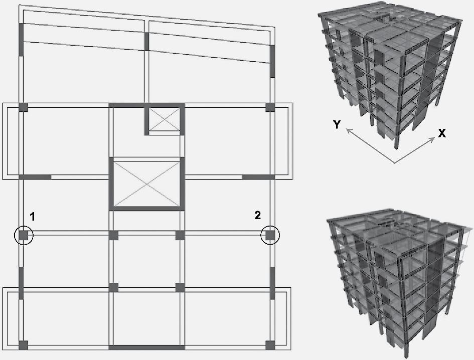
Fig. 4 The structural system of Model B. Plan configuration (left), undeformed shape (top-right corner), deformed shape (lower-right corner). Column capacities are measured for the columns marked 1 and 2 respectively.
Fig. 5 Axial force diagrams in both earthquake directions for Model B (upper left corner), moment diagrams in both earthquake directions for Model A (lower left corner), column capacity diagrams for column 1 (upper right corner), column capacity diagrams for column 2 (lower right corner) Table II Dominant movement directions, periods and maximum displacements for Model B
Model B
Mode Movement T (s) d-max (m)
1st Mode Lateral (y-dir) 0.46 0.056
2nd Mode Lateral (x-dir) 0.45 0.047
3rd Mode Torsion 0.33 -
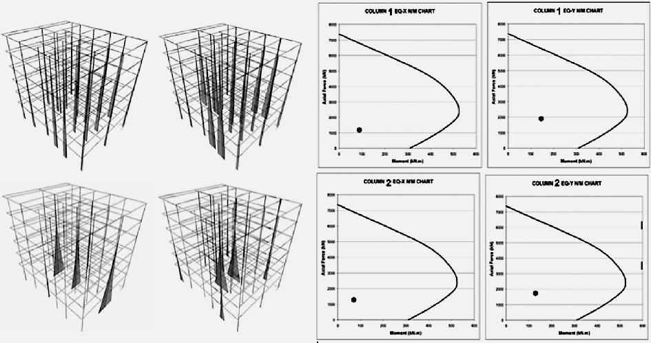
Table III Architectural evaluation of Set 1a-1b in terms of floor area and access to façade
Res-A
Set 1a Set 1b Room m2 Façade m2 Façade
Living Room 36 Front 36 Front Room 17 Side 16 Side Room 13 Side 12.5 Side Room 13 Side 12 Side Dress room - - 9 N/A Kitchen 13.5 Side 13 Side Bathroom 7 - 7 N/A WC 3 - 3 N/A Usable Area 102,5 108,5
Res-B Set 1a Set 1b Room m2 Façade m2 Façade Living Room 38 Front 32 Front Room 18 Side 16 Side
Room
15 Side 1.,5 Side Room 13 Side 12 Side Dress room - - 9 Kitchen 13.5 Side 13 Side Bathroom 7 Side 7 WC 3 - 3 Usable Area 107,5 104,5
Fig. 6 On left: Set 1a, architectural plan (above) and structural system (below) with seismic design faults. On right: Set 1b, architectural plan (above) and structural system (below) are seismically improved.
CoMParative analYsis of tHe arCHiteCtural Models
In this section three architectural model pairs (Set 1a-1b, Set 2a-2b, Set 3a-3b) will be comparatively analyzed to evaluate their architectural qualities before and after seismic improvements. These models represent the plan configurations of typical RC residential buildings from Turkey. They have two, three and four residential units on each floor respectively. It is assumed that all floors except the ground floor have the same floor plan.
• Architectural model pair with two residen-
tial units on each floor (Set 1a-1b) - Set 1a-1b is based on the previously analyzed finite element Models A and B. The two residential units will be called Res-A and Res-B. These residences are “three plus ones” as they are colloquially called in Turkey, meaning there is a master living room and three smaller rooms. There is also a kitchen, a bathroom and a guest toilet in the unit (Fig. 6). The floor plan of Set 1a represents a typical approach to residential unit design in Turkey. The structural system’s configuration is completely secondary to the spatial needs of the individual units. The master living rooms are as large as possible and equal in size to each other in accordance with the expectations of future customers. This attempt to have a large living room in the less spacious Res-B is the main reason behind the asymmetric and irregular arrangement of the structural system. The second reason is the effort to avoid visible overhanging beams in the ceilings of
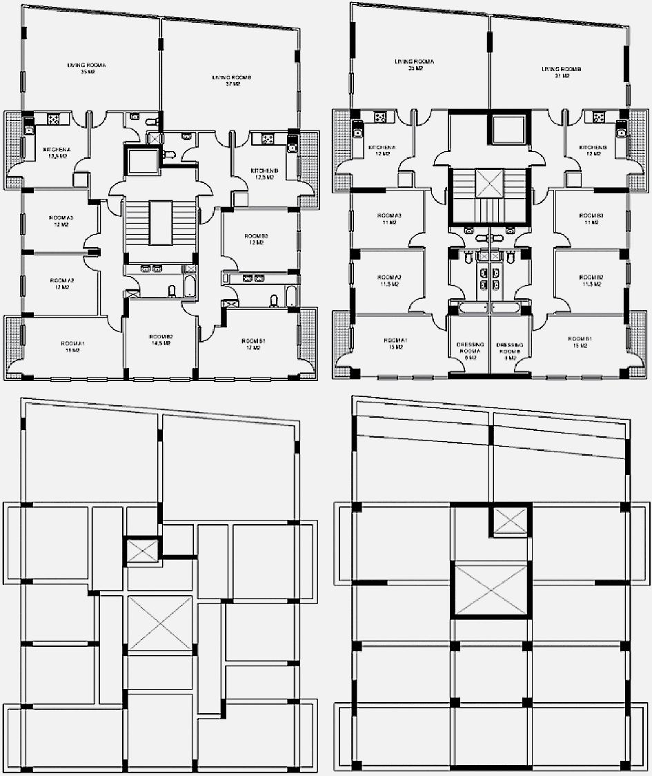
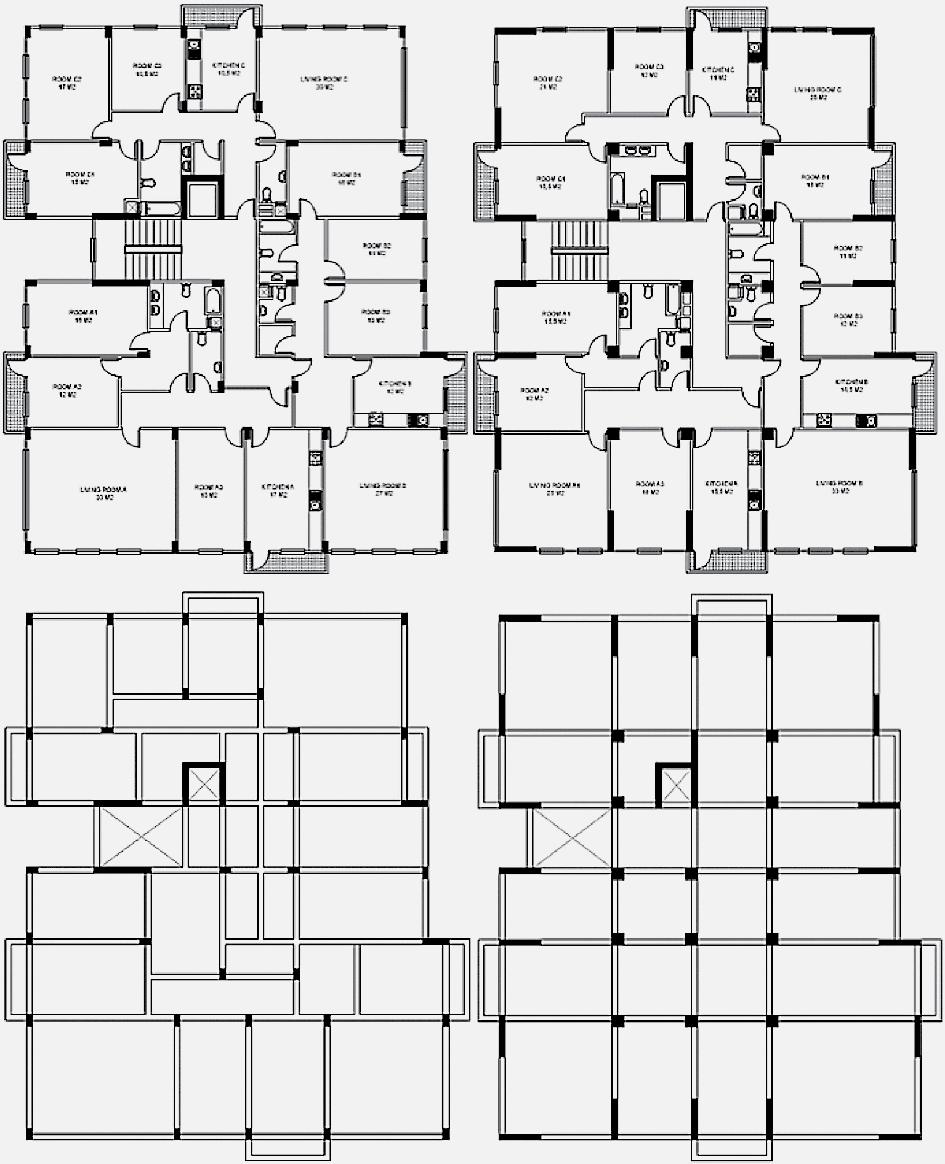
Table IV Architectural evaluation of Set 2a-2b in terms of floor area and access to façade
Res-A
Set 2a Set 2b Room m2 Façade m2 Façade
Living Room 34 Rear 26 Rear Room 17 Rear 16.5 Rear Room 13 Rear 13 Rear Room 16 Side 19 Side Kitchen 18 Side 16.5 Side Bathroom 7 - 8 WC 3.5 - 3.5 Storage - - - Usable Area 108.5 102.5
Res-B Set 2a Set 2b Room m2 Façade m2 Façade
Living Room 28 Rear 34 Rear Room 17 Rear 16 Rear Room 12 Rear 12 Rear
Room 14 Side 13 Side Kitchen 13 Side 15 Side Bathroom 5.5 - 6.5 WC 2 - 3 Storage 3 - 3.5 Usable Area 94.5 103
Res-C
Set 2a Set 2b Room m2 Façade m2 Façade
Living Room 31 Front 26 Front Room 16 Rear 16.5 Rear Room 18 Rear 22 Rear
Room 11.5 Side 13 Side Kitchen 11.5 Side 12 Side Bathroom 7 N/A 7.5 N/A WC 3 N/A 2 N/A Storage 2.5 N/A 3 N/A Usable Area 100.5 102
rooms and circulation spaces due to aesthetic concerns. The architectural plan of Res-B suffers further from the large space allocated for the master living room. The third room of Res-B is shifted to the rear façade of the building due to the shorter length of the side façade. In turn, the bathroom is shifted from the center of the plan to the side. As a result, the wet spaces of Res-A and Res-B are positioned away from each other, making the mechanical systems of the building more complicated and inefficient (Fig. 6). In Set 1b, the main architectural compromise is having a smaller master living room for Res-B. This one compromise allows for the design of a symmetric and regular structural system. Column cross-sections become larger and shear walls are arranged in both earthquake directions. Structural axes are straight and unbroken in every direction. A shallow beam was added between the columns around the master living room to ensure structural connectivity in all frame members. The symmetric and regular structural system allows for similar arrangement of rooms for Res-A and Res-B and even creates enough space for a dressing room in the master bedrooms of both units. The wet spaces of Res-A and Res-B are arranged together, allowing them to share the same mechanical shafts and plumbing systems creating a more efficient design (Fig. 6). The two architectural models of Set 1 are comparatively analyzed in terms of their usable floor areas and access to view. There are no significant changes in the spatial configu-
Fig. 7 On left: Set 2a, architectural plan (above) and structural system (below) with seismic design faults. On right: Set 2b, architectural plan (above) and structural system (below) are seismically improved.
Table V Architectural evaluation of Set 3a-3b in terms of floor area and access to façade
Res-A Set 3a Set 3b Room m2 Façade m2 Façade
Living Room 28 Front 31 Front Room 12 Front 15 Front Room 16.5 Front 23.5 Front Room 13.5 Side 14.5 Side Kitchen 8.5 Side 9.5 Side Bathroom 8.5 - 7 WC 3 - 2.5 Usable Area 90 103
Res-B Set 3a Set 3b Room m2 Façade m2 Façade
Living Room 23 Rear 24 Rear Room 12.5 Rear 13 Rear Room 15 Rear 17 Rear Room 14.5 Side 14.5 Side Kitchen 8 Side 9.5 Side Bathroom 8.5 - 8 WC 3 - 2.5 Usable Area 84.5 88.5
Res-C
Set 1a Set 1b Room m2 Façade m2 Façade
Living Room 30 Rear 26 Rear Room 12 Rear 13 Rear Room 16 Rear 16.5 Rear Room 15 Side 17 Side Kitchen 11 Rear 10.5 Side Bathroom 8 - 8 WC 2.5 - 2.5 Usable Area 94.5 93.5
Res-D Set 1a Set 1b Room m2 Façade m2 Façade
Living Room 32.5 Front 24 Front Room 12 Front 15 Front Room 16.5 Front 15 Front Room 16 Side 17 Side Kitchen 8 Side 10.5 Side Bathroom 8 - 8 WC 2.5 - 2.5 Usable Area 95.5 92
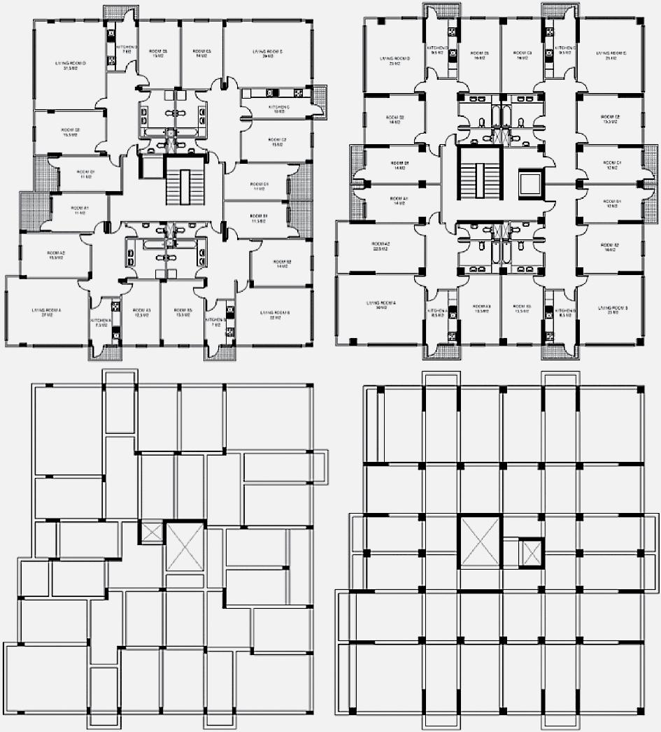
Fig. 8 On left: Set 3a, architectural plan (above) and structural system (below) with seismic design faults. On right: Set 3b, architectural plan (above) and structural system (below) are seismically improved. ration of Res-A before and after the seismic improvements. There are small decreases in the sizes of the rooms due to the increasing sizes of structural elements. These variations would not negatively affect the use of these rooms. Both Res-A and Res-B gained a dressing room next to their master bedrooms. Spatial arrangement of Res-B is significantly improved after the redesign, which compensates for the loss in the size of the master living room (Table III).
• Architectural model pair with three resi-
dential units on each floor (Set 2a-2b) - Set 2a-2b has three residential units on each floor. These three residential units will be called Res-A, Res-B and Res-C. These residences are also “three plus ones” with a master living room and three smaller rooms. There is also a kitchen, a bathroom and a guest toilet in each residence. Res-B and ResC have small storage rooms (Fig. 7). The floor plan of Set 2a suffers from the same problems with the residential units from Set 1a. The master living rooms are again designed as large as possible and equal in size even though these units are separate and will be occupied by different users having different spatial needs. The structural system is asymmetric and irregular. The cross-sections of columns are small. There are two shear walls located on both sides of the building’s main stairwell. These shear walls would have very little positive contribution to the seismic behavior of the building. In fact, the eccentric location of the shear walls would probably result in torsional displacements creating large bending moments and shear forces on the columns located on the opposite side of the building. In Set 2b, a symmetric and regular structural system is designed to the extent that is allowed by the irregular shape of the building
site. Column cross-sections become larger and shear walls are arranged in both earthquake directions. Shear walls are located around the outer periphery of the structural system. This building will be subjected to torsion due to the site shape. This arrangement of shear walls on the outermost axes will allow them to counter the shear forces and bending moments resulting from the torsional displacements during the earthquakes. Structural axes are straight and unbroken in every direction (Fig. 7). The two architectural models of Set 2 are comparatively analyzed in terms of their usable floor areas and access to view. The only significant change in the spatial configurations of Res-A and Res-C, before and after the seismic improvement, is in the floor area of the master living room. This is a necessary compromise to have an earthquake-resistant structural system. The decrease in the size of these spaces is not significant enough to upset their function as the primary living area of the residential units. In contrast, Res-B now has a larger master living room. There are small variations in the sizes of the rooms in all three units. These variations would not negatively affect the use of these rooms. Overall, the building represented in Set 2b offers the same three residential units with comparable floor areas and access to view with a much higher level of earthquake safety (Table IV).
• Architectural model pair with four resi-
dential units on each floor (Set 3a-3b) - Set 3a-3b has four residential units on each floor. These three residential units will be called Res-A, Res-B, Res-C and Res-D. These residences are also “three plus ones” with a master living room and three smaller rooms. There is also a kitchen, a bathroom and a guest toilet in each residence (Fig. 8). The floor plan of Set 3a suffers from the same problems as the models Set 1a and Set 2a. The master living rooms are again designed as large as possible and equal in size. The structural system is asymmetric and irregular. A certain amount of asymmetry is present, however most of the irregularity arises from the effort to shape the building structure according to the spatial configuration. The continuity of structural axes was not prioritized. The cross-sections of columns are small and there are only two shear walls, one located on both sides of the elevator and one near the building’s main stairwell. The eccentric location of the shear walls would result in torsional displacements (Fig. 8). In Set 3b, the structural system is redesigned according to the seismic design principles. Symmetry, regularity, and the continuity of structural axes are provided in both earthquake directions. Column cross-sections became larger and shear walls are arranged in both earthquake directions. Shear walls are located around the outer periphery of the structural system. Like Set 2b, shear walls are arranged on the outermost axes to counteract the effects of the torsional displacements on the outermost columns of the building (Fig. 8). The two architectural models of Set 3 are comparatively analyzed in terms of their usable floor areas and access to view. Res-A is the only unit that becomes significantly larger with respect to its original floor area. ResB, Res-C and Res-D do not vary in terms of total floor area. The only significant change in the spatial configuration of Res-D, before and after the seismic improvement, is in the floor area of the master living room. This is an undesirable but necessary compromise to have an earthquake-resistant structural system. In contrast, Res-B now has a larger master living room. There are overall increases in the sizes of the rooms in all four units, which would make these residences more valuable in terms of customer evaluation. The building represented in Set 3b, while having somewhat more drastic design changes from its original design compared to the buildings represented in Set 2b and Set 1b, still offers an earthquake-resistant architectural solution containing the four residential units with commercially acceptable floor areas and access to view (Table V).
ConClusion
Mid-rise RC residential buildings are a common typology in Turkey and the wider Balkans region and as such the design of these buildings constitutes a sizable portion of almost every architect’s portfolio. Unfortunately, the past seismic performance of these buildings was very poor, especially in Turkey. Seismic codes have continuously brought new and stricter requirements for the design and construction of these buildings. Many of these requirements such as the calculation methods, numerical modeling principles, and detailing of RC members were oriented towards the structural engineering domain, however these new requirements also resulted in some direct and indirect changes in the way architects design their buildings. This study has the aim of making the seismic design principles for mid-rise RC buildings clear and understandable for architects. In this context the following points can be stated about the strengths and limitations of the methodology and the main outcomes: • The factors affecting the seismic performance of a RC building are numerous. Only a portion of these factors is directly related
with the architects’ design decisions. A further prioritization can be made among these to determine the most influential parameters. Such an approach is necessary to render the propositions of the study understandable and applicable by a wider architectural audience. This study states that the symmetric and regular arrangement of structural elements, the avoidance of torsional irregularity, the use of shear walls and the increase in column cross-sections are the most influential parameters. This decision is soundly based on the existing seismic codes’ requirements, scientific literature and the current state of the construction industry in Turkey. Since the topic of seismic design is multifaceted and interdisciplinary in nature the prioritization of the most critical seismic design factors can be done with other points of view in different contexts. • The effectiveness of selected seismic design criteria is demonstrated via finite element modeling on a single building. This model was simplified and adapted from a building that did not survive a past earthquake. The simplifications included the omission of minor architectural details such as the non-structural components and the exclusion of staircase details from the model. In this regard the model can be considered a semiidealized version. This adaptation and simplification is made to emphasize the effect of the aforementioned seismic design criteria on the structural performance of the structure and avoid the main discussion to be sidetracked minor details. Such an idealization approach may not be suitable for an engineering audience but it is critical to convey the desired message clearly to architects. • The finite element analysis is conducted for a single case while the discussions on the other two models are kept at architectural comparison level. The reason for this limitation was to keep the discussion focused on the architectural design aspect of seismic design. The application of the selected seismic design criteria to the finite element model demonstrated the effectiveness of the proposed improvements. The structure represented in the finite element models is a typical example of the mid-rise RC residential buildings in Turkey. It does not include exceptional design features and formal characteristics that would introduce case specific seismic design considerations. Therefore, it is possible to generalize the results obtained from the comparative finite element analysis to other RC buildings of similar function, size and formal characteristics. This study does not state that case specific structural analyses are not needed for the design and construction of RC buildings in architectural practice but it argues that if the seismic design principles proposed here are implemented by architects from the beginning of the architectural design process it is highly probable that seismic analyses done by the engineers will prove that these buildings are firmly within the seismic safety limits. It must be stated here that mid-rise RC residential structures built on sites with specific topographic features or shapes that impose highly irregular formal characteristics to the building are excluded from the scope of this study. • This study is conducted within the context of the built environment and the factors driving the urban policies and the construction industry in Turkey however the seismic design principles proposed here are context independent and can be implemented by architects within comparable contexts such as the Balkans and the wider Mediterranean regions. • The comparison criteria selected for the architectural models are the floor area of the residential units, the number of rooms and the orientation of rooms. This study does not have a reductionist approach, which bases the architectural value of buildings on basic plan features and the amount of usable areas in residential units. The selection of these criteria is merely based on the decision-making habits of the property owners in Turkey, which is echoed by the typologies produced by the building industry. • The findings of this study has be deemed successful in proving that, within the context defined by the methodology, considerable seismic improvement can be achieved in midrise RC residential buildings by the application of relatively few, basic design features by the architects. These design features are the symmetric and regular arrangement of structural elements, the avoidance of torsional irregularity, the use of shear walls and the increase in column cross-sections. Furthermore, the study demonstrates that the application of these features is possible through architects’ design decisions. • The findings of this study will contribute to the ongoing debates about the improvement of the existing aseismic building stock through urban transformation processes in the sense that designing a mid-rise RC residential building with a more robust structural system with somewhat restricting features in terms of plan arrangement is not an insurmountable obstacle in preserving the architectural expectations of the property owners from their new buildings. In short, this study demonstrates that architects who have an awareness of some basic but fundamental seismic design principles can design earthquake resistant homes for existing property owners on the site of their existing buildings without
any losses in the aforementioned architectural parameters. As a final word, it must be acknowledged that, the scope of architects’ involvement in alternative seismic improvement methods such as retrofitting can be explored and comparatively analyzed with respect to the rebuilding method. The economic and urban impact of more culturally sustainable approaches to urban transformation is also a valid direction for further studies, as the concern for the preservation of architectural heritage is an ever-increasing one in the rapidly transforming cities of 21st century. [Proofread by Stephen Bryant]
Author’s biography
Cengiz ÖzMen, Architect, Ph.D., is an Associate Professor of Architecture at the Faculty of Architecture in Çankaya University, Ankara. He received his M.Sc. and Ph.D degrees from the Building Science Program in Middle East Technical University, Ankara. His academic interests are Architectural Design, Structural Design and Seismic Design.
The conceptualization, establishment of methodology, literature review, data collection, structural analysis, architectural analysis, writing and visualization of this paper are done by the author.
Bibliography and Sources
1. AFAD- Afet ve Acil Durum Yönetimi Başkanlığı (2018) ‘Türkiye Bina Deprem Yönetmeliği’, Resmi Gazete (https://www.resmigazete.gov.tr/ eskiler/2018/03/20180318M1-2-1.pdf), 30364 2. Arslan, G., Börekçi, M., Şahin, B., Denizer,
İ.M. and Duman, K.S. (2018) ‘Performance Evaluation of In-Plan Irregular RC Frame Buildings
Based on Turkish Seismic Code’, International
Journal of Civil Engineering, 16, pp. 323-333, https://doi.org/10.1007/s40999-016-0131-1 3. Burak, B. and Çömlekoğlu, G. (2013) ‘Effect of
Shear Wall Area to Floor Area Ratio on the Seismic Behavior of Reinforced concrete Buildings’,
Journal of Structural Engineering, 139 (11), pp. 1928-1937, https://doi.org/10.1061/(ASCE)
ST.1943-541X.0000785 4. Balun, B., Nemutlu, Ö.F. and Sarı, A. (2020)
‘TBDY 2018 Basitleştirilmiş Tasarım Kurallarının
Taban Kesme Kuvvetine Etkisinin İncelenmesi’,
Turkish Journal of Nature and Science, 9, pp. 178-181, https://doi.org/10.46810/tdfd.749257 5. Bikçe, M. and Çelik, T.B. (2016) ‘Failure Analysis of Newly Constructed RC Buildings Designed
According to 2007 Turkish Seismic Code during the October 23, 2011 Van Earthquake’, Engineering Failure Analysis, 64, pp. 67-84, https:// doi.org/10.1016/j.engfailanal.2016.03.008 6. Daşkıran, F. and Ak, D. (2015) ‘6306 Sayılı Kanun Kapsamında Kentsel Dönüşüm’, Yönetim ve Ekonomi Araştırmaları Dergisi, 13 (3), pp. 264-288, https://doi.org/10.11611/JMER674 7. Ersoy, U. (2013) ‘A Simple Approach for Preliminary Design of Reinforced Concrete Structures to be Built in Seismic Regions’, Teknik
Dergi, 24 (4), pp. 6559-6574 8. Gökdemir, H., Özbaşaran, H., Doğan, M., Ünlüoğlu, E. and Albayrak, U. (2013) ‘Effects of Torsional Irregularity to Structures During
Earthquakes’, Engineering Failure Analysis, 35, pp. 713-717, https://doi.org/10.1016/j.engfailanal.2013.06.028 9. Günel, A.O. (2013) ‘Influence of the Shear Wall
Area to Floor Area Ratio on the Seismic Performance of Existing Reinforced Concrete Buildings’, Master of Science, Middle East Technical
University, Graduate School of Natural and Applied Sciences 10. İlki, A. and Celep, Z. (2012) ‘Earthquakes, Existing Buildings and Seismic Design Codes in Turkey’, Arabian Journal for Science and Engineering, 37 (2), pp. 365-380, https://doi.org/10. 1007/s13369-012-0183-8 11. Korkmaz, H.H., Yakut, A. and Bayraktar, A. (2019) ‘Analysis of a Multi-Story Reinforced
Concrete Residential Building Damaged under
Its Self-Weight’, Engineering Failure Analysis, 98, pp. 38-48, https://doi.org/10.1016/j.engfailanal.2019.01.043 12. Oyguç, R. (2016) ‘Seismic Performance of RC
School Buildings after 2011 Van Earthquakes’,
Bulletin of Earthquake Engineering, 14, pp. 821-847, https://doi.org/10.1007/s10518-0159857-4 13. Oyguç, R., Oyguç, E. and Tonuk, G. (2018) ‘Case
Study on Seismic Behavior of Aseismically Designed Reinforced Concrete Frame Structures’,
Bulletin of Earthquake Engineering, 16, pp. 3057-3080, https://doi.org/10.1007/s10518017-0300-x 14. Oyguç, R., Toros, Ç. and Abdelnaby, A.E. (2018) ‘Seismic Behavior of Irregular Reinforced-Concrete structures under Multiple Earthquake Excitations’, Soil Dynamics and Earthquake Engineering, 104, pp. 15-32, https: //doi.org/10.1016/j.soildyn.2017.10.002 15. Özkul, T.A., Kurtbeyoğlu, A., Börekçi, M.,
Zengin, B. and Koçak, A. (2019) ‘Effect of Shear
Wall on Seismic Performance of RC Frame Buildings’, Engineering Failure Analysis, 100, pp. 60-75, https://doi.org/10.1016/j.engfailanal. 2019.02.032 16. Özmen, C., Akan, A.E. and Unay, A.I. (2011)
‘Proračun povijesne zidane zgrade : Analysis of a Historical Masonry House’, Građevinar, 63 (5), pp. 449-458 17. Özmen, C. and Ünay, A.I. (2011) ‘Architect-Structural Engineer Collaboration in Sustainable
Structural System Design’, Gazi University Journal of Science, 24 (4), pp. 919-925 18. Özmen, C. and Ünay, A.I. (2007) ‘Commonly Encountered Seismic Design Faults in Reinforced
Concrete Residential Architecture in Turkey’,
Building and Environment, 12 (3), pp. 14061416, https://doi.org/10.1016/j.buildenv.2005. 09.029 19. Özmen, C. and Katipoğlu, C. (2015) ‘The Role
Of Scaled Models And Computer Simulations In
Architectural Education’, International Refereed
Journal Of Design And Architecture, 4 (2), pp. 1324, https://doi.org/10.17365/TMD.201549620 20. Pitilakis, K., Riga, E. and Roumelioti, Z. (2016)
‘The Urgent Need for an Improvement of the
Greek Seismic Code Based on a New Seismic
Hazard Map for Europe and a New Site Classification System’. In: Kavvadas, M. (ed.) Jubilee
Volume: Andreas Anagnostopoulos, 50 Years of
Service at the National Technical University of
Athens. Athens: Tsotras, pp. 437-461 21. Tapan, M., Cömert, M., Demir, C., Sayan, Y.,
Orakcal, K. and İlki, A. (2013) ‘Failures of Structures During the October 23, 2011 Tabanlı (Van) and November 9, 2011 Edremit (Van)
Earthquakes in Turkey’, Engineering Failure
Analysis, 34, pp. 606-628, https://doi. org/10.1016/j.engfailanal.2013.02.013 22. Ünay, A.İ. and Özmen, C. (2006) ‘Building Structure Design as an Integral Part of Architecture: A
Teaching Model for Students of Architecture’,
International Journal of Technology and Design
Education, 16, pp. 253-271, https://doi.org/ 10.1007/s10798-005-5241-z 23. Yazgan, U., Oyguç, R., Ergüven, M.E. and Celep, Z. (2016) ‘Seismic Performance of Buildings
During 2011 Van Earthquakes and Rebuilding
Efforts’, Earthquake Engineering and Engineering Vibration, 15 (3), pp. 591-606, https://doi. org/10.1007/s11803-016-0346-9
Illustrations source


