
of Heating, Refrigerating and Air-Conditioning Engineers, Inc. It is presented for educational purposes only. This article may not be copied and/or distributed electronically or in paper form without permission of ASHRAE.
TES Without Ice
By Daniel Pare, P.E., Associate Member ASHRAE; and Stephane Bilodeau, Ph.D., P.E., Member ASHRAEIn1971 IBM built a semiconductor manufacturing facility in Bromont, a small town in the Eastern Townships, about 62 miles (100 km) from Montréal, Québec. Located in a rural setting on 1,000 acres (405 ha) of land, this 800,000 ft2 (74 322 m2) plant primarily assembles semiconductors on substrates to ultimately create microprocessors.
More than 25 years ago, IBM set an annual objective of reducing energy consumption by 4%. IBM Bromont has consistently achieved this target and saved nearly 500,000 MWh in the last 15 years, taking into account an erosion factor of 20% per year.
Although the company’s energy conservation program has been profitable
for the Bromont plant, it is becoming increasingly difficult to meet the 4% energy savings objective. Therefore, we must use cutting-edge techniques.
The project described in this article is a good example of an innovative solution combining several technologies including phase change materials (PCM), a warm weather natural cooling exchanger and a
variable frequency drive (VFD) chiller with a nominal capacity of 1,500 tons (5275 kW).
This project began when IBM Bromont had to change its 25-year-old chillers that ran on R-12. In fact, under Québec law, as of Jan. 1, 2006, any chiller running on R-12 must be decommissioned in the year following a repair. Environmentally conscious, IBM Bromont decided on a solution that would allow the plant to
About the Authors
Daniel Pare, P.E., is an advisory engineer for IBM Canada, Bromont, PQ, Canada. He won a 2007 ASHRAE Technology Award for this project.
Stephane Bilodeau, Ph.D., P.E., is president and CEO of Groupe Enerstat. He is an associate professor in the mechanical engineering department at the University of Sherbrooke, Sherbrooke, PQ, Canada.
46 ASHRAE Journal ashrae.org July 2007
The
Journal, July
©Copyright
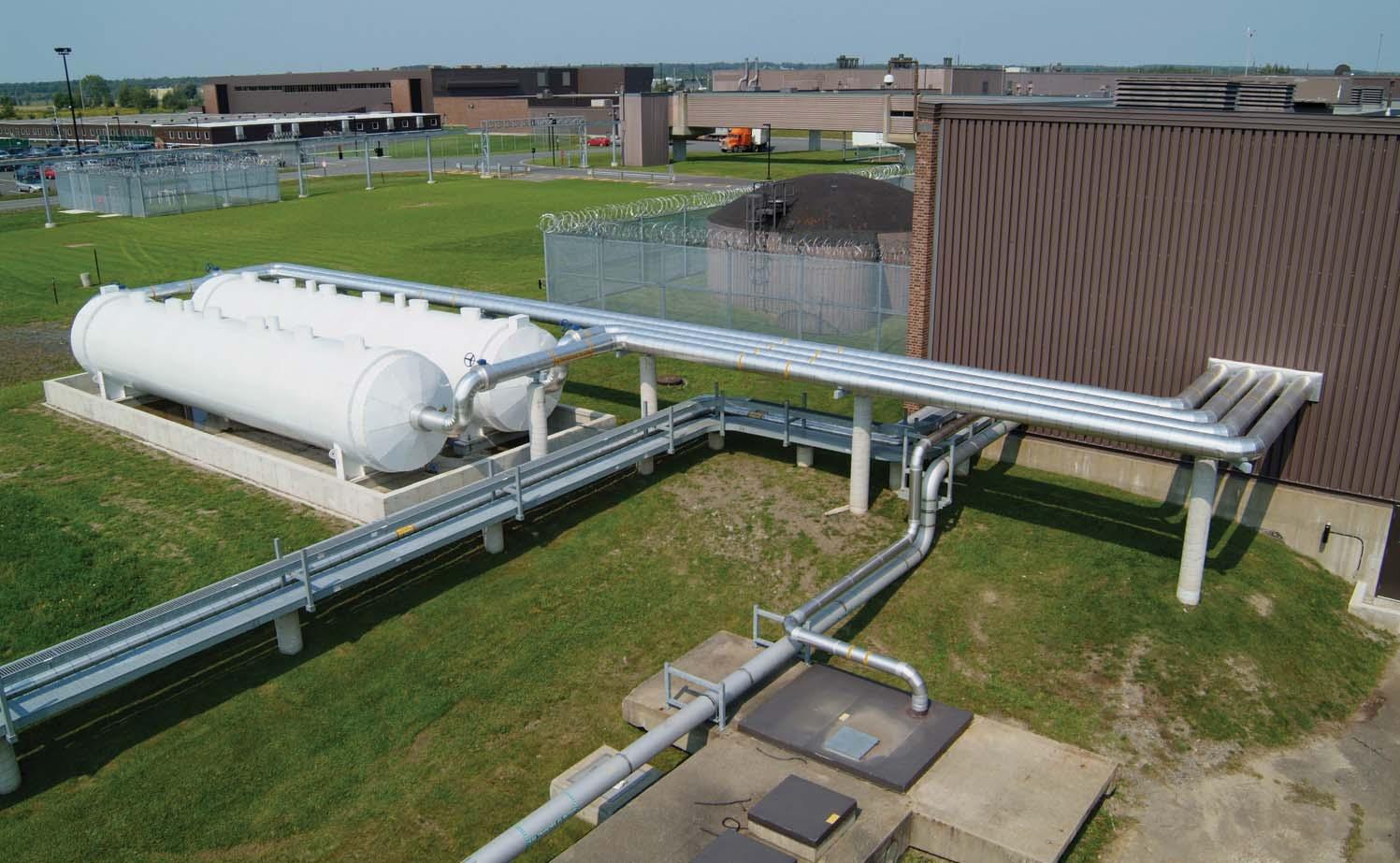
TES storage at IBM-Bromont plant.
following article was published in ASHRAE
2007.
2007 American Society
modernize the chillers and realize substantial energy savings. The energy savings associated with this project are about 6% annually and will generate savings of 5,300 MWh/year, as well as reduce electrical power consumption by more than 1 MW. This is the most ambitious energy savings project ever undertaken at Bromont.
Context and Project Description
In early 2005, the Bromont power plant had six 1,000 ton (3517 kW) chillers, two 2,000 ton (7034 kW) chillers and a natural cooling exchanger of approximately 1,000 tons (3517 kW). The latter typically ran from December 15 to March 15.
Of the six 1,000 ton (3517 kW) chillers, three operated on R-12. Because it had been decided to change two of these units to comply with the law, we had to replace the equivalent of 2,000 tons (7034 kW) of cooling capacity.
The project consists of a 1,500 ton (5275 kW) capacity VFD chiller, two 1,600 ton·hour (5627 kW) PCM thermal energy storage (TES) tanks, a 2,500 ton (8792 kW) capacity plate exchanger, a system comprising of 25% glycol and two pumps (one VFD 4,300 gpm [271 L/s] on the process water system and one 3,000 gpm [189 L/s] on the glycol circuit). The shortfall of 500 tons (1758 kW) between the new chiller and the two R-12 chillers is offset by the PCM TES tank.
Before going further, a definition of PCM is in order. PCMs are substances that can accumulate and release latent energy during a phase change. In this particular case, we are referring to a change from liquid to solid and vice versa. PCMs are found in nature; ice is one example. The melting point of ice is 32°F (0°C). However, it is possible to create artificial PCMs, which have a melting point ranging from –40°F (–40°C) to more than 250°F (121°C).
In our project, we have two TES tanks with artificial PCMs with different melting points, i.e., 28°F and 40°F (–2°C and 4°C). These temperatures were selected to maximize system efficiency.
Unlike ice, artificial PCMs are excellent conductors. In fact, ice is a good insulator that reduces the efficiency of the thermal transfer during phase changes. In an ice storage tank, we know the first few inches are easy to produce compared to the last few. Conversely, melting ice is difficult at the beginning. Therefore, a TES tank using ice instead of artificial PCMs is larger and the energy transfer is slower.
Ice expands during the phase change from liquid to solid. However, this is not the case with artificial PCMs because they

have a negative expansion factor during this phase change and, therefore, do not place stress on the exchangers.
Operation
We were convinced that a PCM TES tank was essential to maximize the efficiency of the future system. However, we found it difficult to obtain management support on such a major project without a proven basis regarding the operation of PCMs. Therefore, we installed a small PCM TES tank at the outlet of a hot water/steam exchanger that was experiencing temperature control problems. The exchanger supplied emergency showers and was prone to strong flow fluctuations (sudden changes of 2 to 40 gpm [0.1 to 2.5 L/s]) and temperature problems. The phase change system behaved exactly as expected. We managed to stabilize the temperature regardless of water consumption. Now, we had to reproduce the same system on a bigger scale. A TES tank automatically requires the use of a secondary loop. Given that we wanted to operate at temperatures below 32°F (0°C), we used 25% glycol. And, we used a chiller that better suited our energy expectations. This chiller would allow us to regulate the glycol output temperature and optimize energy efficiency throughout this temperature range. We regulated the glycol temperature between 28°F to 36°F (–2°C to 2°C) depending on the mode (load or unload). Therefore, we opted for a VFD chiller with a nominal capacity of 1,500 tons (5275 kW), which is the largest chiller of its kind in Canada. We installed two TES tanks on the loop; one above and one below the chiller. Set at 40°F (4°C), the storage tank above regulates the chiller load and is always in operation; it can be unloaded/reloaded several times a day. The tank below the chiller is set at 28°F (–2°C) and is used to support substantial long-term fluctuations. Used in bypass or line mode, it is loaded/unloaded one to two times a day. This loop also contains a 2,500 ton (8792 kW) plate exchanger for glycol/process water, an exchanger that is fed by a 3,000 gpm (189 L/s) fixed-flow pump. We did not need this pump to be equipped with a VFD.
The water process circuit contains the 2,500 ton (8792 kW) plate exchanger fed by a 4,300 gpm (271.3 L/s) VFD pump. With a VFD pump and plate exchanger, you can regulate the cooling load at approximately 100 tons (352 kW), preventing another chiller from starting up at part-load conditions or when the pressure drops in the process water circuit. In fact, in the past, we started up a chiller to compensate for the lack of pressure in the system even if the cooling load was satisfactory,
July 2007 ASHRAE Journal 47
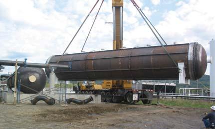
PCM storage tank installation.
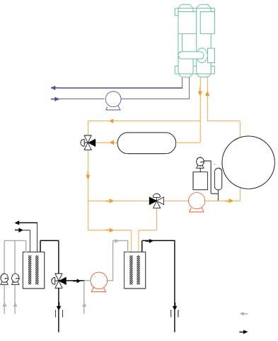
thereby reducing energy efficiency. The end effect was to create a short circuit between supply and return, reducing the return temperature and chiller efficiency (Figure 1).
This system integrates the natural cooling exchanger that can be placed next to the TES system. This is possible because the 2,500 ton (8792 kW) plate exchanger brings the water temperature back to its setpoint. In the past, we had to turn off the plate exchanger when the outside temperature prevented us from obtaining the desired temperature of about 40°F (4°C). Before the installation integration of the TES, this exchanger was typically in operation from December 15 to March 15. We came up with the idea for this exchanger after we completed an ASHRAE online training course in March 2004 (Compliance with ANSI/ASHRAE/IESNA
Standard 90.1 HVAC and Service Water Heating). In fact, it is cost effective to take advantage of this free cooling because the TES allows us to use the exchanger for more than 3,000 additional hours per year. From now on, this free cooling exchanger will run from September to May.
Energy Efficiency
To maximize the energy efficiency of our cold production, we used an approach recognized by ASHRAE for thermal storage called partial storage.1 With this approach, mechanical systems are operated to handle part of the load in peak periods. The rest of the demand (excess) is handled by the TES tank. The size of the mechanical equipment can be reduced so the installed capacity corresponds to an average consumption value below typical design conditions. Partial storage has allowed us to limit thermal energy production despite strong fluctuations in demand.
The partial storage strategy requires that the mechanical equipment operate 24-hours-a-day during peak demand periods. This strategy is particularly effective when peak demand is much stronger than usual.2 When demand is lower than the mechanical capacity, the surplus energy is stored; whereas, when demand exceeds the installed capacity, thermal storage handles the demand. This approach, referred to as load-leveling, has allowed us to minimize the required capacity of our equipment and the storage tank for a given demand level.
A control strategy that constantly computes the heat balance and predicts peak loads was developed specifically for the project. The strategy uses an improved partial storage approach to maximize the demand-limiting advantage. The TES microcontroller system was integrated into the plant’s energy management system. The two systems continuously exchange information to keep the process operating at optimal performance.
In short, the cooling medium, in our case glycol, circulates at a rate of 3,000 gpm (1894 L/s) in the storage tank (accumulator). This fluid provides or draws thermal kWh by changing the state of the PCMs (from liquid to solid and vice versa), depending on the system’s loading or unloading needs.
Other elements that contributed substantially to reducing energy consumption are as follows:
High-efficiency mechanical compression (1,500 ton [5275 kW] VFD chiller). Simultaneously using low-temperature tanks and a continuously running high-performance compressor al-
lows us to reduce partial loads. Our consumption ranges from 0.4 to 0.6 kW/ton compared to 0.9 kW/ton, without PCM. The difference between the partial load and the nominal capacity of the equipment in place is handled by the two TES tanks.
Reducing the average temperature of the condenser by running a larger cooling operation at night (the temperature fluctuates approximately 20°F [11°C] at the Bromont site) allows us to boost the chiller’s additional performance by more than 15% kW/ton.
Natural cooling. The Bromont site was already equipped with a natural cooling exchanger. However, the energy storage system has allowed us to substantially increase this component’s cooling capacity from 750 tons (2638 kW) to a maximum of 1,250 tons (4396 kW).
When the outside temperature is too warm to use the natural exchanger, the precooled water from the natural exchanger is directed through the 2,500 ton (8792 kW) plate exchanger and the TES tanks. As mentioned earlier, we can regulate this exchanger at approximately 100 tons (352 kW), extending the natural cooling period from three months to nine months a year, adding more than 3,000 natural cooling hours. This operating principle greatly contributes to energy efficiency. For example, in May 2006 we obtained almost 1,000 tons (3517 kW) of free cooling on some days. Since it typically takes 0.9 kW/ton to produce chilled water, we cut our electrical consumption by 900 kW.
Table 1 shows the Bromont results. Chilled water production efficiency improved more than 45%, from 0.9 kW/ton to 0.45 kW/ton. Energy savings for the year amounted to 5,300 MWh, while peak consumption fell 1 MW.
48 ASHRAE Journal ashrae.org July 2007
Refrigeration
Condenser
Water
Water Tower Trench 42°F – 54°F (5.6°C – 12.2°C) Compensation Glycolic Water Water + Glycol Main Exchanger Water Free Cooling Exchanger Water P P P PCM Tank 2 28°F (2.2°C) PCM Tank 1 40°F (4.4°C) Supply Return Water
Unit
Evaporator
Tower Trench 65°F (18.3°C)
Figure 1: System operation schematic.
Innovation
The use of a thermal energy system with PCM combined with free cooling, VFD chiller and predictive algorithm control is a first. Given the project’s innovativeness, Natural Resources Canada and Hydro-Québec contributed financially to this “demonstration” project.
The project size is also a first. In fact, more than 40 million Btu (42.2 million kJ) are stored in the tanks during each load cycle. These tanks are 45 ft long (14 m) and 8 ft (2.5 m) in diameter. Conventional ice storage tanks would have been far larger for both thermal storage and heat transfer purposes. Artificial PCMs have a much better conductivity factor than their natural counterparts.
Operation and Maintenance
The system has proven to be easy to operate. It consists of a secondary loop with a cooling medium that loads/unloads a thermal storage tank. A three-way control valve together with a VFD pump allows operators to stop worrying about whether or not to start another chiller when pressure falls or when cooling demand surges.
The PCMs are kept in a sealed tank and require no maintenance. During the phase change, the temperature is kept constant regardless of the cooling load.
On several occasions power fluctuations caused the chiller to stop. The storage tank took over and kept the chilled water temperature at its setpoint, allowing the operators to re-establish operations more quickly and without deviating from the manufacturer’s specifications.
Environmental Impact
This load-leveling approach minimizes the need for equipment and storage capacity. In the Bromont project, this strategy has significantly improved energy use. Also, the effective integration of thermal storage has resulted in two major environmental impacts:
• A 50% reduction in refrigerant requirements upon dismantling the two 1,000 ton (3517 kW) R-12 chillers, which were replaced with one 1,500 ton (5275 kW) chiller using the much more environmentally friendly R-134a refrigerant; and
• A 45% reduction in GHG emissions for chilled water production due to an equivalent improvement in energy consumption.
These environmental benefits are a good example of how the management of a power plant can be optimized and how to contribute to a sustainable development plan, which was clearly a major issue for the IBM Bromont plant.
References
1. 2003 ASHRAE Handbook—HVAC Applications, Chapter 34, Thermal Storage.
2. MacCracken, M. 2004. “Thermal energy storage in sustainable buildings.” ASHRAE Journal 46(9):S2–S5.
Bilodeau, S. 2006. “Energy management in a chilled water plant using thermal storage.” 10th International Conference on Thermal Energy Storage.
Advertisement formerly in this space.
July 2007 ASHRAE Journal 49
General Performance Thermal Energy Production and Storage for the Chilled Water Loop Before (2004)After (2005 – 2006) Cooling Production 18,728 ton·hours/day37,537 ton·hours/day Daily Consumption 16,706 kWh/day 15,572 kWh/day Average Instant Consumption 696 kW 648.8 kW Average Cooling Production (PCM + VFD Cooler) 1,564.1 tons (5501 kW) Average Cooling Production 780.3 tons (2744 kW) Average Natural Cooling Production 750 tons (2638 kW) nominal less than 90% of the time 945 tons (3323 kW) average 1,250 tons (4396 kW) max Average Total Production1,455 tons (5117 kW)2,509 tons (8824 kW) Cooling Production Efficiency (Excluding Natural Cooling) 0.892 kW/tons 0.415 kW/tons Cooling Production Efficiency (Including Natural Cooling) 0.478 kW/tons 0.259 kW/tons Table 1: Monitoring data summary. Bibliography