5 minute read
Environment:Tri-Mer
Catalytic fi ltration in the glass industry
Martin Schroeter* explains how the versatility of catalytic fi ltration can become the recognised technology for stack emissions control within the glass industry.

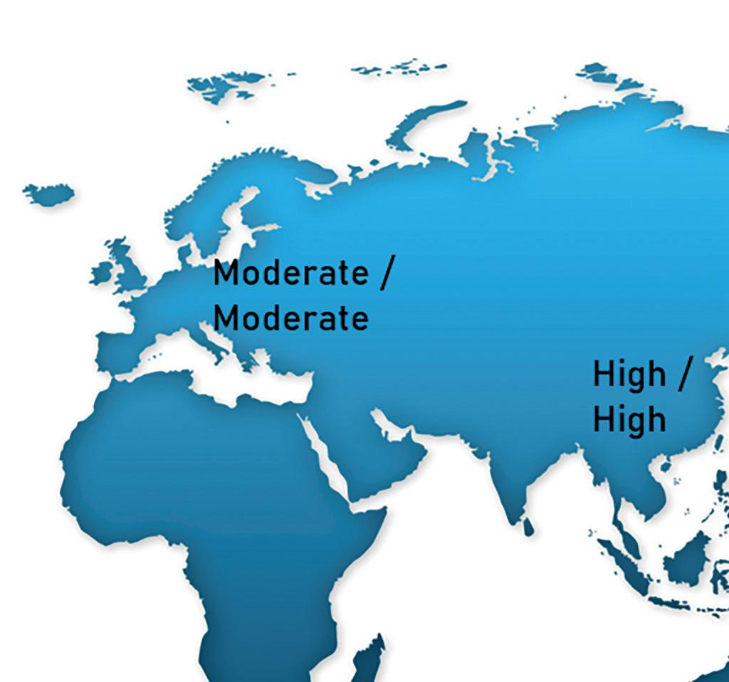
� Different regulatory requirements (removal effi ciency/system availability) in different geographies.

Today, catalytic fi ltration is a widely accepted technology for control of stack emissions in the glass industry.
Both in Europe and the USA, it holds a status of Best Available Control Technology (BAT / BACT) and became the preferred solution for control of NOx, SO2 and PM emission in Asia.
While the implementation of the catalytic fi ltration technology in the glass industry has been installed due to a variety of drivers across different geographies, this paper summarises the versatility of the technology to address those drivers and inspire upgrading solutions.
Versatility of the technology
One of the major characteristics of the catalytic fi ltration technology is its adaptability to accommodate different regulatory requirements.
The track record of the catalytic fi ltration technology began in Europe in the late 2000’s as an alternative solution to add NOx removal effi ciency up to 95% with negligible ammonia slip. This was a major concern for regenerative furnaces during fl ow reversal.
Four years later, the catalytic fi ltration technology was adopted for the glass industry in the USA, while it took further three years for the fi rst catalytic fi ltration system start-up in Asia.
At the heart of the technology is a fi lter candle made of ceramic fi bres, which allows operation at elevated temperature of up to 900°C (1,650°F).
The dust separation follows the principles of surface fi ltration on a conditioned layer, the “fi lter cake”. While dust removal is achieved with back pulse air, only part of the fi lter cake is detached and removed to the hopper section of the fi lter house.
Since the ceramic fi lter does not expand during back pulsing, a residual dust cake will always remain on the fi lter. The residual dust cake prevents any constituent of the particulate matter to penetrate into the fi lter wall and thus makes the fi lter wall the ideal location to place a fi nely dispersed DeNOx catalyst as it will be entirely protected from particulate blinding.
In combination with dry sorbent injection, typically using hydrated lime as the sorbent, the catalytic fi lter is now capable to control both fi lterable and condensable particulate matter, NOx and acid gas precursors, like SO2, SO3, HCl or HF, together with metals and HAPs falling in the category of acid type components.
While the catalytic fi ltration technology provides a high removal effi ciency for all targeted emissions, geographies with moderate regulatory requirements may still consider catalytic fi ltration as a forward-thinking solution, which will still meet present regulations and be prepared for future requirements.
This technology can also be used in combination with pre-existing emission control equipment -- adding emissions reduction capabilities by installing a partial fl ow treatment with catalytic fi ltration provides clients with a CAPEXeffi cient solution.
At the other end of the spectrum, combination with traditional technology, like an SCR DeNOx slip reactor downstream of the catalytic fi lter system, can provide highest removal effi ciencies


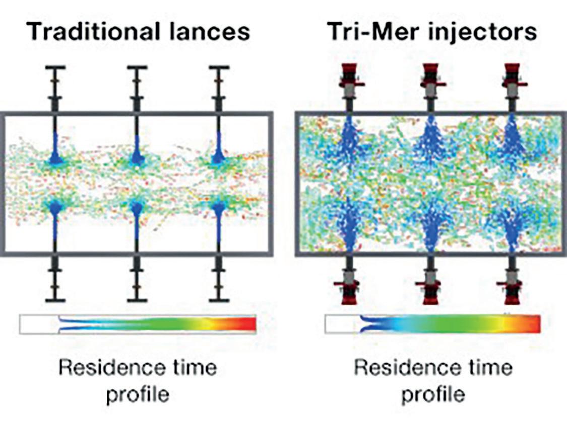
� CFD simulation of the mixing patterns and residence time profi le of high jet injection technology.
while keeping operational expenditures at a moderate level.
The desire to control operational expenditures did also inspire a number of technologies to minimise consumption of injected sorbent.
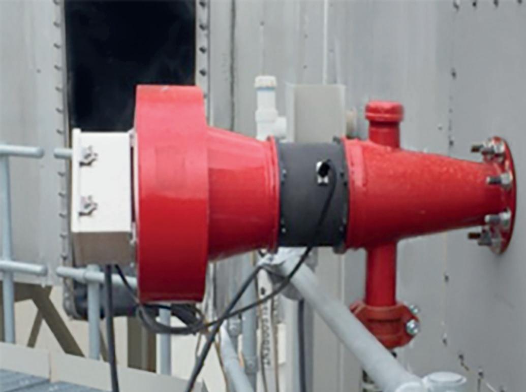
These technologies, like booster air assisted injection or waste recirculation technologies, target improving the sorbent utilisation, which is hindered by diffusion limiting scale formation of the reaction product, by increasing mixing, dispersion, and residence time.
Upgrading the overall system with these technologies can allow SO2 removal effi ciencies exceeding 97%, and/or reduction in sorbent usage exceeding 20%.
Availability has become another important factor when designing an emission control system. Driven by very limited permitted time for bypass operation of untreated exhaust gas in the USA, development of a cost-effi cient modular concept delivered the potential to full redundancy of the complete emission control system. Today, fi lter housing maintenance can be done “online”, isolating one housing by closing inlet and outlet dampers. The remaining fi lter housings are designed to allow operation at full capacity for a limited period of time. Additionally, by equipping all subsystems in a redundant way, like 3 half-fl ow ID-fans, maintenance of the emission control system becomes independent from furnace operation.
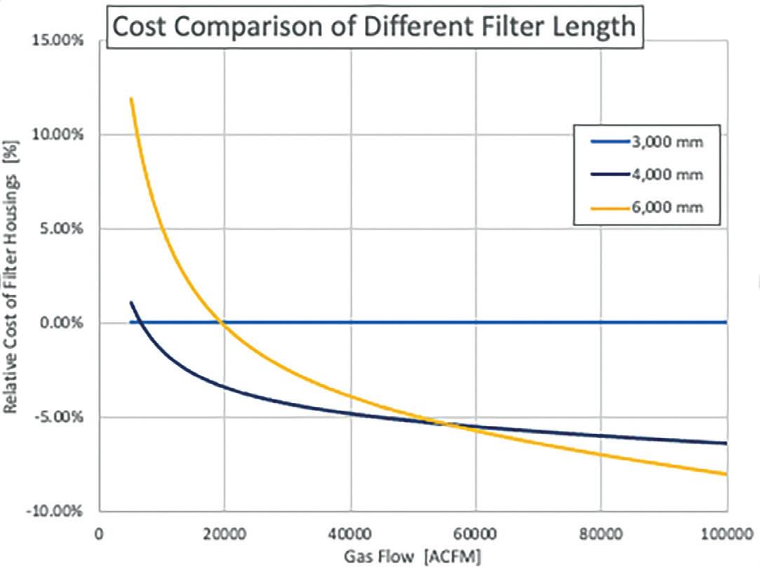
At the centre of the newest development is the fi lter candle itself. Larger exhaust fl ows and footprint restrictions have driven the development towards longer fi lter elements.
While shorter fi lter elements offer a cost-effective solution at lower exhaust gas volume fl ows, longer fi lter elements become the preferential choice at larger exhaust gas volume fl ows.
Longer fi lter elements also allow fi lter house design to accommodate future conditions, such as additional exhaust gas treatment for future capacity increase. This could be achieved by adjusting the fi ltration area at the time of capacity increase.
Conclusion
The catalytic fi ltration technology has developed fl exible design solutions to address varying regulatory requirements for the glass industry worldwide.
The technology has achieved a state of maturity allowing for the implementation of consequential design improvements for optimum total cost of ownership.
While the lifetime of the fi lter elements for the fi rst industrial systems was predicted to be much shorter, experience has shown that the fi lter elements can operate for more than 10 years.
New developments are focusing on operation and maintenance, striving for reduction of consumables and preventing mass fi lter breakage events with novel technology to prevent broken fi lter elements from sliding out of position.
In summary, the glass industry has fully adopted the catalytic fi ltration technology as a means to meet present emission control requirements, while also allowing clients to upgrade their systems to meet future requirements with reduced effort and cost. �
*Sales - Ceramics Technology Group (CTG) Tri-Mer Corporation, Owosso, USA https://tri-mer.com/
� Relative cost of fi lter housings depending on exhaust gas fl ow for different fi lter length.


