3 minute read
INSTALL RADIAFLEX WITH CONFIDENCE


Prevent Pim Interference To Maintain Overall System Performance
Radiating cables are distributed antennas and, consequently, metal obstacles in close proximity to the cable – notably to the radiating slots – may impact radiation behavior and might cause passive intermodulation (PIM) effects. This is especially true in scenarios where a metal dowel and the metal tie wrapped around the cable might make contact. PIM effects might significantly degrade overall system performance and KPI’s for wireless communication systems. In order to avoid metallic contact between the fire secured tie and the metal dowel, a plastic insert has been provided to ensure the highest possible robustness against PIM interferences.
Advertisement
Fire Protection Inserts
MODEL NUMBER USE SIZE
SFS-12-F for SFS-12-01 clamp (1/2”) L = 247 mm (9.72 in)
SFS-78-F for SFS-78-01 clamp (7/8”) L = 300 mm (11.81 in)
SFS-114-F for SFS-114-01 clamp (1-1/4”) L = 330 mm (12.99 in)
SFS-158-F for SFS-158-01 clamp (1-5/8”) L = 335 mm (13.18 in)
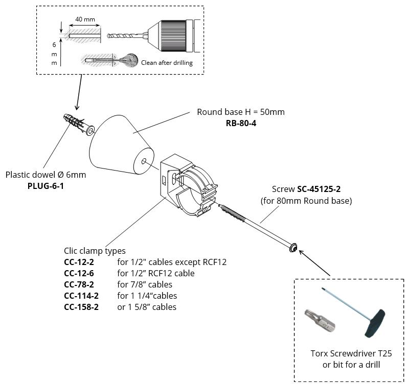
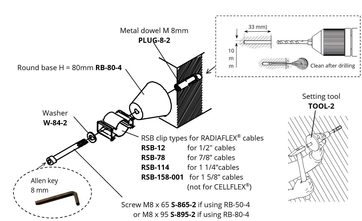
Clic Clamp Installation
RLK, RAY and RLV type RADIAFLEX cables require a round base with a height H = 80 mm. These clamps are fixed with a plastic plug Ø 6 mm and a stainless steel screw.
Care should be taken to ensure that the hole is always drilled at right angles to the surface of the wall so that the clamps do not become twisted during the subsequent assembly. The hole should be cleaned out with an air pump after drilling. The clamp is fixed by means of a round head wood-screw tightened with a TORX bit screw driver (T 25) or with a cordless electric screwdriver and corresponding TORX bit.
Make sure the clamps are lined up; otherwise the cable will not run in a perfectly straight line. The minimum bending radii for installing cables should also be taken into account when fixing the clamps. When attaching the cable, the action of pressing the cable into the clamp with the hand causes the clamp to close automatically.
Please refer to the datasheet of the individual cable to review the recommended clamp spacing.
Install Radiaflex With Confidence
Position
Pay attention to the bulge or guides on the cable jacket
CLIC-CLAMP
Mount the cables by simply pushing the cable in by hand. The clamp will grip and lock by applying light pressure
Install Radiaflex With Confidence
Safety Is Key
In case of fire, the resistant part of the fixing will hold the cable in position and enables the cable to keep in operation as long as the cable itself allows. It also prevents the cable from detaching from the wall which could block escape routes.
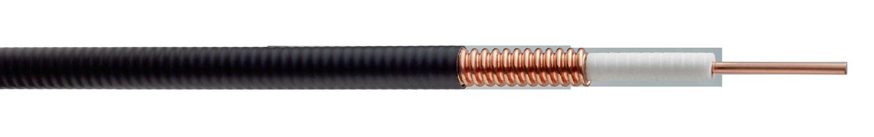
Radiaflex Overview Radiating Cable Basics
RFS RADIAFLEX cables support all services up to 6 GHz with high performance, making them ideal for multiband, multi-operator applications in the most challenging indoor and underground environments.
How They Work
• Coaxial cable designed and constructed to radiate and receive RF energy over it’s entire length.
• Designed to replace traditional antennas
• Ensure line of sight everywhere between radio system and antenna
• Combined with other indoor solutions products to enhance RF coverage
Frequency Range
The design of the apertures in the outer conductor influences the frequency for which the cable is optimized. RADIAFLEX® cables are usually classified into categories: for operation up to 960 MHz, 1900 MHz and 2700 MHz (6000 MHz). Cables optimized for special frequency ranges are available on request
Longitudinal Loss

This is a measure of signal loss in the cable over its entire length
Coupling Loss
This is a measure of the signal loss between the cable and a test receiver at a distance of 2m (6.5ft)
System Loss
This is the sum of longitudinal loss and coupling loss
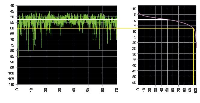
Reception probability
50% - where 50 percent of all measured samples are better than stated performance figures
95% - where 95 percent of all measured samples are better than stated performance figures
NORMAL RF CABLE
RF Power
RADIATING CABLE
Transmitting (downlink)
Receiving (uplink)
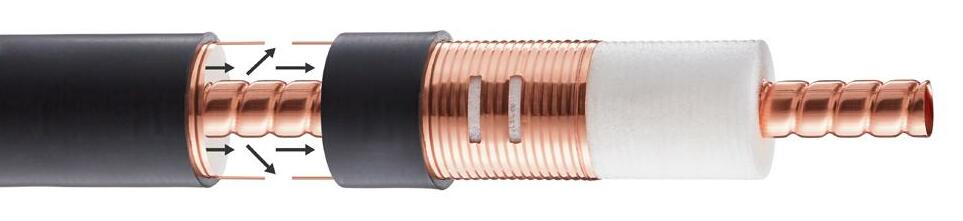
How Is This Done
By cutting holes or slots in the outer conductor of coaxial cables, enabling RF power to enter or leave the cable.


LONGITUDINAL LOSS AI SIGNAL LOSS IN CABLE
Radiaflex Overview Radiating Cable Basics
Example: al = 3
COUPLING LOSS AC SIGNAL LOSS BETWEEN CABLE AND MOBILE DEVICE
Radiaflex Overview Radiating Cable Basics
ACCORDING TO IEC 61 196-4
Standard measurement along a cable run of approx. 100 m length
MEASUREMENT CONDITIONS
• Free space
• No environmental influences
• No tunnel effects
COUPLING LOSS MEASURED BY
• Height above ground: 2 m
• Distance between cable and antenna: 2 m
• Type of antenna: λ/2 dipole
• Spatial orientation of dipole antenna: radial, orthogonal or parallel
Radiating Cable
RFS datasheets show coupling loss for 50% and 95% reception probability