9 minute read
Timber Trestle Railway Viaduct Refurbishment
built, what was previously a normal estuary is now a complex area subject to flooding and tidal influences.
Hampered by high winds and flood conditions, (not to mention COVID-19 lock down), this article offers insights to the challenges of working on an iconic timber trestle structure.
Background and history
Traeth Mawr timber trestle railway viaduct was originally built by the Aberystwyth and Welsh Coast Railway, and the section opened to Pwllheli in 1867. Benjamin Piercy and Henry Conybeare were the engineers who also designed Barmouth and the other timber viaducts on the route – Thomas Savin from Oswestry was the contractor which built the viaducts.
Over the years, the structure has been rebuilt and modified and a range of timbers have been used including soft woods such as Pitch Pine, Douglas Fir, and more recently hardwoods like Ekki and Greenheart (a timber grown almost exclusively in South America and Guyana). Most recently, the structure has had several interventions including replacement of major structural elements.
The structure was 40-plus spans originally and then rebuilt around 1914 to 21 spans, with the embankments/abutments brought forward and spans reduced and then modified again to its current 16 spans. The structure was rebuilt by installing intermediate trestles at mid-span and the original piles are still on site and in remarkable condition.
The numbers of spans were reduced by extending the rock and earth fill embankment from low mileage to high. Concrete abutments were also installed at the time it was reduced to 16 spans.
The railway crosses the River Glaslyn Estuary and the Traeth Mawr flood plain that has been altered by the construction of the Porthmadog Cob. The Porthmadog Cob was built by William Maddocks in 1808-1811 to reclaim Traeth Mawr, (later also used as a road and the Ffestiniog Railway), and this construction caused a natural harbour to be scoured out but required the building of further flood defences around Porthmadog town including embankments and a tidal flood gate on the river’s entry to the harbour. This flood gate and the flood plain are the most significant factor in the difficulties the project faced.

Project scope
» Replacement of timber structural members –piles, cross head, corbels, and edge beams.
» Replacement of associated metallic fixings –bolts and straps.
» Replacement of all handrails along edge beam in the cess.
» Packing/resin of timber joints.
» No Track Work apart from jacking the bridge deck and waybeams to access members for replacement.
Design
The structure is owned and maintained by Network Rail who contract out detailed inspections and design services to Cass Hayward.
Network Rail in Mid-Wales has nine underline bridges which were constructed in timber over rivers and estuaries on the Shrewsbury to Aberystwyth and Pwllheli Coast routes. The largest bridge is Barmouth Viaduct with 113 spans; those at the other sites vary in length between three and 16 spans with both Traeth Mawr and River Artro Viaducts having 16 spans. The spans are generally similar in length at about six metres and their construction is also of similar form, but has variations in the assembly of the timber baulks.
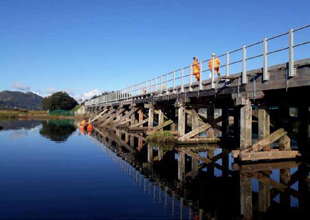
Before the works, downstream face and deck from high mileage.
The structure has 16 spans and 15 trestles which are numbered from low mileage with the Down Side on the Seaward face and the Up Side on the Upstream face. Describing the timber trestles from the bottom up there are five piles per trestle that are embedded in the riverbed. The piles have a lapped splice at lower lever and then extend up to the cross head. The piles are braced by horizontal lower and upper wailings and also diagonal cross braces.

Trestles 7 to 11 in the deeper sections of river have out-riggers and lower wailings for extra stability which connect to additional piles outside of the structure. Each trestle has a cross head which supports the corbels and edge beams on the outside and the main span beams under the waybeams and track. The timbers’ joints are secured together with through bolts and metal straps. On top of the upper edgebeam is a kicker board and a handrail for access to the cess on both sides.
Some of the structures’ timbers were in varying states of decay and the metal straps had severe corrosion as one would expect in a marine estuary environment. Timber decay usually propagates in joint areas particularly just above the water line. The new pile splices were moved to lower positions, either in the riverbed or below water level as this prolongs their life, being subject to one condition rather than wet and dry.
Cass Hayward Consultants had surveyed the structure and produced a list of members for renewal. It also produced a Form A civils proposal and, under Amco’s direction, produced the Form B including temporary works from which timber members could be ordered and the scheme delivered.
The structure was surveyed using pointcloud scanning techniques and a wireframe 3D model extracted from the pointcloud.
From the wireframe 3D model, plans, elevations, cross-sections, and details can be easily produced for drawing production. The drawing set included whole elevations for the bridge and details of each trestle and specifics of metal work straps, joints, and handrails. From these drawings materials could be ordered and work activities planned to include construction sequence animations.
Timber specification

The main structural timbers were specified as Greenheart. Greenheart is a D70 grade timber chosen for its Rot Resistance. Greenheart is rated as a very durable material and is also resistant to most insect attacks. It is also considered to be one of the best-suited woods for use in marine environments and has excellent weathering characteristics.
Workability on site is somewhat difficult on account of its density and interlocking grain, with a moderate to high blunting effect on cutters. It was not uncommon to see sparks flying from the blades of the chainsaws as the members were fashioned on site.
Greenheart density is around 1,010 kg/m3, so some members weighed up to three tonnes. The timber members were shipped in from Guyana during lockdown conditions in early 2021. Steelwork straps and through bolts were replaced with stainless steel.
The existing timber post and metal handrail was completely replaced with an Eziclamp Fibre Reinforced Plastic system. The posts and handrail were bolted to the edgebeams and were lightweight, robust, and aesthetically pleasing.
Other design and construction requirements
Temporary works were required for jacking the deck of the structure to allow members to be replaced. A Mabey jacking system was designed that braced and jacked off the lower wailings through a system of tied props and beams up to the soffit of the deck. All bridge members that were employed in this had to be hardwood as softwood was not deemed competent enough. Exclusion zones were also set out so that RRVs would not compromise structural integrity whilst certain members were removed.

Track levels were surveyed in advance of the jacking, monitored during works, and a track handback engineer was on site to sign the track back into use. Track monitoring was implemented by way of retro-reflective targets attached to the track read by a total station every 24 hours after the work.
Access and environment
The following constraints and site challenges made what was essentially a simple like-for-like member replacement scheme incredibly complex.
» River Glaslyn Estuary Environment - flood plain & tidal waters.
» Sites of special scientific interest (SSSIs), national nature reserves, and conservation areas.
» Working at height around a complex structure.
» Working over, on, and underwater.
» 150mm gas main had to be removed from structure before works commenced.
Fortunately, existing access roads are at either side of the river and structure, from Minffordd on the low mileage and Porthmadog on the high mileage sides – this also included track access points. Unfortunately, the access road to the high mileage was under water for a lot of the time, and the access from the low mileage was under water for some of the time.
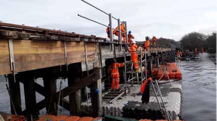
Access to the structure from the water was enabled with the use of scaffold on pontoons, barge platforms and boats and the extensive use of divers.

Access from the railway was by two Road Rail Vehicle 30t Giga Cranes with lifting beams, with material loaded on trailers from Minffordd quarry access.
The site compound welfare facilities and storage were positioned 450 metres East to the Minffordd end of the structure, as a SSSI wood and wetland prevented locating it any closer.
Stakeholder liaison was undertaken in advance of the works with various councils and statutory bodies and permits sought – in particular a Flood Risk Assessment Permit (FRAP) to allow works in the river to commence.
Flooding
With many activities requiring staff to be partially or fully submerged in the water of the river, a greater understanding of the tidal environment was required to safely plan the works.
The tidal range and the flow rates expected vary greatly depending on weather conditions and tidal cycles. Traeth Mawr is a flood plain that was created on building of the Porthmadog Cob and the tidal gate which was further added to protect the harbour and town. The tidal gate is operated by hydrostatic pressure and, as the tide drops, the river water is allowed to flow out at a controlled rate. This however creates a significant tidal range of water height at the viaduct and varying flow rates which get more severe as rain increases.
The river Glaslyn source is on Mount Snowdon and the significant catchment area covers many other mountains and tributaries in the Snowdonia range. To predict the water heights and flow rates, a local consultant was engaged to produce a model and assess the inputs and restrictions that influence the site predicting flood returns of 25-, 50-, and 100-year cycles. A tidal range of approximately 3 metres and maximum average flow rates of 1 metre/s were predicted. Divers can safely work in 2 metres/s and were equipped with flow rate meters. The reality was that flow rates varied over the cross section of the river channel and did exceed the predictions, so work was suspended during these events which were further exacerbated by high winds.
Two teams of divers were employed to work in and under water, 24 hours a day, in shifts. Diving equipment tanks and lines were stored on pontoons and the barge. Divers wearing drysuits and breathing apparatus including helmets were only allowed to work two hours underwater at any time and then would return to the surface to recuperate for two hours. The temperature of the water was around 50C, so divers would get cold quickly even with warm air being pumped into the suits. Divers used specialist underwater tools for cutting and drilling wood and metal. Severe weather conditions events were experienced during the first blockage, and work had to be suspended several times, mainly due to flooding affecting access roads and high winds making it unsafe on the water. High water levels made it difficult to access the structure as navigating below and around it became impossible. Additional diving resource was mobilised to site, but many activities had to be re-planned for follow up blockades.
Construction
Delivery Programme - 24hr Working during Railway Blockade:
» All works originally planned to be completed in February 2021 in a nine-day blockade.
The reality was that another two blockades were required:
» March 2021 - five-day blockade.
» September 2021 - five-day blockade whilst Barmouth works are on – all works complete and handed back to Network Rail.


During the February blockade, work shifts were cancelled several times due to extreme weather events and flooding. The programme of structure element replacement lost all its activity float, and items had to be delayed for later installation. On-site designers had to establish essential and critical works and what items could be delayed. Commissioning the structure and signing back into use at the end of the blockade was challenging as time ran out. Real-time assessments of what work was complete and what work was immediately outstanding and their dependant criticality had to be hastily arranged as the end of the blockade loomed.
Conclusion
The same question asked at both PWI Section presentations was “Why was the scheme delivered in February, when one can expect extreme weather conditions?”. The main driver was that train service patronage would be lower, so inconvenience caused by the blockade would be less disruptive to the travelling public. However, the risk of construction activities being severely delayed and the knock-on effect for delivery of the scheme caused by flooding and high winds could have been factored in a manner which offered greater flexibility and accounted for in the planning with additional programme float. Flood modelling should have been carried out much earlier on when planning the scheme, as access to the structure and construction activities were wholly dependent on this. It should not be underestimated what it is like working on or under the water in the hours of darkness, during lockdown, and in the wind and rain. Amco Giffen and the Network Rail team showed excellent determination, agility, and tenacity by delivering this scheme in difficult conditions.


