Visio 3:1 Uniq - Installationsmanual - UK

Page 1

INSTALLATION GUIDE (UK)

VISIO UNIQ 3:1

PRODUCTION NUMBER

Production number

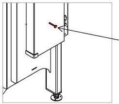
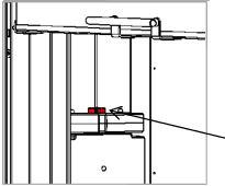
The production number is found in the bottom left corner of the fireplace insert. See drawing. It is also found at the front of the user manual.

Revision:

Date:

1

25-01-2024

EN 2 - EN
We reserve the right to make printing errors.

INSTALLATION GUIDE

INSTALLATION GUIDE

General information

Chimney

TECHNICAL DATA

Specificatios

Dimensional skteches

Information plate

INSTALLATION

Packaging at

Recycling of packaging

Transport security

Air concentrator plate

CHOICE OF MATERIAL FOR INSTALLATION

INSTALLATION DIMENSIONS INSULATED FLUE

Installation dimensions

CONVERT

EN EN - 3
. . . . . . . . . . . . . . . . . . . . . . . . . . . . . . . . . . . . . . . . . . . . . . . . . . . . . . . . . . . .
. . . . . . . . . . . . . . . . . . . . . . . . . . . . . . . . . . . . . . . . . . . . . . . . . . . . . . . . .
. . . . . . . . . . . . . . . . . . . . . . . . . . . . . . . . . . . . . . . . . . . . . . . .
delivery
. . . . . . . . . . . . . . . . . . . . . . . . . . . . . . . . . . . . . . . . . . . . . .
. . . . . . . . . . . . . . . . . . . . . . . . . . . . . . . . . . . . . . . . . . . . . . Set-up insulated flue INSTALLATION DIMENSIONS UN-INSULATED FLUE Installation dimensions . . . . . . . . . . . . . . . . . . . . . . . . . . . . . . . . . . . . . . . . . . . . . . Set-up un-insulated flue . . . . . . . . . . . . . . . . . . . . . . . . . . . . . . . . . . . . . . . . . . . . . HEAT DISTRIBUTOR
TO SELF-CLOSING DOOR BEFORE BUILDING IN THE INSERT CONVERT TO SELF-CLOSING DOOR AFTER BUILDING IN THE INSERT EXTERNAL AIR CONNECTION, AIRSYSTEM DECLARATION OF PERFORMANCE TEST CERTIFICATE SPARE PARTS 4 4 5 6 6 7 8 9 9 9 10 11 12 13 13 14 16 16 17 19 20 21 22 23 24 26

INSTALLATION GUIDE

INSTALLATION GUIDE

Thank you for choosing your new RAIS or ATTIKA product! This installation instructions manual will ensure that your fireplace insert is installed correctly and that it will provide you with comfort and pleasure for many years to come.

GENERAL INFORMATION

It is important to correctly install the fireplace insert out of consideration for both the environment and personal safety.

The installation must comply with all local rules and regulations, including those that refer to national and European standards. A certified chimney sweeper should be contacted before set-up.

No unauthorised alterations may be made to the fireplace insert.

GENERAL INSTALLATION REQUIREMENTS

Before the fireplace insert may be put to use, the set-up must be reported to your local chimney sweeper.

There must be a plentiful supply of fresh air into the room where the insert is placed to ensure good combustion, possibly through an AirSystem connection. Be aware that any mechanical air extraction, for example a cooker hood, can reduce the supply of air. Any air vent must be positioned in a way that ensures the supply of air cannot be blocked.

The air consumption of the fireplace insert is 37,5 m3/h.

The floor structure must be able to support the weight of the fireplace insert and a chimney, if required. If the existing floor structure does not meet this requirement, suitable measures must be taken (e.g. installation of a load distribution plate). If in doubt, contact a building expert.

NOTE!

RAIS/ATTIKA recommends having the insert installed by an authorised technician. Please ask your dealer for further information.

EN 4 - EN

INSTALLATION GUIDE

National and local regulations must be complied with, including the size of the non-flammable plate that must cover the flammable floor in front of the fireplace insert to protect the floor from falling embers.

The fireplace insert must be positioned at a safe distance from flammable material. Due to risk of fire, flammable items (e.g. furniture) may not be positioned closer to the insert than specified in the sections on placement.

When deciding where to install your RAIS/ATTIKA fireplace insert, you should consider being able to heat other rooms in your home to get the most out of your new fireplace insert.

After receiving your fireplace insert, please check it for any defects.

CHIMNEY

As a minimum, the chimney must be constructed of T400-N1-D50050-G100 flue pipe, and be tall enough that the draft conditions are in order, i.e. -12 pascal to -18 pascal. If the recommended chimney draught cannot be achieved, problems of smoke puffing from the door may arise when heating. We recommend adapting the chimney to the flue pipe collar. The collar is 200 mm in diameter.

If the draught is too strong, it is advisable to equip the chimney with a regulating damper. If a regulating damper is fitted, you must ensure that there is a free flow-through area of at least 20 cm² when the regulating damper is closed.

Remember: there must be unobstructed access to the access door on the chimney.

The length of the chimney, calculated from the top of the fireplace insert should not be less than 3 metres and must be at least 80 cm above the roof ridge. If the chimney is placed on the side of the house, the top of the chimney must never be lower than the roof ridge or the roof’s highest point. Note that there are often national and local regulations relating to houses with thatched roofs.

The fireplace insert is suitable for being connected to a shared flue, but we recommend that the feed-ins are positioned to maintain a clearance-level difference of at least 250 mm between them.

EN EN - 5

SPECIFICATIONS

Danish Technological Institute ref.: 300-ELAB-2646-EN

The fireplace insert was tested and approved by:

DTI

Danish Technological Institute

Teknologiparken Kongsvang Allé 29

8000 Aarhus C

Denmark

www.dti.dk

Tel.: +45 7220 2000, Fax: +45 7220 1019

*Not verified by test.

**Max. load

EN 6 - EN
TECHNICAL DATA
VISIO UNIQ 3:1 Nominal output (kW) 11,3 Heating area (m2) 180 Fireplace insert W x D x H (mm) 631 X 1062 X 1637 Combustion chamber W x D x H (mm) 237 X 638 X 234** Min. flue draught (pascal) -12 Weight (kg) min., depending on the model 318 kg Efficiency (%) 76 CO emission attributed to 13% O2 (%) 0,0930 / 1162 mg/Nm³ NOx emission attributed to 13% O2 (mg/Nm³) 76 OGC emission attributed to 13% O2 (mg/Nm³) 74 Particle emission in accordance with NS3058/3059 (g/kg) 6,57 Dust measurement in accordance with DIN + 13% O2 (mg/Nm³) 36 Flue gas flow (g/s) 12,3 Flue gas temperature (°C) 262 Intended flue gas temperature (°C) at flue collar 314 Recommended wood volume (kg) for stoking the fire (Dispersed over three pieces of firewood) 3,0 Intermittent operation Stoking should be done within 52 minutes

INFORMATION PLATE

INFORMATION PLATE

All RAIS/ATTIKA fireplace inserts have a rating plate specifying the distance from the fireplace insert to flammable materials, efficiency, etc. The rating plate is lying unattached in the fireplace insert upon delivery.

23

EN 13240:2001+A1:2004,

EC.NO: 14

Notified Body: 1235

Produced at: RAIS A/S, Industrivej 20, 9900 Frederikshavn, Denmark

Visio Uniq 3:1

AFSTAND TIL BRÆNDBART, BAGVÆG

ABSTAND ZU BRENNBAREN BAUTEILEN, HINTEN

DISTANCE TO COMBUSTIBLE BACK WALL

DIST. ENTRE COMPOSANTS COMBUSTIBLES, ARRIÈRE

AFSTAND TIL BRÆNDBART, SIDEVÆG

ABSTAND ZU BRENNBAREN BAUTEILEN, SEITE

DISTANCE TO COMBUSTIBLE SIDE WALL

DISTANCE ENTRE COMPOSANTS COMBUSTIBLES, COTÉ

AFSTAND TIL BRÆNDBART, MØBLERING

ABSTAND VORNE ZU BRENNBAREN MÖBELN

DISTANCE TO FURNITURE AT THE FRONT

DISTANCE ENTRE COMPOSANTS COMBUSTIBLES, DEVANT

CO EMISSION (REL. 13% O2)

CO EMISSION IN DEN VERBRENNUNGSPRODUKTEN (BEI 13%O2)

EMISSION OF CO IN COMBUSTION PRODUCTS (AT 13%O2)

EMISSION CO DANS LES PRODUITS COMBUSTIBLES (À 13%O2)

STØV / STAUB / DUST / POUSSIÈRES:

DK: 0 mm SE BRUGERVEJLEDNING

DE: 0 mm SIEHE BEDIENUNGSANLEITUNG

UK: 0 mm SEE USER MANUAL

FR: 0 mm CONSULTEZ LE GUIDE DE L’UTILISATEUR

DK: 600 mm SE BRUGERVEJLEDNING

DE: 600 mm SIEHE BEDIENUNGSANLEITUNG

UK: 600 mm SEE USER MANUAL

FR: 600 mm CONSULTEZ LE GUIDE DE L’UTILISATEUR

DK: 800 mm SE BRUGERVEJLEDNING

DE: 800 mm SIEHE BEDIENUNGSANLEITUNG

UK: 800 mm SEE USER MANUAL

FR: 800 mm CONSULTEZ LE GUIDE DE L’UTILISATEUR

≤ 0,12 % / ≤ 1500 mg/Nm³

≤ 40 mg/Nm3

RØGGASTEMPERATUR / ABGASTEMPERATUR / FLUE GAS TEMPERATURE / TEMPÉRATURE DES GAZ DE FUMÉE: 262 °C

NOMINEL EFFEKT / HEIZLEISTUNG / THERMAL OUTPUT / PUISSANCE

CALORIFIQUE: 11,3 kW

DK: Brug kun anbefalede brændsler. Følg instrukserne i brugermanualen. Anordningen er egnet til røggassamleledning og intervalfyring.

DE: Lesen und befolgen Sie die Bedienungsanleitung. Zeitbrandfeuerstätte. Nur empfohlene Brennstoffe einsetzen.

UK: Fuel types (only recommended). Follow the installation and operating instruction manual. Intermittent operation.

FR: Veuillez lire et observer les instructions du mode d’emploi.

Foyer à durèe de combustion limitèe, homologué pour cheminée à connexions multiples. Utiliser seulement les combustibles recommandés.

(Not to be used in a shared flue in UK)

Geeignet für den Anschluss an einen gemeinsamen Schornstein, sofern beide Geräte den gleichen Besitzer haben.

Suitable for connection to a shared flue, on the condition that both devices have the same owner.

DK: BRÆNDE

DE: HOLZ

UK: WOOD

FR: BOIS

Raumheizer für feste Brennstoffe

Appliance fired by wood

Poêle pour combustibles solides

Produced for: ATTIKA FEUER AG, Brunnmatt 16, CH-6330 Cham / RAIS A/S, Industrivej 20, DK-9900 Frederikshavn

EN 8 - EN

INSTALLATION

INSTALLATION

The following section explains how to install the fireplace insert and includes information about packaging, placement distances, etc.

PACKAGING AT DELIVERY

Upon delivery, the fireplace insert is secured to a transport pallet using four transport safety fittings. The safety fittings are attached with screws which must be unscrewed. The safety fittings can then be removed.

RECYCLING OF PACKAGING

The fireplace insert is delivered in recyclable packaging. This packaging must be disposed of in accordance with national regulations relating to the disposal of waste.

NB: DISPOSE OF THE FIREPLACE INSERT WHEN IT

IS WORN OUT.

The glass is not recyclable. The glass must be disposed of along with any residual ceramic or porcelain waste. Heat-resistant glass has a higher melting point, which is why it is not recyclable.

By ensuring heat-resistant glass does not end up alongside recyclable products you are making an important contribution to the environment.

EN EN - 9

TRANSPORT SECURITY

IMPORTANT!

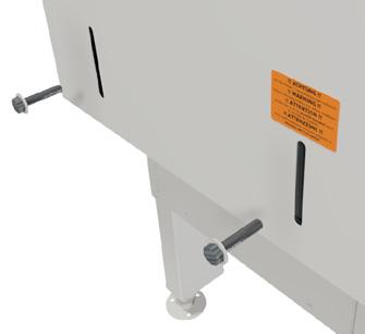
On delivery, the door is locked for transport and must be released before installation. This is done by removing the two transport screws in the counterweights on the back of the oven!

EN 10 - EN
INSTALLATION

INSTALLATION

AIR CONCENTRATOR PLATE

IMPORTANT!

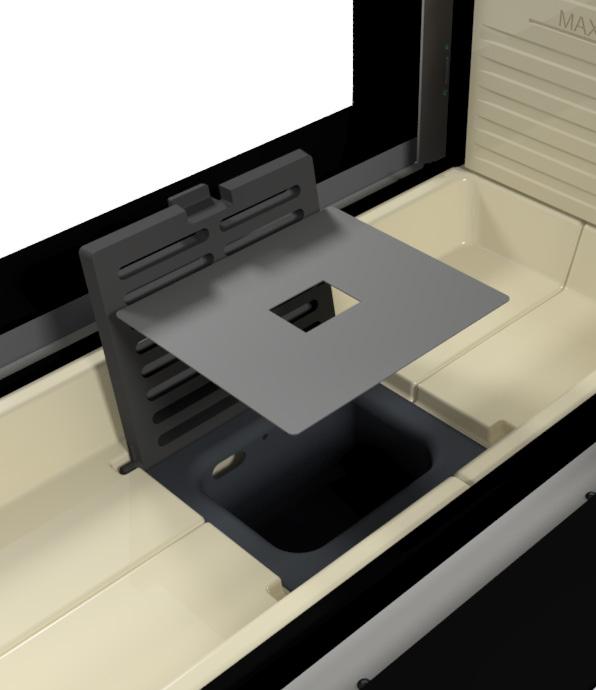
The oven comes with an air concentrator plate that must be removed before use.

The installation of Visio Uniq 3:1 may differ depending on the country in which it is installed. In Norway pursuant to Norway’s open-plan office rules requires the insertion of a mechanical stopper in the flue. See the manual in Norwegian for more information.

EN EN - 11

CHOICE OF MATERIAL FOR INSTALLATION

The material can be panels/brick with an insulation value greater than 0.03 m² x K/W.

The insulation is defined as wall thickness (in metres) divided by the wall’s Lambda value.

Consult your installation technician/chimney inspector.

During testing, the fireplace insert is installed in a cabinet made of nonflammable 50 mm calcium silicate panels (Skamotec 225).

The stove comes with a flue collar that is 200 mm in diameter.

The flue collar can be changed from a top outlet to a rear outlet.

Loosen the clamping strap on the outlet flange and adjust as preferred.

The fireplace insert must be placed on heat-resistant material.

See the following pages for installation dimensions and placement distances.

VIGTIGT!

As a minimum, the chimney must be constructed of T400-N1-D-50050-G100 flue pipe.

EN 12 - EN

INSTALLATION DIMENSIONS INSULATED FLUE

INSTALLATION DIMENSIONS

Applies to installation into non-flammable panels. Minimum cavity dimensions (H x W x D): . 560 x 631 x 887 mm

A fireplace insert must never be tightly inserted into a cavity, as steel expands when heated.

There must be a minimum convection air intake of 500 cm² underneath the stove and 700 cm² above it. The minimum convection-air areas above and below the stove can be distributed over several holes.

Distance Dimensions mm

Distance from convection grate to flammable ceiling 380

Distance from lower door edge to flammable floor 410

Convection air discharge area = Min. 700 cm2

Convection air air intake area = Min. 500 cm2

Change o rd Drawing chan g D M Y 27-1 0-2023 631 887 5 6 0 EN EN - 13

SET-UP INSULATED FLUE

A non-combustible plate must be installed directly above the convection air draft.

ATTENTION!

The insulated chimney must extend all the way down to the flue outlet adapter.

EN 14 - EN

INSTALLATION DIMENSIONS UN-INSULATED FLUE

INSTALLATION DIMENSIONS:

Applies to installation into non-flammable panels. Minimum cavity dimensions (H x W x D): . 560 x 631 x 887 mm mm

A fireplace insert must never be tightly inserted into a cavity, as steel expands when heated.

There must be a minimum convection air intake of 500 cm² underneath the stove and 700 cm² above it. The minimum convection-air areas above and below the stove can be distributed over several holes.

Distance Dimensions mm

Distance from convection grate to flammable ceiling 380

Distance from lower door edge to flammable floor 410

chan ge: C D M Y 27-1 0-2023 631 887 5 6 0 EN 16 - EN
Change o rde Drawing
Convection air discharge area = Min. 700 cm2
Convection air air intake area = Min. 500 cm2

SET-UP UN-INSULATED FLUE

A non-combustible plate must be installed directly above the convection air draft.

ATTENTION!

The insulated chimney must pass through the non-combustible plate.

EN EN - 17

HEAT DISTRIBUTOR

HEAT DISTRIBUTOR

By installing a heat distributor unit above the fireplace insert, heat can be ‘transported’ to other rooms.

EN EN - 19
COLD AIR WARM AIR

CONVERT TO SELF-CLOSING DOOR BEFORE BUILDING IN THE INSERT

Convert the door to self-closure by removing some of the door’s counterweights. There are counterweights on both sides.

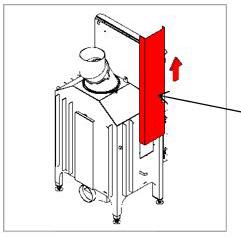
1. Remove the transport safety fittings and retainer screws for the counterweight cover

Transport safety fitting.

2. Remove the counterweight cover by pulling it up.

Counterweight cover.

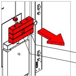
3. Loosen the locking ring (2.5 mm hex key). Remove the number of counterweights that allow the door to close slowly and at a constant speed. Double-check the function.

Counterweights

Locking ring

4. Tighten the locking ring (2.5 mm hex key)

Locking ring

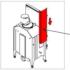
5. Attach the counterweight cover and the retainer screw(s).

Counterweight cover.

EN 20 - EN

CONVERT TO SELF-CLOSING DOOR AFTER BUILDING IN THE INSERT

Convert the door to self-closure by removing some of the door’s counterweights. There are counterweights on both sides.

1. Remove the side Skamol panel.

2. Remove the access panel.

Access panel.

3. Loosen the locking ring (2.5 mm hex key). Remove the number of counterweights that allow the door to close slowly and at a constant speed. Double-check the function.

Locking ring. Counterweights.

4. Tighten the locking ring (2.5 mm hex key).

Locking ring.

5. Re-attach the access panel and side Skamol panel.

Access panel.

EN EN - 21

EXTERNAL AIR CONNECTION, AIRSYSTEM

EXTERNAL AIR CONNECTION, AIRSYSTEM

All RAIS/ATTIKA fireplace inserts can have an external air connection for combustion. We call this external air supply AirSystem. The system can be connected to the underside of the fireplace insert.

EN 22 - EN
150 mm flexi hose (metal)

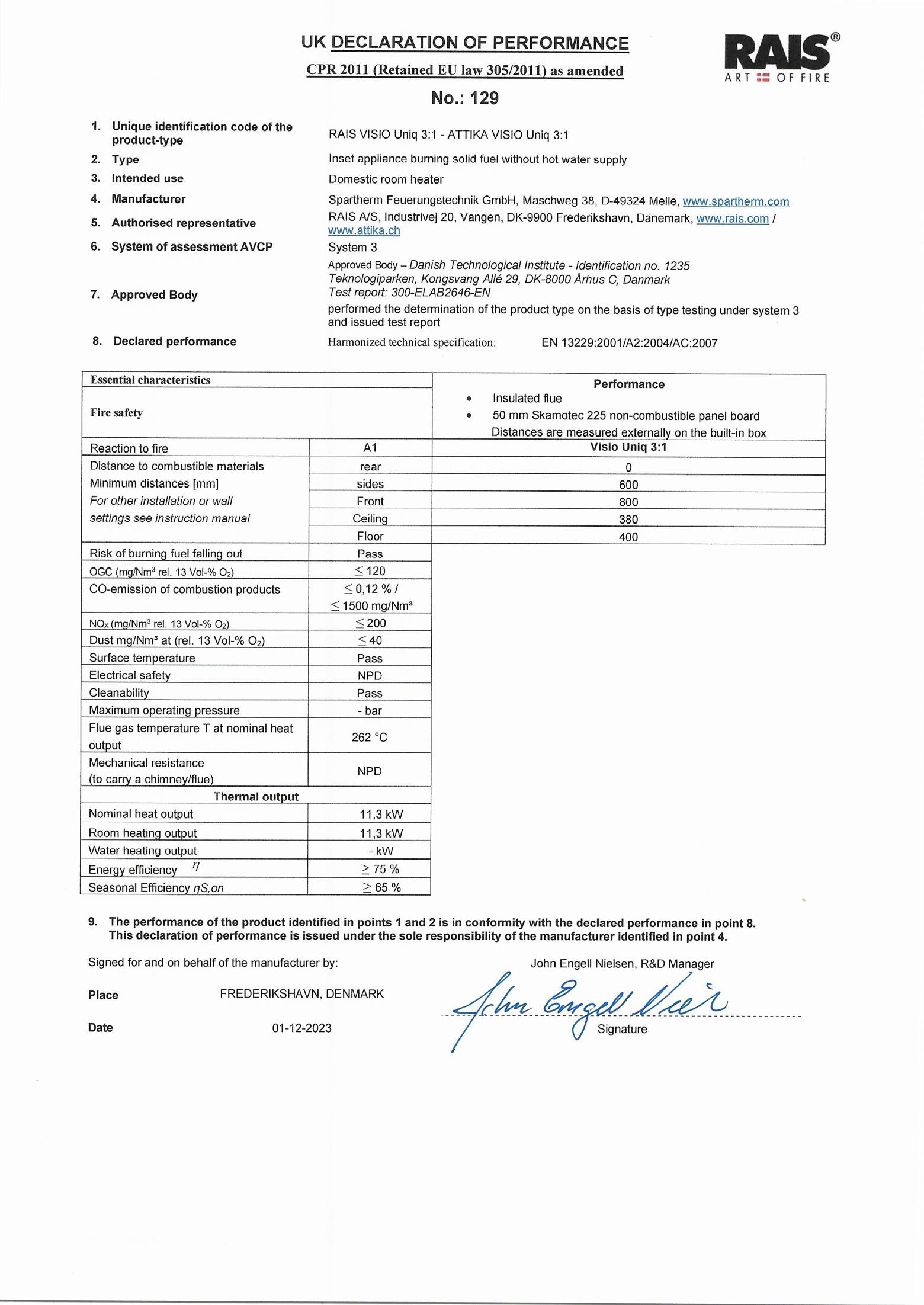
DECLARATION OF PERFORMANCE

EN EN - 23

TEST CERTIFICATE

EU DECLARATION OF CONFORMITY

Company name: Rais A/S

Postal address: Industrivej 20

Postcode: 9900

City: Frederikshavn, Denmark

Telephone number: +45 98 47 90 33

E-Mail address: kundeservice@rais.dk

Declare that the DoC is issued under our sole responsibility and belongs to the foliowing produet:

Rais project number: 129

Models: RAIS VISIO Uniq 3:1

ATTIKA VISIO Uniq 3:1

I Last two figures, the year, where the CE-Label was put on the stove I 23

Object of the declaration:

Room heater

A R T :: 0 F F I R E
RAIS®
Type lnset aooliance burninq solid fuel without hot water supply Serial number: All staves have a unique serial number that is affixed to the stove. The location of the sticker is indicated in the user
and is recorded in the
serial number
manual
Rais
database.
EN 24 - EN

TEST CERTIFICATE

The object of the declaration described above is in conformity with the relevant top-level directives and regulations

� DIR 2009/125/EC 21/10/2009 Energy Related Produets Direetive (eeodesign)

� REG (EU) 305/2011 9/3/2011 Construetion Produets Regulation (CPR) REG (EU) 2017/1369 4/7/2017 Energy Labelling Regulation

Implementation measures incl regulations and delegated acts

� (EU) 2015/1186 (EL) 24/4/2015 Energy labelling delegated aet on Room heaters

� (EU) 2015/1185 (ED) 24/4/2015 Eeodesign regulation on Room heaters 2017/C 076/02 10/3/2017 COM Transitional methods OJ EU C76 Vol 60

Harmonized standards, other standards, and technical specifications

� EN 13229:2001 13/6/2001 lnset applianees ineluding open fires fired by solid fuels

� EN 1 3229/A1 :2003 02/04/2003 lnset applianees ineluding open fires fired by solid fuels

� EN 13229/A2:2204 15/09/2004 lnset applianees ineluding open fires fired by solid fuels

� CENfTS 15883 8/9/2009 Emission measurement from 2009

IZI EN 16510-1:2018 31/7/2018 Emission measurement methods 2018 onwards

Notified body 4 digit notified body number: I Danish Teehnological lnstitute I 1235

Additional information:

Further information on declared fire safety performance & emissions are available in the Declaration of performance. (DOP)

PLAGE: FREDERIKSHAVN, DENMARK

Date: 26-10-2023

John Engell Nielsen

R&D / Quality Manager

Installation approved by.

Date:

Signature

A R T :: 0 F F R E
EN EN - 25

SPARE PARTS LIST

SPARE PARTS VISIO UNIQ 3:1

If spare parts other than those recommended by RAIS are used, the warranty is void. All replaceable parts can be purchased as spare parts from your RAIS dealer.

See spare parts drawing.

POS. DESCRIPTION

1 Handle for damper - complete

2 Damper - complete

3 Door handles

4 Glass moldings left door - Painted

5 Glass strips left door - Stainless

6 Glass moldings right door - Painted

7 Glass strips right door - Stainless

8 Glass strips top front door - Painted

9 Glass strips top front door - Rust-free

10

EN 26 - EN
Glass strips bottom front door - Painted
Glass strips bottom front door - Stainless 12 Door glass front 13 Door glass left 14 Door glass right 15 Chamotte (refractory stones - Bottom) 16 Wall Skamol
11

RAIS A/S Industrivej 20

DK-9900 Frederikshavn

Denmark

www.rais.com

ATTIKA FEUER AG

Brunnmatt 16

CH-6330 Cham

Switzerland

www.attika.ch

Turn static files into dynamic content formats.

Create a flipbook
Issuu converts static files into: digital portfolios, online yearbooks, online catalogs, digital photo albums and more. Sign up and create your flipbook.