TECHNICAL DATA LEAFLET
GAS
GAS/2 Series Two Stage Gas Burners
GAS 3/2
80/130
÷
350
kW
GAS 4/2
120/180
÷
470
kW
GAS 5/2
155/320
÷
660
kW
GAS 6/2
300/520
÷
1050
kW
GAS 7/2
400/800
÷
1760
kW
GAS 9/2
1000/1750
÷
3200
kW
www.riello.com
Two Stage Gas Burners
Gas Series
The GAS/2 series of burners covers a firing range from 130 to 3200 kW and they have been designed for use in civil installations of average dimensions, like building areas and large apartment groups or for use in industrial applications, like small or medium plants. Operation is two stage; the combustion head, that can be set on the basis of required output, allows optimal performance ensuring good combustion and reducing fuel consumption. The main feature of these burners is their reliability due to a simple and strong construction, which permits operation without particular maintenance intervention. Simplified maintenance is achieved by the slide bar system, which allows easy access to all of the essential components of the combustion head. All electrical components are easily accessible only by dismounting a protection panel, thus guaranteeing a quick and simple intervention on components.
2
Technical Data MODEL
GAS 3/2
GAS 4/2
GAS 5/2
Burner operation mode Modulation ratio at max. output Servomotor
GAS 6/2
2÷1
Heat output Working temperature
GAS 9/2 3÷1
type run time
GAS 7/2
Two stage LKS210
s
5
kW
80/130÷350
120/180÷470
155/320÷660
300/520÷1050
400/800÷1760 1000/1750÷3200
Mcal/h
69/112÷301
104/155÷404
133/275÷568
258/447÷903
344/668÷1514
860/1500÷2752
30/52÷105
40/80÷176
100/175÷320
35/60.5÷122
46.5/93÷205
116/203÷372
11.5/20÷41
15.5/31÷68
39/68÷124
°C min./max.
0/40
FUEL/AIR DATA kWh/Nm3
10
G20 density gas
kg/Nm3
0,71
G20 gas delivery
Nm3/h
Net calorific value G20 gas
Net calorific value G25 gas G25 density gas
kg/Nm3
G25 delivery gas
Nm3/h
Net calorific value LPG gas LPG gas density
kg/Nm3 Nm3/h
Air temperature
12/18÷47
15.5/32÷66 8.6 0.78
9/15÷41
14/21÷55
18/37÷77 25.8
kWh/Nm3
LPG gas delivery Fan
8/13÷35
kWh/Nm3
2.02 3/5÷13.5
5/7÷18
6/12÷25.5
type
Centrifugal with forward curve blades
Max. °C
60
ELECTRICAL DATA Electrical supply
Ph/Hz/V
Auxiliary electrical supply
Ph/Hz/V
Control box
3N/50/400~(±10%) (star) 3/50/230~(±10%) (delta)
1/50/230~(±10%)
1/50/230~(±10%)
type
RMG
Total electrical power
kW
0.4
0.54
0.85
1,7
3.4
9
Auxiliary electrical power
kW
0.15
0.17
0.1
0.2
0.4
1.5
Protection level
IP
Motor electrical power
kW
0.25
0.37
0.75
1.5
3
7.5
A
1.8
2.9
2.85÷1.65
5.9÷3.4
10.9÷6.3
26÷15
Motor start current
A
4.8
9.5
10÷6
22.5÷13
Motor protection level
IP
54
55
V1 - V2
230V - 1x8 kV
230V - 1x8 kV
1.8A - 20 mA
1.8A - 30 mA
Rated motor current
Ignition transformer
40
I1 - I2
Operation
Intermittent (at least one stop every 24 h)
EMISSIONS Sound pressure Sound power
dBA
75
78
83
W
84
87
89.4
--
CO Emission
mg/kWh
< 100
< 10
NOx Emission
mg/kWh
< 170
< 150
APPROVAL Directive Conforming to Certification
2006/42/EC - 2009/142/EC - 2014/30/UE - 2014/35/UE EN 676 CE 0085AQ0707
--
Reference conditions: Temperature: 20°C - Pressure: 1013,5 mbar - Altitude: 0 m a.s.l. - Noise measured at a distance of 1 meter. Since the Company is constantly engaged in the production improvement, the aesthetic and dimensional features, the technical data, the equipment and the accessories can be changed. This document contains confidential and proprietary information of RIELLO S.p.A. Unless authorised, this information shall not be divulged, nor duplicated in whole or in part.
3
Two Stage Gas Burners
Gas Series
Firing Rates 18 GAS 9/2 16 14 GAS 7/2 12 GAS 6/2
10
GAS 4/2 GAS 5/2
8
GAS 3/2 6
hPa (mbar)
4 2 0 0 0
200 200
400 400
600 600
800
800
1000
1000
1200
1200 1400
Useful firing rate for choosing the burner Test conditions conforming to EN 676: Temperature: 20°C Pressure: 1013,5 mbar Altitude: 0 m a.s.l.
4
1400
1600
1600 1800
1800
2000
2000 2200
2400
2200
2400
2600
2600 2800 3000
2800 Mcal/h 3200
kW
Fuel Supply GAS TRAIN DESIGNATION
Series:
MB CB Size:
405
407
Operation:
410
/1 /2
412
415
512
-
420 1200 520
CT CQ
Joint type:
R F
threaded joint standard flange ISO T SD SM
Terminals - Terminal strip Domestic plug Medium voltage plug
Standard output pressure range:
Valve control:
/2
CT
R
50125 50150
0 leak detection control device installed on the gas train equipped with pressure switch for leak detection control
Electrical connection:
420
3100 5000 5080 50100
1st stage mode opening 2nd stage mode opening
Leak detection control:
MB
1900 5065
525
T
2
0 2 3 4 5 6 8 15
without pressure governor with governor and air/gas proportional pressure with governor and output pressure up to 20 mbar with governor and output pressure up to 30 mbar with governor and output pressure up to 40 mbar with governor and output pressure up to 50 mbar with governor and output pressure up to 60 mbar with governor and output pressure up to 80 mbar with governor and output pressure up to 150 mbar 0 2
shared separate
0
BASIC DESIGNATION EXTENDED DESIGNATION
5
Two Stage Gas Burners
Gas Series
GAS TRAINS Fuel can be supplied either from the right or left hand sides. The gas train can be selected to best fit system requirements depending on the fuel output and pressure in the supply line. The gas train can be “Multibloc “ type (containing the main components in a single unit) or “Composed” type (assembly of the single components).
Example of the gas train connection flange of GAS/2 burners.
MULTIBLOC GAS TRAIN WITHOUT SEAL CONTROL
11 4
P1
MULTIBLOC
7
10
13
9
8
P2
6
5
3
P3
L
2
1
L1
MULTIBLOC GAS TRAIN WITH SEAL CONTROL
1
Gas input pipework
2
Manual valve
3
Anti-vibration joint
4
Pressure gauge with pushbutton cock
5
Filter
6
Pressure regulator (vertical)
7
Minimum gas pressure switch
8
VS safety solenoid (vertical)
9
10
VR regulation solenoid (vertical) Two settings: - firing output (rapid opening) - maximum output (slow opening) Gasket and flange supplied with the burner
11
Burner
12
13
Seal control mechanism for valves 8-9. According to standard EN 676, the seal control is compulsory for burners with maximum output above 1200 kW. Gas train-burner adapter
P1
Combustion head pressure
11 4
P1
MULTIBLOC
7
10
P2 Pressure downstream from the regulator
13
9
12
8
P2
6
5
P3
3
L
2
P3 Pressure upstream from the filter
1
L
L1
Gas train supplied separately, with the code given in the table Installer’s responsibility
L1
COMPOSED GAS TRAIN WITHOUT SEAL CONTROL
COMPOSED GAS TRAIN WITH SEAL CONTROL
11
11 4 P1
7
10
13
9
8
P2
L
6
4
P1
7
10
6
5
P3
3
2
L1
1
13
9
12
8
P2
L
6
5
P3
3
2
L1
1
Y Øi
Z
Øo Øi
Øo
Y
Z X
X
Example of gas train “COMPOSED” type without seal control
Example of gas train “MULTIBLOC” type without seal control
Gas trains are approved by standard EN 676 together with the burner. The overall dimensions of the gas train depends on how they are constructed. The following table shows the maximum dimensions of the gas trains that can be fitted to the burners of GAS series, intake and outlet diameters and seal control if fitted. Please note that the seal control can be installed as an accessory, if not already installed on the gas train. The maximum gas pressure of gas train “Multibloc” type is 300 mbar, and that one of gas train “Composed” type is 500 mbar. GAS TRAIN MODEL MB 405/2 - RSD 20 MB 407/2 - RSD 20 MB 407/2 - RT 20 MB 410/2 - RSD 20 MB 410/2 - RT 20 MB 412/2 - RT 20 MB 415/2 - RT 20 MB 420/2 - RT 20 MB 420/2 CT RT 20
GAS TRAIN MODEL CB 512/2 - RT 32 CB 512/2 CT RT 32 CB 520/2 - RT 32 CB 520/2 CT RT 32 CB 5065/2 - FT 32 CB 5065/2 CT FT 32 CB 5080/2 - FT 32 CB 5080/2 CT FT 32
CODE
Ø in
Ø out
X mm
Y mm
Z mm
3970084 3970537 3970556 3970534 3970557 3970152 3970183 3970184 3970185
Rp ¾” Rp ¾” Rp ¾” Rp ¾” Rp ¾” Rp 1” ½ Rp 1” ½ Rp 2” Rp 2”
Rp ¾” Rp ¾” Rp ¾” Rp ¾” Rp ¾” Rp 1” ½ Rp 1” ½ Rp 2” Rp 2”
371 371 371 405 405 433 523 523 523
186 196 196 221 221 217 350 410 410
92 92 92 116 116 116 100 100 227
CODE
Ø in
Ø out
X mm
Y mm
Z mm
3970153 20045590 3970154 20045591 3970155 3970167 3970156 3970168
Rp 1” ½ Rp 1” ½ Rp 2” Rp 2” DN 65 DN 65 DN 80 DN 80
Rp 1” ½ Rp 1” ½ Rp 2” Rp 2” DN 65 DN 65 DN 80 DN 80
1013 891 1150 986 1331 1331 934 1770
345 261 350 328 405 405 416 405
195 245 250 255 285 355 285 385
7
Two Stage Gas Burners
Gas Series
Pressure Drop Diagram The diagrams indicate the minimum pressure drop of the burners with the various gas trains that can be matched with them; at the value of these pressure drop add the combustion chamber pressure. The value thus calculated represents the minimum required input pressure to the gas train.
GAS 3/2 (NATURAL GAS) G20
G25 110
100
100
90
MB 405 2
60
MB 407 2
50
p mbar
p mbar
MB 407 2
80
70
40
MB 412 2 MB MB 415 420 22
20 10 130
200
250
300
60 50
MB 410 2
30
MB 412 2
20
MB 415 2 MB 420 2
10
350
150
70
40
MB 410 2
30
0
MB 405 2
90
80
0
kW
130
350
150
200
250
300
kW
GAS 3/2 (NATURAL GAS) G20
G25
20
30 CB 512 2
CB 512 2
25
15
10
CB 520 2
20 p mbar
p mbar
CB 520 2
15
10 5 5
0
130
350
150
200
250
300
kW
Combustion head + gas butterfly valve + gas train Combustion head + gas butterfly valve 8
0
130
350
150
200
250
300
kW
GAS 4/2 (NATURAL GAS) G20
G25 100
100
90
90
MB 407 2
80
80
70 MB 405 2
60 50
MB 410 2
40 30
p mbar
p mbar
70
180
200
50
300
350
400
450
MB 412 2 MB 415 2 MB 420 2
20 10
470
250
MB 407 2
30
MB 415 2 MB 420 2
10
MB 410 2
60
40
MB 412 2
20
0
MB 405 2
0
kW
180
200
470
250
300
350
400
450
kW
GAS 4/2 (NATURAL GAS) G20
G25
35
20
30
CB 512 2
CB 512 2 25
CB 520 2 CB 5065 2
10
p mbar
p mbar
15 CB 520 2
20
CB 5065 2
15 10
5 5 0
180
200
470
250
300
350
400
450
kW
0
180
200
470
250
300
350
400
450
kW
Combustion head + gas butterfly valve + gas train Combustion head + gas butterfly valve 9
Two Stage Gas Burners
Gas Series
GAS 5/2 (NATURAL GAS) G25 60 55 MB 410 2
MB 412 2
50
MB 407 2
45 40 p mbar
p mbar
G20 85 80 75 70 65 60 55 50 45 40 35 30 25 20 15 10 5 0
MB 412 2
35 30
MB 415 2
25
MB 420 2
20 MB 415 2 MB 420 2
15 10 5
320
660
400
500
600
0
kW
320
660
400
500
600
kW
GAS 5/2 (NATURAL GAS) G20
G25
50
30
45 CB 512 2
CB 512 2
40
25 20 CB 520 2 15 CB 5065 2 10
p mbar
p mbar
35 30 CB 520 2
25 20
CB 5065 2 CB 5080 2
15 10
5 5 0
320
660
400
500
600
kW
Combustion head + gas butterfly valve + gas train Combustion head + gas butterfly valve 10
0
320
660
400
500
600
kW
GAS 6/2 (NATURAL GAS) G25 55 MB 410 2
50 MB 412 2
MB 415 2 MB 420 2
45 40
MB 415 2 MB 420 2
p mbar
p mbar
G20 85 80 75 70 65 60 55 50 45 40 35 30 25 20 15 10 5 0
35 30 25 20 15 10 5
500
1050
600
700
800
900 1000
0
kW
500
1050
600
700
800
900 1000
kW
GAS 6/2 (NATURAL GAS) G20
G25
70 100
65 60
90
CB 512 2
55
80
50
70
40 35
CB 520 2
30
p mbar
p mbar
45
60 50
CB 520 2
40
25 20
CB 5065 2 CB 5080 2
15 10
30
CB 5065 2 CB 5080 2
20 10
5 0
CB 512 2
500
1050
600
700
800
900 1000
kW
0
500
1050
600
700
800
900 1000
kW
Combustion head + gas butterfly valve + gas train Combustion head + gas butterfly valve 11
Two Stage Gas Burners
Gas Series
GAS 7/2 (NATURAL GAS) G25 110 MB 412 2
MB 415 2
100
MB 420 2
90
MB 415 2 MB 412 2
MB 420 2
80 p mbar
p mbar
G20 80 75 70 65 60 55 50 45 40 35 30 25 20 15 10 5 0
70 60 50 40 30 20 10
800
1750
1000
1250
1500
0
kW
800
1750
1000
1250
1500
kW
GAS 7/2 (NATURAL GAS)
240 220
CB 512 2
CB 512 2
200 180
CB 520 2
160 140 120 CB 520 2
100 80 60
CB 5065 2 CB 5080 2 800
1750
1000
1250
1500
kW
Combustion head + gas butterfly valve + gas train Combustion head + gas butterfly valve 12
G25 260
p mbar
p mbar
G20 180 170 160 150 140 130 120 110 100 90 80 70 60 50 40 30 20 10 0
CB 5065 2 CB 5080 2
40 20 0
800
1750
1000
1250
1500
kW
460 440 420 400 380 360 340 320 300 280 260 240 220 200 180 160 140 120 100 80 60 40 20 0
G20
G25 100
CB 512 2
CB 5065 2
90 80 70 p mbar
p mbar
GAS 9/2 (NATURAL GAS)
CB 520 2
60
CB 5080 2
50 40 30
CB 5065 2 CB 5080 2 1700
3100
1750 2000 2250 2500 2750 3000
kW
20 10 0
1700
3100
1750 2000 2250 2500 2750 3000
kW
Combustion head + gas butterfly valve + gas train Combustion head + gas butterfly valve 13
Two Stage Gas Burners
Gas Series
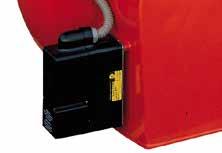
Ventilation The ventilation circuit of GAS/2 burners is inserted in a extremely compact structure and it is provided with a forward blades centrifugal fan, which guarantees high pressure levels at the required air deliveries and permits installation flexibility. A servomotor adjust the air damper in relation to the fuel burnt. When the burner is not operating the servomotor closes completely the air damper to reduce heat dispersion from the boiler. A minimum air pressure switch stops the burner when there is an insufficient quantity of air at the combustion head. Example of servomotor for air damper adjusting on GAS/2 series of burners
Combustion Head Different combustion head length can be selected for the various models of GAS/2 series of burners. The choice depends on the thickness of the front panel and type of boiler. Correct head penetration into the combustion chamber depends on the type of heat generator. These burners are equipped with adjustable combustion head. This enables optimum combustion performance throughout the working field, ensuring peak combustion efficiency thus saving on fuel consumption. The following diagram shows the flame dimensions in relation to the burner output. The lengths and diameter shown in the diagram below should be employed for a preliminary check: if combustion chamber dimensions are different from the values in the diagram, further tests need to be done.
Example of a GAS/2 burner combustion head
DIMENSIONS OF THE FLAME 4
L
2
D max D min
1
0
1
0 1
2
3 4 Burner output (MW)
L
1,5
0,5
0
14
min
Flame diameter (m)
Flame lenght (m)
3
D
2
x
a Lm
Example: Burner thermal output = 2000 kW; L flame (m) = 2.7 m (medium value); D flame (m) = 0.8 m (medium value)
Operation BURNER OPERATION MODE On “two stage” operation, the burner gradually adapts the output to the requested level, by varying between two pre-set levels.
Controlled variable
TWO STAGE OPERATION °C bar
Time
All GAS/2 series burners are fitted with a new microprocessor control panel for the supervision during intermittent operation. For helping the commissioning and maintenance work, there are two main elements:
Output
MAX
MIN
Time
The lock-out reset button is the central operating element for resetting the burner control and for activating / deactivating the diagnostic functions.
The multi-color LED is the central indication element for visual diagnosis and interface diagnosis.
Both elements are located under the transparent cover of lock-out reset button, as showed below.
There are two diagnostic choices, for indication of operation and diagnosis of fault cause: - visual diagnosis:
- interface diagnosis: COMPUTER INTERFACE ADAPTER
By the interface adapter and a PC with dedicated software or by a predisposed flue gas analyzer (see paragraph accessories).
or
FLUE GAS ANALYSER
15
Two Stage Gas Burners
Gas Series
Indication of operation: In normal operation, the various status are indicated in the form of colour codes according to the table below. The interface diagnosis (with adapter) can be activated by pressing the lock-out button for > 3 seconds.
Operation status
Color code table Color code table
Stand-by Pre-purging Ignition phase Flame OK Poor flame Undervoltage, built-in fuse Fault, alarm Extraneous light LED off
Diagnosis of fault causes: After lock-out has occurred, the red signal lamp is steady on. In this status, the visual fault diagnosis according to the error code table can be activated by pressing the lock-out reset button for > 3 seconds. The interface diagnosis (with adapter) can be activated by pressing again the lock-out button for > 3 seconds. The blinkers of red LED are a signal with this sequence: (e.g. signal with n° 3 blinks â&#x20AC;&#x201C; faulty air pressure monitor) LED off 3 sec.
3 sec.
3 sec.
Error code table Blink code 2 blinks
3 blinks
4 blinks
7 blinks
10 blinks
16
Possible cause of fault No flame at the end of safety time: - faulty or soiled fuel valves - faulty or soiled flame detector - poor adjustment of burner, no fuel - faulty ignition equipment Faulty air pressure monitor
Extraneous light or simulation of flame on burner start up Loss of flame during operation : - faulty or soiled fuel valves - faulty or soiled flame detector - poor adjustment of burner Wiring error or internal fault
START UP CYCLE GAS 3/2 - 4/2 - 5/2 - 6/2 - 7/2
TL TR M
A’
B’
A’
B’
2 42
1°
44
42
2°
0 s The burner begins the firing cycle. 2 s The motor starts: pre-purge phase. 42 s Ignition electrode sparks; safety valve VS and the 1st stage VR1 of the adjustment valve VR open. 45 s Lock out signal is activated if flame is not revealed by the flame detector. 52 s Output can be increased by second stage valve VR2 and air damper opening; the start up cycle is concluded.
52 2°
52
1°
2
0 2°
52
1°
42
0
45 0
time (s)
GAS 9/2
TL TR M
A’
B’
A’
B’
2 92
1°
94
92
2°
0 s The burner begins the firing cycle. 2 s The motor starts: pre-purge phase. 92 s Ignition electrode sparks; safety valve VS and the 1st stage VR1 of the adjustment valve VR open. 55 s Lock out signal is activated if flame is not revealed by the flame detector. 102 s Output can be increased by second stage valve VR2 and air damper opening; the start up cycle is concluded.
102 2°
102
1°
2
0 2°
102
1°
92
0
95 0
time (s)
17
Two Stage Gas Burners
Gas Series
Emissions The emission data has been measured in the various models at maximum output, according to EN 676 standard.
NO2 EMISSIONS 160 140
mg/kWh
120 100 80 60 40 20
GAS 3/2
GAS 4/2
GAS 5/2
GAS 6/2
GAS 7/2
GAS 9/2
GAS 7/2
GAS 9/2
0
CO EMISSIONS (gas G20) 50 45 40
mg/kWh
35 30 25 20 15 10 5
GAS 3/2
GAS 4/2
GAS 5/2
GAS 6/2
0
NOISE EMISSIONS 100 90 80 70
dB(A)
60 50 40 30 20 10 0
18
GAS 3/2
GAS 4/2
GAS 5/2
GAS 6/2
GAS 7/2
GAS 9/2
Overall Dimensions (mm) BURNERS GAS 3/2 - 4/2 - 5/2 - 6/2 - 7/2
GAS 9/2
MODEL
A
B
C
D
E
F - F(1)
H
I
M
N
O
V
GAS 3/2
410
205
205
397
610
185 - 320
140
292
1” ½
97
775
165
GAS 4/2
410
205
205
397
610
187 - 320
150
292
1” ½
97
775
165
GAS 5/2
431
226
205
437
645
207 - 365
155
332
1” ½
97
810
165
GAS 6/2
463
258
205
485
770
227 - 360
175
370
2”
131
966
195
GAS 7/2
606
358
248
590
920
240 - 400
220
445
2”
140
1142
245
GAS 9/2
780
445
335
680
1200
444 - 574
295
495
2”
168
1627
210
BURNER - BOILER MOUNTING FLANGE MODEL
D1
D2
Ø
GAS 3/2
155
226
M10
GAS 4/2
165
226
M10
GAS 5/2
165
226
M10
GAS 6/2
185
276
M12
GAS 7/2
230
325
M12
GAS 9/2
300
368
M18
Y
Z
kg
PACKAGING MODEL Z
X - X(1)
Y
X - X(1)
GAS 3/2
850
545
473
34
GAS 4/2
850
545
473
40
GAS 5/2
895
543
520
43
GAS 6/2
1045
543
555
60
GAS 7/2
1400
850
650
98
GAS 9/2
1870
920
910
240 19
Two Stage Gas Burners
Gas Series
Installation Description Installation, start up and maintenance must be carried out by qualified and skilled personnel. All operations must be performed in accordance with the technical handbook supplied with the burner.
BURNER SETTING •
All the burners have slide bars, for easier installation and maintenance.
•
After drilling the boilerplate, using the supplied gasket as a template, dismantle the blast tube from the burner and fix it to the boiler.
•
Adjust the combustion head.
•
Fit the gas train, choosing this on the basis of the maximum output of the boiler and considering the enclosed diagrams.
•
Refit the burner casing to the slide bars.
•
Close the burner, sliding it up to the flange.
ELECTRICAL CONNECTIONS AND START UP •
Make the electrical connections to the boiler following the wiring diagrams included in the instruction handbook.
•
Turn the motor to check rotation direction (if it is a three-phase motor).
•
Perform a first ignition calibration on the gas train.
•
On start up, check: - Gas pressure at the combustion head (to max. and min. output) - Combustion quality, in terms of unburned substances and excess air.
20
Burner Accessories Extended head kit “Standard head” burners can be transformed into “extended head” versions, by using the special kit. The KITS available for the various burners, giving the original and the extended lengths, are listed below. MODEL GAS 3/2
Standard head length (mm) 185
Extended head length (mm) 320
3000605
Kit code
GAS 4/2
187
320
3000606
GAS 5/2
207
365
3000607
GAS 6/2
227
360
3000608
GAS 7/2
240
400
3000678
Spacer kit If burner head penetration into the combustion chamber needs reducing, varying thickness spacers are available, as given in the following table. Spacer thickness S (mm) 142
3000755
GAS 7/2
102
3000722
GAS 9/2
130
3000723
MODEL GAS 3/2 - 4/2 - 5/2 - 6/2
Kit code
Continuous ventilation kit If the burner requires continuous ventilation in the stages without flame, a special kit is available as given in the following table. MODEL
Kit code
GAS 3/2 - 4/2 - 5/2 - 6/2 - 7/2 - 9/2
3010030
Post-ventilation kit To prolong ventilation for approximately 5 seconds after opening of thermostats chain, a special kit is available. MODEL
Kit code
GAS 3/2 - 4/2 - 5/2 - 6/2 - 7/2 - 9/2
3010004
PC interface kit To connect the flame control panel to a personal computer for the transmission of operation, fault signals and detailed service information, an interface adapter with PC software are available. MODEL
Kit code
GAS 3/2 - 4/2 - 5/2 - 6/2 - 7/2 - 9/2
3002719
21
Two Stage Gas Burners
Gas Series
Sound proofing box D
E A B
C
If noise emission needs reducing even further, sound-proofing boxes are available. In case of generator heights, where a lower dimension â&#x20AC;&#x153;Bâ&#x20AC;? is required, ask for the Box Support Kit code 20065135. The useful dimensions are 40 mm less than the total dimensions indicated in the table (A, D, E). Not suitable for outdoor use. MODEL GAS 3/2 - 4/2 GAS 5/2 - 6/2 GAS 7/2
Box type
A B (mm) C D E (mm) min-max (mm) (mm) (mm)
C1/3
650
372-980
110
690
C4/5
850
160-980
110
1255 160-980
110
GAS 9/2
C7
[dB(A)] (*)
Kit code
770
10
3010403
980
930
10
3010404
1140
1345
10
3010376
(*) Average noise reduction according to EN 15036-1 standard
LPG kit For burning LPG gas, a special kit is available to be fitted to the combustion head on the burner, as given in the following table.
GAS 3/2
Kit code for Standard head 3000657
Kit code for Extended head 3000807
GAS 4/2
3000658
3000808
MODEL
GAS 5/2
3000659
3000809
GAS 6/2
3000753
3000810
GAS 7/2
3000806
3000811
GAS 9/2
3000876
3010028
Town gas kit For burning LPG gas, a special kit is available to be fitted to the combustion head on the burner, as given in the following table. MODEL GAS 3/2
Kit code for Standard head (*) 3000742
GAS 4/2
3000754
GAS 5/2
3000759
GAS 6/2
3000768
GAS 7/2
3000769
GAS 9/2
3010298
(*) Without CE certification
Protection kit (electromagnetic interferences) When the burner is installed in a room particularly subject to electromagnetic interference (signals emitted over 10 V/m) due for example to INVERTER presence or in systems where the lengths of the thermostat connections is over 20 meters, this specific protection kit is available as an interface between the thermostatic controls and the burner.
22
MODEL
Kit code
GAS 3/2 - 4/2 - 5/2 - 6/2 - 7/2 - 9/2
3010386
Gas Train Accessories Adapters
In certain cases, an adapter must be fitted between the gas train and the burner, when the diameter of the gas train is different from the set diameter of the burner. Below are given the available adapters; please see on the Gas Train list the correct adapter codes to select. ADAPTER
Length (mm)
Adapter code
2”
1” 1/2
70
3000822
3/4”
1” 1/2
31
3000824
300
3000825
300
3000826
2”
35
3000843
1” 1/2
31
20044756
2” 1/2
2”
2” 1/2
1” 1/2
DN 65
DN 80
2”
2” 1/2
1” 1/2 1/2”
Seal control kit To test the valve seals on the gas train, a special “seal control kit” is available.
MODEL GAS 3/2 GAS 4/2 GAS 5/2 GAS 6/2 GAS 7/2
Gas train MB 407/2 - 410/2 - 412/2 MB 415/2 - CB 512/2 MB 410/2 - 412/2 MB 415/2 - 420/2 - CB 512/2 - 520/2 MB 410/2 - 412/2 MB 415/2 - 420/2 - CB 512/2 - 520/2 MB 410/2 - 412/2 MB 415/2 - 420/2 - CB 512/2 - 520/2 - 5065/2 MB 415/2 - 420/2 - CB 512/2 - 520/2 - 5065/2 - 5080/2 MB 420/2
GAS 9/2
CB 520/2 - 5065/2 - 5080/2
Kit code for 50 Hz operation
Kit code for 60 Hz operation
3010123 3010125 3010123 3010125 3010123 3010125 3010123 3010125
20050030 20050033 20050030 20050033 20050030 20050033 20050030 20050033
3010123
20050030
3010125 3809900
20050033 20050034
Stabiliser spring Accessory springs are available to vary the pressure range of the gas train stabilisers. GAS TRAIN CB 512/2
CB 520/2
CB 5065/2 - 5080/2
Spring colour Red Black Pink Red Black Pink Red Black Pink Grey
Spring pressure range mbar 25 - 55 60 - 110 90 - 150 25 - 55 60 - 110 100 - 150 25 - 55 60 - 110 100 - 150 140 - 200
Spring code 3010131 3010157 3090486 3010132 3010158 3090487 3010133 3010135 3090456 3090992 23
Two Stage Gas Burners
Gas Series
Specification DESIGNATION OF SERIES
A specific index guides your choice of burner from the various models available in the GAS series. Below is a clear and detailed specification description of the product. Series: GAS Size Operation: ...
One stage
/2
Two stage
P/M
Modulating
Emission:
... Class 1 EN676
Head:
TC
Standard head
TL
Extended head
Flame control system:
FS1
Standard (1 stop every 24 h)
FS2
Continuous working (1 stop every 72 h)
Electrical supply to the system: 1/230/50
1/230V/50Hz
1/220/60
1/220V/60Hz
3/230-400/50
3/230V/50Hz - 3N/400V/50Hz
3/220-380/60
3/220V/60Hz - 3N/380V/60Hz
3/254-440/60
3/254V/60Hz - 3N/440V/60Hz
3/265-460/60
3/265V/60Hz - 3N/460V/60Hz
Auxiliary voltage:
230/50-60 230V/50-60Hz 110/50-60
GAS
7
/2
TC
FS1
BASIC DESIGNATION EXTENDED DESIGNATION
24
3/230-400/50
230/50
110V/50-60Hz
AVAILABLE BURNER MODELS
HEAT OUTPUT
BURNER MODELS GAS 3/2
ELECTRICAL SUPPLY TC
FS1 1/220/60
220/60
(kW) 80/130-340
TOTAL NATURAL GAS ELECTRICAL POWER (kW) (Nm3/h) 8/13-34
CERTIFICATION
0.4
-
GAS 3/2
TC
FS1 1/230/50
230/50
80/130-350
8/13-35
0.4
CE 0085AQ0707
GAS 4/2
TC
FS1 1/230/50
230/50
120/180-470
12/18-47
0.54
CE 0085AQ0707
GAS 4/2
TC
FS1 3/220-380/60
220/60
115/180-470
11,5/18-47
0.6
-
GAS 5/2
TC
FS1 3/220-380/60
220/60
155/320-660
15,5/32-66
1.1
-
GAS 5/2
TC
FS1 3/230-400/50
230/50
155/320-660
15,5/32-66
0.85
CE 0085AQ0707
GAS 6/2
TC
FS1 3/220-380/60
220/60
300/520-1050
30/52-105
1.9
-
GAS 6/2
TC
FS1 3/230-400/50
230/50
300/520-1050
30/52-105
1.7
CE 0085AQ0707
GAS 7/2
TC
FS1 3/220-380/60
220/60
400/800-1760
40/80-176
3.8
-
GAS 7/2
TC
FS1 3/230-400/50
230/50
400/800-1760
40/80-176
3.4
CE 0085AQ0707
GAS 9/2
TC
FS1 3/230-400/50
-
1000/1750-3200
100/175-320
9
-
GAS 9/2
TL
FS1 3/230-400/50
-
1000/1750-3200
100/175-320
9
-
GAS 9/2
TC
FS1 3/254-440/60
-
1000/1750-3200
100/175-320
9
-
GAS 9/2
TL
FS1 3/254-440/60
-
1000/1750-3200
100/175-320
9
-
NOTE
Natural gas G20 net calorific value: 10 kWh/Nm3 - Density gas G20: 0,71 kg/Nm3 The burners of GAS series are in according to 2006/42/EC - 2009/142/EC - 2014/30/UE - 2014/35/UE Directive and EN 676 Norm.
25
Two Stage Gas Burners
Gas Series
PRODUCT SPECIFICATION Burner Monoblock forced draught gas burner, two stage operation, made up of: - Air suction circuit - Fan with forward curved blades - Air damper for air setting - Combustion head, that can be set on the basis of required output, fitted with: - stainless steel end cone, resistant to corrosion and high temperatures - ignition electrodes - flame stability disk - Minimum air pressure switch - Single phase or three phases electrical motor - Microprocessor-based burner safety control box, with diagnostic function - Flame inspection window - Slide bars for easier installation and maintenance - Protection filter against radio interference - IP X0D (IP 40) protection level. Gas train: Fuel supply line, in the MULTIBLOC configuration (from a diameter of 3/4â&#x20AC;? until a diameter 2â&#x20AC;?) or COMPOSED configuration (from a diameter of DN 40 until a diameter of DN 80), fitted with: - Filter - Stabiliser - Minimum gas pressure switch - Safety valve - Two stage working valve with ignition gas output regulator Standard equipment: - 1 gas train flange - 1 flange gasket - 1 insulating screen - 8 screws for fixing the burner flange to the boiler - Instruction handbook for installation, use and maintenance - Spare parts catalogue Conforming to: - 2014/30 UE Directive (electromagnetic compatibility) - 2014/35 UE Directive (low voltage) - 2009/142 EC Directive (gas) - 2006/42 EC Directive (machine) - EN 676 (gas burners) Available accessories to be ordered separately: - Extended head kit - Spacer kit - Continuous ventilation kit - Post-ventilation kit - Sound-proofing box - LPG kit - Town gas kit - PC interface kit - Gas train adapter - Stabiliser spring - Seal control kit
26
27
05/2016
Riello Burners a world of experience in every burner we sell. high efficiency burner technology. With burner capacity from 5 kW to 48 MW, Riello gas, oil, dual fuel and Low Nox burners deliver unbeatable performance across the full range of residential and commercial heating applications, as well as in industrial processes. With headquarter in Legnago, Italy, Riello has been manufacturing premium quality burners for over 90 year. The manufacturing plant is equipped with the most innovative systems of assembling lines and modern manufacturing cells for a quick and flexible response to [1]
the market. Besides, the Riello Combustion Research Centre, located in Angiari, Italy, represents one of the most modern facility in Europe and one of the most advanced in the world for the development of the combustion technology. Today, the companyâ&#x20AC;&#x2122;s presence on worldwide markets is distinguished by a well-constructed and efficient sales network, alongside many important Training Centres located in various countries to meet its customersâ&#x20AC;&#x2122; needs. Riello has 13 operational branches abroad (in Europe, America and Asia), with customers in over 60 countries.
[2]
[1]
BURNERS PRODUCTION PLANT S. PIETRO, LEGNAGO (VERONA) - ITALIA
[2]
HEADQUARTER BURNERS DIVISION S. PIETRO, LEGNAGO (VERONA) - ITALIA
RIELLO S.p.A. - 37045 Legnago (VR) - Italy tel. +39 0442 630111 - fax: +39 0442 21980 www.riello.com
Since the Company is constantly engaged in the production improvement, the aesthetic and dimensional features, the technical data, the equipment and the accessories can be changed. This document contains confidential and proprietary information of RIELLO S.p.A. Unless authorised, this information shall not be divulged, nor duplicated in whole or in part.
TS0048UK04
Across the world, Riello sets the standard in reliable and