
34 minute read
Long Distance
Basic Aerodynamics and Flight Characteristics in Discus Throwing
The discus is an extremely aerodynamic implement (Hubbard, 2000). This implies that, under certain conditions, the distance thrown can be increased or decreased significantly beyond or below to that expected in a vacuum or in still air. A notable example is from the men’s discus final during the 1976 Olympic Games, where the gold medalist released his discus a significant 1.4 m/sec., less than the silver medalist (25.88 m/sec. vs. 27.28 m/sec., Terauds, 1978). However, aerodynamic factors dramatically affected the distance achieved by those two throwers. In a vacuum, the same author calculated that the silver medalist would have thrown 4.06 meters further than the winner. Indeed, the aerodynamic forces acting on the discus during its flight can decisively alter the course of its trajectory positively or negatively. So much so that the first author to publish scientific data regarding the effects of wind on the discus, Taylor (1932), suggested that it would be unfair to allow records achieved under favorable conditions. Those favorable conditions are created as a result of fluctuations in the relative wind speed, primarily, and secondarily, the angle of release, the velocity of release, the attack angle, the inclination angle, the tilt angle, the rotation of the discus around its short and long axes, the effective mass of the discus and its moment of inertia. During its flight the discus is influenced by gravity and the aerodynamic forces of lift, drag and pitching moment. Those forces act on the center of pressure (CP) which does not necessarily coincide with the center of gravity (CG) of the discus and is located somewhere in front of the CG. Drag is the product of the dynamic pressure (pressure in the front of the implement is greater than that in the rear), the cross-sectional area and a dimensionless drag coefficient. The other component, lift, is the product of the same elements but with its own dimensionless coefficient which measures the effectiveness of the implement to produce force perpendicular to the velocity vector. Those two coefficients, along with the pitching moment coefficient, depend on the attack angle. The angles of interest that are formed during the launch of the discus are those of release, attack, inclination, tilt, along with the pitching moment (figure 1).
LIFT GENERATION
The typical theory to explain how lift is produced uses the Bernoulli principle which, briefly stated, explains that there is a high air speed and low pressure on the top of the air foil (wing-discus-frisbee etc.) and a low speed and high pressure on the lower surface of the foil. The difference in pressure creates a positive, upward lift. However, this theory has been challenged as trivial, incorrect or incomplete (NASA). That is, it does not explain why the velocity is higher on top, and so the explanation of lift presented is no real explanation, or more precisely it is a trivial truism (Johnson & Jansson, 2015). Other theories that have been proposed include the Newton’s third law theory, the “longer path” theory, the “downwash” theory, the Coanda effect theory, the Kutta-Zhukosky lift theory and the Prandtl Drag Theory. According to Johnson & Jansson (2015) none of these theories present a correct explanation of flight. They postulated that the aforementioned theories can be classified according to three conditions: trivial and correct, trivial and incorrect and, nontrivial but incorrect. They suggested that what is needed is a nontrivial correct theory and he offered a combination of the Bernoulli’s principle and Newtonian physics theory as an explanation of how lift is generated. The detailed description of any of those theories is beyond the scope of this narrative.
ATTACK ANGLE
The optimum angle of attack of the discus depends on the angle of release. A negative angle of attack means that the initial direction of the center of gravity points upwards in relation to the long axis of the discus (figure 1), with the opposite being true for a positive attack angle. Negative attack angles are the predominant in high level throwing. Generally, the negative angle of attack should increase as the angle of release increases and decreases as the angle of release decreases. At an approximate release angle of 25 degrees, the angle of attack is at zero (Terauds, 1978). In still air, the optimized attack angle will be at -4 to -10 degrees (Soong, 1976; Frohlich, 1981; Hubbard & Cheng, 2007). Along with other release parameters, Chiu (2008), also calculated a -10.25° angle of attack as optimal for breaking the current men’s world record, and that of -9.25° for breaking the current women’s world record.
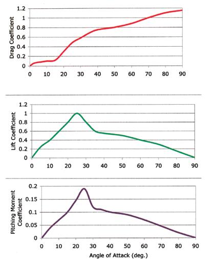
The magnitude of the lift, drag and pitching forces will strongly depend on the attack angle (figure 2). According to Seo (2013), Seo et al. (2012) and Ganslen (1964), lift increases linearly with the angle of attack up to the stalling angle which is at 30°. At that point the discus experiences a sudden decrease in lift and at 90° the lift force is zero. The drag force also increases with increasing attack angle from 0° to 90°. Ganslen (1964) showed that the sudden decrease in lift at 30° also coincides with the formation of a “turbulent wake” behind the discus. Discus performance will be improved if the discus has a relatively flat angle of attack. Once the discus develops an angle of attack to the relative wind, it will continue to exaggerate the “nose up” tendency, which is termed as a positive pitching moment. This implies that a flight path initiated near the point of the stall angle for the discus will necessarily result in a stalled discus with high drag and low lift. Therefore, an optimum attack angle will allow the discus to complete its flight without stalling.
A term that has been used in reference to the attack angle is the maximum lift/ drag ratio and, more specifically, the attack angle at which that maximum ratio occurs. Taylor (1932) and Ganslen (1964) found that the maximum value of the ratio occurred at an attack angle of 9°. This value seems to be in conflict with a generally accepted negative optimal angle of attack. Hay (1985) attributed this discrepancy to the ever changing angle of attack during the discus’s flight speculating that the optimum angle obtained at release will be the one that would yield the best results overall and not at a particular instant in flight. On the other hand, Hubbard (1989) mentioned that the lift/drag ratio is a concept used in aircraft design to resolve issues related to the maximization of the steady cruising range of an aircraft. He stated that this ratio is irrelevant in a discussion of the transient behavior of a discus and that, as an aerodynamic term, it should disappear from the discus literature.
RELEASE ANGLE, ANGLE OF TILT, INCLINATION ANGLE
Terauds (1978) reported that the angle of tilt at release should be at 15°, which he probably estimated from field or film observations. Soong (1976), found that with reasonable initial discus rotation, the release angle and the angle of inclination have a large effect on the range. At zero wind, the optimum combination of release angle and inclination angle is 35°/26° respectively if they vary independently. If they vary together, that

FIGURE 1. AERODYNAMIC FORCES AND ANGLES DURING THE DISCUS FLIGHT. TOP: VIEW FROM THE SIDE, BOTTOM: VIEW FROM THE BACK. RED ARROW DEPICTS THE PITCHING MOMENT. CG=CENTER OF GRAVITY, CP=CENTER OF PRESSURE.
FIGURE 2. DEPENDENCE OF AERODYNAMIC COEFFICIENTS ON THE ANGLE OF ATTACK (ADAPTED FROM HUBBARD & CHENG, 2007).
optimum is at 33°. However, the former ratio will result in a 1.55 meters gain in range. Frohlich (1981) agreed that the optimum strategy in still air is to release the discus so that the inclination angle is about 5 to 10° less than the release angle. Although this results in negative lift during the early stages of the flight, it allows for a minimum of drag and optimum average lift throughout the upward part of the discus flight. Results from optimization studies that assumed a 0° angle of tilt indicate that for elite throwers, the discus should be thrown at release angles between 35-37°, inclination angles of 26-27°, and attack angles between -9 and -10°. Slightly higher release angles and more negative angles may be more suitable for throwers capable of lesser release speeds. Voigt (1972) claimed that by modifying his data to account for a -17° tilt angle at release, the range will improve by 2.7 meters. Hubbard & Cheng (2007) reported a maximum range of 69.39 meters with a men’s discus released at windless conditions with a release speed of 25 m/sec. and a rotation of 6.6 rev/sec. with an angle of release at 38.4°, inclination angle at 30.7°, and a tilt angle of 54.4° and attack angle at -4°. Deviations of several degrees of any of the first three values while holding the other two constant will result in a minimum decrease of the range achieved, i.e., less than 39 cm. Larger departures, in the order of tens of degrees, will result in a range decrease of approximately 5 meters. Generally, range is most sensitive to the release angle and least sensitive to the tilt angle at release. For both men’s and women’s discuses, the optimal initial conditions of the angles of release, inclination and tilt, will vary significantly with wind speed. There has been a considerable discussion regarding the need for the presence or not of a tilt angle at release. According to Hubbard & Cheng (2007), it is optimal to release the discus tilted significantly so that the lift vector can remain vertical throughout much of the flight, especially near the end of it. The angle suggested was at 54.4°. That angle will gradually decrease (see explanation of this effect under the discus rotation section below), from 54° and will remain at 15° before landing for a nearly flat impact. Although there may be an initial loss of early vertical lift from that initial tilt, the eventual plane reorientation to nearly horizontal overcomes that disadvantage because the tilt results in larger average aerodynamic forces. Regarding the optimum tilt angle, casual observations of throwers may show that they release the discus with a tilt angle quite smaller than 54°. It may be that the application of a theoretical optimum angle may in the end detract from the throwers’ ability to maximize release velocity or other release parameters.
WIND VELOCITY
It is a well established fact that for both men’s and women’s discuses, longer throws can be achieved throwing the discus against fairly strong winds than with the wind or no wind (figure 3). The increases in range due to lift are larger than the decreases due to drag and the discus can always fly further in air than in vacuum (Hubbard & Cheng, 2007). In an early investigation, Taylor (1932), found that head winds between 7 and 8 mph were advantageous, that this advantage decreased progressively and at 14.5 mph became a disadvantage. He also found that tail winds of up to 14 mph were also detrimental to the range achieved. However, Frohlich (1981) using mathematical modeling, found that a discus will travel about 6 meters further if thrown in a 7.5 m/sec (16.8 mph) head wind than if thrown with the wind, and 8.2 meters further if thrown in a 20 m/sec (22.5 mph) headwind than with such wind. A properly thrown discus will always fly further if thrown against winds up to 20 m/sec (45 mph), than with it. This implies that long throws cannot be achieved against extremely strong winds. Theoretically, if the wind velocity is high enough, the discus will stop flying forward and it will actually travel backwards at some point during its flight.
Hubbard & Cheng (2007), employing a 3D dynamic model, reported a 10 and 14 meters advantage for men and women when throwing into a 5 m/sec (11 mph) headwind compared to a 10 m/sec. (22 mph) tailwind. Tutjowitsch (1976) found that if thrown at an negative angle of attack and at a release speed of 23 m/sec, the discus will fly 5.4 meters further if thrown into a head wind of 5 m/sec (11 mph). This value is close to Taylor’s (1932) but quite less that that of Frohlich (1981). Unger (1977) claimed a linear increase in distance for head winds of up to 5 m/ sec (11 mph) with a greater than linear relationship for higher wind speeds, although he provided no support for those claims.
Chiu (2008), employing mathematical modeling, estimated optimal performances when the wind speed fluctuated from -21 m/sec (-47 mph) to 12 m/sec (27 mph). He found that when the head wind was at 17 m/sec (38 mph) the male “virtual” record holder could throw up to 84.27 meters, approximately 10 meters further than the current world record. When the head wind was over 17 m/sec., the range would decrease gradually. Similarly, for the female “virtual” record holder the distance would decrease at head wind speeds of over 13 m/sec (29 mph). Chiu (2008) also found that generally with increased tail wind, thrown distances for both males and females would decrease. However, he also reported a little known observation that, with tail winds of over 7 m/sec (15.7 mph), the ranges thrown for both males and females would begin to increase. Chiu (2008) also reported that when the head wind was approximately 8 m/sec. (18 mph), both male and female “virtual” record holders would obtain their optimal throwing distance provided that the angle of release and the inclination angle were the same. On the other hand, with increased tail wind, the optimal distance could be obtained only when the inclination angle was larger than the release angle.
Regarding the drag and lift coefficients, Frohlich (1981) stated that the measurement of those is probably not accurate for relative wind speeds of over 40 m/sec (90 mph)
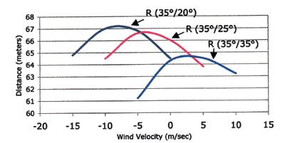
FIGURE 3. EFFECT OF WIND VELOCITY (NEGATIVE SIGN FOR HEADWIND) ON RANGE (R) GIVEN ANGLE OF RELEASE/ANGLE OF INCLINATION. INITIAL SPIN 36.9 REV/SEC, RELEASE VELOCITY 25.5 M/SEC. (ADAPTED FROM FROHLICH, 1981).
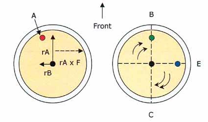
FIGURE 4. VIEW FROM TOP. EFFECT OF AIR ON THE CLOCKWISE ROTATING DISCUS CAUSING GYROSCOPIC PRECESSION (RAXF), AND LATERAL DISPLACEMENT OF THE CENTER OF PRESSURE (A). IN THE RIGHT, A TORQUE ACTING ON POINT B (GREEN DOT), WILL CAUSE A PRECESSION OF THAT TORQUE 90° TOWARDS THE DIRECTION OF ROTATION CREATING A TORQUE VECTOR APPLYING A FORCE UPWARDS ON POINT E (BLUE DOT), CAUSING THE DISCUS TO ROTATE AROUND THE BC AXIS. (ADAPTED FROM BARTLETT, 1992).
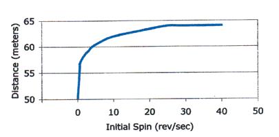
FIGURE 5. EFFECT OF THE INITIAL ROTATION ON THE RANGE. ANGLE OF RELEASE=ANGLE OF INCLINATION=35°, RELEASE VELOCITY = 25.5 M/SEC. (ADAPTED FROM SOONG, 1976).
and that it would not be meaningful to perform any range calculations with wind speeds above 20 m/sec (45 mph).
THROWING IN THE WIND
For moderate winds, i.e., less than 20 m/ sec (45 mph), a discus thrown with a tail wind must be thrown with a different strategy than a discus thrown in a head wind. Frohlich (1981) stated that with a head wind, the discus inclination angle, at release, should be about 10° to 15° less than the release angle so that during the majority of the flight the drag will be kept at minimum and lift at maximum. As the velocity of the wind increases, the release angle decreases making the discus trajectory flatter. This way the discus will not hover for too long and stall towards the end of its flight. On the other hand, for a discus thrown into a tail wind, the release angle should increase, the discus is thrown higher in the air. With tail wind velocities over 20 m/sec (45 mph), longer throws will be obtained if the discus is turned over so the discus catches the wind like a sail would. The worst possible conditions to obtain long throws is to throw in a tail wind of 7.5 m/sec. (17 mph). If the wind velocity is less than about 20 m/sec. (45 mph), longer throws can always be achieved by throwing against the wind (Frohlich, 1981).
Frohlich (1981) also observed that although the longest throws take place against strong winds, it is easier to obtain optimum performances when throwing in a tail wind, in the sense that it is easier or, less technique demanding, for a thrower to produce the optimum release parameters than if throwing in a head wind. For example, to obtain a throw within one meter of the optimum when throwing in a 10 m/sec (22 mph) head wind, the thrower should release the discus at an angle within ±5° of the optimum and at a discus inclination angle within ±3° of the optimum. When throwing in a 10 m/sec (22 mph) tail wind, the thrower could release the discus within ±6°, and ±15° of those angles respectively, to come within the same one meter of the optimum throw. This may imply that throwing in head winds may favor the experienced thrower due to the larger control required to achieve optimum performances. In addition, the effect of a head wind is enhanced as the discus spin increases with the higher the spin, the better the effect of a headwind (Hildebrand et al., 2009).
Hubbard & Cheng (2007) described what they termed a “slicing” strategy
when throwing against strong headwinds of between 6 and 20 m/sec. (13-45 mph). In those conditions it is optimal to initially have the discus symmetry plane (an imaginary plane that equally divides the discus front and back) nearly vertical by decreasing initial inclination and increasing initial tilt substantially (>70°), although the release angle remains relatively constant near 35°. With strong tailwinds very high release angles are optimal. For example, with tail winds at 10.8 m/sec (24 mph), a strategy of 44.3°, 36.7° and 58.6° (release angle, inclination angle, tilt angle) will produce the same result as a 46°, 46.3° and 19.1° strategy, other factors being equal. For large tailwinds, a “kiting” strategy was proposed taking advantage of the fact that in extreme conditions the wind speed may be greater that the discus horizontal velocity. In this case an initially positive angle of attack is chosen which makes both the angle of release and the inclination angle to increase. For a tailwind of 20 m/sec (45 mph), an angle of release at 62° with an inclination angle at 90° is proposed, with the entire flight essentially occurring at that extreme inclination angle, and the discus acting like a sail. Obviously, those optimal theoretical angles for high winds are extremely difficult or impossible to obtain by throwers.
Ganslen (1958) mentioned that a less able thrower will benefit more from a head wind of a given speed than a good thrower, because the percentage increase in the relative wind will be greater for the less able thrower than a thrower who can throw the discus at high velocities. Soong (1976), found that the head wind advantage is lost when the discus inclination angle is too high as it happens when both the angles of release and the inclination angle are 35°.
RELEASE VELOCITY
The paramount factor for optimum performance is the release velocity and all the efforts of the thrower should be geared towards enhancing that value. Aerodynamic forces become more important with increasing release velocity. Up to about 25 m/sec (56 mph), with no wind, the range achieved is more or less the same whether the discus is thrown in a vacuum or in air, although a quite different angle of release should be used to obtain the optimal range for the throw. A discus will go further in air as compared to a vacuum assuming that the release velocity is better than 25 m/sec., or if
DISCUS ROTATION
The most salient effect of the discus rotation around its short axis, is to stabilize its orientation during its flight. Frohlich (1981) reported that at the moment of release, the discus rotates at ~7 rev/sec. However, the effect of the discus rotation had not been studied in all past investigations, many of them assuming that both the pitching and the rolling rates the of the discus are invariable due to the stabilization gyroscopic effect of the discus spin. Soodak (2004) and Hubbard and Cheng (2007) recognized the apparent characteristic of the discus flight to exhibit a slow but uneven rolling of the discus with several degrees of roll occurring in typical flights. The women’s discus exhibits a higher rolling rate than the men’s. This rolling motion alters the direction of the lift vector and prevents the trajectory from occurring in a purely vertical plane. More recently, Rouboa et al. (2013) studied the aerodynamics of the discus with and without rotation. They stated that the rotation motion essentially influences the air resistance as it minimizes the influence of the drag forces and, thus allowing the discus to fly further. If there are no torques acting on it, the initial plane of motion of the discus is maintained throughout its flight. However, in reality, the rotation of the discus generates aerodynamic forces that apply torques which are small but not negligible. A careful observation of the discus during its flight shows that for a right hand thrower, the left side of the discus tilts or rolls progressively downwards at an angle that reaches approximately 10° shortly before the discus lands. This behavior of the discus occurs because the aerodynamic lift forces are larger on the forward half of the discus and tend to make the front edge move upwards. Because of the discus rotation, this upward torque creates a gyroscopic precession, a phenomenon occurring in rotating bodies in which an applied force is manifested 90 degrees later in the direction of rotation from where the force was applied. Therefore, the end result is the creation of a torque vector pointing to the right and causes the right side of the discus to go up (figure 4). Secondly, since the discus rotation causes the relative air velocity to be slightly higher on the left side of the discus (Magnus effect), the aerodynamic forces cause a lateral displacement of the center of pressure to the left. These forces create a torque vector pointing forward causing the front edge of the discus to pitch upward at about 1.5°/sec during its flight which results in a change in the angle of attack which in turn affects the magnitude of the lift later in flight. Those three moment components (i.e., higher forces on the front half, lateral displacement of the center of pressure and, change in the attack angle) will rotate the discus counterclockwise around its long axis, with the left edge moving downwards and the front edge pitching up (Bartlett, 1992). It will also slow the rate of rotation of the discus around its own axis, although that effect is negligible (Hubbard & Cheng, 2007). The latter authors also reported that optimal strategies and ranges for both men’s and women’s discuses depend on initial spin assuming a constant velocity and on release velocity assuming a constant spin. Frohlich (1981) mentioned that because of the symmetrical shape of the discus, a non rotating one would experience smaller aerodynamic torques than a rotating one and that this had caused an expert to suggest that a discus be constructed with a hollow rim filled with mercury in order to reduce that rotation after the release. However, a non-rotating discus lacks stability and will most likely wobble. Such a discus may experience less torque but it will also become less aerodynamic, and eventually the negative effects will outweigh the positive.
Rouboa et al., (2013) using computational fluid dynamics, studied the aerodynamic effects on the discus both with and without rotation. They found that the range of the discus was strongly affected by the drag coefficient, the initial velocity of release, the release angle and the direction of wind velocity. In turn, those variables change as a function of discus rotation. For a variety of angles of release and velocities of release they tested, the rotating discus had an advantage over the non rotating one. For example for release speeds of 25 m/sec (56 mph) and 27 m/sec (60 mph), a rate of rotation at 4 rev/sec, an angle of release at 34°, angles of attack varying between 0° and 90° and, a head wind of 10 m/sec (22 mph), there was a gain of the rotating discus of 2 meters and 5 meters respectively for those two release speeds. They also calculated that the rotation of the discus does not alter the vertical distance of the throw. However, those authors did not specifically mention whether the rota-
0°
FIGURE 6. EFFECT ON DISCUS ROTATION OF A SIDE WIND FROM THE RIGHT (B) OR LEFT (A), FOR A RIGHT HAND THROWER.
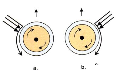
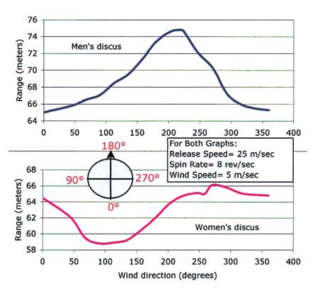
FIGURE 7. EFFECT OF DIRECTION OF WIND ON THE RANGE OF THE DISCUS. 180°= STRAIGHT HEAD WIND, 0°= STRAIGHT TAIL WIND. LEFT HAND THROWERS SUBTRACT FROM 360°. (ADAPTED FROM HILDEBRAND ET AL., 2009).
tion of the discus affects drag, lift and pitch. Regarding that issue, Seo et al. (2012), found little difference between the aerodynamic coefficients of drag, lift and pitching moment whether the discus was spinning or not. Voigt (1972) reported a 3.75 meters increase in range if the spin was increased from 5 to 16 rev/sec. with a release speed of 20 m/sec.
Soong (1976) also tested the effect of the speed of rotation of the discus. He found that with a 25.5 m/sec. speed of release and a discus rotation speed from 0 rev/sec to 37 rev/sec, there was an increase of 13.76 meters attributed to the discus rotation (figure 5). Although he tested higher rotation speeds, he found out that values beyond the speed of ~37 rev/sec., will not change the range achieved, but that the pitching and rolling motions could be reduced. Hubbard & Cheng, 2007, argued that the optimal initial spin rates they calculated, using 3D models, of 4 rev/sec. and 7 rev/sec. for men’s and women’s discuses respectively, indeed allow for an advantageous orientation of lift later in flight something that much higher spin rates would probably not allow. Hildebrand et al. (2009) similarly found that the best throw is obtained at the highest spin rate. Their numerical results were very close to those of Soong (1976) although the former authors studied rotation speeds between 6.3 and 14 rev/sec. By the same token, for a men’s discus spinning at 14 rev/sec., the optimal wind is a straight head wind (in line with the direction of the throw). At the same spin rate, a head wind at 50° from the right is optimal for the women’s discus. As the spin rate decreases, the optimum wind direction generally shifts from a head straight wind (0°), to the right (90°) and the throwing range also decreases.
MOMENT OF INERTIA
The dimensions and the mass of the discus are specifically determined by the rules of the sport, but there are no specifics regarding the moments of inertia of the discus, which essentially means that there are no restrictions as to the distribution of the mass around the center of the implement. The force required to stop a rotating object depends on the product of the mass of the object and the square of the distance from the axis of rotation
to the particles that make up the body (I= m r²). The further the distribution of the mass from the center, the greater the moment of inertia of the rotating object. Inertia simply expresses the degree of resistance in altering the given state of an object. Discuses with large moment of inertia have most of their weight towards the edge of the discus. Assuming that adequate rotation is imparted on such a discus, it will be increasingly difficult to alter its state of rotation, i.e., to slow it down. Indeed, most discus throwers have a tendency to prefer throwing discuses in which most of the mass is concentrated toward the rim. The large moment of inertia of those discuses, that resists changes, make them less prone to adverse aerodynamic torques. Since a discus with large moments of inertia is less likely to spin out of its previous rotational plane, the highest density of the discus should be on its circumference (Hildebrand, 2001).
These days companies offer a plethora of discuses with a variety of weight distribution. The wise thrower will choose the discus that will suit her capabilities. More may not always be better when it comes to the moment of inertia of the discus. Soong (1976) studied the effect of the discus moment of inertia, as a function of the rate of discus spin, comparing two men’s discuses, one with a 22.4 mm., rim thickness (most commonly used discuses) and another with 28.2 mm. The former presented inertia of 157.61 gm/cm/sec², while the latter, 182.5 gm/cm/sec². He found that the ratio of the moment of inertia to the weight of the commonly used discus, is already sufficiently high. Further effort in redistributing the mass will not produce significant improvement in the throw. The maximum distance advantage of the thicker rim discus was at the spin rate of 8 rev/sec., and it was about 44 cm, while at the speed of 4 rev/ sec., the gain was 1 cm.
OTHER EFFECTS
Side Winds. Simulation research has not extensively studied the effect of side winds. Experience with throwing against head side winds strongly supports the advantage of those winds. In an observation of a number of practice throws, Pharoah (1957) speculated that the optimum wind direction is from 20° to the right of the throwing direction. Frohlich (1981) also mentioned that head winds blowing from the right side (right hand throwers) would allow for even longer throws than those obtained with direct headwinds. He suggested that in those conditions the thrower would want to release the discus with the highest point of its rim towards the direction of the wind. He further explained that with the wind being from the right, it will reach the discus at oblique angles, and that the relative wind velocity will be smaller compared to a direct headwind. This will cause both the drag and the lift to be reduced. However, longer distances may be obtained since some of the drag forces would act perpendicular to the direction of flight thus reducing their negative effect on the discus. In addition, Terauds has addressed that for a right hand thrower, the side wind from the right, would also serve to maintain the gyroscopic stability of the discus by enhancing the rotation of the discus since its right side moves with the wind (figure 6 b) rather than in opposition (figure 6 a). For left hand throwers, the same phenomenon is true for a wind from the left and a counterclockwise rotation of the discus. Hildebrand (2001) further mentioned that with headwinds, the discus rolls from a generally horizontal position to a nearly vertical one which tends to make it lose lift. His computer simulation showed that the head wind from the right is more beneficial because it hinders the rotation of the discus around its long axis (axis BC in figure 4), and preventing, or better delaying, the discus from assuming a vertical position.
Hildebrand et al. (2009) applied 3D simulation to study the optimal release conditions given a constant wind of 5 m/ sec. (11.2 mph) blowing from a variety and all directions, for both the men’s and the women’s discus. Figure 7 shows the effect of the wind on the range. For the men’s discus, a wind from the right at 40° in relation to the direction of the throw (220° in figure 7), was the optimal, given a release velocity at 25 m/sec., an angle of release at 33 degrees and an initial spin at 8 rev/sec. For the women’s discus, a wind exactly from the right, 90° in relation to the direction of the throw, (270° in figure 7), was optimal, given 24 m/sec. release velocity, 41° angle of release and 8 rev/ sec initial spin rate. According to those authors, for the men’s discus, the result is a straightforward one in that a direct tail wind is the worst and a head wind from the right is the optimal. However, for the women’s discus, the optimal wind comes from the right at a right angle to the direction of the throw (90°), with winds from the left being the worst. It is interesting to note that the results of Hildebrand et al. (2009) show that a women’s discus will travel about the same with a direct tail wind or a wind from the right at approximately 30° in relation to the throw (210° in figure 7), assuming all other variables are constant. Also, based on the same results, for the men’s discus, a thrower who is throwing the discus in a wind exactly from the right (90°), would gain about 1.2 meters if he adjusted his technique so that the direction of the discus flight shifts about 15° to the right (195° in figure 7).
Effects of Discus Area (A), Mass (M), Air Density (ρ). The effect of the aerodynamic forces is proportional to the quantity ρA/M. In those quantities, the mass and area of the discus are fixed values, whereas the air density can fluctuate among places depending on temperature and altitude. Frohlich (1981) reported that, assuming same release velocity, lower effective mass discuses fly further, particularly in a head wind. In still air, for every kilo in mass reduction there are 47 cm. gain in distance, whereas in a headwind of 10 m/sec., (22 mph) the gain in distance is approximately 3 meters for every kilo in mass reduction. This implies that, if released at the same velocity, a women’s discus will travel 47 cm. further than the men’s in still air and 3 meters further in a headwind of 10 m/sec., due to the better overall aerodynamics of the reduced surface women’s discus. When the effective mass is reduced, the thrower will need to reduce the release angle to obtain the optimum distance. Therefore, women discus throwers should release their discus several degrees smaller than the suggested optimum for the men’s discus. Men discus throwers throwing at high temperatures and high altitudes should release at angles several degrees beyond suggested optimal. Hildebrand et al. (2009) also attributed differences between the men’s and women’s discuses, as to the optimal direction of the wind, to differences in the discus effective mass.
Better performances, although not significantly better, can be achieved at low temperatures (cold air is denser than warm air) due to the effect of air density on the aerodynamics. A discus will fly 13 cm. further at 0° C (32° F) than at 40° C. (104° F). Under the same conditions it will fly 90 cm. further with a 10 m/sec. (22 mph) headwind. For every 10 mm Hg increase in the atmospheric pressure there is an increase of 1.2 cm in distance if thrown in still air, and 8.1 cm. in 10 m/
sec headwind.
Effects of Gravity, Orientation and Release Height. Because the gravitational acceleration varies less than 0.5% among places on Earth, changes in that acceleration have little effect on discus range. A discus will fly 19 cm. further in still air at the elevation in Athens, Greece rather than at the elevation of Mexico City; the same discus will fly 34 cm further at the equator than in the poles. Moreover, because of the earth’s rotation, any projectile will travel longer if released eastward than westward, assuming no differences in any of the other factors affecting the distance thrown. The distances gained will be minimal though.
Regarding the release height, Frohlich (1981) reported that it appears that releasing the discus 1 meter higher will result in a 2 meter longer range. Since such increases in release height are impractical, those gains can be generalized and assumed to be approximately 10 cm for every 5 cm increase in release height.
REFERENCES
Bartlett, R.M. (1992). The biomechanics of the discus throw: a review. Journal of Sports Sciences, 10: 467–510.
Chiu, C. (2008). Estimating the Optimal Release Conditions for World Record Holders in Discus International Journal of Sport and Exercise Science, 1(1): 9-14
Frohlich, C. (1981). Aerodynamic effects on discus flight. American Journal of Physics, 49:1125–1132.
Ganslen, R.V. (1964). Aerodynamic and mechanical forces in discus flight. The Athletic Journal, 44:50, 52, 68,88-89.
Ganslen, R. (1958). Aerodynamic forces in discus flight. Scolastic Coach, 28, 46, 77.
Hay, J. (1985). The Biomechanics of Sports Techniques (3rd Edition). Prentice Hall, Englewood Cliffs, NJ.
Hildebrand, F., Schuler, A., & Waldmann, J. (2009). Optimization of discus flight. 27th International conference on Biomechanics in sports, A. Harrison, R. Anderson, & Kenny, I (editors).
Hildebrand, F. (2001). Modeling of discus flight. Biomechanics Symposia, University of San Fransisco., pp. 371-374.
Hubbard, M. (1989) The throwing events in track and field. in: C.L. Vaughn (Ed.) Biomechanics of Sport, CRC Press, Boca Raton, FL;213–238.
Hubbard, M. (2000). The Flight of Sports Projectiles, in Biomechanics in Sport: Performance Enhancement and Injury Prevention (ed V. M. Zatsiorsky), Blackwell Science Ltd, Oxford, UK.
Hubbard, M., & Cheng K. (2007). Optimal discus trajectories. Journal of Biomechanics, 40, 3650-3659.
Johnson, C., & Jansson, J. (2015) The secret of flight. Public Domain, https://secretofflight. wordpress.com/
Kazuya, S., Shimoyama, K., Ohta, K., Ohgi, Y., & Kimura, Y., (2012). Aerodynamic behavior of a discus. 9th Conference of the International Sports Engineering Association, ISEA 2012, 34, 92-97.
NASA. Public Domain, https://www.grc.nasa. gov/www/k-12/airplane/wrong1.html
Pharoah, M. (1957). Observations on discus throwing. AAA Coaching Newletter, 4, 9-10.
Rouboa, A., Reis, V., Vishveshwar, M., Marinho, D., & Silva, A. (2013). Analysis of wind velocity and release angle effects on discus throw using computational fluid dynamics. Computer Methods in Biomechnaics and Biomedical Engineering, 16, 1, 73-80.
Seo, K. (2013). Aerodynamic characteristics around the stalling angle of the discus using a PIV. 10th International Symposium on Particle Image Velocimetry, Delft, The Netherlands, July 1-3 ,2013
Soodak, H. (2004). Geometric top theory of football, discus, javelin. In: Hubbard, M., Mehta, R.D., Pallis, J.M. (Eds.) Engineering of Sport 5: Proceedings of the Fifth International Conference on the Engineering of Sport, Davis, CA, vol. 1. September. ISEA, Sheffield, UK, pp. 365–371.
Soong, T. (1976). The dynamics of discus throw. Journal of Applied Mechanics, 98:531–536.
Taylor, J. (1932). Behavior of the discus in flight. The Athletic Journal, April:9–10.
Tutevich, V. (1976). Theorie der Sportlichen wurfe teil 1. Leistungsport, 7:1–161.
Terauds, J. (1978). Computerised biomechanical cinematography analysis of discus throwing at the 1976 Montreal Olympiad. Track and Field Quarterly Review, 78:25–28.
Unger, J. (1977). Throwing in the wind. Modern Athlete and Coach, 15, 31-32.
Voigt, H. (1972). Wirkungen der luftkrafte auf die flugweite beim diskuswerf. Der Leibeserziehung, 21:319–326.x
DR. ANDREAS MAHERAS IS THE THROWS COACH AT FORT HAYS STATE UNIVERSITY IN KANSAS AND IS A FREQUENT CONTRIBUTOR TO TECHNIQUES.
The Full Names and Complete Mailing Addresses of the Publisher, Editor and Managing Editor are: Sam Seemes, Mike Corn, 1100 Poydras St., Suite 1750 New Orleans, LA 70163.
Techniques is owned by USTFCCCA, 1100 Poydras St., Suite 1750 New Orleans, LA 70163.
The Average Number of Copies of Each Issue During the Preceding 12 Months: (A) Total Number of Copies (Net press run): 7.080 (B3) Paid Distribution Outside the Mails Including Sales Through Dealers and Carriers, Street Vendors, Counter Sales and Other Paid Distribution Outside USPS: 0 (B1) Paid Circulation through Mailed Subscriptions: 7,020 (C) Total Paid Distribution: 7,020 (D4) Free Distribution Outside the Mail: 0 (E) Total Free Distribution: 0 (F) Total Distribution: 7,020 (G) Copies not Distributed: 60 (H) Total: 7,080 (I) Percent Paid: 99%
The Number of Copies of a Single Issue Published Nearest to the Filing Date: (A) Total Number of Copies (Net press run): 6,480 (B3) Paid Distribution Outside the Mails Including Sales Through Dealers and Carriers, Street Vendors, Counter Sales and Other Paid Distribution Outside USPS: 0 (B1) Paid Circulation through Mailed Subscriptions: 6,420 (C) Total Paid Distribution: 6,420 (D4) Free Distribution Outside the Mail: 0 (E) Total Free Distribution: 0 (F) Total Distribution: 6,420 (G) Copies not Distributed: 60 (H) Total: 6,480 (I) Percent Paid: 99% Signed, Sam Seems
STATEMENT REQUIRED BY TITLE 39 U.S.C. 3685 SHOWING OWNERSHIP, MANAGEMENT AND CIRCULATION OF TECHNIQUES, Publication #433, Published Quarterly at 1100 Poydras Street Suite 1750 New Orleans, LA 70163. The business office of the publisher is 1100 Poydras St., Suite 1750 New Orleans, LA 70163.
