Discharge formula for Thin Plated Rectangular Lab Fabricated Sharp Crested Weirs
Shrikant A. Tekade1, Tejas P. Bhatkar2
3
, Yuvraj A. Chavhan1Assistant Professor, Department of Civil Engineering, Government College of Engineering, Nagpur, India
2Geotech Engineer, Anandjiwala Technical Consultancy, Nagpur, India
3Assistant Professor, Department of Civil Engineering, Shri Balaji Institute of Technology & Management, Betul (M.P.), India
Abstract: Sustainable development and efficient management of water is an increasingly complex challenge all over the globe. Sharp crested weir is used as a flow measuring device for open channel flow measurement. In rural India the measurement of flow is major challenge at field level because for flow measurement weir sections are made from standard procedure and also by using standard material prescribed in standard codes. In present experimental study sharp crested weir sections are made by mild steel and galvanized steel having a different crest height and width of weir opening are fabricated and tested in the laboratory. The present paper determines the feasibility of sharp crested weir of different material as a flow measurement device for open channel. Experimental data are generated to develop the relation between discharge vs. head over the weir and concluded that the coefficient of discharge value for each weir is same. Based on the experimental data a generalized weir equation for sharp crested weirs is proposed.
Keywords: Open channel flow, Flow measurement, Coefficient of discharge, Rectangular weir.
I. INTRODUCTION
Open channels are used for transportation of water for irrigation. Various advance techniques are used for open channel discharge measurement, to achieve the quantitative measurement effectively. But the initial as well as the maintenance cost is very high. To solve this problem the simplest and easier way can be the use of weir. A rectangular weir is a section having simple rectangular or other shape made by any material and inserted in the cross section of the channel for measuring the discharge. The form of head generated over the crest of weir is useful for measuring discharge. The weir can be classified into two types as sharp crested weirs and broad crested weirs. The nature of the crest segment for sharp crested weir is thin having thickness up to 2 mm, whereas for broad crested weir it is large.
Francis (1883) carried out experimental work on long weirs having a crest length up to 10 feet. From experimental analysis a discharge equation for fully contracted rectangular weirs was proposed. and it was also mentioned that the values of discharge coefficient are constant for specific long weir section.
Rehbock (1929) carried out experimentation on weir section and based on the experimental results investigator proposed a coefficient of discharge (Cd) empirical equation as,
Also it was documented that the Cd value depends on the ratio of p h where h is head over the weir and p is crest height of weir.The ranges for p was 0.10 m p 1.0 m and for h was 0.025m h 0.60 m respectively.
International Journal of Civil and Structural Engineering Research ISSN 2348-7607 (Online) Vol. 7, Issue 1, pp: (71-82), Month: April 2019 - September 2019, Available at: www.researchpublish.com
Kindsvater and Carter (1959) proposed equation for all types of thin plated rectangular weirs 2 3/ 1e e e h L C Q (2)
Where Q discharge in cubic feet per second, e is a subscript denoting “effective”, Ce is effective coefficient of discharge (ft1/2/s), Le = L+Kb, h1e = h1+Kh
Kb is a correction factor to obtain effective weir length, L is measured length of weir crest in feet, B is the average width of approach channel (ft), h1 is head measured above the weir crest in feet , Kh is a correction factor with a value of 0.003 ft. There is variation in the discharge coefficient due to varying width and head. This equation was used for calibration. Ramamurthy et. al. (1987) carried out experimental work on two dimensional sharp crested weir. The pressure distribution on the face of weir was obtained by relating velocity and pressure distribution in the region of nappe. Investigator generates a relationship between Cd and parameter H/W where H is driving head and W is weir height derived by using the momentum principle. Swamee (1988) proposed expression for coefficient of discharge (Cd) on the basis of Kindsvater and Carter as,
Prabhata k. Swamee (1988) studied various discharge formulae’s made by researchers and developed a generalized weir equation for sharp crested, narrow crested, broad and long crested weir. The generalized weir equation give good results for the variation of head/weir height ratio and head/weir width ratio.
Taking into consideration energy principle, Bos (1989) derived general flow equation for sharp crested weir (SCW) by neglecting viscous effect and streamline curvature due to weir contraction. 2 3/ 2 3 2 gbh C Q d (4)
Where Q is discharge, b is weir width, h is head over the weir, g is acceleration due to gravity and Cd is discharge coefficient.
J. Martinez et. al. (2005) carried out experimental work on compound sharp crested weir having two triangular parts with different notch angles. The investigators concluded that the compound sharp crested weir provides accurate measurement for a wide range of flows and proposed the procedure for estimation of discharge coefficient and its validation. Xin Zhang et. al. (2009) investigated the discharge coefficient equation for clinging flow and from the experimental results they concluded that the transition from clinging to free flow does not occur at the same head. Aydin et. al. (2011) carried out experimental work on rectangular sharp crested weir to develop the relationship between weir height and width with discharge by investigating the hydraulics of flow using a sharp crested weir. Analysis of experimental results showed that, discharge is independent of weir height and width.
Bagheri and Heidarpour (2012) investigate flow characteristics of rectangular sharp crested weir for different heights, width and three dimensional velocity by using an Acoustic Doppler Velocity meter. Further which developed an expression for the angle of spilling jet (Ψ), by analyzing various velocity profiles and considering various hydraulic parameters such as width and crest of the weir.
From the literature survey, it is observed that the discharge and Cd value mainly are governed by weir dimensions. Generally for the calculation of Cd value the weir made by brass material according to ASTM standard was used, but no attempts were made to study the change in material such as Galvanized Iron and Mild steel sheets on hydraulics properties of sharp crested weir. According to Bos (1989) the minimum weir height should be 10 cm but in the present experimental study the weir height was selected more than 10 cm shown in table- 1.In the present paper detailed procedure of ASTM standard was followed for fabrication of rectangular SCW using galvanized steel (G. I.) and mild steel (M. S.). The weirs were made by G.I. and M.S. crest height (P) varied for a different b/B ratio where b- width of weir opening, B- width of channel, P- crest height shown in Table -1.
International Journal of Civil and Structural Engineering Research ISSN 2348-7607 (Online) Vol. 7, Issue 1, pp: (71-82), Month: April 2019 - September 2019, Available at: www.researchpublish.com
Table 1: Dimensions of Fabricated Rectangular weir section.
Material b (m) B (m) P (m) b/B ratio
G. I. & M.S. 0.2 1.2 0.15 0.167
G. I. & M.S. 0.3 1.2 0.20 0.25
G. I. & M.S. 0.4 1.2 0.25 0.33
The main objectives of the present experimental study are as follows
To determine “Cd” value for newly fabricated weir and validate with standard known values.
To study the effect of variation of crest height and width of weir opening on the head generated over the weir section.
Data from previous published studies to be used for validation purpose of present experimental study.
Experimental set up
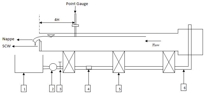
The experiments were conducted in Water Resources Engineering laboratory of the Civil Engineering department at Visvesvaraya National Institute of Technology Nagpur, India. The flume used for experimental work was rectangular and non tilting in nature, having 4.2 m long and 1.20 m in width shown in Fig. 1. For generation of smooth flow in channel, proper stilling and converging vertical plates were used at the inlet section. A 3 HP pump of standard rating curve make drives the circulating mechanism to work efficiently for the flume. A perplex glass sheet was fixed as side walls for visualization. For water surface elevation and bed elevation a vernier type gauge with accuracy 1 mm was used . For discharge measurement electromagnetic flow meter connected to a 0.12 m diameter pipe was used. The rectangular SCW made by G.I and M.S. materials were then fixed at the downstream end of the flume. At the downstream end of flume the water was collected in a volumetric tank with dimension 2×1 m. For preventing the instrumental error, proper calibration procedure were adopted before every run of experiment and Discharge was not varied for individual run.
Fig 1: Side view of experimental set up (1- Sump tank, 2- Pump, 3- Valve, 4- Electromagnetic flow meter, 5- G.I. stand, 6- 0.102 m dia. Pipe.)
2. METHODOLOGY
Rectangular SCW was fabricated using G.I. and M.S. plates. For the calibration purpose end weir made of brass having wetted beveled edges of 600 angle confirming to ASTM was fabricated and used. After performing experiments on the brass weir plate it was found that the coefficient of discharge (Cd) value is nearly same as standard value of 0.67. After calibration of the flume, brass weir was then replaced by M.S. and G.I. weirs which were fabricated with metal cutting
International Journal of Civil and Structural Engineering Research ISSN 2348-7607 (Online) Vol. 7, Issue 1, pp: (71-82), Month: April 2019 - September 2019, Available at: www.researchpublish.com
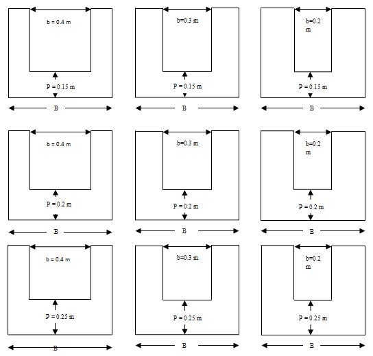
scissors. These weirs were fabricated in the lab itself by procuring the material from local market. Different weir sections were selected having a different b/B ratio as shown in Table 1. To check the variation in b/B ratio the crest height P was varied from 15 to 25 cm by taking 5 cm height as variable. Therefore, 3 sets of the weir were available by varying the width of opening like 20, 30, 40 cm for each crest height shown in Fig. 2. The values of head over weir section and discharge range for different weir or crest height is shown in Appendix- I and II. A point gauge with vernier scale was used to check the accuracy of Cd value which depends on the upstream head over the weir. According to Bos (1989) the point gauge can be fixed at an upstream distance of four times the maximum head. Due to the bottom boundary effect the nature of flow crossing through the weir section should be free flow condition, therefore weir section is used for discharge measurement and discharge can be determined by measuring head over the weir.
Fig 2: Casted weir for different crest height (P) – 03 sets
Dimensional Analysis
A functional relationship between different variables in terms of non dimensional parameters can be obtained by using dimensional analysis. The Buckingham π method was then used to find out the discharge relationship. Under free flow condition the discharge passing through the rectangular weir can be expressed as, Q= f (P,B, b,H, g, ρ) = 0 (5)
Where: Q= Discharge (m3/s), H = Head at specified location (m), B= Width of rectangular channel (m), g= acceleration due to gravity (m2/sec), P = crest height (m), b = opening of weir (m) ρ= Density of water (kg/m3)
International Journal of Civil and Structural Engineering Research ISSN 2348-7607 (Online) Vol. 7, Issue 1, pp: (71-82), Month: April 2019 - September 2019, Available at: www.researchpublish.com
By choosing group of different variables, the dimensionless discharge is
b H K g b Q
Where K is a coefficient and n is exponent.
Experimental Results & Data analysis
1/2 5/2 g b Q =QD and dimensionless head can be represented by b H = HD. Basically dimensionless discharge is an exponential function of dimensionless head and expressed as
(6)
The experimental study aimed at testing the performance characteristics of the weirs fabricated from different materials. The Cd value mainly governs the weir applicability to various hydraulic situations. Hence, the main focus was to find out the Cd value for weir made of G.I. and M.S. material and compare the variation of Q vs. H. Also to find out the head discharge relationship for different b/B ratio by varying width of opening and crest height.
Table 2: Measured head for various discharges
Q (m3/sec) H (m) 0.00196 0.0197 0.00226 0.0214 0.00255 0.0241 0.00293 0.0272 0.00317 0.0295 0.00342 0.0313 0.00374 0.0335 0.00401 0.0345 0.00431 0.0371 0.00462 0.0396 0.00493 0.0413 0.00525 0.0431
Coefficient of discharge (Cd):-
Table 3: Cd values for different location and for different material
Sr. No. Material Cd values at 4h max.
1 Brass 0.661291 2 Mild steel 0.66547 3 Galvanized steel 0.666524
International Journal of Civil and Structural Engineering Research ISSN 2348-7607 (Online) Vol. 7, Issue 1, pp: (71-82), Month: April 2019 - September 2019, Available at: www.researchpublish.com
After experimental runs, it was found that Cd value for each material at 4h upstream is nearly same. Hence it was concluded that hydraulic properties does not change with different material. Therefore, for further experimental study G. I. material is selected for fabricaion of weir. For the G.I weir the parameters such as width of weir (b) and height of crest (P) were varied and different combinations of variations are shown in Fig. 2. Therefore b/B ratio was occurred as 0.167, 0.25 and 0.33 where B is width of channel= 1.2 m. The head discharge relationship for 15, 20 and 25 cm weir heights are shown in Fig. 3.
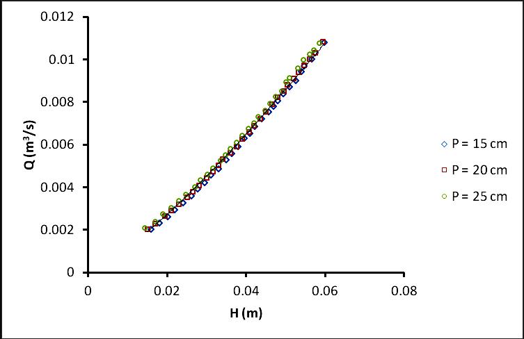
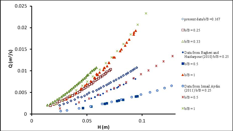
Fig 3: Head- Discharge relationship for various weir heights. The main function of weir plate is to measure discharge, therefore by measuring head over the weir the discharge can be calculated. For precise measurement of head over the weir the maximum velocity in the measuring channel should be limited to 0.55 m/s (Ismail Aydin 2011), which in the present study was strickly followed. After the readings were available for P = 15, 20, 25 cm then the comparison of data with Ismail Aydin (2011) data set having P =2, 4, 6, 8 and 10 cm illustrate in Fig. 4. From the head discharge relationship of Fig. 4 it is concluded that the crest height or weir height of weir has negligible effect on the discharge characteristics of weir hence single head discharge relationship occurred for Ismail Aydin data and for present data set.
Data from Ismail Aydin (2011) from P= 2 cm to 10 cm
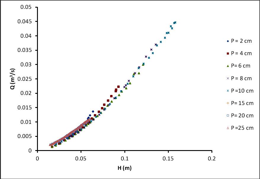
Present data from P = 15 cm to 25 cm
Fig 4: Comparison of present data to data from Ismail Aydin (2011).
International Journal of Civil and Structural Engineering Research ISSN 2348-7607 (Online) Vol. 7, Issue 1, pp: (71-82), Month: April 2019 - September 2019, Available at: www.researchpublish.com
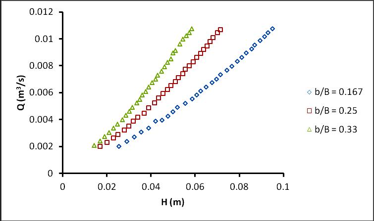
Fig 5: Head- Discharge relationship for Various b/B ratio.
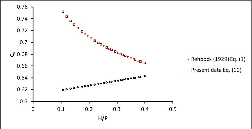
Fig 6: Comparison of present data to data from Ismail Aydin (2011) and Bagheri and Haidapour (2010).
For different b/B ratios the head discharge measurement were performed and shown in Fig. 5. Some data sets of present study having b/B ratios 0.167, 0.25 and 0.33 are compared to data from Bagheri and Heidarpour (2010) and data from Ismail Aydin (2011) for b/B ratios 0.25, 0.5 and 1 shown in Fig. 6. The range of discharge and head is limited by present data sets and range of measurements by Bagheri and Heidarpour (2010).
b/B = 0.33
Fig 7: Comparison of Experimental Cd data to Eq. (1).
International Journal of Civil and Structural Engineering Research ISSN 2348-7607 (Online) Vol. 7, Issue 1, pp: (71-82), Month: April 2019 - September 2019, Available at: www.researchpublish.com
Fig.7 illustrate the comparison of coefficient of discharge (Cd) for b/B = 0.33 obtained from the present data. Eq. (1) as a function of H/p which does not represent, the increase in Cd at low heads. But in field practice the Cd value obtained is large for low heads.
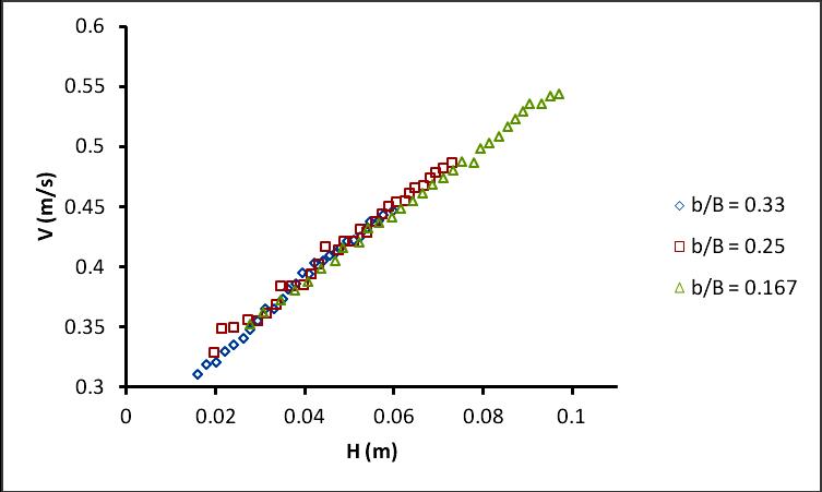
Fig 8: Relationship between velocity vs. head over weir.
Fig.8 shows that plot velocity vs. head over the weir. For zero head the velocity starts from 0.3 m/s. The minimum value of weir velocity is around 0.3-0.35 m/s for all b/B ratios.
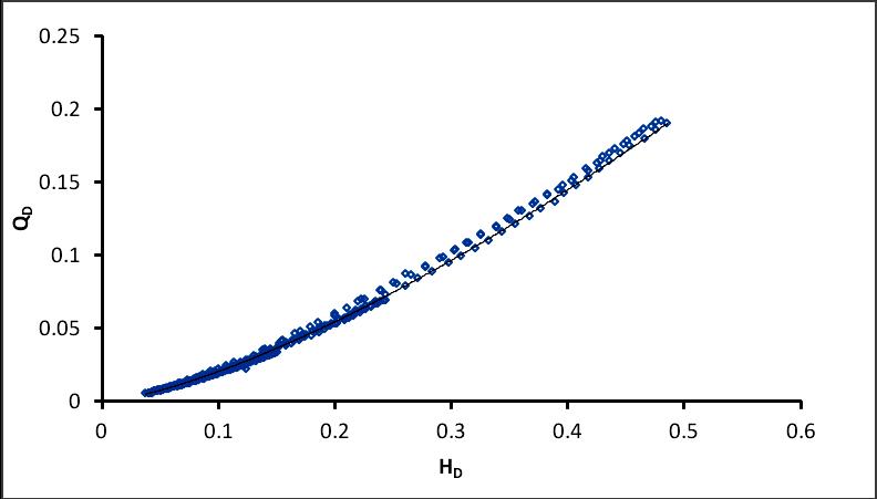
For the total 435 observed value of discharge and head over weir dimensionless discharge (QD) and dimensionless Head (HD) were calculated and regression analysis was carried out between QD and hD which gave the relationship between QD and hD as 4065 1 5258 0 D D H Q (7)
With coefficient of regression (R2) = 0.9963. These observations are shown in Fig. 9
Eq. (7)
Fig 9: Relation between QD vs. HD from experimental data.
International Journal of Civil and Structural Engineering Research ISSN 2348-7607 (Online) Vol. 7, Issue 1, pp: (71-82), Month: April 2019 - September 2019, Available at: www.researchpublish.com
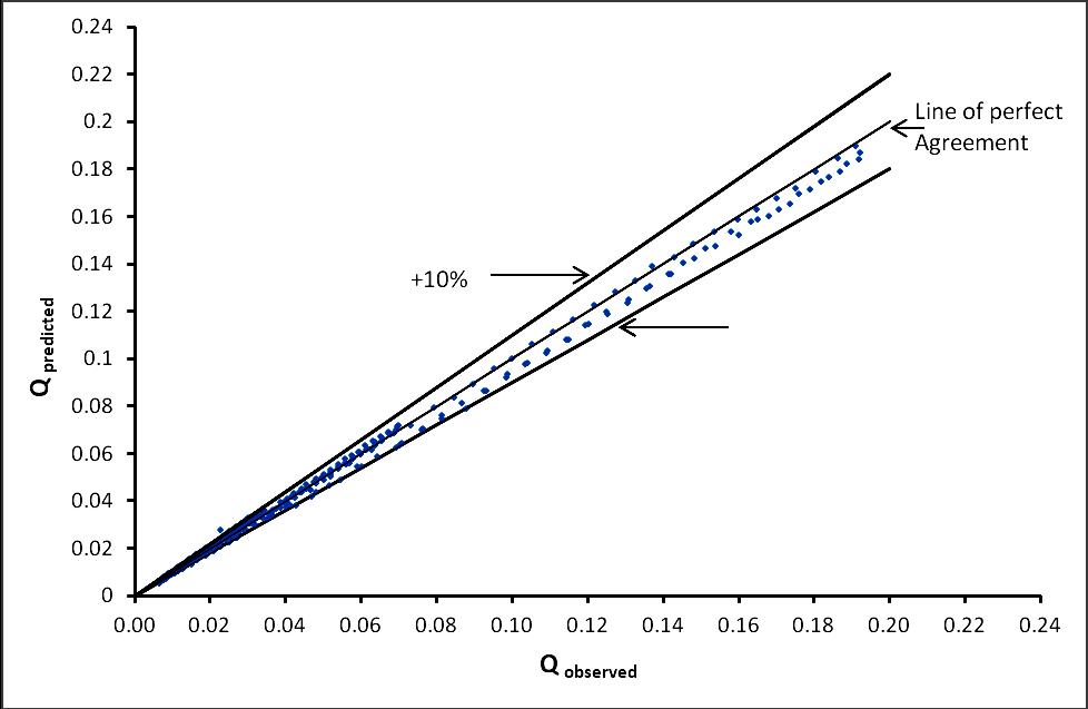
Fig 10: Comparison between obesrved discharge and predicted discharge Fig. 10 illustrate the comparison between observed and predicted discharge. It is observed that an error lies within ±10%. The general flow equation for sharp crested weir is 3/2 2 3 2 H b g C Q d
(8) In more general form the discharge can be expressed in dimensionless form as,
QD and head
2 1/ 2 5/ g b
b H H D
3/2 0.942 b H C Q d D
-10% Eq. (10)
with this variables Eq. (8) can be written as
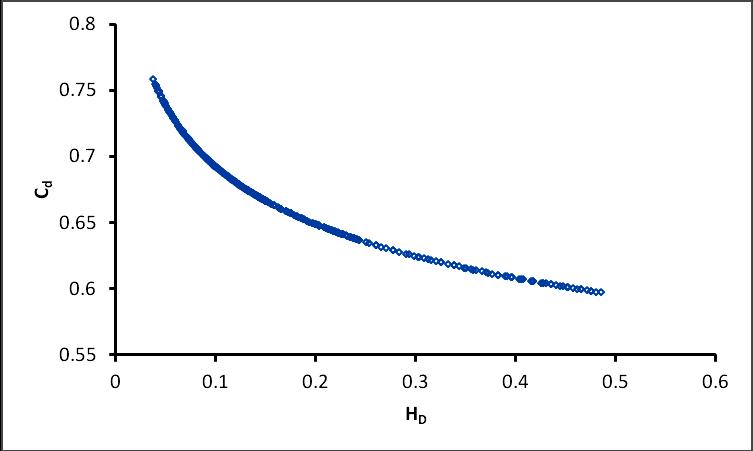
(9) By comparing Eq. (7) and Eq. (9) the value of coefficient of discharge (Cd) is obtained as 0935 0 0.558 D d H C (10) The variation of Cd with respect to HD are shown in Fig. 11
Fig 11: Relation between Cd vs. HD from experimental data.
International Journal of Civil and Structural Engineering Research ISSN 2348-7607 (Online) Vol. 7, Issue 1, pp: (71-82), Month: April 2019 - September 2019, Available at: www.researchpublish.com
It is evident that equation (10) generally agrees with the experimental points and holds good for all value of 0.0375≤H/b≤ 0.485
3. CONCLUSION
Based on the study carried on discharge measurement by rectangular SCW the following conclusions are drawn
Head – Discharge relationship for SCW weir is found to be a exponential series.
The dimensionless discharge for SCW can be expressed as, 4065 1 0.5258 D D H Q
The crest height has a negligible effect on the discharge characteristics of sharp crested weir.
Where, Cd = Coefficient of discharge and its value is given by
0935 0 0.558 D d H C
For precise measurement of head over the weir, the maximum velocity in the measuring channel should be limited to 0.55 m/s. This limitation can be achieved by increasing the weir height and /or decreasing the weir width ratio.
ACKNOWLEDGEMENT
We would like to thanks Bagheri and Heidarpour, Ismail Aydin for providing a part of their experimental data published in “Flow over rectangular sharp – crested weirs” (2010) and “Discharge formula for rectangular sharp crested weirs”. (2011) in digital form.
REFERENCES
[1] American Society for Testing and Materials (ASTM). (1993). “Standard method for open-channel flow measurement of water with thin-plate weirs.” ASTM D5242, West Conshohocken, Pa.
[2] Amruthur S Ramamurthy, Udoyara S Tim, M. V. J. Rao (1987). Flow over sharp crested plate weirs. J Irrig Drainage Eng Vol 113(2), pp 163-172 ,ISSN 0733-9437/87/0002-0163/
[3] Bos MG (1989). Discharge measurement structures. International Institute for Land Reclamation and Improvement, ILRI, Wageningen
[4] Francis, J.B. (1983) Lowell Hydraulics Experiments, D. Van Nostrand, fourth edition, New York.
[5] Ismail Aydin, A. Burcu Altan-Sakarya, Cigdem Sisman (2011). Discharge formula for rectangular sharp-crested weirs. Flow Measurement and Instrumentation, Vol 22(2), pp 144-151 DOI 10.1016/j.flowmeasinst.2011.01.003
[6] J. Martinez, J. Reca, M.T. Morillas and J.G. Lopez (2005) “Design and calibration of a compound sharp crested weir” J. hydraulic Engg. ASCE Vol 131(2) pp 112-116 DOI 10.1061/(ASCE)0733 9429(2005)131:2(112)
[7] Kindsvater, C. E., and Carter, R. W. (1959). “Discharge characteristics of rectangular thin-plate weirs.” Trans. Am. Soc. Civ. Eng.,Vol 124, pp 772– 822.
[8] Rehbock T. (1929) “Discussion of precise weir measurements by EW schoder and KB Turner”. Trans. ASCE, 1929;93;1143-62
International Journal of Civil and Structural Engineering Research ISSN 2348-7607 (Online) Vol. 7, Issue 1, pp: (71-82), Month: April 2019 - September 2019, Available at: www.researchpublish.com
[9] Sara Bagheri, Manouchelr Heidapour (2010) “Flow over rectangular sharp crested weirs”J Irrig. Sci,Vol 28:pp 173179, DOI 10.1007/s00271-009-0172-1
[10] Sara Bagheri, Manouchelr Heidapour (2012) “Characteristics of flow over rectangular sharp crested side weirs”J Irrig.and Drainage Eng, vol 138(6), pp541-547, DOI 10.1061/(ASCE)IR.1943-4774.0000433.
[11] Swamee PK (1988). “Generalized rectangular weir equation”. J. Hydraulic Eng ASCE Vol 114(8) pp 945–949 , ISSN 0733-9420/88/0008-0945
[12] Xin Zhang, Linjuan Yuan, Ruwu Peng, and Zhang Chen.(2009) “Hydraulic Relations for Clinging Flow of SharpCrested Weir”. J. Hydraulic Eng ASCE Vol. 136(6) pp 385-390, DOI 10.1061/_ASCE_HY.1943-7900.0000186
APPENDIX- I
Weir width 0.4 m
P = 0.15 m P = 0.2 m
P = 0.25 m
Q (m3/sec) h (m) Q (m3/sec) h (m) Q (m3/sec) h (m)
0.00201 0.016 0.00201 0.015 0.00208 0.0143 0.00232 0.018 0.0023 0.017 0.0024 0.017 0.0026 0.0201 0.00263 0.0195 0.00273 0.019 0.00293 0.022 0.0029 0.021 0.00304 0.021 0.00325 0.024 0.00321 0.023 0.00336 0.023 0.0036 0.0262 0.00353 0.025 0.00366 0.0248 0.00391 0.0278 0.0038 0.0265 0.004 0.027 0.00422 0.0294 0.00409 0.028 0.00433 0.0285 0.00457 0.031 0.00444 0.03 0.0046 0.0302 0.00487 0.033 0.00474 0.0316 0.00491 0.0316 0.00528 0.035 0.00502 0.033 0.00524 0.0335 0.00559 0.0363 0.00533 0.034 0.00551 0.0348 0.00592 0.038 0.00562 0.036 0.00581 0.036 0.0063 0.0395 0.0059 0.0376 0.0061 0.0375 0.00652 0.041 0.00625 0.039 0.00642 0.039 0.00685 0.0421 0.0066 0.0407 0.00674 0.0405 0.0072 0.044 0.0069 0.042 0.00702 0.042 0.00754 0.0456 0.0072 0.0435 0.00731 0.043 0.00779 0.0469 0.00753 0.045 0.00761 0.0448 0.00806 0.048 0.00788 0.0465 0.00794 0.046 0.0084 0.0494 0.00823 0.048 0.00824 0.0475 0.0087 0.051 0.00851 0.0495 0.00852 0.049 0.00902 0.0525 0.0088 0.0505 0.00894 0.05 0.00942 0.054 0.00909 0.052 0.00915 0.051 0.00968 0.0547 0.00938 0.0532 0.0096 0.053 0.01002 0.0566 0.00971 0.0547 0.00997 0.0544 0.0103 0.0575 0.01001 0.056 0.01023 0.056 0.01079 0.0598 0.0103 0.0574 0.01045 0.0572 0.01083 0.0595 0.01076 0.0585
International Journal of Civil and Structural Engineering Research ISSN 2348-7607 (Online) Vol. 7, Issue 1, pp: (71-82), Month: April 2019 - September 2019, Available at: www.researchpublish.com
APPENDIX – II
Ranges of Experimental data.
P = 0.15 m b (m) B (m) b/B Qmin (m3/s) Q max (m3/s) hmin (m) hmax (m) Vmin (m/s) Vmax (m/s) h/pmin h/pmax
0.4 1.2 0.33 0.00201 0.01079 0.016 0.0598 0.31 0.44 0.106 0.398 0.3 1.2 0.25 0.00196 0.01076 0.0197 0.073 0.32 0.48 0.131 0.486 0.2 1.2 0.167 0.00197 0.01069 0.0276 0.097 0.35 0.54 0.184 0.646 P = 0.2 m
0.4 1.2 0.33 0.00201 0.01083 0.015 0.0595 0.33 0.45 0.075 0.2975 0.3 1.2 0.25 0.00192 0.01071 0.019 0.0724 0.333 0.488 0.095 0.362 0.2 1.2 0.167 0.00204 0.01076 0.028 0.096 0.413 0.55 0.1275 0.48
P = 0.25 m
0.4 1.2 0.33 0.00208 0.01076 0.017 0.0585 0.39 0.47 0.0572 0.234 0.3 1.2 0.25 0.00199 0.01067 0.02 0.0715 0.419 0.51 0.068 0.286 0.2 1.2 0.167 0.00201 0.01074 0.028 0.095 0.41 0.57 0.1016 0.38
Notations:-
Following symbols are used in this paper
Q = Discharge in (m3/s)
Cd = Coefficient of discharge
g = Acceleration due to gravity
b = Weir width (m)
B = Width of channel (m)
H = head over weir (m)
SCW = Sharp crested weir
G.I. = Galvanized iron
M.S. = Mild steel
P = Crest or weir height (m)
K = Coefficient
R2 = Coefficient of Determination
n = Exponent
4H = Upstream distance four times the maximum head over the weir
ASTM = American Standard for Testing Materials
QD = Dimensionless Discharge
HD = Dimensionless head
V = Velocity (m2/s)
