International Journal of Civil and Structural Engineering Research ISSN 2348-7607 (Online) Vol. 6, Issue 2, pp: (207-226), Month: October 2018 - March 2019, Available at: www.researchpublish.com
Dynamic Response of Rectangular Orthotropic Plates Based on Characteristic Orthogonal Polynomials and Rayleigh-Ritz Model
M. E. Ephraim1, T. Ode2, C. A. Ohia31, 2 Lecturer, Civil Engineering Department, Rivers State University, Port Harcourt, Nigeria 3PG Student, Civil Engineering Department, Rivers State University, Port Harcourt, Nigeria
Corresponding author:3chibuike.ohia@ust.edu.ng
Abstract: In this study, the frequencies and mode shapes of thin rectangular plates have been obtained using the Rayleigh Ritz method and characteristic orthogonal polynomials for plates of various boundary conditions. The maximum and minimum frequencies of 23.95 and 9.43 rad/sec were obtained for reinforced concrete plates with all round rigid fixity for aspect ratios of 0.5 and 1.0 respectively. These results clearly demonstrate the crucial role of aspect ratios and boundary restraints. Plates clamped on two adjacent edges and simply supported on the other two (CCSS) and plates clamped on two opposite edges and simply supported on the other two opposite edges (CSCS) yielded intermediate values of fundamental frequencies with the plate with similar restraints on contiguous sides showing the lesser values. It is noteworthy that plate clamped on opposite side and simply supported on the opposite side gave a maximum frequency almost equal to that for all round clamped plate. Rectangular plates with simply supported edges showed the least values of maximum and minimum of 12.08 and 5.17 rad/sec for aspect ratio of 0.5 and 1.0 respectively. The mode shapes followed a sequence of transverse vibrations along the longitudinal, transverse and diagonal axes of the plates. However, there were variations dependent on aspect ratio and boundary conditions. The output of the proposed model is in close agreement with those of other researchers and standard computer software.
Keywords: rayleigh-ritz, characteristic orthogonal polynomials, reinforced concrete, rectangular plates, vibration, ANSYS
1. INTRODUCTION
Plates are extensively used in several engineering fields such as civil, military, marine, and aerospace. In Civil Engineering, they are used in bridge decks, offshore platforms and are predominant in multi-storey buildings. Such wide application of plates across various engineering disciplines makes their vibrational behaviour an important consideration in their structural analysis and design. The transverse vibration of plates has been a subject of many excellent books including Timoshenko and Krieger [1] among others. A lot of research papers have also been published especially on the transverse vibration of rectangular isotropic plates much more than for orthotropic plates. However, the governing equations for a plate, represented by higher order differential equations, are rather difficult to solve analytically except for simple loadings and boundary conditions. This informed the need to evolve approximate methods which are easy to use and can be applied to plates with various configurations.
Approximate general solutions for the natural frequency of orthotropic plates have been achieved with Rayleigh-Ritz method in combination with characteristic beam functions by Hearmon [2], decomposition techniques by Bazely et al. [3] and Marangoni et al.[4] and Gorman superstition by Yu [5]. Further developments include the use of pseudo-Fourier expansion by Rossi et al. [6] and the finite difference method by Chen [7] and Huang et al. [8] The finite element method has also been used to study dynamic response of complicated cases of laminated skewed sandwich plates and tapered beams in the works of Chalak et al. [9] and Bayat et al. [10] respectively.
International Journal of Civil and Structural Engineering Research ISSN 2348-7607 (Online) Vol. 6, Issue 2, pp: (207-226), Month: October 2018 - March 2019, Available at: www.researchpublish.com
Recently, Osadebe et al. [11] investigated the dynamic response of orthotropic plates with the use of characteristic orthogonal polynomials in combination with Galerkin variational principle. However, the models obtained were limited to the determination of the fundamental natural frequencies of vibration only. It is obvious that the study of dynamic response without the analysis of the displacement profile and mode shape is incomplete. In order to address this limitation, the present study adopted the characteristic orthogonal polynomials in combination with Rayleigh-Ritz principle to derive new analytical models for frequency and mode shapes of orthotropic rectangular plates with mixed clamped and simply supported edges.
2. PROBLEM FORMULATION
The problem formulation involved a. derivation of equations for natural frequency of orthotropic rectangular plates based on Rayleigh-Ritz principle. b. development of characteristic orthogonal polynomials for rectangular plates with various combinations of clamped and simply supported boundary conditions.
c. determination of frequencies and mode shapes.
2.1 Formulation of Rayleigh-Ritz Equation for Natural Frequency of Orthotropic Rectangular Plates
The Rayleigh-Ritz principle states that, provided the vibrating system is conservative, the maximum kinetic energy, , must be equal to the maximum potential or strain energy, . For a plate of mass density ρ and constant thickness h, the kinetic energy in two dimensions is represented by the expression ∫ * ( )+ ( ) where - w(x,y) is the transverse displacement of a point located at (x,y) and is usually assumed in the form of a continuous function that approximately represents the shape of the plate’s deflected middle surface. Assuming that the plate is undergoing harmonic vibrations, then the vibrating middle surface of the plate can be approximated by w(x,y,t) ≡ w(x,y) sin t (2) where represents the natural frequency of the plate pertinent to the assumed shape function. Substituting (2) into (1) we have ∫ ( ) ( ) But the kinetic energy is maximum when = 1 Therefore, ∫ ( ) ( ) The maximum potential energy for orthotropic plate is expressed by ⁄ ∫ [ ( ) ( ) ( ) ( ) ] ( ) Equations (4) and (5) can be represented in non-dimensional form using the following coordinate redefinition x= aR and y = bQ where R and Q are coordinates in the X and Y directions respectively
Then, ∫ ∫ ( ) ( ) and
International Journal of Civil and Structural Engineering Research ISSN 2348-7607 (Online) Vol. 6, Issue 2, pp: (207-226), Month: October 2018 - March 2019, Available at: www.researchpublish.com
⁄ ∫ ∫ [ ( ) ( ) ( ) ( ) ] ( )
Equating maximum kinetic energy to maximum total strain energy and introducing the aspect ratio r = b/a, the expression for natural frequency of vibration of orthotropic plate has the form
∫ ∫ [ ( ) ( ) ( ) ( ) ] ∫ ∫ ( ) where ( ) ( ) ( )
In the above equations, A is the area of the plate, , , , and are the flexural and torsional rigidities of the plate, ρ is the mass density of the plate, h is the plate thickness, G, Ex and Ey represent the shear and elastic moduli of elasticity of the plate material respectively.
2.2Development of Characteristic Orthogonal Polynomials (COPs)
Characteristic orthogonal functions were derived for four typical cases of rectangular plates defined by their boundary conditions.
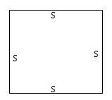
Case 1: Rectangular plate simply supported and clamped on opposite sides (CSCS)
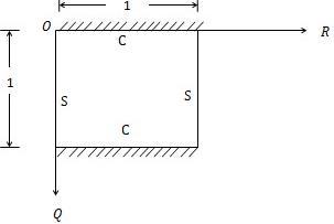
Figure 1 shows a sketch of the plate and its edge restraints, defined in the non dimensional coordinate system R, Q.
Figure 1:Thin Rectangular Plate with CSCS Edge Restraints
The transverse displacement of the plate can be approximated by the product of two orthogonal polynomial functions in R and Q as follows
( ) ( )( ) (9)
The boundary conditions are as follows: deflections at all edges are zero, slope at edge
Q = 0 or 1 is zero, and moment at edge R = 0 or 1 is zero.
Substituting these boundary conditions into (9), the shape function for plate clamped and simply supported on two opposite edges (CSCS) becomes ( ) ( )( ) (10) where K = A4B4
Substituting (10) into (8), the fundamental frequency expression for the plate has the form √ ( ) (11)
International Journal of Civil and Structural Engineering Research ISSN 2348-7607 (Online) Vol. 6, Issue 2, pp: (207-226), Month: October 2018 - March 2019, Available at: www.researchpublish.com
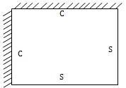
Case 2: Rectangular plate clamped on adjacent edges and simply supported on others (CCSS)
The plate is shown in Figure 2. The following boundary conditions apply
Figure 2: Thin Rectangular Plate with CCSS Edge Restraints
Deflection along all edges are zero, slope at edges R = 0 or Q = 0 is zero, and moment at edges R =1 or Q = 1 is zero. Repeating operations similar to those for case 1, the shape function can be expressed as ( ) ( )( ) (12)
For plate clamped and simply supported on two adjacent edges, the fundamental frequency expression is √ ( ) (13)
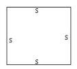
Case 3: Rectangular plate simply supported on all edges (SSSS)
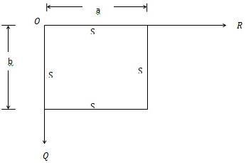
Figure 3 illustrates a sketch of the plate. The following boundary conditions apply: deflections at all edges are zero, moment at all edges is zero.
Figure
3: Thin Rectangular Plate Simply Supported on all edges (SSSS)
Performing similar mathematical substitutions as in previous cases, the shape function becomes ( ) ( )( ) ( )
The fundamental frequency expression of this plate is given as √ ( ) (15)
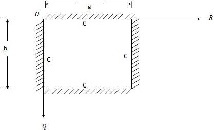
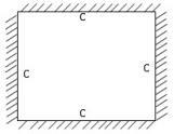
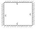
Case 4: Rectangular plate clamped on all four edges (CCCC)
The plate is shown in Figure 4 and has the following boundary conditions: deflections, slopes and moments at = 0, 1; and = 0, 1 are zero.
Figure 4:Thin rectangular plate clamped on all edges (CCCC)
Publish Journals

International Journal of Civil and Structural Engineering Research ISSN 2348-7607 (Online) Vol. 6, Issue 2, pp: (207-226), Month: October 2018 - March 2019, Available at: www.researchpublish.com
Repeating the usual operations as in previous cases, the deflection function is expressed as ( ) ( )( ) ( ) The fundamental frequency expression of this plate is given as √ ( ) (17)
The expressions for the characteristic orthogonal shape functions and fundamental natural frequencies of rectangular orthotropic plates of various boundaries conditions considered are summarized in Table 1.
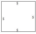
TABLE 1: SHAPE FUNCTION AND FREQUENCY EXPRESSION OF VARIOUS PLATES
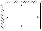
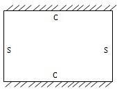
Plate Shape Function and Frequency Expression
CSCS ( ) ( )( ) √ ( ) CCSS ( ) ( )( ) √ ( ) SSSS ( ) ( )( ) √ ( ) CCCC ( ) ( )( ) √ ( )
2.3 Solution Techniques for Frequencies and Mode Shapes for Reinforced Concrete Slab in Rayleigh- Ritz Method
The following procedure was developed for the solution of the equations in Table 1, applicable to reinforced concrete slabs treated in Osadebe et al. [11]
2.3.1Determination of Fundamental Frequencies
1. Calculate moment of inertia, for steel about an axis, in the xx-axis and yy-axis using and respectively.
2. Evaluate area of steel, ,
3. Calculate effective depth, d
4. Evaluate moment of inertia of steel bars about x and y directions and
5. Calculate flexural rigidities about x- and y – axes, Dx and Dy
International Journal of Civil and Structural Engineering Research ISSN 2348-7607 (Online) Vol. 6, Issue 2, pp: (207-226), Month: October 2018 - March 2019, Available at: www.researchpublish.com
6. Evaluate √
7. Calculate from relevant equation in Table 1.
2.3.2
Determination of Other Frequencies and Mode Shapes
Modal analyses of rectangular reinforced concrete slabs of aspect ratios and boundary conditions were performed using ANSYS software. It is known that, there are many types of elements in this software. Some of the elements are suitable for modelling reinforced concrete slabs. SHELL 181 was adopted for this study. The slabs were split into 18 × 9 elements along the length and width with CCSS, CSCS, CCCC and SSSS boundary conditions.
The mode shapes provide useful information that can assist in the design of plates. The understanding and visualization of mode shapes is invaluable in the design process. They help to identify areas of weakness in the design or areas where improvement is needed. The development of a modal model is useful for simulation and design studies
3. RESULTS AND DISCUSSION
The models have been derived on the basis of characteristic orthogonal polynomials (COP) and Rayleigh Ritz method. The validation of the accuracy and reliability of the model was carried out by means of numerical examples and computation with the use of ANSYS computer software. Four cases, involving the combinations of clamped and simply supported edge conditions were considered.
3.1Validation of Proposed Model
For purposes of validation of the proposed model, the problems treated in Osadebe et al. [11] using the Galerkin method were considered. The model parameters are as follows
Modulus of elasticity of steel, Es = 205,000 N/mm2
Concrete characteristics strength, fcu = 35MPa
Possion’s Ratio, μc = 0.20
Thickness of slab, h = 175 mm, Density of reinforced concrete, ρ = 2563 kg/m3 a = 5000mm, for b/a = 0.5, 0.6, 0.7, 0.8, 0.9 and 1.0;
Cover to all reinforcement, c = 25 mm
Diameter of mild reinforcement steel bars = 12 mm
Spacing of steel reinforcement = 150 mm
The computation of frequencies was carried out using the procedure set out in section 2.3.1.The results of the computations using the derived equations are presented in Table 2, from where , it can be seen that the fundamental frequency of vibration of all four types of rectangular plates considered decreased with increase in aspect ratio.
Rectangular plates with simply supported edges showed the least values of maximum and minimum frequencies of 12.08 and 5.17 rad/sec for aspect ratio of 0.5 and 1.0 respectively. The greatest values of maximum and minimum frequencies of 23.95 and 9.43 rad/sec were obtained for plates with all round rigid fixity and aspect ratios of 0.5 and 1.0 respectively. These results clearly demonstrate the crucial role of aspect ratios and boundary restraints on vibration of plates. Plates with CCSS and CSCS edge restraints yielded intermediate values of fundamental frequencies with the plate with similar restraints on contiguous sides (CCSS) showing the lesser values. It is interesting to note that plate clamped and simply supported on the opposite sides (CSCS) yielded frequency values almost equal to those for all round clamped plate (CCCC).
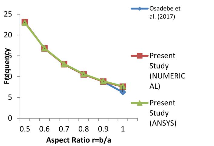
The table further shows that the output from the proposed model are much closer to those obtained from ANSYS computer software, while the model by Osadebe et al. [11], based on Galerkin method, slightly underestimates the fundamental natural frequency of the plates under consideration. On the whole, the proposed model yielded results with about 99 percent accuracy compared to results from ANSYS computer software.
International Journal of Civil and Structural Engineering Research ISSN 2348-7607 (Online) Vol. 6, Issue 2, pp: (207-226), Month: October 2018 - March 2019, Available at: www.researchpublish.com
TABLE 2: VALIDATION OF FUNDAMENTAL NATURAL FREQUENCIES (ω) OF RECTANGULAR ORTHOTROPIC PLATES BASED ON THE PROPOSED MODEL
Fundamental Frequency (ω) radians/sec based on various models
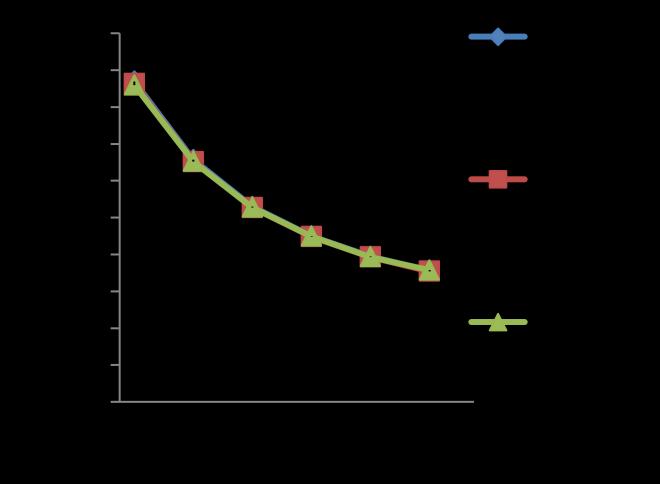
Plate Type Aspect Ratio, r
SSSS
Osadebe et al. (2017) Present Study (NUMERICAL) Present Study (ANSYS)
0.5 12.089119 12.082214 11.922972 0.6 9.299012 9.262356 9.196698 0.7 7.600141 7.596269 7.539822 0.8 6.507281 6.504073 6.471053 0.9 5.732241 5.729466 5.726998 1.0 5.172742 5.170251 5.178978
CCSS 0.5 17.394250 17.276528 17.179485 0.6 13.141580 13.034195 13.036352 0.7 10.596813 10.543409 10.548839 0.8 8.994340 8.956029 8.974901 0.9 7.885202 7.857215 7.859008 1.0 7.105523 7.084651 7.142096
CSCS
0.5 23.088498 23.088122 22.951847 0.6 16.785503 16.763915 16.819458 0.7 12.957086 12.966065 13.051432 0.8 10.525836 10.525628 10.627379 0.9 8.809916 8.809724 8.913954 1.0 6.272057 7.584096 7.684335
CCCC 0.5 23.956242 23.954457 23.749812 0.6 17.854125 17.828493 17.832937 0.7 14.241764 14.240773 14.293618 0.8 12.000379 11.999563 12.078167 0.9 10.477434 10.476731 10.611672 1.0 9.429892 9.429261 9.572433
The closeness of these results is evident from the plots of Figures 5 – 8, showing the variation of the fundamental frequencies of the various plates analysed.
Figure 5: Fundamental natural frequencies, ω of plate simply supported on two opposite edges and clamped on the other two (CSCS)


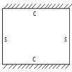


Figure 6: Fundamental natural frequencies, ω of plates clamped on the adjacent edges and simply supported on the two adjacent far edges (CCSS)
International Journal of Civil and Structural Engineering Research ISSN 2348-7607 (Online) Vol. 6, Issue 2, pp: (207-226), Month: October 2018 - March 2019, Available at: www.researchpublish.com
Figure 7: Fundamental natural frequencies, ω of plates simply supported on all edges (SSSS)


3.2Prediction of Higher Frequencies and Mode Shapes
Figure 8: Fundamental natural frequencies, ω of plates clamped on all edges (CCCC)



The computed higher frequencies are shown in Table 3 for the four types of plates considered.
TABLE 3: PREDICTED FIRST FIVE FREQUENCIES IN RAD/SEC
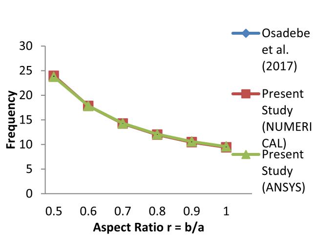
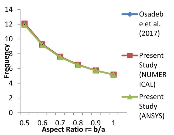
Plate Type
Aspect Ratio 1st Frequency 2nd Frequency 3rd Frequency 4th Frequency 5th Frequency
SSSS 0.5 12.082214 19.347184 32.121528 41.242828 47.991597 0.6 9.262356 16.805007 29.985873 30.126616 37.165669 0.7 7.596269 15.338511 23.264750 29.127590 30.560156 0.8 6.504073 14.324405 18.822538 26.256174 28.177572 0.9 5.729466 13.873273 15.650786 23.386644 29.018891 1.0 5.170251 13.354282 13.354910 21.177476 28.540740 CCSS 0.5 17.276528 24.623803 37.843625 51.513323 56.987234 0.6 13.034195 21.013484 35.046979 36.660784 44.572916 0.7 10.543409 19.026741 29.052192 34.057377 36.431165 0.8 8.956029 17.702874 23.469582 31.168369 32.933315 0.9 7.857215 17.227865 19.482272 27.736493 34.333837 1.0 7.084651 16.567503 16.641016 25.109493 33.785944
CSCS 0.5 23.088122 27.940697 38.307952 54.907499 62.567959 0.6 16.763915 22.293998 33.691696 45.664934 50.878093 0.7 12.966607 19.004122 31.463050 35.024988 40.549164 0.8 10.525628 16.915591 28.056307 29.783554 33.831811 0.9 8.809724 15.711733 23.022219 29.147068 30.091431 1.0 7.584096 14.728414 19.369803 25.710794 29.333050
CCCC 0.5 23.954457 30.991183 44.362429 62.976366 64.075923 0.6 17.828493 25.974688 40.679854 46.177642 52.923269 0.7 14.240773 23.306219 35.648908 39.513695 43.061810 0.8 11.999563 12.078167 21.580856 28.792068 38.169094 0.9 10.476731 21.105847 23.887413 32.665023 40.332394 1.0 9.429261 20.354378 20.355007 29.568041 39.659465
International Journal of Civil and Structural Engineering Research ISSN 2348-7607 (Online) Vol. 6, Issue 2, pp: (207-226), Month: October 2018 - March 2019, Available at: www.researchpublish.com
From Table 3, it can be seen that the frequencies of vibration of all four types of rectangular plates considered decreased with increase in aspect ratio. For plate with CSCS edge restraints, the frequency dropped by about three times from 23.1 rad/sec as aspect ratio increased from 0.5 to 1.0. A similar trend was observed for 2nd – 5th frequency, but with lesser rate of decrease.
The variations of first five frequencies with aspect ratio for plates simply supported on two opposite edges and clamped on the other two (CSCS) and plates clamped on the adjacent edges and simply supported on the two adjacent far edges (CCSS) are shown in Figures 9 and 10.
Frequency
0 10 20 30 40 50 60 70 0 0.5 1 1.5
Aspect Ratio r =b/a
Figure 9: Variation of first five frequencies with aspect ratio for CSCS plate
Frequency
Ratio r=b/a
Figure 10: Variation of first five frequencies with aspect ratio for CCSS plate
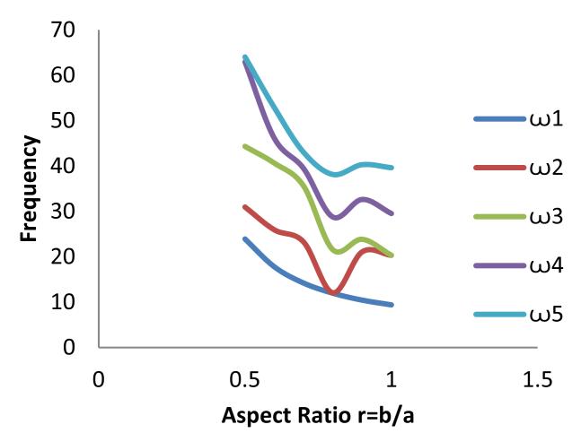
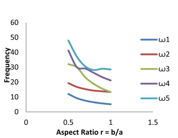
1, ꙍ2, ꙍ3, ꙍ4 and ꙍ5, exhibit a downward trend between aspect ratios of 0.5 and 1. For plates clamped and simply supported on two adjacent edges (CCSS), the first four frequency values decreased gradually with increase in aspect ratio. The fifth frequency value, however, exhibited an upward turning point between aspect ratios 0.8 and 1.
For plate with CSCS edge restraint, all five frequencies
Figures 11 and 12 show the variation of first five frequencies with aspect ratio for plates simply supported on all edges (SSSS) and plates clamped on all four edges (CCCC).


Figure 11: Variation of first five frequencies with aspect ratio for SSSS plate
Figure 12: Variation of first five frequencies with aspect ratio for CCCC plate
International Journal of Civil and Structural Engineering Research ISSN 2348-7607 (Online) Vol. 6, Issue 2, pp: (207-226), Month: October 2018 - March 2019, Available at: www.researchpublish.com
For all round simply supported plate, four frequencies ꙍ1, ꙍ2, ꙍ3, andꙍ5, exhibit a downward trend between aspect ratios 0.5 and 1.However, the fourth frequency ꙍ4 appeared to maintain a constant value within the range of aspect ratio considered. From Figure 12, it can be seen that the plate clamped on all edges also showed a sharp downward peak at an aspect ratio of about 0.8. The maximum frequency value for plates clamped on all edges was 40.332394 rad/sec and the minimum was 9.429261 rad/sec. For plates simply supported on all edges, the maximum frequency was 37.165669 rad/sec and the least frequency was 5.170251 rad/sec. The maximum and minimum frequencies for plates with mixed support fell between these limits.
3.3Analysis of Mode Shapes for Plates
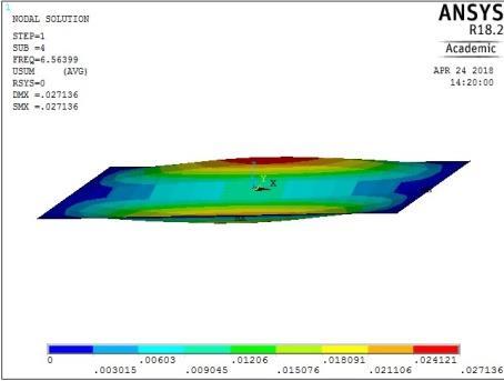
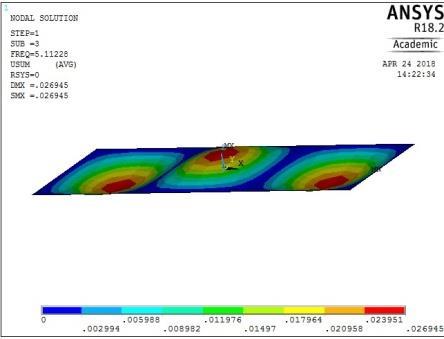
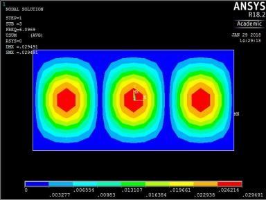
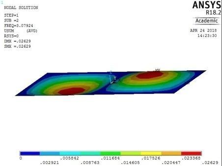
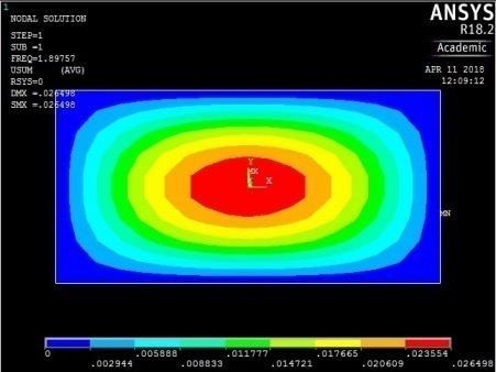
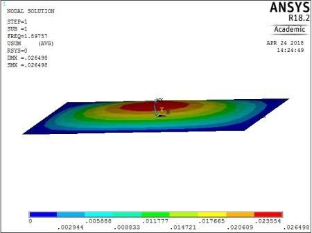
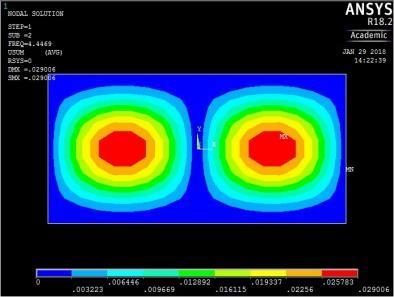
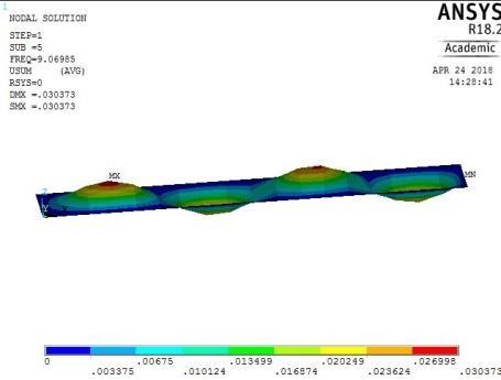
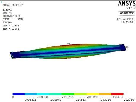
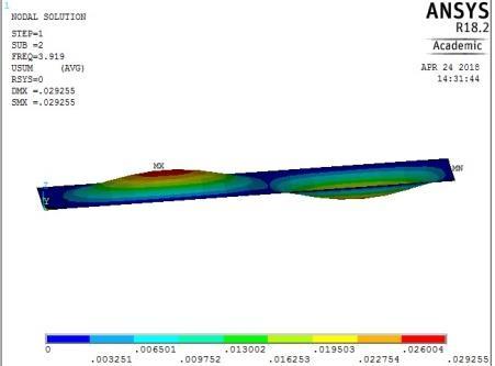
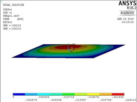
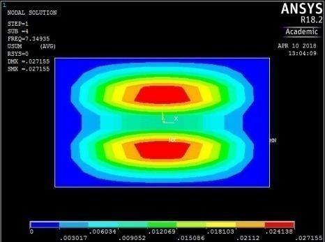
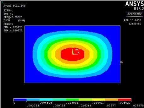
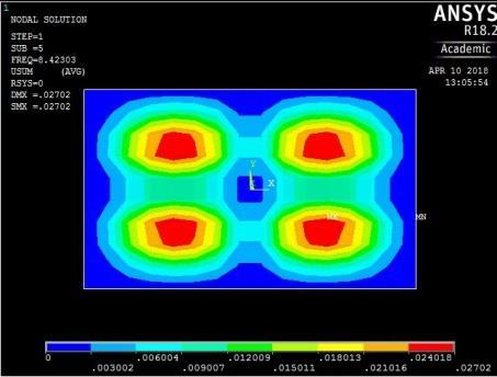
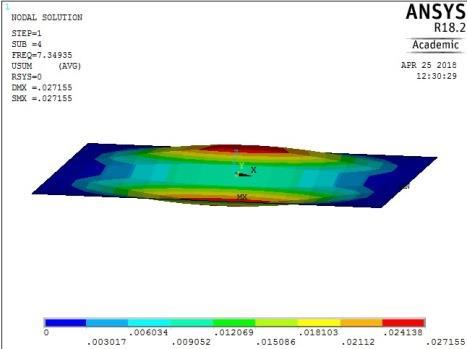
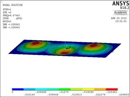
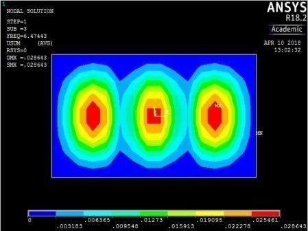
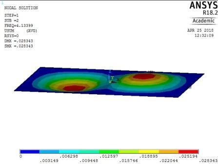
Modal analyses of rectangular reinforced concrete slabs of aspect ratios 0.5, 0.6, 0.7, 0.8, 0.9, and 1.0 were performed with a combination of clamped and simply supported boundary conditions using ANSYS software. As mentioned earlier, the slabs were split into 18 × 9 elements along the length and width of the plates. The output of the computations for all round simply supported plate with aspect ratio of 0.5 is shown in the pictorial representation of the mode shapes in Figure 13-16. From these figures, the following observations on the trend of mode shapes can be made:
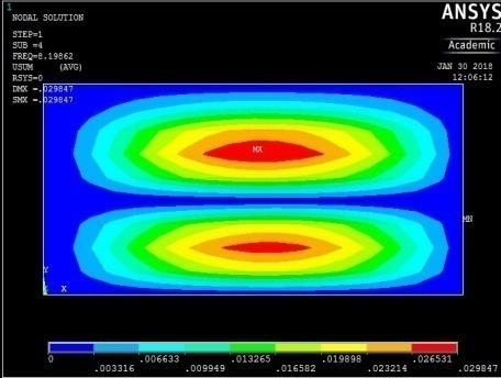
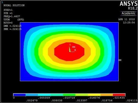
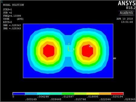
From Figures 13, 14, 15 and 16, it can be seen that plates with aspect ratio of 0.5 exhibited different mode shapes depending on their edge restraints. The plate with SSSS edge restraints with aspect ratio of 0.5 exhibited waveline mode shapes in the sequence of transverse vibration along the centroidal longitudinal axis for the first three frequencies, followed by transverse vibration along the centroidal transverse axis for the fourth frequency and then a torsional vibration in two centroidal diagonal axes. The first frequency exhibited one peak at the centre of plate, the second and third had two and three peaks symmetrically located about the centre. The fourth frequencies were associated with two peaks in the transverse axis equidistant from the centre while the fifth frequency had a peak frequency in the centre of each quadrant of the plate
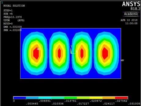
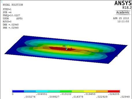
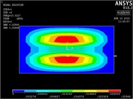
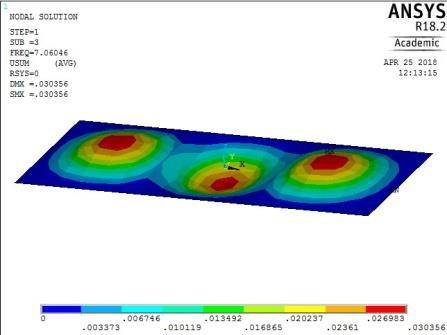
The plate with rigid restraints on all edges (Figure 14) exhibited a similar trend in mode shape variation for the first four frequencies. However, the fifth frequency yielded a transverse vibration with four peaks in the longitudinal axis. There was no torsional vibration.
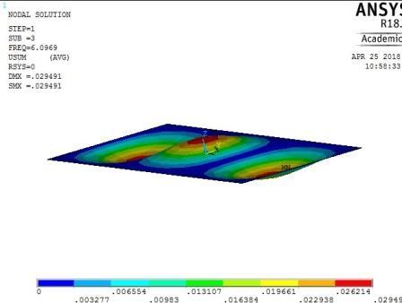
The mode shapes for the plate with CSCS edge restraint (Figure 15) were characterized by transverse vibration along the longitudinal axis for the first four frequencies followed by a transverse vibration in the centroidal transverse axis for the fifth frequency.
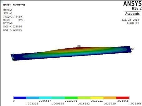
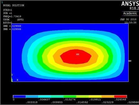
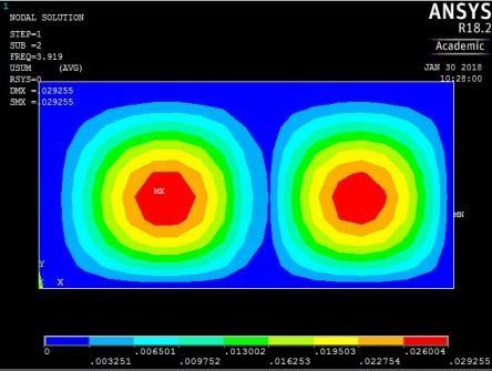
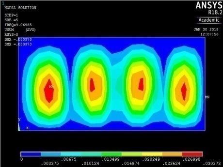
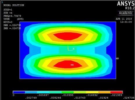
The plate with CCSS edge restraint (Fig. 16) had mode shapes similar to those of the rigidly fixed plate with CCCC edge conditions. The similarity between the behaviour of the plate with CCCC and CCSS restraints was observed earlier as their maximum and minimum frequencies were close in magnitude.
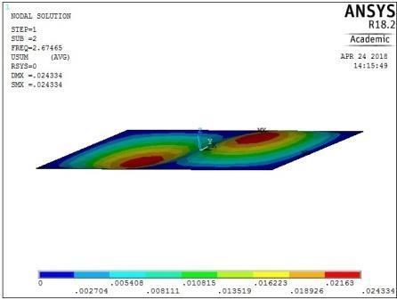
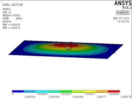
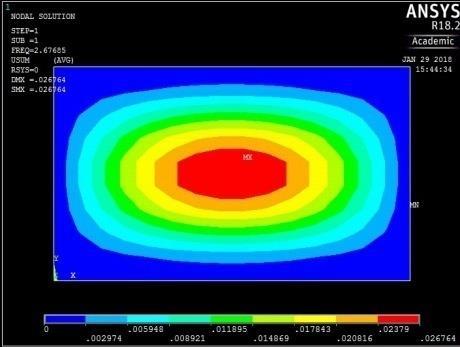
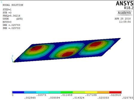
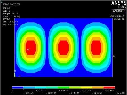
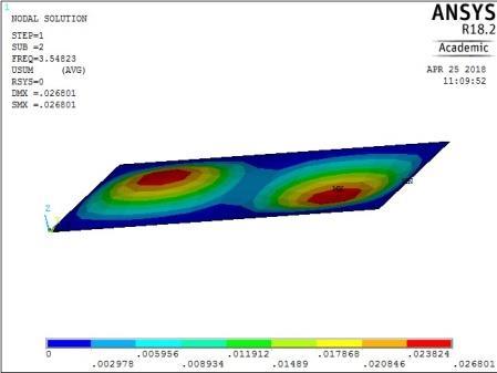
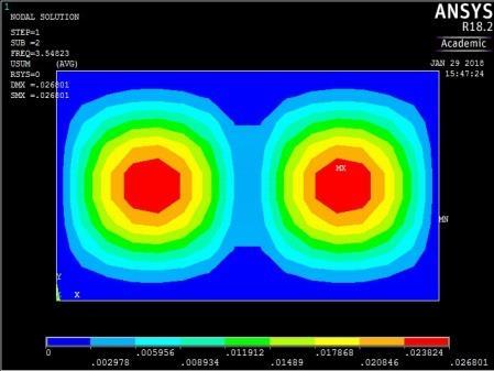
The mode shapes for plates with aspect ratio of 0.6 are presented in Appendix from where it can be observed that all the plates exhibited similar mode shapes of wavelike variation with a sequence of transverse vibration along the centroidal longitudinal axis for the first three frequencies followed by transverse vibration along the centroidal transverse axis and a torsional vibration along the diagonal axes. It follows that the mode shapes of the plates with higher aspect ratios tend towards those of an all round simply supported boundary restraint with aspect ratio of 0.5.
International Journal of Civil and Structural Engineering Research ISSN 2348-7607 (Online) Vol. 6, Issue 2, pp: (207-226), Month: October 2018 - March 2019, Available at: www.researchpublish.com
1st vibration mode ꙍ1 = 11.922972 rad/sec
0.02
0.01
0
0.02
0
0.03 0 10 20 -0.04
2nd vibration mode ꙍ2 = 19.347184 rad/sec
-0.02
0.02
0
-0.02
0.04 0 10 20 30 -0.04
3rd vibration mode ꙍ3 = 32.121528 rad/sec
0.02
0
-0.02
0.04 0 20 40 60 -0.04
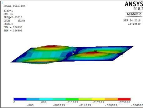

4th vibration mode ꙍ4 = 41.242828 rad/sec
5th vibration mode ꙍ5 = 47.991598 rad/sec
0.02
0
0.04 0 10 20
-0.02
0.04 0 10 20 -0.04
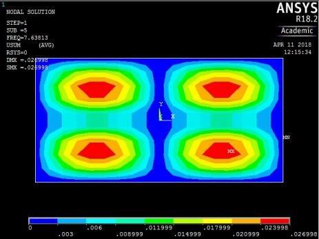
Figure 13: The first five mode shapes of SSSS plate (aspect ratio = 0.5)
1st vibration mode ꙍ1 = 23.749812 rad/sec
0.02
0.01
0
0.02
0
0.03 0 10 20 -0.04
2nd vibration mode ꙍ2 = 30.991183 rad/sec
-0.02
0.02
0
0.04 0 10 20 30 -0.04
3rd vibration mode ꙍ3 = 44.362430 rad/sec
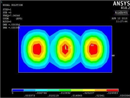
-0.02
4th vibration mode ꙍ4 = 62.976366 rad/sec
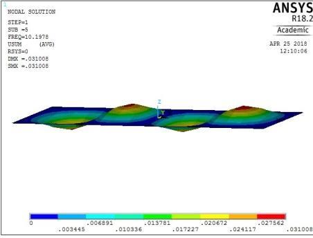

5th vibration mode ꙍ5 = 64.075924 rad/sec
0.02
0
0.04 0 20 40 60 -0.04


-0.02
0.02
0
0.04 0 50 100
-0.02
0.04 0 10 20 -0.04
Figure 14: The first five mode shapes of CCCC plate (aspect ratio = 0.5)

International Journal of Civil and Structural Engineering Research ISSN 2348-7607 (Online) Vol. 6, Issue 2, pp: (207-226), Month: October 2018 - March 2019, Available at: www.researchpublish.com
1st vibration mode ꙍ1 = 22.951848 rad/sec

0.02
0.01
0
0.02
0
0.03 0 10 20 -0.04
2nd vibration mode ꙍ2 = 27.940697 rad/sec
-0.02
0.02
0
0.04 0 10 20 30 -0.04
3rd vibration mode ꙍ3 = 38.307952 rad/sec
-0.02
4th vibration mode ꙍ4 = 54.907500 rad/sec
5th vibration mode ꙍ5 = 62.567959 rad/sec
0.02
0
0.04 0 20 40 60 -0.04

-0.02
0.02
0
0.04 0 10 20
-0.02
0.04 0 50 100 -0.04


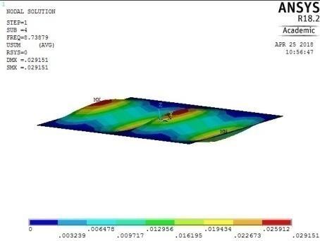

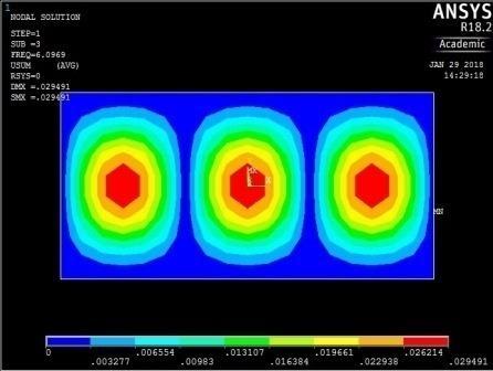

Figure 15: The first five mode shapes of CSCS plate (aspect ratio = 0.5)

International Journal of Civil and Structural Engineering Research ISSN 2348-7607 (Online) Vol. 6, Issue 2, pp: (207-226), Month: October 2018 - March 2019, Available at: www.researchpublish.com
0.02
0.01
1st vibration mode ꙍ1 = 17.179485 rad/sec

0
2nd vibration mode ꙍ2 = 24.623803 rad/sec
0.02
0
0.03 0 10 20 -0.04
-0.02
0.02
0
0.04 0 10 20 -0.04
3rd vibration mode ꙍ3 = 37.843625 rad/sec

-0.02
4th vibration mode ꙍ4 = 51.513323 rad/sec
5th vibration mode ꙍ5 = 56.987234 rad/sec
0.02
0
0.04 0 20 40 60 -0.04
-0.02
0.02
0
0.04 0 50 100
-0.02
0.04 0 10 20 -0.04
Figure 16: The first five mode shapes of CCSS plate (aspect ratio = 0.5)
International Journal of Civil and Structural Engineering Research ISSN 2348-7607 (Online) Vol. 6, Issue 2, pp: (207-226), Month: October 2018 - March 2019, Available at: www.researchpublish.com
4. CONCLUSION AND RECOMMENDATIONS
4.1 Conclusion
In this work, the characteristic orthogonal polynomials have been applied to the Rayleigh-Ritz method for plates with four different boundary configurations. These include plates clamped on two adjacent edges and simply supported on the other two (CCSS), plates clamped on two opposite edges and simply supported on the other two opposite edges (CSCS), plate simply supported on all edges (SSSS), and plates clamped on all edges (CCCC). Based on the results obtained, it can be concluded that the model developed present an efficient technique for the evaluation and prediction of the fundamental frequencies and mode shapes of orthotropic plates with varying boundary conditions and aspect ratios.
Specifically, the maximum and minimum frequencies of 23.95 and 9.43 rad/sec were obtained for plates with all round rigid fixity for aspect ratios of 0.5 and 1.0 respectively. Plates with CCSS and CSCS edge restraints yielded intermediate values of fundamental frequencies with the plate with similar restraints on contiguous sides showing the lesser values. It is noteworthy that plate clamped on opposite side and simply supported on the opposite side gave a maximum frequency almost equal to that for all round clamped plate. Rectangular plates with simply supported edges showed the least values of maximum and minimum of 12.08 and 5.17 rad/sec for aspect ratio of 0.5 and 1.0 respectively. The model output was in close agreement with those of other researchers and standard computer software to about 99 percent accuracy.
The mode shapes for plates with aspect ratio of 0.5 significantly depend on the boundary conditions of the plate. For allround simply supported plate, the mode shape represented a sequence of transverse vibration along the longitudinal axis for the first three frequencies, followed by transverse vibration along the transverse axis for the fourth frequency and torsional vibration for the fifth. Mode shapes for plates with other boundary conditions were characterised by slight changes in the sequence but without the torsional mode. The mode shapes for plates with aspect ratio of 0.6 tend to follow the trend for simply supported plate irrespective of boundary condition.
4.2 Recommendations
Further studies are recommended on application of the developed model for plates with other boundary conditions, varying thickness and plate on elastic foundation.
REFERENCES
[1] Timoshenko, S.P. and Krieger, S. W. (1959). Theory of Plates and Shells. Tokyo: McGraw-Hill.
[2] Hearmon, R. F. S. (1959). The Frequency of Flexural Vibration of Rectangular Orthotropic Plates with Clamped or Supported Edges. Journal of Applied Mechanics, Vol. 26, pp. 537– 40.
[3] Bazely, N. W., Fox, D. W. and Stadter, J. T. (1965).Upper and Lower Bounds for Frequencies of Rectangular Clamped Plates. Applied Physics Laboratory, Technical Memo, TG- 626. The John Hopkins University, Baltimore.
[4] Marangoni, R.D., Cook, L. M. and Basavanhally, N. (1978). Upper and Lower Bounds to the Natural Frequencies of Vibration of Clamped Rectangular Orthotropic Plates. International Journal of Solids and Structures, Vol.14, No. 6, pp. 11–23.
[5] Yu, S. D. (2009). Free and Forced Flexural Vibration Analysis of Cantilever Plates with Attached Point Mass. Journal of Sound and Vibration, Vol. 321, pp. 270–285.
[6] Rossi, R. E., Bambill, D. V. and Laura, P. A. (1998). Vibrations of a Rectangular Orthotropic Plate with a Free Edge a Comparison of Analytical and Numerical Results. Ocean Engineering, Vol. 25, No. 7, pp. 521–527.
[7] Chen, Y. Z. (1998). Evaluation of Fundamental Vibration Frequency of an Orthotropic Bending Plate by Using an Iterative Approach. Computational Methods and Applied Mechanical Engineering, Vol. 161, pp. 289–296.
[8] Huang, M., Ma, X. Q., Sakiyama, T., Matuda, H. and Morita, C. (2005). Free Vibration Analysis of Orthotropic Rectangular Plates with Variable Thickness and General Boundary Conditions. Journal of Sound and Vibration, Vol. 288, pp. 931–955.
[9] Chalak, H. D., Chakrabarti, A., Sheikh, A. H., and Iqbal, M. A. (2014). C0FE Model Based On HOZT for the Analysis of Laminated Soft Core Skew Sandwich Plates: Bending and Vibration. Applied Mathematical Modelling, Vol. 38, pp. 1211–1223.
[10] Bayat, M., Pakar, I. and Bayat, M. (2011). Analytical Study on the Vibration Frequencies of Tapered Beams. Latin American Journal of Solids and Structures, Vol. 8.2, pp. 149–162.
0.02
0.01
0
0.02
0
0.03 0 10 20 -0.04
-0.02
0.02
0
0.04 0 10 20 -0.04
-0.02
0.02
0
0.04 0 20 40 60 -0.04
-0.02
0.02
0
0.04 0 10 20
-0.02
0.04 0 10 20 -0.04
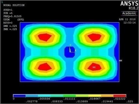
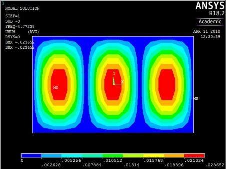
5th vibration mode ꙍ5 = 37.16566941 rad/sec Figure A1: The first five mode shapes of SSSS plate (aspect ratio = 0.6)

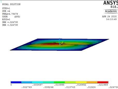
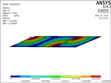

0.02
0.01
1st vibration mode ꙍ1 = 17.82849370 rad/sec
0
0.02
0
0.03 0 10 20 -0.04
2nd vibration mode ꙍ2 = 25.97468806 rad/sec
-0.02
0.02
0
0.04 0 10 20 -0.04
3rd vibration mode ꙍ3 = 40.67985495 rad/sec
-0.02
4th vibration mode ꙍ4 = 46.1776421 rad/sec
0.02
0
0.04 0 20 40 60 -0.04
-0.02
0.02
0
0.04 0 10 20
-0.02
0.04 0 10 20 -0.04
5th vibration mode ꙍ5 = 52.92326984 rad/sec
Figure A2: The first five mode shapes of CCCC plate (aspect ratio = 0.6)

1st vibration mode ꙍ1 = 16.763915 rad/sec
0.02
0.01
0
0.02
0
0.03 0 10 20 -0.04
2nd vibration mode ꙍ2 = 22.29399811 rad/sec
-0.02
0.02
0
0.04 0 10 20 -0.04
3rd vibration mode ꙍ3 = 33.69169625 rad/sec
-0.02
4th vibration mode ꙍ4 = 45.66493418 rad/sec
0.02
0
0.04 0 20 40 60 -0.04

-0.02
0.02
0
0.04 0 10 20
-0.02
0.04 0 10 20 -0.04
5th vibration mode ꙍ5 = 50.87809302 rad/sec
Figure A3: The first five mode shapes of CSCS plate (aspect ratio = 0.6)




0.02
0.01
1st vibration mode ꙍ1 = 7.596269446 rad/sec
0
0.02
0
0.03 0 10 20 -0.04
2nd vibration mode ꙍ2 = 15.33851197 rad/sec
-0.02
0.02
0
0.04 0 10 20 -0.04
3rd vibration mode ꙍ3 = 23.26475024 rad/sec
-0.02
0.02
0
0.04 0 10 20 -0.04
4th vibration mode ꙍ4 = 29.12759045 rad/sec
-0.02
0.02
0
0.04 0 10 20
-0.02
0.04 0 20 40 60 -0.04
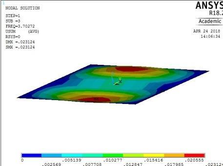


5th vibration mode ꙍ5 = 30.5601567 rad/sec
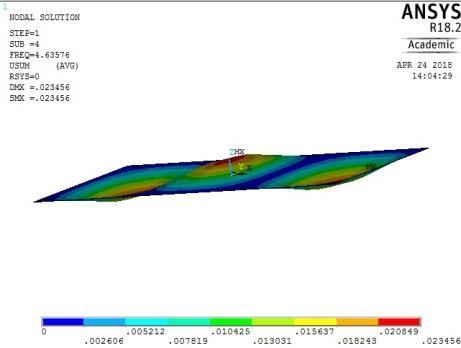
Figure A5: The First Five Mode Shapes of SSSS Plate (aspect ratio = 0.7)

