International Journal of Civil and Structural Engineering Research ISSN 2348-7607 (Online) Vol. 10, Issue 2, pp: (10-33), Month: October 2022 - March 2023, Available at: www.researchpublish.com
Performance and strengthening of the circular R.C. Columns with high slenderness ratios using GFRPExternal Wrapping
Nehal M. Ayash 1, Abeer Fathy 2 , Ata El-kareim Shoeib31 Assistant professor Civil Engineering Department, Faculty of Engineering at Mataria, Helwan University, Cairo 11718, Egypt
2 M.Sc. student Civil Engineering Department, Faculty of Engineering at Mataria, Helwan University, Cairo 11718, Egypt
3Professor of Reinforced concrete structures, Civil Engineering Department, Faculty of Engineering at Mataria, Helwan University, Cairo 11718, Egypt
DOI: https://doi.org/10.5281/zenodo.7330504
Published Date: 17-November-2022
Abstract: The research investigated the behavior of reinforced concrete (RC) columns which have high slenderness ratios, and this strengthens with GFRP wrapping laminate. Twelve RC columns having a circular cross-section with various slenderness ratios (H/D) 16, 18, 20, and 22 were tested experimentally under concentric axial load. The first group of columns was non-strengthened as control. Secondly, the fully strengthened with GFRP wrapping laminates in the hoop direction and thirdly, the partially strengthened with GFRP wrapping laminates in the hoop direction were tested. Then the numerical models were developed and validated with the experimental results. The numerically developed model was implemented to demonstrate the effect of changing the orientation of the GFRP laminates, in addition, the effect of applied the eccentric axial load on the capacity of the strengthened slender columns were explored. Lastly, the experimental results for unconfined and FRP-confined columns are compared with ECP and ACI codes provisions. It can be concluded that increasing the slenderness ratio of columns causes a reduction in the ultimate axial load, axial deformation arising from decreasing the column stiffness but increasing the lateral deformation. Fully wrapped enhanced the lateral deformation of slender columns by reducing them by 0.8 to 0.55 when compared to partially wrapped as the slenderness ratio increased from 16 to 22. The column capacity predicted by ECP is more conservative than ACI for unconfined and confined slender columns. GFRP hoop strengthening barely increased the resistance for slender columns, while GFRP strengthening in the longitudinal direction contributes to their capacities.
Keywords: circular columns; GFRP; Slenderness ratio; ductility index; initial load eccentricity.
I. INTRODUCTION
The usage of slender columns is widespread nowadays due to the rapid increase in the number of high-rise buildings resulting from the architectural development of the age. The slenderness ratio is one of the crucial parameters that affect the behavior of slender RC columns. The slenderness ratio can be defined as the ratio of the column effective length to the least of the radius of gyration of the cross-section. In addition, it can be defined by the ratio of effective length to the smallest dimension of the cross-section. Columns with higher slenderness ratios are vulnerable to instability buckling failure resulting from the secondary moment effect. This effect led to a significant reduction in their ultimate resistance compared to that of short columns. ACI-318 and ECP-203 state limits for slender columns, the slenderness ratio (KH/r) is not exceeded 40 for ACI-318 and is not exceeded 70 for ECP-203, where H is unsupported column height, r is the crosssection radius of gyration and K is constant that reflect the column end conditions. Increasing the resistance of the slender columns is required strengthening to withstand the excessive loads. One solution for strengthening elements is using fiber-reinforced polymer wrapping (FRP) for improving columns confinement.
International Journal of Civil and Structural Engineering Research ISSN 2348-7607 (Online) Vol. 10, Issue 2, pp: (10-33), Month: October 2022 - March 2023, Available at: www.researchpublish.com
Many previous studies tended to study the behavior of short R.C. columns under axial concentric or eccentric force and with or without strengthening. Pan, J. L. et al. (2007) [1] tested six columns under axial loading. The specimens have a rectangular with a slenderness ratio from 4.5 to 17.5. The CFRP wrapping was used in strengthening. They found that the FRP strengthening effect is inversely proportional to the column's slenderness ratio. When the slenderness ratio is greater than 10, the columns are failed due to buckling and the FRP cannot be used fully due to its rupture after the peak load. Fitzwilliam, J., & Bisby, L. A. (2010) [2] tested eighteen circular columns under eccentric axial load with various slenderness and CFRP strengthening schemes. The slenderness ratio was varied from 10 to 35. They found that increasing the slenderness caused reducing in load capacity but increasing in lateral deflection. The higher levels of CFRP confinement are s by the slenderness. Strengthening the slender columns with hoop wraps only caused a reduction in flexural rigidity due to increasing the second-moment effects. Strengthening with longitudinal wraps can improve the behavior of slender columns due to its contribution to increasing the tangent flexural rigidity of the column. Soliman, A. E. K. S. (2011) [3] tested six columns filled in plastic tubes and without steel reinforcement. Tested columns have slenderness ratios ranging from 10 to 17.5. It was found that columns with lower slenderness ratios fail in diagonal shear failure arising from the plastic tube failure. The columns with higher slenderness ratios experienced tensile failure due to the excessive increase in the horizontal displacements at the column mid-height that caused the concrete crushed on one side and cracked on the other one. Chikh N. et al. (2012) [4] studied the effect of both the slenderness and the strengthening ratios for the column specimens confined with CFRP strips. Eighteen column specimens having slenderness ratios 2, 5, and 6.5 and strengthened with 0, 1, and 3 layers are studied. They concluded that increasing the column's slenderness led to a change in the failure location from its central zone to a lower one and a decrease in the CFRP ruptured. Raval, R., & Dave, U. (2013) [5] tested fifteen columns under axial load, nine columns were non-strengthened, and the rest six columns were strengthened with one layer of GFRP. The slenderness ratios are 5.8, 6.67, and 9 for the different cross-sections as circular, square, and rectangular columns, respectively. They found that the GFRP wrapping for circular columns can carry a load more than the square and rectangular columns. Control and strength-ened circular columns get higher axial deformation than rectangular columns. The axial deformation for wrapped square and circular columns is less than that for rectangular columns. Saravanan J. et al. (2014) [6] studied the effect of the slenderness ratio on the behavior of high-strength concrete circular columns wrapped with UDCGFRP wraps. They tested twelve specimens having slenderness ratios ranging 8, 16, 24, and 32; one column for each slenderness ratio was kept without any wrapping, and the remaining columns were wrapped with different wraps thicknesses; 3 and 5 mm. They deduced that the column's ultimate capacity is decreased by increasing the slenderness ratio. Increasing the thickness of the wraps led to an increase in the ultimate strength. The axial strain and deflection ductility for unwrapped columns are more sensitive to slenderness ratio than wrapped ones. Dundar, C. et al., (2015) [7] tested sixteen columns which are made from conventional reinforced concrete and steel fiber reinforced concrete and confined with CFRP under both vertical load and biaxial mo-ments. They observed the brittle behavior of the conventional reinforced concrete columns without CFRP wraps. Adding of steel fibers in concrete developed the column ductility and deformability. The lateral stiffness is achieved for the plain and steel fiber reinforced concrete columns strengthened with CFRP sheets. CFRP sheets have improvement effect on the load capacity of both conventional and steel fiber reinforced concrete columns, while the steel fibers in concrete have no enhancement effect on the load capacity compared with conventional concrete. Nadaf, F., &Biradar, P. (2015) [8] tested six slender reinforced high-performance concrete ranging from 60 MPa to 100 MPa columns under eccentric axial load. The column's slenderness ratio was equal to 15. They observed less deformation at the mid height due to the brittle behavior for HPC column with highest concrete compressive strength. Decreasing the spacing of lateral ties at both the ends up to certain distance had influenced to resist the shear arising from uniaxial bending. Maranan, G. B., et al. (2016) [9] tested eight geopolymer concrete circular columns reinforced with GFRP bars under concentric axial loading. Six short columns (L/r=8) sub-divided as one column without transverse reinforcement; three columns with circular hoops spaced at 50, 100, and 200 mm; and two columns with spirals spaced at 50 and 100 mm. In addition, two slender columns (L/r =16) transversely rein-forced with hoops and spirals both spaced at 100 mm were tested. They found that the slender columns exhibited higher deformation compared to the short columns due to their lateral movement. The spiral-confined columns get higher ductility index and confinement efficiency compared to the hoop-confined ones. Gopal, S. R. (2017) [10] tested eighteen circular columns under eccentric loading: six columns were plain Concrete filled in steel tube; six columns with fiber reinforced concrete filled in steel tube and six columns were empty steel tubular Columns with slenderness ratio varied from 11 to 28. The columns were loaded with eccentric axial load. He found that bucking failure was due to concrete crushing and steel yielding in the compression side at mid-height of the column. Fiber reinforced concrete filled columns showed stiff behavior at largest slenderness ratio and the strength increased by 15% more than plain concrete filled columns. Farooq, H., et al. (2018) [11] tested six columns under axial loading divided equally as unconfined, strengthened with steel strips and strengthened with a steel jacket. They noticed
Research Publish Journals
International Journal of Civil and Structural Engineering Research ISSN 2348-7607 (Online) Vol. 10, Issue 2, pp: (10-33), Month: October 2022 - March 2023, Available at: www.researchpublish.com
that the axial resistance is enhanced by 1.54 times when using steel strips and by 2.38 times when using the steel jacketing; moreover, the cracking load is increased by 1.5 to 2.66 times for strips and jacketing, respectively. Lu, Y., et al. (2018) [12] tested nine specimens of slender columns under axial load: one as a control specimen without strengthening and eight specimens with heights ranging between 1240 and 2140 mm strengthened with steel tube jacketing technique. They noticed that the outer steel tube provided confinement to slender RC columns. Confinement with steel tube; the failure mode of slender RC columns was changed from brittle failure (concrete peel-off) to ductile failure (global bending). The strengthening effect of steel tube jacketing decreased with increasing L/D and D/t ratio but showed little variations for different SCC strength. Montaser, W., et al. (2019) [13] tested three groups, each group consists of 5 square columns. They found that the width of CFRP strips preferred to be not less than spacing of CFRP strips. Increasing the CFRP ratio increased the stirrups efficiency. Xing, L., Lin, G., & Chen, J. F. (2020) [14] studied behavior of circular RC columns confined with FRP jacketing loaded eccentrically. Ten columns tested; divided into three groups. They noticed that the longitudinal steel bars were yielded before the ultimate axial load was reached for all confined columns. The failure for unconfined column was sudden due to concrete crushing and spalling near mid height on the compression side; the longitudinal steel bars are not yielded prior to concrete crushing, and very small lateral displacements had developed at failure. The ultimate load capacity was directly proportional to the FRP thickness and inversely proportional to the initial load eccentricities and slenderness. The mid-height lateral displacement increased with increasing the slenderness. Hu, Z., Li, Q., Yan et.al (2021) [15] tested 12 columns; half the columns were unwrapped, and the other half were wrapped. All the columns have a diameter of 200 mm and slenderness ratios of 12, 20, 32, 40, 48, and 56. They concluded that the loading resistance decreased by increasing the slenderness ratio of the column. The influence of the slenderness ratio in reducing the ultimate load capacity was greater for wrapped column than unwrapped ones. Cassese P. et.al (2021) [16] tested four specimens which had a square cross-section with 1000 mm height. One specimen was a nonstrengthened and three columns strengthened by external HPFRC jacketing. The test outcome that a significant improvement of the performance for the strengthened columns, especially for higher values of eccentricity. Miao, K et.al (2021) [17] carried out test on twenty-four specimens. Three of them are concrete-filled steel tube, three concrete-filled grooved steel tube and eighteen concrete-filled grooved CFRP tube. They found that the bearing capacity of the grooved structure was improved the mechanical mechanism of the column. Koosha Khorramian and Pedram Sadeghian (2021) [18] conducted the tests in two phases under com-pression loads. Phase I was conducted on eighteen circular cylinders strengthened by longitudinally by CFRP strips, trans-versely by GFRP wrappings, or a hybrid of both. Phase II was conducted on three slender columns with 3048 mm height as phase I. In phase I, it was observed that by applying wraps on longitudinal direction, the failure mode changed from buckling/debonding to crushing with increasing the column capacity. The usage of wrapping without longitudinal laminates was more effective than the proposed hybrid system. In phase II, the hybrid system enhanced the wrapping system for slender columns by increasing by 52%, 105%, and 94% for axial capacity, flexural capacity, and lateral displacement, respectively. Tin, H.-X. et.al (2022) [19] tested fourteen rectangular columns under uniaxial and biaxial eccentric loading, including five controlled columns and nine strengthened with CFRP. The CFRP-strengthened columns were partially and fully confined with one layer in vertical sheets at four sides. Under the uniaxial eccentric load, the partially and fully CFRP-confinement enhanced the load capacity by 19% and 33% at eccentricity (e/h) of 0.125, respectively, and 8% and 11% at e/h = 0.25, respectively. For the partially CFRPwraps columns, the load-carrying capacities were improved by 19% and 31%, respectively subjected under biaxial eccentric load with e/h = 0.125 and 0.25. Yahiaoui et al. (2022) [20] examined 48 circular columns strengthening by GFRP wrapping under pure compression load: containing different proportion of fibers ranging from 0.3 to 1.2, with different concrete strengths varying from 8.5 to 25 MPa and with different confinement levels (2, 4 and 6 layers). They found that the confinement effect with GFRP has an enhancement effect for concrete containing glass fiber (GFCC). The number of GFRP layers shows a positive behavior on the ultimate stress and strain
II. RESEARCH SIGNIFICANCE
The usage of columns with slenderness ratio exceeded the maximum limits is necessary like in high-rise buildings and bridges. This type of slender columns is more subjected to buckling and fail at lower loads compared to ordinary slender columns. According to ECOP-203, the maximum slenderness ratio must not exceed the limits as (kH/r) more than 70 or (H/D) more than 18. The strengthening of these types of columns using FRP can be improve the structural service performance and increase the ultimate capacity of concrete structures. By reviewing the past studies on strengthening of long columns using FRP, it can be concluded that there is a research gap on the behavior of strengthened slender columns that their slenderness ratio exceeded the code limitations. Thus, this study aims at investigating the behavior and the effect of strengthening slender columns using GFRP wraps. In addition, the effect of load eccentricity and the design codes is tackled.
International Journal of Civil and Structural Engineering Research ISSN 2348-7607 (Online) Vol. 10, Issue 2, pp: (10-33), Month: October 2022 - March 2023, Available at: www.researchpublish.com
III. EXPERIMENTAL WORKS
Twelve slender circular RC columns specimens with four different heights will be tested under concentric axial load; these four heights are then partially and fully strengthened with GFRP wraps. As listed in Table I, three groups of RC columns are tested; each group will include four different heights of RC columns with the same cross-section area. These Three groups of slender RC columns will be distinguished as following: The first group (C) will include four different heights of circular slender RC column with slenderness ratios (kH/r) ranged from 64 to 88 where r = 0.25D with slenderness ratios (H/D) ranged from 16 to 22 (D = column diameter). The second group (P) will include the same four columns in group one but partially wrapped with GFRP. The third group (F) will include the same four columns in group one but fully wrapped with GFRP.
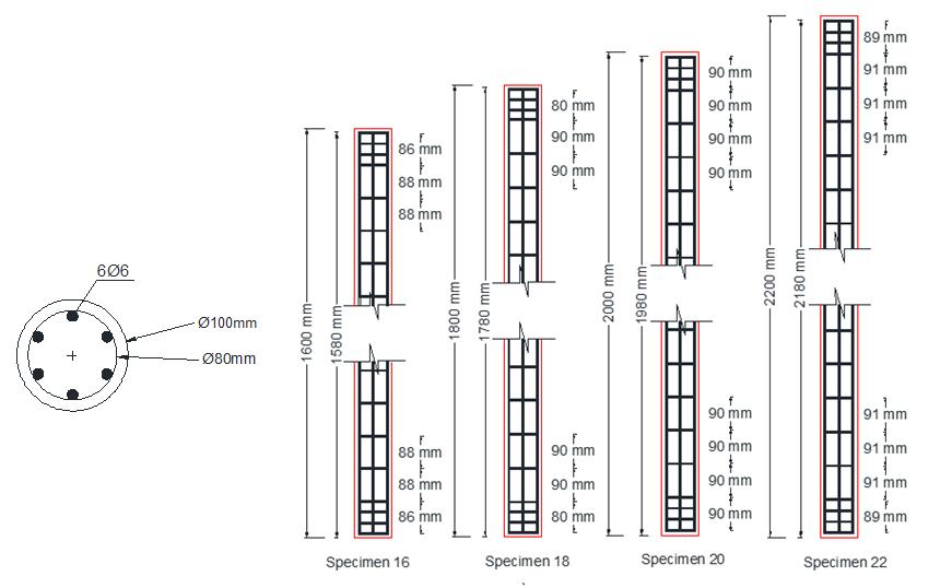
The main reinforcement of those circular columns is 6 Ф 6 mild steel bars. The reinforcement ratio is 2.16% of the gross cross section area. The transverse reinforcement is Ф 6 mild steel hoops needed for the confinement of concrete. The spacing between these circular hoops is about 90 mm along the height of the column and the spacing is decreased at the column’s top and bottom to avoid the concentration of stresses. Figure 1 shows the concrete dimension and reinforcement of the test specimens.
For the partially strengthened RC circular slender columns with GFRP wraps, the wrapping laminate is 0.168 mm thick, 50 mm wide along the height of the column and with spacing 200 mm. While for the fully strengthened slender columns, the wrapping laminate is along the full height of the column, 0.168 mm thick and 365 mm long to ensure the overlapping of the laminate around the surface area of the column as seen in Figure 2.
Table I Description for tested columns
Group Specimen ID Diameter (D) (mm) Height (H) (mm)
Control C
Partially wrapped P
Fully wrapped F
Slenderness ratio (H/D)
Slenderness ratio (kH/r)
1600 16 64 C18 1800 18 72 C20 2000 20 80 C22 2200 22 88
C16 100
P16 1600 16 64 P18 1800 18 72 P20 2000 20 80 P22 2200 22 88
F16 1600 16 64 F18 1800 18 72 F20 2000 20 80 F22 2200 22 88
Figure 1: Concrete dimension and reinforcement details of the test specimens.
(a) (b) (c)
Figure 2: The test specimens (a) control C16, C18, C20 and C22 (b) partially wrapped P16, P18, P20 and P22 and (c) fully wrapped F16, F18, F20, F22.
A. Properties of Material
The cubic compressive strength of concrete after 28-day was 42 MPa, having the maximum aggregate size as 10 mm and the water content ratio is equal to 0.5. Table II listed the mixing proportions for cubic meter of concrete. The additive used in concrete mix was R-2004 provided by Sika Egypt for Construction Chemicals S.A.E that is retarding the set of concrete. The propose of adding this additive to the concrete mix was to produce the free-flowing concrete and thus increasing its workability to ease pouring of concrete in the 10 mm PVC pipes with heights ranging between 1600 mm to 2200 mm and preventing the segregation. The recommended Dosage for the additive is 0.6 - 2.5 % of the weight of cement. The 6 mm diameter of mild steel bars were used for both longitudinal bars and stirrups. Table III showed the properties of reinforced steel bars. The glass fiber-reinforced- polymer (GFRP) sheets by SIKA-EGYPT were used for strengthening. The SikaWrap with grade 430G is a unidirectional woven E-GFRP. The SIKADUR-330 epoxy is used. The mechanical properties of fiber sheets and epoxy provided by SIKA-factory are listed in Table IV and Table V.
Table II: The mixing proportions of cubic meter concrete.
Coarse aggregate 1044 kg Fine aggregate 696 kg Water 180 Lr. Cement 360 kg Additive “R-2004” 8.4 Lr.
Table III: The properties of steel reinforcement
Bar diameter Yielding strength Yielding strain Ultimate strength 6 mm 240 (N/mm2) 0.002 350 (N/mm2)
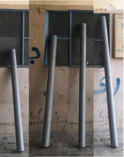
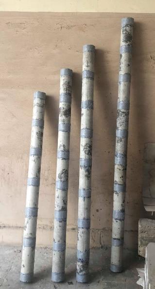
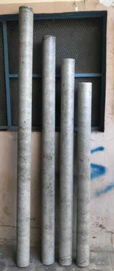
Table IV: Mechanical properties for SIKAWRAP-430 G
Density 2.56 g/cm3
Tensile Strength 2500 N/mm2
Modulus of Elasticity 72000 N/mm2
Elongation 0.0208 Thickness 0.168 mm
International Journal of Civil and Structural Engineering Research ISSN 2348-7607 (Online) Vol. 10, Issue 2, pp: (10-33), Month: October 2022 - March 2023, Available at: www.researchpublish.com
Table V: Mechanical properties for SIKADUR- 330
Density
1.30 kg/L
Flexural Modulus of Elasticity 3800 N/mm2
Tensile Modulus of Elasticity 4545 N/mm2
Tensile Strength 30 N/mm2
Elongation 0.0066
B. Test setup and measuring devices:
The test was conducted in the reinforced concrete laboratory in faculty of engineering at Helwan University. The test setup for testing the specimens includes a steel frame, two steel plates, loading cell and hydraulic jack used for axial compression; each column specimen was capped at its top and bottom with a steel capping to avoid the concentration of stresses and ensure load transfer among the height of the column. The specimen’s vertical alignment was adjusted using a spirit level. Figure 3 shows the setup for testing.
The vertical and lateral deformations of column specimens was measured by attaching three linear variable distance transducers (LVDT). One was placed vertically at the top to measure the vertical deformation and another two LVDT devices were placed horizontally at 0.25 and 0.5 of the height of the specimens.

IV. EXPERIMENTAL DATA AND DISCUSSIONS
A. Failure modes:
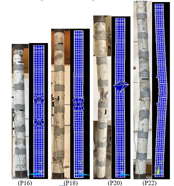
Figure 4 shows all tested column specimens at failure. For control specimens, failures in column specimens of slenderness 16, 18 and 20 were considered as a compression failure while failure in column specimen of slenderness ratio 20 and 22 was considered buckling failure. Compression failure for specimens 16 and 18 happened at the top and bottom ends of the column.
In partially wrapped columns, the specimens P16 and P18 failed when longitudinal cracks initiated near the top or bottom of the column specimen in the weakest zone at the concrete between the GFRP laminates and then propagated causing the
International Journal of Civil and Structural Engineering Research ISSN 2348-7607 (Online) Vol. 10, Issue 2, pp: (10-33), Month: October 2022 - March 2023, Available at: www.researchpublish.com
concrete crushed and cover spalling. Column specimen P20 appeared to have the same failure pattern of P16 and P18 but the failure was noticed to be around the mid height and between the GFRP laminates. Failure modes of specimens P16, P18 and P20 can be described as a compression failure. Specimen P22 failed when the columns experience large horizontal deflections near the failure load which caused horizontal cracks at the tension zone and longitudinal cracks at the compression zone that led to failure by buckling. Buckling failure occurred at the concrete between two GFRP laminates near the mid height of the column specimen.
In fully wrapped column specimens with different studied slenderness ratios, Failure occurred when the additional moments caused the initiation of horizontal cracks in fiber sheets in the tension zone and rupturing of GFRP sheet in the compression zone of the column. Rupture of GFRP sheets occurred by outward pressure force of the crushed concrete and buckled steel bars underneath the GFRP sheets. The buckling mode of failure appeared directly after reaching the peak load. GFRP strengthening in transverse direction nearly failed for long column [1], [3], [10] and [14].
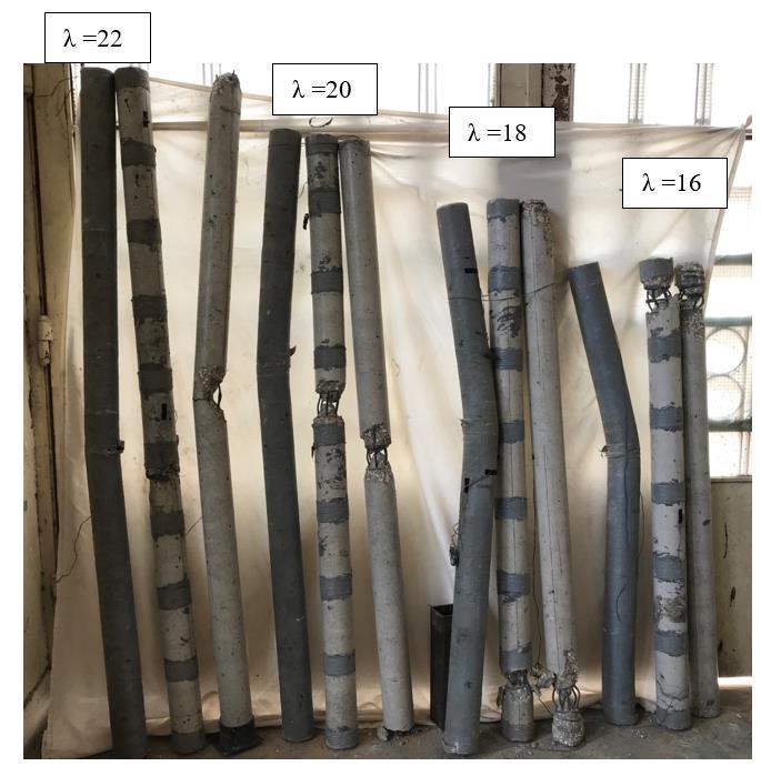
Figure 4: all tested column specimens at failure.
B. Load-vertical deflection relationship and buckling profile:
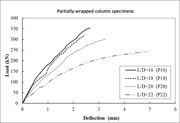
Table VI summarized the test results. Figure 5, 6, 7 and Figure 12 show the load–deflection relations and the buckling profiles for control un-strengthened, partially strengthened and fully strengthened column specimens considering the effect of slenderness ratio.
International Journal of Civil and Structural Engineering Research ISSN 2348-7607 (Online) Vol. 10, Issue 2, pp: (10-33), Month: October 2022 - March 2023, Available at: www.researchpublish.com
Table VI: The test results for all column specimens.
Group Name Specimen ID Ultimate load (Pu) Axial def. (δv) Horizonta l def. (δh) % With respect to slender ratio = 16
Control (C)
Partially wrapped (P)
Fully wrapped (F)
% Strengthened/un -strengthened Failure Mode
kN mm mm Pu δv δh Pu δv δh
C16 359.8 3.3 10
Compression
C18 317.9 2.7 14 88 82 140 Compression
C20 298.2 3.13 19 83 95 190 Buckling C22 246.3 5.15 26 68 156 260 Buckling
P16 375.4 2.65 12 104 80 120 Compression
P18 322.35 2.44 15 86 92 125 101 90 107 Compression
P20 299.89 3.26 20 80 123 167 101 104 105 Buckling
P22 244.92 4.89 26.32 65 185 219 99 95 101 Buckling
F16 371.31 3.515 19 103 107 190 Buckling
F18 324.26 3.123 21 87 89 111 102 116 150 Buckling
F20 300.2 3.148 22 81 90 116 101 101 116 Buckling
F22 243.2 5.02 26.66 65 143 140 99 97 103 Buckling
• Effect of slenderness ratio:
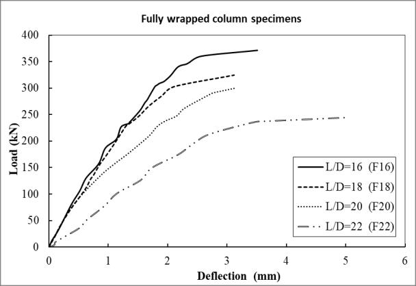
The first comparison is concerned on the response of different slenderness ratio on the columns performance either unstrengthened or strengthened. It can be noted that the column resistance is decreased with increasing the slenderness ratio in control specimens and strengthening either partially or fully with the same ratio [2], [4], [14] and [15] i.e., by increasing the slenderness ratio from 16 to 18 the reduction in load is about 86%, while from 16 to 20 the load reduction is about 81% and from 16 to 22 the reduction in load is about 65%. This is because the stiffness of columns is decreased with increasing the slenderness ratio.
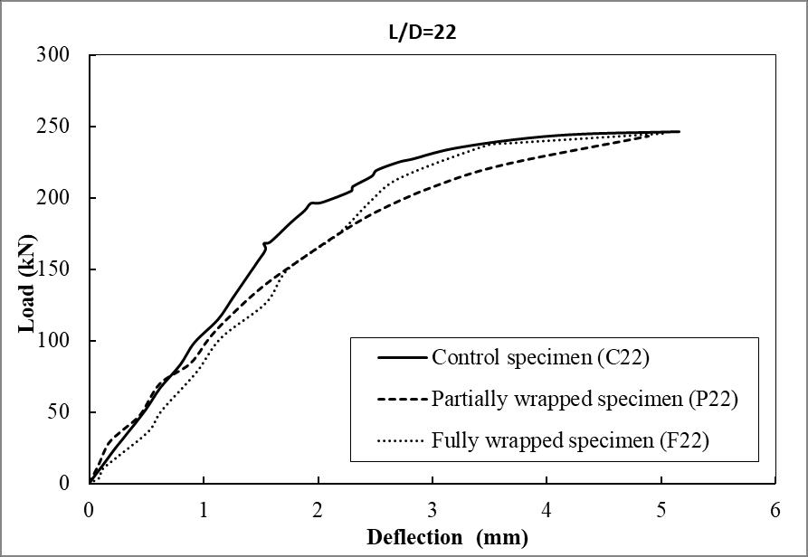
For control and strengthening specimens, the columns with lower slenderness ratio experienced lower deflection responses and with increasing the slenderness ratio the vertical deformation is increased which mean that the column stiffness is decreased by slenderness increasing. For the case of columns with slenderness ratio equal 22, the slope of the load – deflection curve for specimens C22, P22 and F22 appeared to be nearly horizontal near failure load with largest increases in vertical deformation which led to large lateral sway and then failed by buckling.
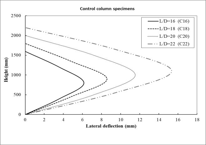
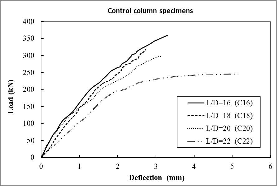
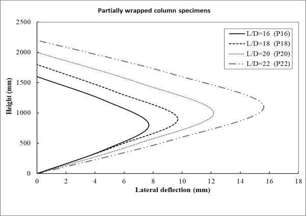
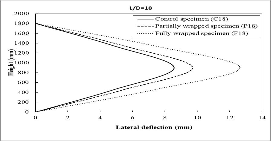
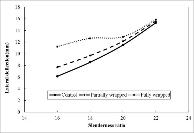
When the slenderness ratio is increased, the lateral deformation at mid height for control and strengthening is increased [2], [9] and [14]. In fully wrapped strengthened columns the effect of increasing the slenderness ratio from 16 to 22 in amplifying the lateral deformation is smallest with ranging from 111% to 140% compared to the un-strengthened columns and the partially wrapped strengthened columns. The increasing in lateral deformation for partially wrapped strengthening columns (ranging from 125% to 219% when increasing the slenderness ratio from 16 to 22) is less than for control columns (ranging from 140% to 260% when increasing the slenderness ratio from 16 to 22).
C18, C20 and C22.
International Journal of Civil and Structural Engineering Research ISSN 2348-7607 (Online) Vol. 10, Issue 2, pp: (10-33), Month: October 2022 - March 2023, Available at: www.researchpublish.com
Figure 6: Load – deflection responses relationship and buckling profile for column specimens P16, P18, P20 and P22.
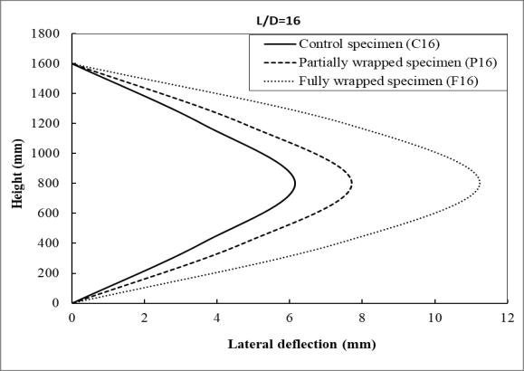
Figure 7: Load – deflection responses relationship and buckling profile for column specimens F16, F18, F20 and F22.
• Effect of wrapped schemes:
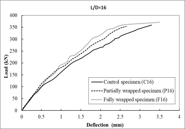
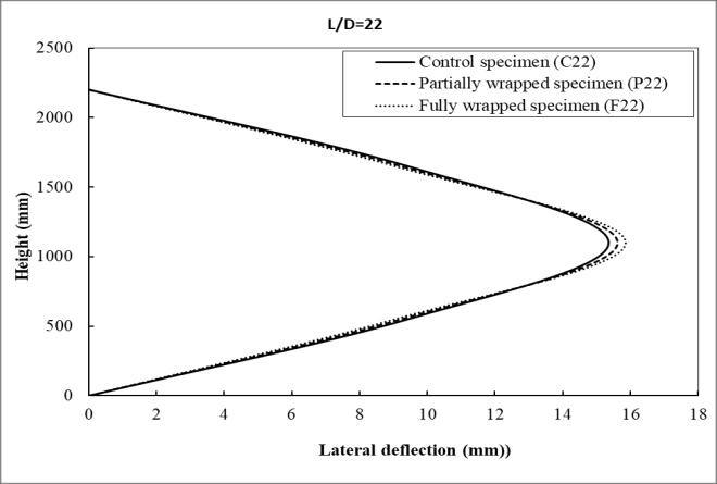
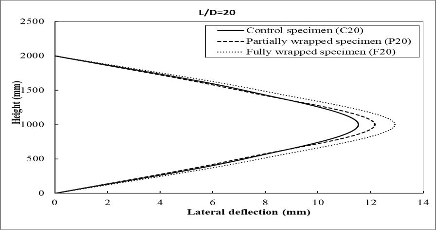
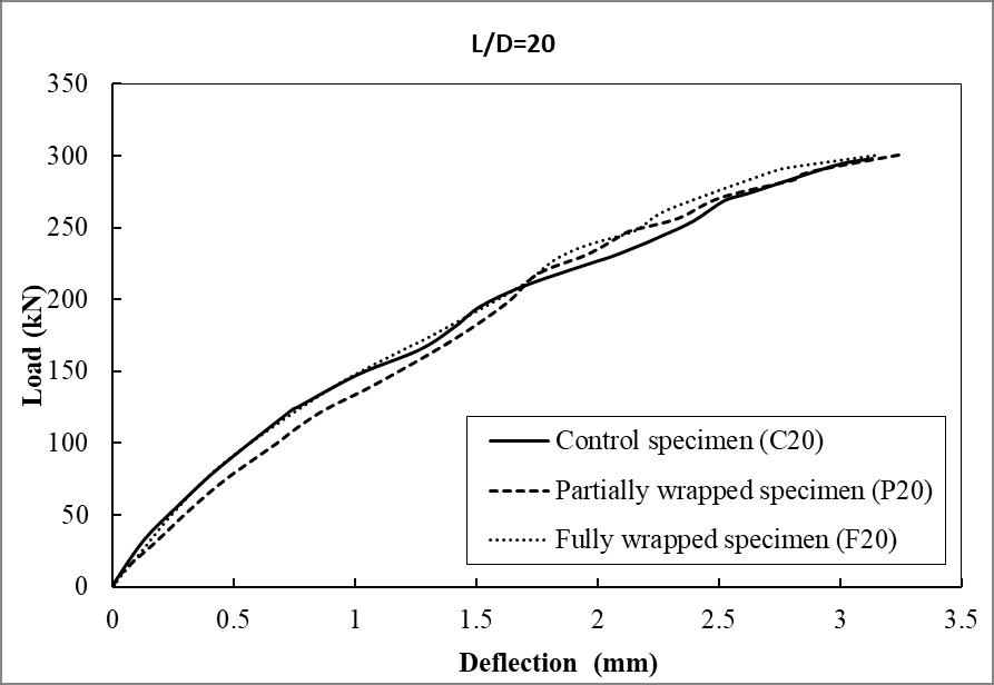
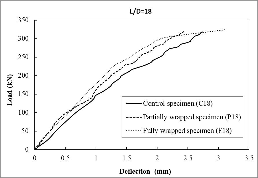
The second comparison is focused on the participating of the different strengthening schemes on enhancement the performance of slender columns having different slenderness ratio. Figures 8 to 11.
The resistance for columns with slenderness ratio equal 16, 18 and 20 is slightly increased for partially and fully strengthened with the same ratio. While for the case of slenderness ratio equal 22, the strengthening either partially or fully cannot improve the resistance of column but lead to reduction in capacity, i.e., the columns are not felt with strengthening and the load are reduced due to increasing the slenderness ratio as same as the case of there are unstrengthened.
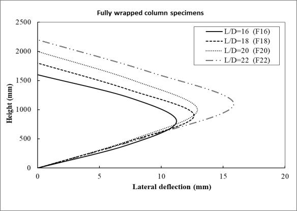
The lateral deformation is increased for columns fully strengthening more than for columns partially strengthening and these increases is reduced until diminished with increasing the slenderness ratio reaching to 22.
Figure 8: Load – deflection responses relationship and buckling profile for column specimens C16, P16 and F16.
International Journal of Civil and Structural Engineering Research ISSN 2348-7607 (Online) Vol. 10, Issue 2, pp: (10-33), Month: October 2022 - March 2023, Available at: www.researchpublish.com
Figure 9: Load – deflection responses relationship and buckling profile for column specimens C18, P18 and F18.
Figure 10: Load – deflection responses relationship and buckling profile for column specimens C20, P20 and F20.
Figure 11: Load – deflection responses relationship and buckling profile for column specimens C22, P22 and F22.
Figure 12 show comparisons between control un-strengthened, partially strengthened and fully strengthened column specimens at each slenderness ratio. It can be noted that the reduction in slender column capacity arising from the increasing in the slenderness ratio was greater for fully wrapped column than partially wrapped ones [10]. The capacity reduction for slender column due to the increasing in the slenderness ratio was the same for partially wrapped and unwrapped columns.
International Journal of Civil and Structural Engineering Research ISSN 2348-7607 (Online) Vol. 10, Issue 2, pp: (10-33), Month: October 2022 - March 2023, Available at: www.researchpublish.com
Figure 12: Slenderness ratio effect on ultimate load and lateral deformation for C, P and F column specimens.
C. Stiffness and Ductility
The stiffness is the slope of the load–deflection curve. These are two types of stiffness; pre–yielding stiffness [K1] and the post–yielding stiffness [K2], which can be calculated by Equations 1 and 2. Ductility is the change in the member shape without losing its capacity or failing. The ductility index ( is calculated by the ratio between the yielding deformation to the ultimate deformation as shown in Equation 3.
……………… [1] ……………… [2] ……………… [3]
Where: K1 = Pre–yield “Initial” Stiffness (kN/mm), Py = Yielding Load (kN), = Yielding Deflection (mm), K2 = Post–yield Stiffness “Effective” Stiffness (kN/mm), Pu = Ultimate Load (kN) and = Ultimate Deflection (mm).
Table VII: Comparison of initial stiffness, post yield stiffness, ductility index and toughness.
Group Specimens Py (kN) Pu (kN) (mm) (mm)
Control [C]
Partially wrapped [P]
Fully wrapped [F]
Pre-yielding stiffness Post-yielding stiffness Ductility index K1 (kN/mm)
Ratio W.R.T. (H/D)=16
Ratio W.R.T. [C]
K2 (kN/mm)
Ratio W.R.T. (H/D)=16
Ratio W.R.T. [C]
Ratio W.R.T. (H/D)=16
C16 80.2 359.8 0.403 3.3 199.01 96.51 8.19 C18 102 317.9 0.685 2.7 148.91 75% 107.15 111% 3.94 48% C20 126 298.2 0.89 3.13 141.57 71% 76.88 80% 3.52 43% C22 168 246.3 1.53 5.15 109.80 55% 21.63 22% 3.37 41%
Ratio W.R.T. [C]
P16 117 375.4 0.524 2.65 223.28 112% 121.54 126% 5.06 62%
P18 92.6 322.35 0.455 2.44 203.52 91% 137% 115.74 95% 108% 5.36 106% 136% P20 74.8 299.89 0.465 3.26 160.86 72% 114% 80.53 66% 105% 7.01 139% 199%
P22 70 244.92 0.618 4.89 113.27 51% 103% 40.95 34% 189% 7.91 156% 235%
F16 130.2 371.31 0.631 3.515 206.34 104% 83.60 87% 5.57 68%
F18 108 324.26 0.61 3.123 177.05 86% 119% 86.06 103% 80% 5.12 92% 130%
F20 109 300.2 0.646 3.148 168.73 82% 119% 76.42 91% 99% 4.87 87% 139%
F22 150 243.2 1.735 5.02 86.46 42% 79% 28.37 34% 131% 2.89 52% 86%
International Journal of Civil and Structural Engineering Research ISSN 2348-7607 (Online) Vol. 10, Issue 2, pp: (10-33), Month: October 2022 - March 2023, Available at: www.researchpublish.com
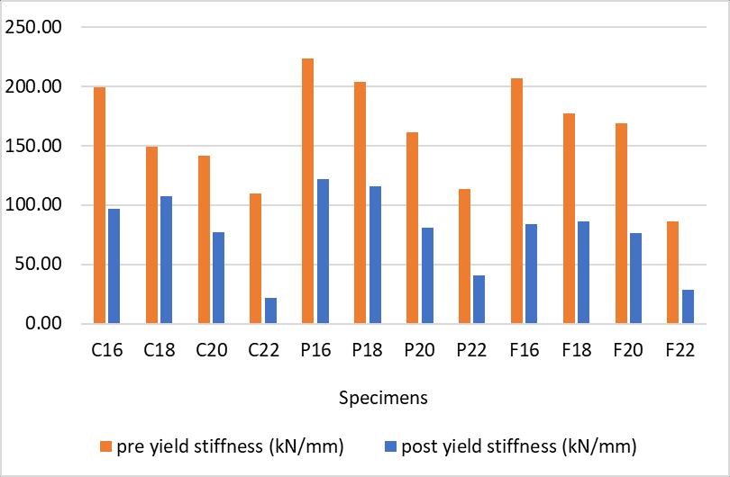
Figure 13: Initial and effective stiffness comparisons for tested columns.
Figure 14: Ductility index comparisons for tested columns.
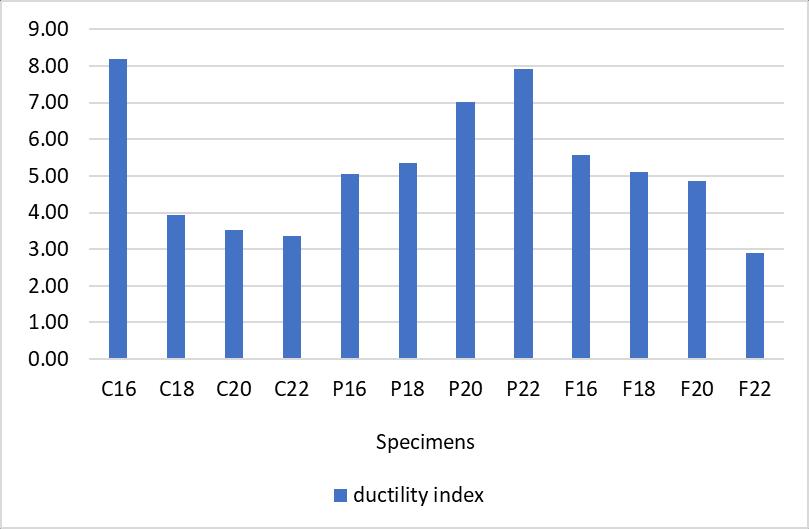
Table VII shows the flexural stiffness and ductility of column specimens. Figures 13 and 14 show the initial and effective stiffness and ductility index comparisons for tested columns. It is noted that the pre-yielding stiffness and post yielding stiffness are decreased with increasing the slenderness ratio. The pre-yielding stiffness for columns partially wrapped is slightly larger than columns with fully wrapped, while the post-yielding stiffness for partially wrapped columns is significantly larger than fully wrapped columns. It is obvious that columns with slenderness ratio equal 22 either unwrapped or wrapped have dramatic sudden drop in stiffness, hence it is proposed to limit the slenderness ratio (H/D) of columns up to 20. It is observed that the ductility of unwrapped and fully wrapped columns is reduced with increasing the slenderness ratio [1] and the opposite observation in partially wrapped columns.
V. DESIGN CODE PROVISIONS
This part compared the experimental and numerical calculations with the Code provisions by ACI (American Concrete Institute) and ECP (Egyptian Code) for un-strengthened and strengthened cases.
A. American Concrete Institute (ACI)
Building Code Requirements for Structural Concrete (ACI 318-19) [22] calculated the bearing capacity of columns by:
Po = [0.85*fc’ *(Ag-Ast)] + [fy *Ast]
International Journal of Civil and Structural Engineering Research ISSN 2348-7607 (Online) Vol. 10, Issue 2, pp: (10-33), Month: October 2022 - March 2023, Available at: www.researchpublish.com
The Design and Construction of Concrete structures with Externally FRP Systems for Strengthening (ACI 440.2R-17) [23] is calculated the bearing capacity of strengthened columns as:
Pmax =0.8*[[0.85 *fcc’ *(Ag-Ast)] + [fy Ast]] ……………… [5]
fcc’ = fcc’ + 3.3 ψf κa fl ……………… [6] fl = ……………… [7] εfe = κε εfu ……………… [8] fcc ’ = confined concrete compressive strength; fc ’ = unconfined concrete cylinder compressive strength, fy = specified yield strength of steel reinforcement; fl = maximum confinement pressure Ast = longitudinal reinforcement area; Ag = gross area of concrete section, ψf = FRP strength reduction factor equal to 0.95, εfu is the fiber elongation or strain; tf = thickness of one layer of FRP; n = number of FRP layers; D = circular column diameter; Ef = FRP modulus of elasticity; εfe = effective strain in FRP reinforcement; κa = factor of confinement efficiency for circular column= 1.0 and κε = factor of efficiency for GFRP strain= 0.565.
WHERE:
B. EGYPT Code (ECP)
The Egyptian Code for Design and Construction of Concrete members (ECP 203-2020) [21] was calculated the column bearing capacity as: Po = [0.525 *fc’ *(Ag-Ast)] + [0.77 *fy *Ast ] ……………… [9]
The Egyptian Code for strengthening by fiber reinforced polymer (ECP 208-2015) [24] was used to calculate the loads of strengthened circular columns as the following:
……………… [10]
Po = 0.525 fcuc (Ag-Ast) + 0.77 fy Ast
WHERE: fcuc = – 1.25] ……………… [11] ……………… [12] ……………… [13]
For fully wrapped: ……………… [14] ……………… [15]
For partially wrapped: ……………… [16] ……………… [17] ……………… [18]
n = the number of fiber layers, tf = the thickness of the fiber layer, D is the column diameter, εfu = the fiber strain, CE = a reduction value taken as 0.75, ε*fu = ultimate strain of the fiber, ɣf = the ultimate strength reduction factor for fibers taken as 1.3, fcu = the concrete compressive strength, f1 = the side stress of the column sides, efficiency factor of partially wrapped in circular columns and S = spacing between successive fiber strips.
International Journal of Civil and Structural Engineering Research ISSN 2348-7607 (Online) Vol. 10, Issue 2, pp: (10-33), Month: October 2022 - March 2023, Available at: www.researchpublish.com
Table VIII: The load capacity for un-strengthened columns obtained from code provisions using ACI 318-19 and ECP 213–2020 compared with the experimental test results
EXP ACI318 EQU (ACI318 EQU / EXP % ECP203 EQU (ECP203 EQU / EXP) % Variation between ECP to ACI
C16 359.8 273.8 76% 200.7 56% -20%
C18 317.9 273.8 86% 200.7 63% -23%
C20 298.2 273.8 92% 200.7 67% -25%
C22 246.3 273.8 111% 200.7 81% -30%
Table IX: The load capacity for strengthened columns obtained from code provisions using ACI440.2R-17 and ECP 208-2015 compared with the experimental test results
EXP ACI440.2R EQU (ACI440.2R EQU / EXP) % ECP208 EQU (ECP208 EQU / EXP) % Variation between ECP to ACI
F16 371.31 277.8 75% 225.2 61% -14%
F18 324.26 277.8 86% 225.2 69% -16%
F20 300.2 277.8 93% 225.2 75% -18%
F22 244.92 277.8 113% 225.2 92% -21%
P16 354.1 277.8 78% 200.7 57% -22%
P18 320.2 277.8 87% 200.7 63% -24%
P20 301 277.8 92% 200.7 67% -26%
P22 243.2 277.8 114% 200.7 83% -32%
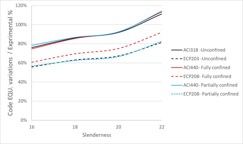
Figure 15: relation between the (experimental/ code equation) % and slenderness ratios
Table VIII, IX and Figure 15 showed the difference in axial load capacity between ECP 203–2020 and ACI 318-19 code provisions for un-strengthened columns and between ECP 208–2015 and ACI 440.2R-17 for strengthened columns with the results from experimental test. It is obvious that for all studied codes provisions; as the slenderness ratio increased the difference between the code equation and experimental results is decreased. This is due to the reduced values of resistance of as slenderness ratio increased while the codes equations did not consider the effect of slenderness ratio in the calculated column load capacity i.e., these values are constant although of the slenderness ratio is changed.
It can be observed that ACI318 and ACI440.2R are less predicted the load capacity of slender columns up to slenderness ratio equal 20. In case of the slenderness ratio is more than 20 ACI318 and ACI440.2R are get higher axial load capacity when compared with experimental works. ECP203 and ECP208 are less predicted the load capacity of slender columns for all slenderness ratios.
In addition, ECP203 and ECP208 are less predicted the slender columns capacity than ACI318 and ACI440.2R. ECP203 is more conservative than ACI318 for unconfined columns with difference ranged about 20-30%. In addition, ECP208 is more conservative than ACI440.2R for columns strengthened partially and fully wrapped strengthened with difference ranged about 14-21% and 22-32%, respectively.
International Journal of Civil and Structural Engineering Research ISSN 2348-7607 (Online) Vol. 10, Issue 2, pp: (10-33), Month: October 2022 - March 2023, Available at: www.researchpublish.com
VI. ANALYTICAL MODELLING
The analytical works were conducted using ANSYS 19 [25] as the finite element software. These analytical studies were carried out to check the reality in capturing the experimental results. Then, more extended analytical works were constructed for widely extending explore the effects of different parameters.
For modeling, the following elements are used. The SOLID 65 element is used to model concrete material. This element has capable to present the plastic deformation, cracking and crushing. The LINK180 is used to model dicrete steel reinforcement bars that is a uniaxial compression-tension element. The steel loading plates was modeled by SOLID185 element large deflection and large strain capabilities. SHELL181 is used to model FRP laminates, and this is suitable for analyzing layered thin or thick shells.
For concrete material, both linear and multi-linear isotropic material properties are needed. The linear isotropic properties are defined by the modulus of elasticity that is equal Ec = 4400 , and the passion’s ratio. The multi-linear properties are defined using stress-strain curve for concrete. The bilinear isotropic properties are used to define reinforcing steel bars. The linear isotropic properties; EX and PRXY; are used to model loading steel plates. The material properties for GFRP are taken as linear orthotropic. The Material Models for SOLID65, LINK180, SOLID185 and SHELL181 are shown from Table X to Table XIII
Table X: Concrete Material Model used for Solid 65
Linear isotropic EX 28515.26 PRXY 0.2 Concrete
Shear transfer for open crack 0.3 Shear transfer for closed crack 0.8 Cracking stress 4.2 Crushing stress 42 Multi-linear isotropic strain stress 0 0 0.000441869 12.6 0.0005 13.85837674 0.001 25.56876413 0.0015 33.96599274 0.002 39.03653505 0.002945791 42 0.003 42
Table XI: Material Models link 180 for steel reinforcement
Linear isotropic EX 200000 PRXY 0.3 Bilinear isotropic yielding stress 240 Tangent modulus of elasticity 0
Table XII: Steel Plates Material Models using Solid 185
Linear isotropic EX 200000 PRXY 0.3
International Journal of Civil and Structural Engineering Research ISSN 2348-7607 (Online) Vol. 10, Issue 2, pp: (10-33), Month: October 2022 - March 2023, Available at: www.researchpublish.com
Table XIII: Glass Fiber Wrap Material Models using Shell181
Multi-linear elastic Strain Stress 0.0214 1500
Linear orthotropic

Modulus of elasticity
EX 70093 EY 0 EZ 0
modulus
The columns and the loading plates were modeled by Volumes. The GFRP laminates were modeled as shells on the column surface area. All column models had a same cross-section area of radius (R=50mm) and different heights of 1600 mm, 1800 mm, 2000 mm and 2200 mm. Figure 16 shows the Volumes that created by ANSYS. The volume SWEEP command was used to divide the concrete, steel plates. The convergence of results is achieved by increasing in the mesh density up to reach to have a negligible effect on the results. So, the used elements mesh size is not exceeded 20 where is not consuming the analysis time and giving acceptable results. Meshing of reinforcement is divided with certain size to match and merge with volumes mesh nodes. The area QUAD command was used to mesh the shell elements representing the GFRP laminate. The bond between FRP and concrete and between concrete and steel reinforcement are assumed to be full bond.


A pressure load was applied on the upper loading plate and hinge supports were defined at the outer surface area of the two loading plates. The top plate was prevented to transmit in both X and Z directions to allow the vertical deformation in Y direction of the model, while the bottom plate was constrained in X, Y, and Z directions. Figure 17 shows the applied load and supports on the meshed column model.
The nonlinear large displacement static analysis is carried out using Full Newton-Raphson method which having a sufficiently number of sub-steps to capture the cracking, yielding, and failure stages. A convergence tolerance with 0.05 based on the displacement degree of freedom is assumed. The automatic time stepping is set as a program chosen to help in reducing the computational time by regulating the sub-step size according to the convergence of the solution. Typical commands for nonlinear static analysis are shown in Table XIV
International Journal of Civil and Structural Engineering Research ISSN 2348-7607 (Online) Vol. 10, Issue 2, pp: (10-33), Month: October 2022 - March 2023, Available at: www.researchpublish.com
Table XIV: Nonlinear Analysis Commands
Analysis option Large displacement static Prestress effects No Time at end of load-step 500000 Automatic time-stepping Prog chosen Time step-size 1000 Min time-step 100 Max time-step 10000 Frequency Write every substep Write items to result file All solution items
A. Verification of model with experimental works
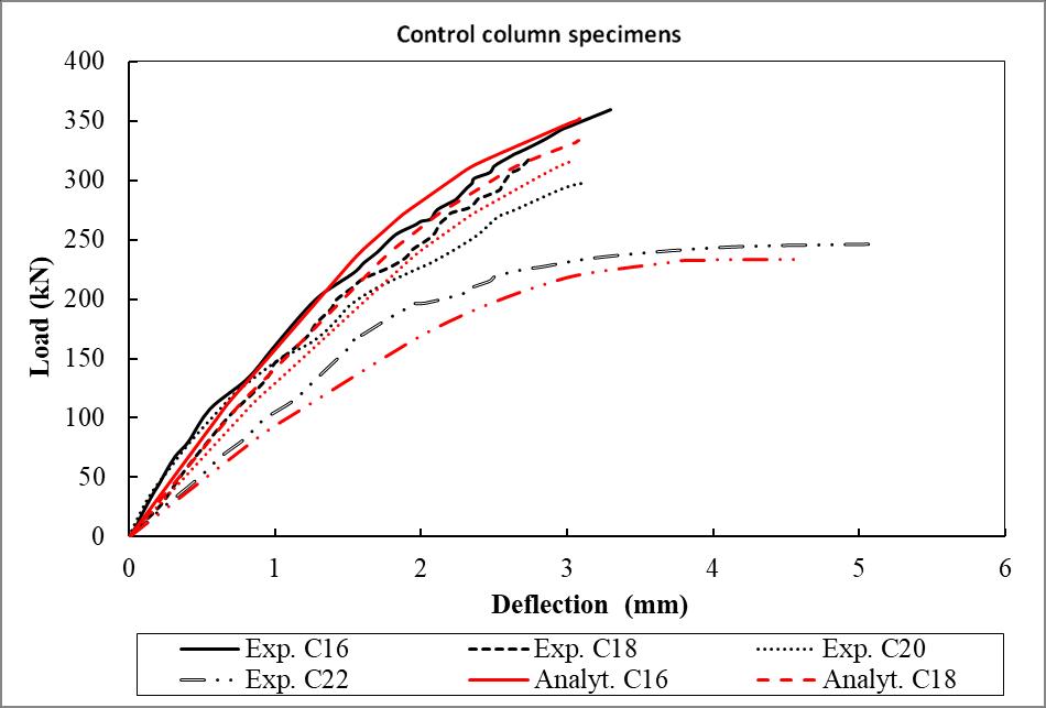
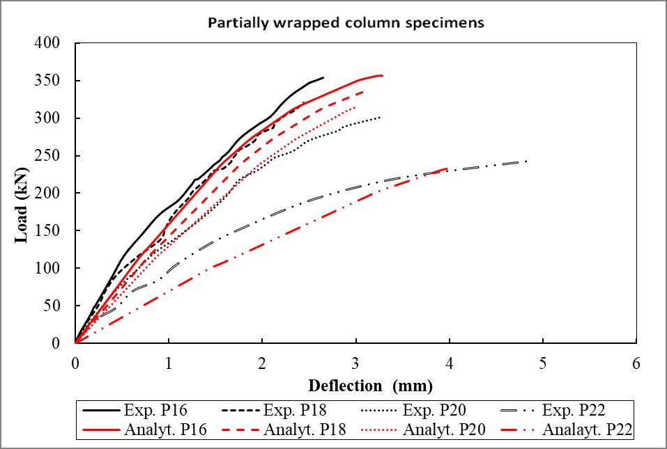
In this part, a comparison between the experimental and analytical results will be illustrated. This comparison included the failure mode, ultimate strength, and deflections for the experimentally tested and the analytically modeled column specimens. Table XV listed the convergence of the experimental results with analytical ones. Figures 18 to 20 presents the convergence between the analytical and experimental load – deflection curves. Figures 21 to 23 shows the comparison between analytical and experimental failure modes. All modeled column specimens appeared to have the same failure behavior as their corresponding experimental ones. It was obvious that the analytical results were very close to the experimental ones. For the ultimate load and the vertical displacement, the variation between the experimental and analytical results are ranged between (0-6) % and (0-21) %, respectively, which indicated the validity of the analytical model and the possibility of using it in further parametric studies.
Table XV: Comparison between experimental and analytical results.
Group name Column ID
Control (C)
Fully wrapped (F)
Partially wrapped (P)
Experimental results Analytical results (Pf / Panalyt.) (δf. / δanalyt.) Failure load (Pf) Failure disp. (δf)
Failure load (Panalyt.)
Failure disp. (δanalyt.) (kN) (mm) (kN) (mm)
C16 359.8 3.296 352.13 3.087 1.02 1.07 C18 317.9 2.738 333.29 3.08 0.95 0.89 C20 298.2 3.13 316.69 3.045 0.94 1.03 C22 246.3 5.154 233.71 4.612 1.05 1.12
F16 371.31 3.515 364.48 3.045 1.02 1.15
F18 324.26 3.123 341.34 3.046 0.95 1.03 F20 300.2 3.148 319.8 3.208 0.94 0.98 F22 244.92 5.021 233.97 4.375 1.05 1.15
P16 354.1 2.651 356.67 3.285 0.99 0.81
P18 320.2 2.441 336.2 3.098 0.95 0.79 P20 301 3.26 315.89 3.019 0.95 1.08 P22 243.2 4.59 233.89 4.041 1.03 1.14
Figure 18: Load-deflection curves of control column specimens for the experimental and analytical model results.
International Journal of Civil and Structural Engineering Research ISSN 2348-7607 (Online) Vol. 10, Issue 2, pp: (10-33), Month: October 2022 - March 2023, Available at: www.researchpublish.com
Figure 19: Load-deflection curves of partially wrapped column specimens for the experimental and analytical model results.
Figure 20: Load-deflection curves of fully wrapped column specimens for the experimental and analytical model results.
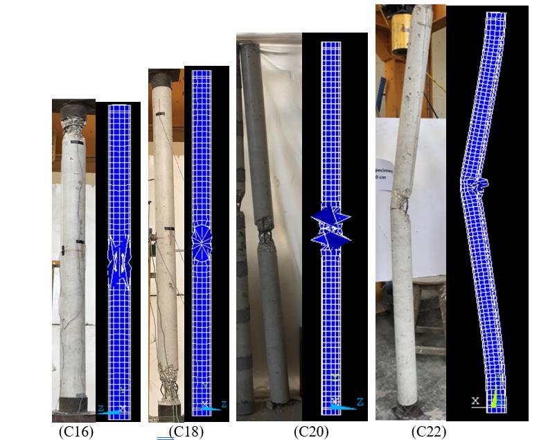
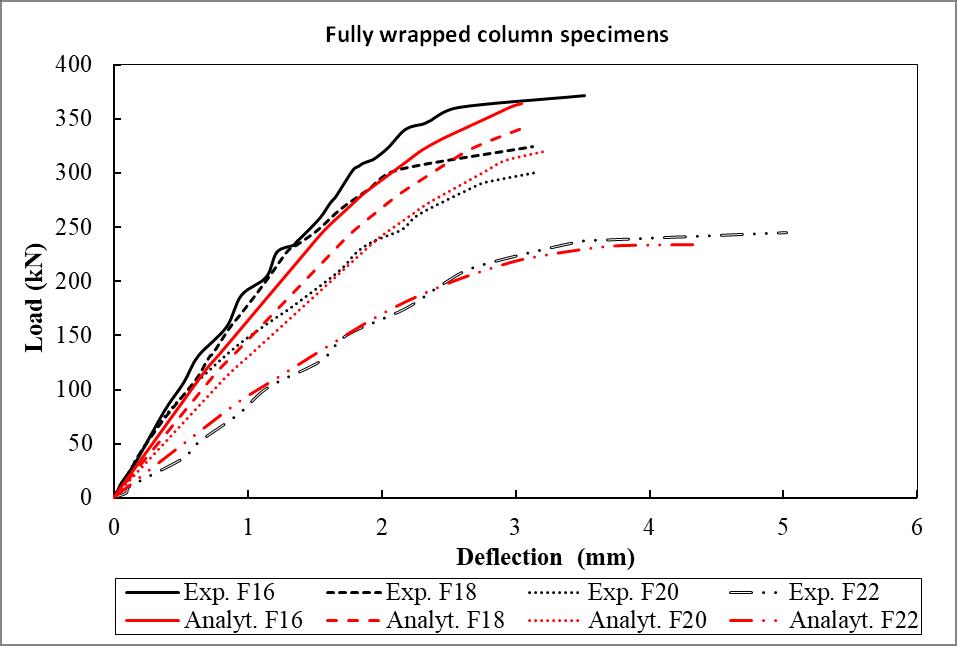
Figure 21: Failure behavior comparisons between experimental and analytical control column specimens.
International Journal of Civil and Structural
Research ISSN 2348-7607 (Online) Vol. 10, Issue 2, pp: (10-33), Month: October 2022 - March 2023, Available at: www.researchpublish.com
B. Parametric study
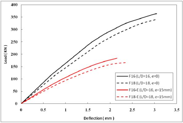
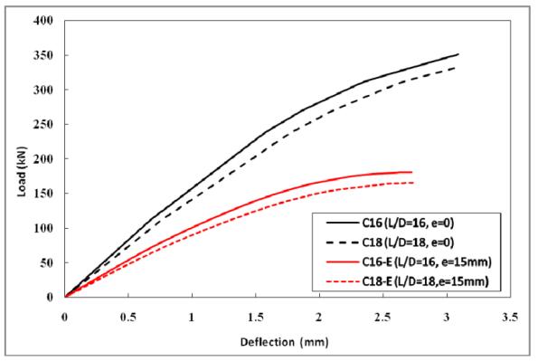
In this part, the effect of using laminates in the longitudinal direction with the transverse laminates and the effect of initial load eccentricity on wrapped and unwrapped slender columns are discussed. The study consists of four groups; Group (F1-1) included four columns F16-1-1, F18-1-1, F20-1-1 and F22-1-1 having the same dimensions, reinforcements, concrete strength and slenderness ratios 16, 18, 20 and 22 as the previously tested columns but fully wrapped in both transverse and longitudinal directions; one layer of GFRP laminate in each direction, Group (C-E) included two columns C16-E and C18-E; these columns are identical to the previously tested control column specimens C16 and C18 but subjected to initial load eccentricity of 15 mm, Group (F-E) included two columns F16-E and F18-E; these columns are identical to the previously tested fully wrapped column specimens in hoop direction F16 and F18 but subjected to initial load eccentricity of 15 mm and Group (F-E-1-1) included two columns F16-E-1-1 and F18-E-1-1; these columns are identical to the previously tested fully wrapped column specimens in both hoop and longitudinal directions F16-1-1 and F18-1-1 but subjected to initial load eccentricity of 15 mm. Table XVI showed the results of grouping of analytically tested columns and the studied parameter.

International Journal of Civil and Structural Engineering Research ISSN 2348-7607 (Online) Vol. 10, Issue 2, pp: (10-33), Month: October 2022 - March 2023, Available at: www.researchpublish.com
Table XVI: Results and grouping of columns based on parametric study.
Group Specimen ID Slendern ess ratio
C16 16
C
F
F-1-1
Strengthening details
Initial load eccentricity (e) (mm)
Ultimate load (Pu) (kN)
352.13
C18 18 333.29
No strengthening
C20 20 316.69
C22 22 233.71
F16 16
364.48
F18 18 341.34 F20 20 319.8
Fully wrapped with 1 HZ layer
None
F22 22 233.97
F16-1-1 16
381.78
F18-1-1 18 355.89 F20-1-1 20 325.89 F22-1-1 22 235.89
Fully wrapped with 1 HZ layer + 1 VL layer
C-E C16-E 16 No strengthening
180.8 C18-E 18 165.45
F-E F16-E 16 Fully wrapped with 1 HZ layer 184.48 F18-E 18 167.08
15 mm
F-E-1-1 F16-E-1-1 16 Fully wrapped with 1 HZ layer + 1 VL layer 188.03 F18-E-1-1 18 170.89
• Effect of strengthening orientation:
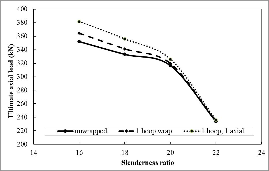
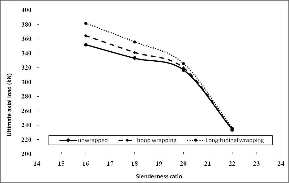
In columns strengthened with both transverse and longitudinal GFRP sheets, the longitudinal wraps contribute significantly to the strength of the slender columns, when secondary moments are large and the flexural stiffness of concrete is reduced hence, the longitudinal GFRP wraps can improve the resistance of slender columns. The improvement of adding longitudinal wrap is reduced with increasing the slenderness ratio. One layer of longitudinal wrap succeeds in increasing the resistance for columns F16-1-1, F18-1-1, F20-1-1 and F22-1-1 by 4.75%, 4.2%, 1.9% and 0.8% respectively compared to the columns with transverse wraps only. Figure 24 showed the effect of GFRP wraps orientation on strengthening slender columns.
Figure 24: Effect of orientation of GFRP wraps on strengthening slender columns.
• Effect of load eccentricity:
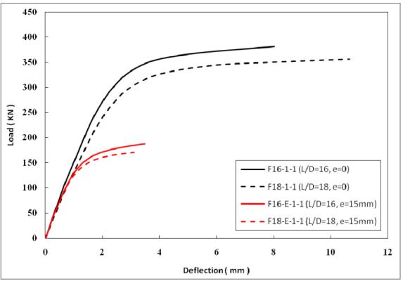
Figure 25 shows comparison between load-deflection responses for slender columns subjected to concentric and eccentric loading: (a) unwrapped; (b) 1 hoop wrap; (c) 1 hoop+1 longitudinal wrapping. Figure 26 presents the effect of load eccentricity on strengthening the slender columns. Slender columns subjected to initial load eccentricities suffered from a
International Journal of Civil and Structural Engineering Research ISSN 2348-7607 (Online) Vol. 10, Issue 2, pp: (10-33), Month: October 2022 - March 2023, Available at: www.researchpublish.com
severe reduction in their strength as they are exposed to high bending moment resulted from large lateral deformations that decrease their axial resistance [19]. Unconfined slender columns with slenderness ratios 16 and 18 and exposed to initial load eccentricity (e/D=0.15) suffered a reduction in their resistance by 48.6 % and 50.3%, respectively compared to the unconfined slender columns loaded concentrically. GFRP confining for slender columns with initial load eccentricity was found to have insignificant contribution in increasing their strength. The resistance for GFRP hoop wrapped columns F16-E and F18-E were barely increased by 2% and 0.98%, respectively, while the resistance for GFRP longitudinal wrapped columns F16-E-1-1 and F18-E-1-1 were increased by 4% and 3.29%, respectively compared to their corresponding unconfined ones C16-E and C18-E. (a) (b) (c)
Figure 25: Comparison between load-deflection responses for slender columns subjected to concentric and eccentric loading: (a) unwrapped; (b) hoop wraps; (c) hoops + longitudinal wraps
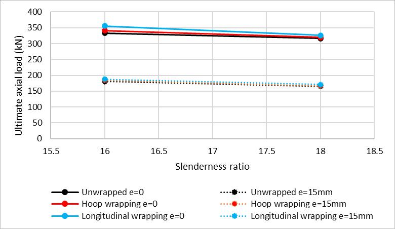
Figure 26: Effect of load eccentricity on strengthening the slender columns
Publish Journals
International Journal of Civil and Structural Engineering Research ISSN 2348-7607 (Online) Vol. 10, Issue 2, pp: (10-33), Month: October 2022 - March 2023, Available at: www.researchpublish.com
VII. CONCLUSION
This work studied the performance of columns with highly slenderness and evaluated the efficiency of the strengthening these columns with GFRP hoop wraps either partially or fully. Twelve column specimens with the slenderness ratios (H/D) 16, 18, 20, and 22 are tested under axial concentric load up to failure. Then, the experimental are compared with the ECP and ACI codes provisions to test the reliability of the codes equations to predict the failure load of unconfined and confined columns. In addition, the numerical models using ANSYS are conducted to check their validation with the experimental results and then use for more extensive parametric studies such as the effect of load eccentricity and the effect of other different strengthening schemes. The results reached are limited to the specified cases studied and more studies are needed. The following can be concluded:
1) For Fully GFRP confining, the failure behavior of slender RC columns with slenderness ratios less than 20 change from crushing failure to buckling failure. For columns with slenderness ratios more than 20, the failure remains due to buckling same as un-confined ones but with less lateral deformations.
2) Partially GFRP confining is weaken the column with slenderness ratios less than 20 at regions that do not cover by strips and the failure will be caused due to crushing at the same locations as un-confined ones. For columns with slenderness ratios more than 20, the failure remains due to buckling same as un-confined ones with less lateral deformations.
3) For un-strengthened or strengthened slender columns, increasing the slenderness ratio of columns causes a reduction in the ultimate axial load, axial deformation arising from decreasing the column stiffness but increasing the lateral deformation in the mid-height.
4) The fully wrapped of slender columns reduced the amplification of lateral deformation at mid height of columns (ranging from 111% to 140%) less than partially wrapped columns (ranging from 125% to 219%) and less than unwrapped columns (ranging from 140% to 260%) when increasing the slenderness ratio (H/D) from 16 to 22.
5) The partially wrapped and fully wrapped for columns with slenderness ratio less than 22 is slightly increased resistance with the same ratio. While for the case of slenderness ratio equal to 22, the columns cannot feel with strengthening either partially or fully.
6) As the slenderness ratio increased the difference between the ACI and ECP code equations and experimental results is decreased. This is due to the code’s equation does not consider the effect of slenderness in calculating the column capacity, while experimentally, the column capacity is sensitive to its slenderness.
7) ACI318 and ACI440.2R are less predicted the load capacity of slender columns with slenderness ratio up to 20. While ECP203 and ECP208 are less predicted the load capacity of slender columns for different slenderness ratios.
8) ECP203 is more conservative than ACI318 for unconfined columns with difference ranged about 20-30%. In addition, ECP208 is more conservative than ACI440.2R for columns strengthened partially and fully wrapped strengthened with difference ranged about 14-21% and 22-32%, respectively.
9) An analytical model can be presented in a good manner to predict the failure load and deformations and can capture the failure modes either crashing or buckling in unconfined and GFRP confined slender columns.
10) Applying longitudinal wraps beside the hoop wraps succeeded to improve the resistance for confined slender RC columns.
11) The improvement of adding longitudinal wrap is reduced with increasing the slenderness ratio. The load capacities of confined slender columns with both longitudinal and hoop wraps increased by 4.75%, 4.2%, 1.9% and 0.8% for columns with H/D = 16, 18, 20 and 22 respectively compared to the columns with transverse wraps only.
12) Slender columns subjected to initial load eccentricity suffer from a severe reduction in their strength. Applying initial load eccentricity of (e/D = 0.15) caused a reduction in the load capacities for columns with H/D = 16 and 18 by 48.6% and 50.3% respectively compared to their corresponding ones loaded concentrically.
13) For columns loaded eccentrically, the load capacities of confined slender columns with hoop wraps were barely increased by 2% and 0.98%, while for confined slender columns with both longitudinal and hoop wraps increased by 4% and 3.29% for columns with H/D = 16 and 18 respectively compared to their corresponding unconfined ones.
International Journal of Civil and Structural Engineering Research ISSN 2348-7607 (Online) Vol. 10, Issue 2, pp: (10-33), Month: October 2022 - March 2023, Available at: www.researchpublish.com
14) It is suggested to limit the value of slenderness ratio to be not more than 20 for unconfined or confined (either wrapped either hoops or longitudinal) circular RC slender columns under concentric or eccentric axial loading.
15) It should be noted that the conclusion of this study is valid in the range of the tested specimens of the experimental studies. Further studies using different materials, dimensions, loading conditions are required.
Competing Interest Declaration
The authors declare no conflict interests.
ACKNOWLEDGMENT
The authors greatly thankful the technical staff of the reinforced concrete laboratory at Helwan University.
REFERENCES
[1] Pan, J. L., Xu, T., & Hu, Z. J. (2007). Experimental investigation of resistance of the slender reinforced concrete columns wrapped with FRP. Construction and Building Materials, Volume 21, Issue 11, November 2007, Pages 19911996.
[2] Fitzwilliam, J., & Bisby, L. A. (2010). Slenderness effects on circular CFRP confined reinforced concrete col-umns. Journal of Composites for Construction, 14(3), 280-288.
[3] Soliman, A. E. K. S. (2011). Behavior of long confined concrete column. Ain Shams Engineering Journal, 2(3-4), 141-148.
[4] Chikh, N., Benzaid, R., & Mesbah, H. (2012). An experimental investigation of circular RC columns with various slenderness confined with CFRP sheets. Arabian Journal for Science and Engineering, 37(2), 315-323.
[5] Raval, R., & Dave, U. (2013). Behavior of GFRP wrapped RC Columns of different shapes. Procedia Engineering, 51, 240-249.
[6] Saravanan, J., Suguna, K., & Raghunath, P. N. (2014). Slenderness effect on high strength concrete columns confined with GFRP wraps. Indian Journal of Engineering and Materials Sciences 21(1):67-74.
[7] Dundar, C., Erturkmen, D., & Tokgoz, S. (2015). Studies on carbon fiber polymer confined slender plain and steel fi-ber reinforced concrete columns. Engineering structures, 102, 31-39.
[8] Nadaf, F., & Biradar, P. (2015). Behavior of Slender Column Subjected to Eccentric Loading. International Journal of Innovations in Engineering Research and Technology, 2(4).
[9] Maranan, G. B., Manalo, A. C., Benmokrane, B., Karunasena, W., & Mendis, P. (2016). Behavior of concentrically loaded geopolymer-concrete circular columns reinforced longitudinally and transversely with GFRP bars. Engineering Structures, 117, 422-436.
[10] Ramana Gopal, S. (2017). An experimental study on FRC infilled steel tubular columns under eccentric load-ing. KSCE Journal of Civil Engineering, 21(3), 923-927.
[11] Farooq, H., Usman, M., Mehmood, K., Malik, M. S., & Hanif, A. (2018, September). Effect of steel confinement on ax-ially loaded short concrete columns. In IOP Conference Series: Materials Science and Engineering (Vol. 414, No. 1, p. 012026). IOP Publishing.
[12] Lu, Y., Zhu, T., Li, S., Li, W., & Li, N. (2018). Axial behaviour of slender RC circular columns strengthened with cir-cular CFST jackets. Advances in Civil Engineering Volume 2018, Article ID 7923575, 11 pages https://doi.org/ 10.1155/2018/7923575
[13] Montaser, W., El-Kateb, M., & Nabil, M. (2019) Experimental and Analytical Study of Square Columns Strengthened and Repaired Using CFRP Sheets Partially and Fully Wrapped. The International Journal of Engineering and Science (IJES), Volume [8], Issue [4], Series II, PP 45-57, ISSN (e): 2319 – 1813 ISSN (p): 23-19 – 1805
[14] Xing, L., Lin, G., & Chen, J. F. (2020). Behavior of FRP-confined circular RC columns under eccentric compression. Journal of Composites for Construction, Volume 24 Issue 4 - August 2020
International Journal of Civil and Structural Engineering Research ISSN 2348-7607 (Online) Vol. 10, Issue 2, pp: (10-33), Month: October 2022 - March 2023, Available at: www.researchpublish.com
[15] Hu, Z., Li, Q., Yan, H., & Wen, Y. (2021). Experimental Study on Slender CFRP-Confined Circular RC Columns under Axial Compression. Applied Sciences, 11(9), 3968.
[16] Cassese, P.; Menna, C.; Occhiuzzi, A.; Asprone, D. Experimental Behavior of Existing RC Columns Strengthened with HPFRC Jacket under Concentric and Eccentric Compressive Load. Buildings 2021, 11, 521. https://doi.org/ 10.3390/ buildings11110521
[17] Miao, K.; Wei, Y.; Zhang, X.; Zheng, K.; Dong, F. Performance of Circular Concrete-Filled FRP-Grooved Steel Com-posite Tube Columns under Axial Compression. Polymers 2021, 13, 3638. https://doi.org/10.3390/ polym132 13638.
[18] Koosha Khorramian and Pedram Sadeghian. Hybrid system of longitudinal CFRP laminates and GFRP wraps for strengthening of existing circular concrete columns. Engineering Structures 235 (2021) 112028
[19] Tin, H.-X.; Thuy, N.-T.; Seo, S.-Y. Structural Behavior of RC Column Confined by FRP Sheet under Uniaxial and Bi-axial Load. Polymers 2022, 14, 75. https:// doi.org/10.3390/polym14010075
[20] Djarir Yahiaoui, Mohamed Saadi and Tayeb Bouzid. Compressive Behavior of Concrete Containing Glass Fibers and Confined with Glass FRP Composites. International Journal of Concrete Structures and Materials (2022) 16:37
[21] ECP 203-2020 “Egyptian Code of Practice for Design and Construction of Concrete Structures Code”, Standing Committee to prepare the Egyptian, “HBRC, Cairo, Egypt, 2020.
[22] ACI (American Concrete Institute). Building Code Requirements for Structural Concrete; ACI 318-19; ACI: Farming-ton Hills, MI, USA, 2019.
[23] ACI (American Concrete Institute). Guide for the Design and Construction of Externally Bonded FRP Systems for Strengthening Concrete Structures; ACI 440.2R-17; ACI: Farmington Hills, MI, USA, 2017.
[24] ECP 208-2015 “Egyptian Code Egyptian Code for the use of fiber reinforced polymer (FRP) in the construction fields”, Standing Committee to prepare the Egyptian, “HBRC, Cairo-Egypt, 2005.
[25] ANSYS (2018). ANSYS User’s Manual Revision 19.0, ANSYS, Inc., USA.
