International Journal of Civil and Structural Engineering Research ISSN 2348-7607 (Online) Vol. 7, Issue 1, pp: (134-145), Month: April 2019 - September 2019, Available at: www.researchpublish.com
Prevention and Repair of End-Region Cracks in Prestressed Concrete Girders:AState-of-theArt Review
Yoon-Si Lee1
1
2
, Mahmoodreza Soltani2
, Karlee Schweigert3
3
, and Sadit MaharjanAssociate Professor, Civil Engineering and Construction, Bradley University, Peoria, IL, USA
Assistant Professor, Civil Engineering and Construction, Bradley University, Peoria, IL, USA
3Graduate Students, Civil Engineering and Construction, Bradley University, Peoria, IL, USA
Abstract: In recent decades, prestressed concrete girders have primarily been used in bridges worldwide. One of the common issues frequently observed in these prestressed concrete girders is the end-region cracking due to the application of prestressing forces. Numerous repair and prevention techniques have been proposed and investigated in this field, including the application of mortar, fiber-reinforced polymers wrapping, epoxy injection, post-tensioning, and strand debonding. This study seeks to elucidate a methodical review on the current body of knowledge (comprised of studies from 1982 to 2019) discussing the methods to repair and retrofit, and prevent the formation and propagation of end-region cracks in prestressed concrete girders.
Keywords: Prestressed Concrete; End-Region Crack; Fiber Reinforced Polymers; Epoxy Injection; Post-tensioning; Strand debonding.
1. INTRODUCTION
1.1. Problem Statement
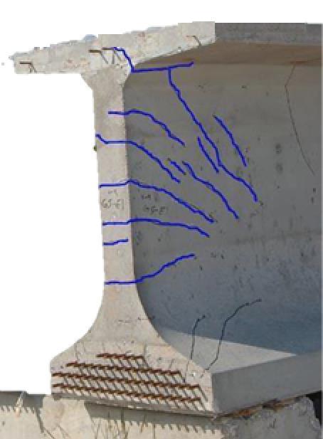
According to the 2017 Report Card [1] published by the American Society of Civil Engineers, the overall national grades for the U.S. infrastructure and for ―Bridges‖ category are at a ―D+‖ and a ―C+‖, respectively. Approximately forty percent of the U.S. bridges are fifty years or older and nine percent of the bridges are reported ―structurally deficient‖ or are in need of repair or replacement due to their ―functional obsolescence‖ status. It was recently estimated that $123-billion (US dollars) is needed to rehabilitate the country’s bridge backlog. Furthermore, the Federal Highway Administration (FHWA) estimates that more than thirty percent of existing bridges have already exceeded their service life (fifty years mostly) and will require more budgets for the maintenance and rehabilitation of these bridges in the near future [2]. As these bridges continue to deteriorate, the problems become further compounded by increases in legal load limits, increasing traffic volumes, limited budgets, and substantial costs associated with proper maintenance, rehabilitation or replacement of these deficient bridges. One of the key types of damage contributing to the need of bridge repair is the end-region cracking in girders, where very little confinement exists. In recent years, these cracks have become prevalent with the use of relatively high strength concrete, deep girders, and high prestressing force that are quickly developed near the end-region of girders (Fig. 1).
Bridge engineers and owners have spent considerable time and effort researching viable, cost effective solutions to improve the condition, durability, and capacity of bridges and, thus, reduce overall life-cycle costs. There have been numerous girder end repair techniques proposed by researchers such as the application of mortar, an epoxy injection, the use of FRP strips, FRP fabrics, near-surface mounted FRP, prestressed FRP, post-tensioned FRP, and strand slicing and external post-tensioning. Since not all repair methods are applicable in every situation, each structural repair scenario should be assessed independently to determine which repair approach is best suited to the unique conditions of a specific project. The main goal of this study is to provide a categorized list of investigations conducted for different techniques
International Journal of Civil and Structural Engineering Research ISSN 2348-7607 (Online) Vol. 7, Issue 1, pp: (134-145), Month: April 2019 - September 2019, Available at: www.researchpublish.com
and discuss their attributes. This paper presents a comprehensive, methodical review on various repair, retrofit, and prevention techniques to address the end-region cracking of PC girders, comprised of proposals from 1982 to 2019 (over thirty-five years of research).
1.2. Background
For many years, prestressed concrete (hereafter referred to as ―PC‖) girders have been an economical and high performance alternative in bridge construction. The combination of controlled in-plant fabrication leading to enhanced ―day 1‖ products along with design procedures that prevent concrete cracking under service loads through prestressing force has led to efficient, durable, and generally low maintenance structures. While concrete is generally considered a durable material, it can be subjected to deterioration caused by detailing deficiencies, inadequate mix design, environmental effects, and corrosion of the embedded reinforcement. Some examples of the material-related problems would be improper aggregate type and sizing, calcium chloride, and alkali-aggregate interactions. Environmental effects, including expansion and contraction due to absorption of moisture followed by a freeze–thaw cycle, may cause the concrete to crack and may lead to damage or failure [3, 4 and 5]. Once cracked, if not properly repaired or enclosed in concrete end diaphragms, end-region deterioration of PC girders can be exacerbated when the expansion joint at the deck level fails and provides direct paths for water with deicing salt to penetrate into the girder [6].
Fig. 1- End-region cracks of a prestressed girder [7].
When a concrete girder is exposed to deicing salts, chloride ions will penetrate into the concrete, ultimately reaching the reinforcing steel, and accumulate beyond the widely accepted concentration level needed to initiate corrosion. This leads to altering the system’s protective passivity, and eventually corroding the reinforcing steel and prestressing strands. Corrosion of this type can cause cracking and spalling of the concrete due to the formation of voluminous corrosion products that are up to six times the volume of the original reinforcing steel [8]. It has been widely known that corrosion of reinforcing steel and prestressing strands at the end of the girder is one of the most destructive deterioration mechanisms for PC bridges in the U.S. [9]. Concrete surface deterioration can be caused by adverse chemical reactions from airborne compounds, such as carbon dioxide [10]. A girder end that is partially fixed by a frozen bearing may induce additional stress at the girder end. This may result in tension or shear cracks when the built-up stress is relieved [11]. Although the problems associated with cracks in the end-region of PC girders have been known for some time, there is little understanding in practice as to how the end region cracks impact on the strength and durability of the girders. General concerns shared among the bridge engineering communities is that there is a possibility of having decreased structural capacity and future durability issues from prestressing strand and reinforcing bar corrosion, especially when cracks are severe enough that the bars become exposed. Some other causes of cracking include construction sequence, time-dependent effects (e.g., differential shrinkage between girder and deck concrete), temperature distribution, and stress increase resulting from continuity details. Cracking within the anchorage zone of prestressed strands is particularly concerning as these cracks can potentially lead to reduction of the effective prestressing force that can eventually reduce
International Journal of Civil and Structural Engineering Research ISSN 2348-7607 (Online) Vol. 7, Issue 1, pp: (134-145), Month: April 2019 - September 2019, Available at: www.researchpublish.com
the shear and, to a lesser extent, the flexural capacities of a girder. Slipping of prestressed strands at the crack location may also cause reduction of the effective prestressing forces that are transferred to the end-region of girders. Strands may slip due to the lack of effective anchorage. This mechanism reduces pre-compression effects and may cause a girder to possess insufficient resistance to shear forces in the end-region of prestressed girders.
2. END-REGION CRACKS MECHANISM AND EFFECTS
Before developing or selecting repair/strengthening techniques for the cracked end-region of PC girders, it is important to first understand the cracking mechanics. The longitudinal cracking in concrete at the end-region of a member can lead to detachment of concrete pieces exposing the reinforcement [12]. There are various causes leading to the formation of these cracks. One of them is the local climate in which the PC member is used. In areas that regularly experience substantial swings in temperature from below to above freezing, the freeze-thaw cycles may lead to an accelerated deterioration of PC girders [13]. This could be a critical concern, especially in the Northeast and the Midwest regions in the US. If the effect of the freeze-thaw cycle is combined with the expansion joints failure, it would then lead to scaling and spalling of the concrete that protects the steel reinforcement [13]. In addition, a transfer of stresses from prestressed strands to concrete can cause a complex state of stress including vertical bursting stresses at the end-region of PC girders. When these stresses are higher than the tensile strength of concrete, end-region cracks would occur [14 and 12].
When prestressed strands are released either by flame cutting or hydraulic jack down, compressive forces from the strands are transferred to a girder through a transfer length. Due to this compressive force, the girder is subjected to an axial shortening followed by an upward cambering. A resisting force against elastic shortening is developed in uncut strands that may cause vertical cracks, especially in the web or junction of the web and the bottom flange. Hasenkamp et al. [15] summarized governing factors for the end zone cracking such as method of detensioning, strand release, length of free strand, lifting of precast member from the bed, and type of strands used.
Typically, PC girders with a greater number of draped strands are likely to be more prone to end-region cracks than the ones with fewer or no draped strands. This is because draped strands have the tendency to amplify the prestressing force at the top of the web and the bottom flange. It is reported that the compressive force applied through a manual flame cutting (dynamic) during detensioning appears to cause a bit sudden force transfer while a slow hydraulic detensioning (static) allows for a member to absorb the compressive force and prevent uneven distribution of the forces [16]. Similarly, the shorter the transfer length, more abrupt prestress transfer is expected resulting in higher vertical stresses at the end region.
Release of the top strands prior to the bottom strands can cause tension at the bottom flange. The frictional force between the bottom flange and the precast bed caused by this tension force coupled with the resisting force developed in the bottom uncut straight strands can lead to vertical cracks on the sides of the bottom flange, which could extend up to the junction of the web and the bottom flange [17 and 18]. If the strands are cut from outside face towards inside of the flange, a formation of horizontal cracks may occur. This is because the outer ends of the flange during the release will be in compression while the interior remains in tension, resulting in large shear stresses in the flange.
The tensile force produced in the uncut strands resists the compression force and lengthens the strands as well. Although this lengthening of the strands would accommodate the elastic shortening of the member to a certain degree, it can cause formation of vertical cracks at the ends. This can be checked by providing a minimum free strand length between the abutment and a PC member or between adjacent members in the prestressing bed [17]. The initial lifting of the precast member from its bed is known to contribute in diagonal cracking at the upper ends of the web. The lifting points, placed generally around the camber location, are subjected to negative moments due to both the prestress force and self-weight [15 and 19].
The increasing use of high strength concrete has allowed the use of strands with a larger diameter. Researchers investigated the effects of larger strands in PC girders, especially in the crack prone region, and reported that the members with larger strands are prone to more cracks and higher tensile stresses when compared to the members with smaller strand sizes. For example, the splitting force in a typical I-section with 0.6-in. (15.24 mm) prestressing strands was higher than that with 0.5-in. (12.7 mm) strands. Similarly, for a PCBT-77 section, 0.6-in. (15.24 mm) strands resulted in causing more tension force by 19% than 0.5-in. (12.7 mm) strands [20 and 19].
Due to the non-homogeneous nature of concrete, other common factors such as shrinkage and poor consolidation, local stress concentration or discontinuities at rebars or strands may cause formation of vertical cracks as well [18]. Another
International Journal of Civil and Structural Engineering Research ISSN 2348-7607 (Online) Vol. 7, Issue 1, pp: (134-145), Month: April 2019 - September 2019, Available at: www.researchpublish.com
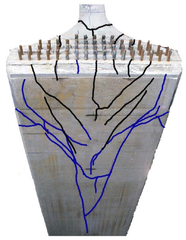
hazardous type of cracks in the PC girder is a Y-shaped patterned crack, which is often observed in the junction of the bottom flange and the web, as it can trace through the bottom flange (Fig. 2). This type of crack is usually governed by the strand distribution or the eccentricity of strands in the bottom flange [21].
Fig. 2- Longitudinal splitting cracks on bottom of a PC girder [22].
The cracks that are formed in the end-region of a PC girder can act as pathways for chlorides to reach into a girder and eventually to the steel reinforcement. This may lead to reinforcement corrosion that can cause even further cracking in PC members [13]. When there is a severe cracking in PC girders, the bond between the concrete and the reinforcement is weakened. This reduced bond is one of the primary reasons for the strength loss in the girder [14]. Regardless of the climate issue, the complex state of stress and the severity of end-region cracking can be mitigated at the designing stage by optimizing the use of reinforcement, concrete strength, level of prestressing force, and the depth of a girder [12].
3. REPAIR, RETROFIT AND PROVENTIONOF END-REGION CRACKS
Table 1 summarizes some of the methods that can be used for repair, retrofit, and prevention of formation and propagation of cracks in the end-region of PC girders. Some of these techniques are described subsequently.
Table 1. Typical waste/recycled plastics used in concrete.
Approach Methods References
Application of mortar Schupack and Suarez 1982 [23]; Nutzel et al. 1989 [24]; Garlock et al. 2012 [25]; Andrawes et al. 2018 [13]
Fiber-reinforced polymers
Repair and retrofit
Bassetti et al. 2000 [26]; Dolan et al. 2000 [27]; Kim et al. 2008 [28]; Ary and Kang 2012 [29]; ElSafty and Graeff 2012 [30]; Harik and Peiris 2013 [31]; Choo et al. 2013 [32]; Mohanamurthy and Yazdani 2015 [33]; Abdel-Mohti and Shen 2016 [34]; Shaw and Andrawes 2017 [35]; Belarbi et al. 2018 [36]; Frigione and Lettieri 2018 [37]; Peiris, Sun, and Harik 2018 [38]
International Journal of Civil and Structural Engineering Research ISSN 2348-7607 (Online) Vol. 7, Issue 1, pp: (134-145), Month: April 2019 - September 2019, Available at: www.researchpublish.com
Epoxy injection tubes Tadros et al. 2010 [12]; Ramseyer and Kang 2012 [39]; Shaw and Andrawes 2017 [35] Post-tensioning Pantelides et al. 2010 [40]; Burningham et al. 2011 [41]; Willis 2014 [7]
Prevention
3.1. Application of Mortar
Coating Treatment of PC Beam Ends
Stanish et al. 2001 [42]; Hosteng et al. 2015 [43] Strand debonding Abdalla et al. 1993 [44]; Hastak et al. 2003 [45]; Sousa et al. 2011 [46]; Burgueño and Sun 2011 [14]; Okumus and Oliva 2013 [21]; Ross et al. 2014 [22]; Naji and Ross 2017 [47]
One of the simplest ways to repair and retrofit the end-region cracking is to apply mortar to fill the cracks. Although the application of this method would cover the cracks, the mortar itself would not restore the strength loss of a cracked PC girder. However, the mortar application is thought to be helpful to prevent further deterioration or corrosion caused by chlorides penetrating through the cracks [23, 24, 13 and 25]. Overall, the application of mortar to the end-region cracks is not a robust repair method. It is rather considered as a temporary preventive measure against corrosion.
3.2. Fiber-Reinforced Polymers
An alternative repair method for the end-region cracks is to retrofit the cracked area with Fiber-Reinforced Polymers (FRP). FRP is a relatively new class of composite material and has gained an increasing popularity among the bridge engineering community due to its favorable mechanical characteristics and non-corrosive nature. Its high strength-toweight ratio is of true advantage since its dead load contribution is minimal, allowing a member strengthened with FRP to support larger live loads [48 and 49]. Some FRP composites (e.g., carbon FRP or CFRP) have approximately ten times higher tensile strength than the conventional steel and its strength is governed by its ability to sustain a load without an excessive deformation or failure [50]. In addition, its non-corrosive characteristics would eliminate the maintenance problems caused by moisture and chlorides.
FRP applied to the exterior side of a girder can act as a crack controller and would partially restore the shear strength in a girder [29]. Not only FRP increases the shear capacity of damaged PC girders, but also it would, if painted properly, improve the aesthetics of a structure and protect the reinforcement from corrosion [34]. Despite the high initial cost of FRPs, they are, if properly implemented and maintained, considered as a cost-effective long-term solution to avoid the need of having to frequently repair the end-region cracks of PC girders. Effectiveness of the FRP application would largely depend on factors such as a shear-span-to-depth ratio, and a configuration of the FRP.
As the shear span-to-depth-ratio increases, the shear capacity of a girder increases. For example, if two girders have the same amount of transversal reinforcement and FRP application, the increase in the shear capacity of one girder with a shear-span-to-depth ratio of four would be approximately twice of the girder with the ratio of three [29]. Transversal reinforcement itself is another factor that can impact the effectiveness of the FRP. Previous researches have shown that, in the presence of less transversal reinforcement, FRP became more effective. This is because of the stiffness inconsistency between the transversal reinforcement and FRP [29 and 35].
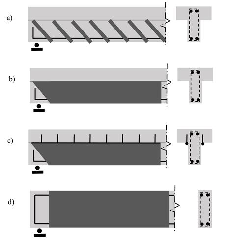
Figure 3 shows four different configurations of FRP wraps. One of the most effective ways for increasing the failure load would be to fully wrap the girder with CFRP. When using this method, a member’s load carrying capacity increased from 25% to 40% compared to a damaged girder [30, 35 and 33]. The failure mechanism of girders depends on the configuration of wrapping. When strips of FRP are used, the failure mode is debonding; whereas, through the application of continuous U-wrapping, the failure mode is a splitting of concrete [29 and 37]. The configuration of the FRP on PC girders also plays a role in the translations of forces at the fixed ends. A study by Choo et al. [32] monitored translations of the girder ends and showed that when the FRP was applied horizontally to the girder, the horizontal translation of the
International Journal of Civil and Structural Engineering Research ISSN 2348-7607 (Online) Vol. 7, Issue 1, pp: (134-145), Month: April 2019 - September 2019, Available at: www.researchpublish.com
girder decreased. However, the vertical wrapping of FRP did not have any impact on the vertical translation of the girder.
Fig. 3- FRP wrapping configurations, a) side bonding, b) U wrapping, c) U wrapping with anchorage, d) Fully wrapping.
Ramseyer and Kang [39] investigated the effectiveness of current and potential repair techniques for the end-region of damaged AASHTO prestressed concrete girders. The authors used FRP wraps and near surface mounted rods in repairing and strengthening the damaged AASHTO girders. Full-scale Type II AASHTO girders were prepared and tested before and after the girders were repaired. The test results indicated that the application of CFRP provided the greatest amount of stiffness recovery while the highest percentage of overall strength recovery was obtained by using glass FRP (GFRP).
While numerous researches have shown that the application of FRP is an effective way to repair the damaged ends of girders, one of the issues that have been noted through observation was that the FRP may be unbonded to the concrete over time, leading to a delamination around the edges of the application area. This delamination, however, is insignificant to overall effects of structural integrity in PC girders [32]. Accessibility to the damaged regions is another challenge for retrofitting PC girders using FRP since fully wrapping a girder may not be possible if a concrete deck is placed on top of a girder [38 and 31].
3.3. Epoxy Injection
One of the common crack repair methods used by engineers in multiple states and precast/prestressed fabricators for repairing end-region cracking is an epoxy injection method. Detailed information on the procedure and steps used in crack repair using the epoxy injection can be found in The PCI Manual for the Evaluation and Repair of Precast, Prestressed Concrete Bridge Products [51]. In recent studies by Shaw and Andrawes [35] and by Ramseyer and Kang [39], researchers investigated the effectiveness of injecting epoxy and applying FRP to the cracked region. In this type of application, epoxy is inserted into the cracks before FRP is installed to the damaged region. Test results indicated that the damaged girders repaired with both the epoxy and GFRP gained more shear and flexural strengths than the members repaired only with GFRP; 85% of its initial shear strength was restored when the girder was repaired only with GFRP while the shear strength of the damaged member repaired with both epoxy and GFRP was over 100% of its initial strength [39]. It was also found that the injection of epoxy improved overall stiffness and stability of the girder ends. In comparison between CFRP and GFRP, CFRP appeared not as effective as GFRP when they are used with epoxy.
Tadros et al. [12] reported that the tensile capacity of the damaged girder was not fully restored when it was repaired only with the epoxy injected into the cracks, which is an indication that the use of epoxy alone is not as effective as the
International Journal of Civil and Structural Engineering Research ISSN 2348-7607 (Online)
Vol. 7, Issue 1, pp: (134-145), Month: April 2019 - September 2019, Available at: www.researchpublish.com
application of both epoxy and FRP. One of the disadvantages of using epoxy alone over using both epoxy and FRP is that it would only strengthen the areas around the cracks where the epoxy is injected into. An issue may arise when the end cracks that occur during the force transfer are internal without showing external cracks through which epoxy can be injected. Even if the cracks are both external and internal, it may be difficulty to inject the epoxy such that it is fully penetrated into the internally cracked areas. If the entire cracked area is not properly filled with epoxy, it will not be as effective as what is originally intended or required. Thus, it is recommended that both epoxy and FRP be used to repair the damaged area [12].
3.4. Post-Tensioning
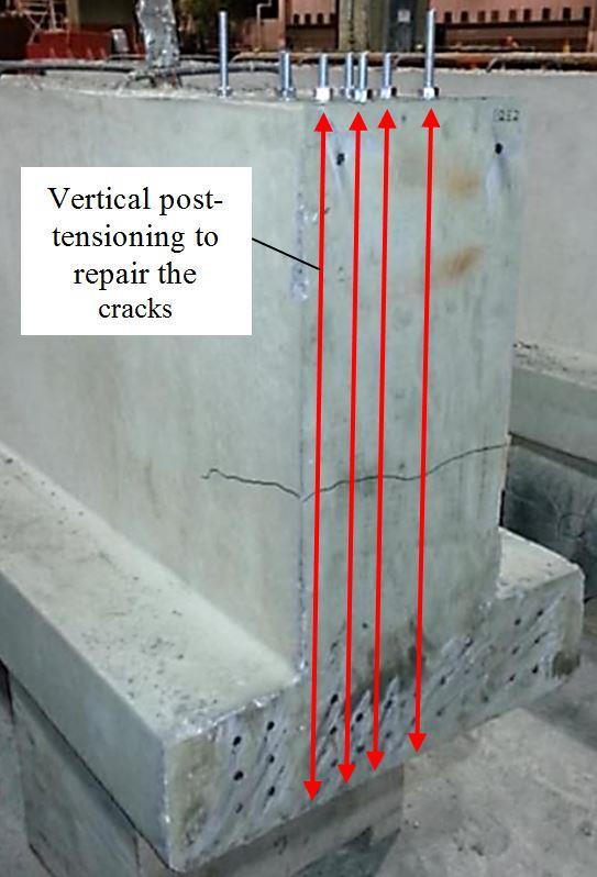
Another repair method for end-region cracking of PC girders is a post-tensioning. In a study by Willis [7], a vertical posttensioning using the turn-of-nut bolt tightening technique was applied to restore structural strength, decrease deflection, and increase the load carrying capacity of PC girders (Fig. 4) that were damaged due to web-splitting cracks during and immediately after prestress transfer. The results of the laboratory investigation revealed that the rods with smaller diameters (0.25 in. or 6.35 mm) were not as effective and cost-effective as the larger rods (0.375 in. or 9.53 mm, and 0.5 in. or 12.7 mm). The vertical post-tensioning (4.3% of jacking prestressing value) resulted in a reduction of crack width and length by 55% compared to control specimens. The study also showed that, when the post-tensioning was removed after 220 days, the concrete strain increased in tension, which led to a growing of cracks in width and length, indicating that the threaded rods used for post-tensioning were effective for restraining the end-region crack growths of the damaged PC girders [7].
Fig. 4- Vertical post-tensioning repair for end-region cracks [7].
In recent years, the method of using CFRP rods for post-tensioning has become more popular due to their lightweight, high tensile strength, and resistance to corrosion [41]. In a typical application, CFRP rods are placed horizontally in rows on each side of the web and secured with clamp anchors followed by post-tensioning the rods using a mechanical stressing device (e.g. hydraulic jack). A study reported that the ultimate load carrying capacity and the overall stiffness of a girder strengthened by the CFRP post-tensioning increased by approximately 20% and 5%, respectively [40].
3.5. Beam-End Treatment
Hosteng et al. [43] conducted a research to investigate the resistance of various beam coating alternatives against chloride penetration through the end-region cracks of PC girders. The selection of coating materials was made based on literature reviews and input from the Iowa Department of Transportation. The concrete ponding specimens were prepared and the selected coating alternatives were evaluated in accordance with AASHTO T259-80, chloride ion penetration test [42]. Each coating material was applied to a designated section (Fig. 5) on the slab while two sections were left uncoated as
International Journal of Civil and Structural Engineering Research ISSN 2348-7607 (Online) Vol. 7, Issue 1, pp: (134-145), Month: April 2019 - September 2019, Available at: www.researchpublish.com
controls. Test results revealed that the coated sections showed a better resistance against the chloride penetration of the concrete than the uncoated sections. Based on the ponding data, the best to worst performance of coating alternatives were as follows: (1) three-way tie: BASF Sonoguard, BASF Hydrozo 100, and Sikagard 62 – two coats; (2) Viking Aqua Guard Concrete Sealer; (3) Sikagard 62 – one coat; (4) TEX•COTE RAINSTOPPER 140; (5) PAULCO TE-3008-1; (6) Evercrete DPS; and (7) TEX•COTE XL 70 BRIDGE COTE with Silane [43].
Additionally, Hosteng et al. [43] investigated alternative beam-end forming details that were developed to reduce an exposure of the strand ends to the elements and mitigate the beam end deterioration due to corrosion. Four alternative fabrication details were developed and evaluated, including: single and double beam-end block-outs (Fig. 6), individual block-out, and drilling-out of strands. Among these alternatives, the single, double and individual bar block-outs appeared to be viable beam-end fabrication alternatives in terms of constructability and effectiveness in creating void between the strand end and the vertical face of the beam end. The drilling-out method was not considered be viable due to its difficulty of drilling out the strands, especially after each strand was flush cut to the beam face. Foam was found to be a preferable material over wood and metal for creating the voids since it doesn’t require chamfering the edges of the block-out and that the removal of the end formwork was similar to a standard beam.
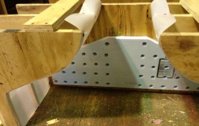
Fig. 5- Coating treatment application on a ponding slab [43].
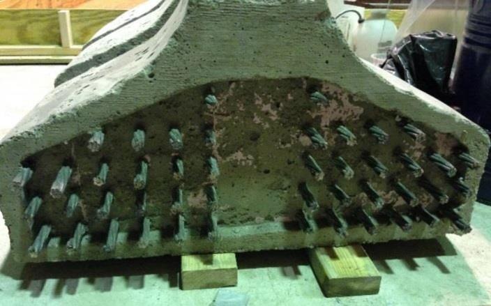
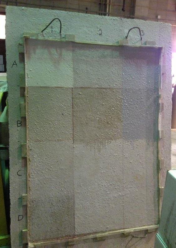
Fig. 6- Single Blockout formed with 1 in. foam [43].
3.6. Strand Debonding
Strand debonding is a prevention technique that can be used to reduce the prestressing force applied to the ends of PC girders. Strand debonding can be done by wrapping a plastic sheath or plastic tube around the prestressing strands. In a PC girder, when the stress is transferred from the strands to the girder, a considerable amount of stress is transferred to the ends of girders. During this process, the bending moment due to the eccentricity of prestressing force is increased, which
International Journal of Civil and Structural Engineering Research
ISSN 2348-7607 (Online) Vol. 7, Issue 1, pp: (134-145), Month: April 2019 - September 2019, Available at: www.researchpublish.com
can create a tensile stress in the top region of the cross-section. Meanwhile, debonding of strands would decrease both the flexural and shear capacity of a girder, which might lead to a creation of cracks in the debonded region [45 and 46]. However, this crack can be mitigated or prevented through adjusting the length of debonding [44]. While numerous researches have shown that the strand debonding method is somewhat effective in reducing cracks at the end-region of PC girders, it should be noted that it does not provide a complete solution to the issue. If debonding is excessive, it may create more problems than what it solves [44]. Debonded length, number of debonded strands, and release pattern of the prestressing strands are influential on the effectiveness of the debonding method [14, 21, 22 and 47]. In order to prevent end-region cracks induced by excessive debonding, AASHTO [52] has set a standard to design that limits the above mentioned factors.
4. SUMMARY AND CONCLUDING REMARKS
While PC girders have been considered as an economical and high performance alternative in bridge construction for many years, the end-region cracks of these girders have become prevalent in recent years with the use of relatively high strength concrete, deep girders, and high prestressing force. Numerous repair and prevention techniques have been proposed and investigated in this field such as an application of mortar, fiber-reinforced polymers wrapping, epoxy injection, post-tensioning, and strand debonding. This paper presented a methodical review on the current body of knowledge discussing various methods to repair and retrofit, and prevent the formation and propagation of end-region cracks in PC girders. The following remarks are drawn from this study:
The application of mortar to the end-region cracks is not a robust repair method but more of a temporary method to repair cracks and a preventive measure against corrosion.
The application of FRP wrapping around the end-region of PC girders improves the structural behavior of damaged PC girders, and helps prevent rebar corrosion.
The use of both FRP and epoxy injection is more effective than the application of epoxy injection alone. Some studies indicated that the shear capacity of a damaged girder was fully restored with this technique.
The application of post-tensioning technique in the end-region of PC girders is an effective method to close the cracks and increases the shear capacity of PC members with end-region cracks.
Coating treatment to the end-region of PC girders is an effective preventive alternative against chloride penetration.
Strand debonding can be somewhat effective in reducing cracks at the end-region of PC girders. However, care should be taken since it may create more problems than what it solves if debonding is excessive.
Since the cause and the severity of end-region cracks are relatively different in most cases, it is noted that in-service PC girders be inspected and carefully examined, and the ramification of any observed be studied prior to selecting any repair/prevention technique. In doing so, more realistic damage may be simulated in the analytical/experimental program; and the most effective repair/strengthening and damage prevention system may be formulated, tested, and developed.
REFERENCES
[1] ASCE’s 2017 Infrastructure Report Card | GPA: D+.‖ n.d. ASCE’s 2017 Infrastructure Report Card. Accessed September 15, (2017). http://www.infrastructurereportcard.org.
[2] Federal Highway Administration (FHWA). (2011). ―Bridge Preservation Guide. Rep. No. FHWA-HIF-11042.‖ US Department of Transportation.
[3] Boulfiza, M., Sakai, K., Banthia, N., and Yoshida, H. (2003). ―Prediction of Chloride Ions Ingress in Uncracked and Cracked Concrete.‖ ACI Materials Journal 100 (1).
[4] Cady, P. D., and Weyers, R. E. (1984). ―Deterioration Rates of Concrete Bridge Decks.‖ Journal of Transportation Engineering 110 (1): 34–44.
[5] Climent, M. A., Guillem de Vera, López, J. F., Viqueira, E., and Andrade, C. (2002). ―A Test Method for Measuring Chloride Diffusion Coefficients through Nonsaturated Concrete: Part I. The Instantaneous Plane Source Diffusion Case.‖ Cement and Concrete Research 32 (7): 1113–1123.
International Journal of Civil and Structural Engineering Research ISSN 2348-7607 (Online) Vol. 7, Issue 1, pp: (134-145), Month: April 2019 - September 2019, Available at: www.researchpublish.com
[6] Yeager, C., M. (2007). ―Corrosion of Prestressing Strands Used to Construct Bridge Girders.‖ PhD Thesis, University of Oklahoma.
[7] Willis, M. (2014). ―Post-Tensioning to Prevent End-Region Cracks in Pretensioned Concrete Girders.‖
[8] Uijl, J. A. D. (1983). Tensile Stresses in the Transmission Zones of Hollow Core Slabs Prestressed with Pretensioned Strands. Delft University of Technology, Department of Civil Engineering.
[9] Weyers, R. E., Prowell, B. D., Sprinkel, M. M., and Vorster, M. (1993). ―Concrete Bridge Protection, Repair, and Rehabilitation Relative to Reinforcement Corrosion: A Methods Application Manual.‖ Contract 100: 103.
[10] Freeman, J. C.,. Haller, S. A., Hansen, D. M., Weitze, J. A., and Martini, K. J. (1999). ―Seacoast Fortifications Preservation Manual.‖ San Francisco, CA.: National Park Service & KEA Environmental–GGNRA.
[11] Emmons, P. H., and Emmons, B. W. (1994). ―Concrete Repair and Maintenance Illustrated: Problem Analysis.‖ Repair Strategy, Techniques RS Means Company (October, 1994)
[12] Tadros, M. K., Badie, S. S and Tuan, C. Y. (2010). Evaluation and Repair Procedures for Precast/Prestressed Concrete Girders with Longitudinal Cracking in the Web. Vol. 654. Transportation Research Board.
[13] Andrawes, B., Shaw, I. D., and Zhao, H. (2018). ―Repair & Strengthening of Distressed/Damaged Ends of Prestressed Beams with FRP Composites.‖ Illinois Center for Transportation.
[14] Burgueño, R., and Sun, Y. (2011). ―Effects of Debonded Strands on the Production and Performance of Prestressed Concrete Beams.‖
[15] Hasenkamp, C. J., Badie, S. S., Tuan, C. Y., and Tadros, M. K. (2008). ―Sources of End Zone Cracking of Pretensioned Concrete Girders.‖
[16] Marshall, W. T.,and Mattock, A. H. (1962). Control of Horizontal Cracking in the Ends of Pretensioned Prestressed Concrete Girders. Portland Cement Association, Research and Development Laboratories.
[17] Mirza, J. F., and Tawfik, M. E. (1976). ―End Cracking in Prestressed Members during Detensioning.‖
[18] Kannel, J., French, C., and Stolarski, H. (1997). ―Release Methodology of Strands to Reduce End Cracking in Pretensioned Concrete Girders.‖ PCI Journal 42 (1).
[19] Crispino, E. D., Cousins, T. E., and Roberts-Wollmann, C. L. (2009). ―Anchorage Zone Design for Pretensioned Precast Bulb-T Bridge Girders in Virginia.‖ Virginia Center for Transportation Innovation and Research.
[20] Tuan, C. Y., Yehia, S. A., Jongpitaksseel, N., and Tadros, M. K. (2004). ―End Zone Reinforcement for Pretensioned Concrete Girders.‖ PCI Journal 49 (3): 68.
[21] Okumus, P, and Oliva, M. G. (2013). ―Evaluation of Crack Control Methods for End Zone Cracking in Prestressed Concrete Bridge Girders.‖ PCI Journal 58 (2).
[22] Ross, B. E., Hamilton, H. R., and Consolazio, G. R. (2014). ―Experimental Study of End Region Detailing and Shear Behavior of Concrete I-Girders.‖ Journal of Bridge Engineering 20 (6): 04014087.
[23] Schupack, M, and Suarez, M. G. (1982). ―Some Recent Corrosion Embrittlement Failures of Prestressing Systems in the United States.‖ PCI Journal 27 (2): 38–55. https://doi.org/10.15554/pcij.03011982.38.55.
[24] Nutzel, O., Zimmermann, E., and Jungwirth, D. (1989). Corrosion protected tension member for use in prestressed concrete and method of installing same. United States US4878327A, filed March 14, 1988, and issued November 7, 1989. https://patents.google.com/patent/US4878327A/en.
[25] Garlock, M., Paya-Zaforteza, I., Kodur, V., and Gu, L. (2012). ―Fire Hazard in Bridges: Review, Assessment and Repair Strategies.‖ Engineering Structures 35 (February): 89–98. https://doi.org/10.1016/j.engstruct.2011.11.002.
[26] Bassetti, A., Nussbaumer, A., and Colombi, P. (2000). ―Repair of Riveted Bridge Members Damaged by Fatigue Using CFRP Materials.‖ Advanced FRP Materials for Civil Structures 19: 33–42.
Publish Journals
International Journal of Civil and Structural Engineering Research ISSN 2348-7607 (Online) Vol. 7, Issue 1, pp: (134-145), Month: April 2019 - September 2019, Available at: www.researchpublish.com
[27] Dolan, C. W., Hamilton, H. R., Bakis, C. E., and Nanni, A. (2000). ―Design Recommendations for Concrete Structures Prestressed with FRP Tendons, Final Report.‖ Department of Civil and Architectural Engineering Report DTFH61-96-C-00019, University of Wyoming, Laramie, Wyo., May
[28] Kim, Y. J., Green, M. F., and Fallis, G. J. (2008). ―Repair of Bridge Girder Damaged by Impact Loads with Prestressed CFRP Sheets.‖ Journal of Bridge Engineering 13 (1): 15–23.
[29] Ary, M. I., and Kang, T. H-K. (2012). ―Shear-Strengthening of Reinforced & Prestressed Concrete Beams Using FRP: Part I Review of Previous Research.‖ International Journal of Concrete Structures and Materials 6 (1): 41–47.
[30] ElSafty, A., and Graeff, M. K. (2012). ―The Repair of Damaged Bridge Girders with Carbon Fiber Reinforced Polymer" CFRP" Laminates.‖
[31] Harik, I. E., and Peiris, A. (2013). ―DEPLOYMENT OF FRP MATERIALS IN BRIDGES IN KENTUCKY, USA.‖
[32] Choo, C. C., Peiris, A., and Harik, I. E. (2013). ―Repair of I-65 Expressway Bridges Using Carbon Fiber Reinforced Polymer (CFRP) Composites.‖
[33] Mohanamurthy, M., and Yazdani, N. (2015). ―Flexural Strength Prediction in FRP Strengthened Concrete Bridge Girders.‖ European Journal of Advances in Engineering and Technology 2 (3): 59–68.
[34] Abdel-Mohti, A., and Shen, H. (2016). ―Strengthening of Corroded Reinforced SCC-RAP Members with CFRP.‖ Fibers 4 (1): 3.
[35] Shaw, I., and Andrawes, B. (2017). ―Repair of Damaged End Regions of PC Beams Using Externally Bonded FRP Shear Reinforcement.‖ Construction and Building Materials 148: 184–194.
[36] Belarbi, A., M. Reda, P. P., Tahsiri, H., Dawood, M., and Gencturk, B. (2018). ―Prestressing Concrete with CFRP Composites for Sustainability and Corrosion-Free Applications.‖ In MATEC Web of Conferences, 149:01010. EDP Sciences.
[37] Frigione, M., and Lettieri, M. (2018). ―Durability Issues and Challenges for Material Advancements in FRP Employed in the Construction Industry.‖ Polymers 10 (3): 247.
[38] Peiris, A., Sun, C., and Harik, I. (2018). ―Lessons Learned from Six Different Structural Health Monitoring Systems on Highway Bridges.‖ Journal of Low Frequency Noise, Vibration and Active Control, 1461348418815406.
[39] Ramseyer, C., and Kang, T. H-K. (2012). ―Post-Damage Repair of Prestressed Concrete Girders.‖ International Journal of Concrete Structures and Materials 6 (3): 199–207.
[40] Pantelides, C. P., Reaveley, L. D., and Burningham, C. A. (2010). ―Repair of Prestressed Concrete Girder Ends and Girder Collision Repair.‖
[41] Burningham, C. A., Pantelides, C. P, and Reaveley, L. D. (2011). ―Prestressed Concrete Girder Repair with CFRP Post-Tensioned Rods.‖ In 10th International Symposium on Fiber-Reinforced Polymer Reinforcement for Concrete Structures 2011, FRPRCS-10, in Conjunction with the ACI Spring 2011 Convention
[42] Stanish, K. D., Hooton, R. D., and Thomas, M. D. (2001). ―Testing the Chloride Penetration Resistance of Concrete: A Literature Review.‖ United States. Federal Highway Administration.
[43] Hosteng, T., Abu-Hawash, A., Port, G., and Phares, B.M. (2015). ―Laboratory Investigation of Concrete Beam-End Treatments.‖
[44] Abdalla, O. A., Ramirez, J. A., and Lee, R. H. (1993). ―Strand Debonding in Pretensioned Beams-Precast Prestressed Concrete Bridge Girders with Debonded Strands-Continuity Issues.‖
[45] Hastak, M., Mirmiran, A., Miller, R., Shah, R., and Castrodale, R. (2003). ―State of Practice for Positive Moment Connections in Prestressed Concrete Girders Made Continuous.‖ Journal of Bridge Engineering 8 (5): 267–272.
[46] Sousa, C., Sousa, H., Neves, A. S., and Figueiras, J. (2011). ―Numerical Evaluation of the Long-Term Behavior of Precast Continuous Bridge Decks.‖ Journal of Bridge Engineering 17 (1): 89–96.
International Journal of Civil and Structural Engineering Research ISSN 2348-7607 (Online) Vol. 7, Issue 1, pp: (134-145), Month: April 2019 - September 2019, Available at: www.researchpublish.com
[47] Naji, B., and Ross, B. E. (2017). ―Evaluation of the AASHTO LRFD Strand Debonding Limitations in the Context of Bond-Loss Failure.‖ Journal of Structural Integrity and Maintenance 2 (1): 22–28.
[48] Youakim, S. A., and Karbhari, V. M. (2007). ―An Approach to Determine Long-Term Behavior of Concrete Members Prestressed with FRP Tendons.‖ Construction and Building Materials 21 (5): 1052–1060.
[49] Rosenboom, O., Hassan, T. K., and Rizkalla, S. (2007). ―Flexural Behavior of Aged Prestressed Concrete Girders Strengthened with Various FRP Systems.‖ Construction and Building Materials 21 (4): 764–776.
[50] Lee, Y.S., Wipf, T. J., Phares, B. M., and Klaiber, F. W. (2005). ―Evaluation of a Steel Girder Bridge Strengthened With CFRP Post-Tension Bars.‖ Journal of the Transportation Research Board, no. 1928: 233–44.
[51] PCI MNL-137. (2006). Bridge Repair Manual for the Evaluation and Repair of Precast, Prestressed Concrete Bridge Products. restressed Concrete Institute (PCI/CONCRT).
[52] AASHTO. (2014). ―AASHTO LRFD Bridge Design Specifications.‖ 7th ed. American Association of State Highway and Transportation.
