International Journal of Civil and Structural Engineering Research ISSN 2348-7607 (Online) Vol. 6, Issue 2, pp: (270-286), Month: October 2018 - March 2019, Available at: www.researchpublish.com
Strain Based Approach to the Modeling of Concrete under Uniaxial Tension-Tension Fatigue Loading
Indra Narayan Yadav1, Dr. Kamal Bahadur Thapa21Ph.D. Scholar, Department of Civil Engineering, Pulchowk Campus, Institute of Engineering, Tribhuvan University, Nepal
2Associate Professor, Department of Civil Engineering, Pulchowk Campus, Institute of Engineering, Tribhuvan University, Nepal
Corresponding emails: 1eecconsultant@gmail.com, 2kamal.thapa@ioe.edu.np
Abstract: Strain based Approach to the Modeling of Concrete under Uniaxial Tension-Tension Fatigue Loading is briefly described regarding Stiffness degradation and inelastic deformation which are the essential features of concrete that develop due to the formation of multitude of microcracks in the fatigue environment. Microcracking, which is anisotropic in nature, destroys the bond between material grains, and affects the elastic properties resulting in the reduction of material stiffness. This paper presents Strain based Approach to the Modeling of Concrete under Uniaxial Tension-Tension Fatigue Loading. The model is developed, in strain space, using the general framework of internal variable theory of continuum thermodynamics. It is argued that within the damage surface of given strain states the unloading-reloading cycles (fatigue loading) stimulate the nucleation and growth microcracks in concrete, which will result in stiffness degradation and inelastic deformation, and hence material is termed as damaged. Damage is reflected through the fourth-order stiffness tensor involving a damage parameter whose increment is governed by the consistency equation associated with a cycle dependent damage surface in strain space. The model is capable of predicting stiffness degradation, inelastic deformation and strength reduction under fatigue loading and compared against experimental results.
Keywords: Fatigue; uniaxial; damage; Concrete; Thermodynamics; stiffness; microcracks, response tensors.
1. INTRODUCTION
In recent times, concrete has become the bedrock of infrastructural civilization in Nepal. Statistics has shown that over 75% of the infrastructures in Nepal have to do with concrete. Thus, it is important to study and understand every aspect of concrete from the production, transportation, placing and eventually maintenance of concrete.
Concrete today has a very wide range of applications. Virtually every civil engineering work in Nepal today is directly or indirectly involving the use of concrete. The use of concrete in civil engineering works includes: construction of residential houses, industrial warehouses, roads pavement construction, Shore Protection works, piles, domes, bridges, culverts, drainages, canals, dams etc. (Shetty, 2005; Neville, 2011; Edward and David, 2009; Duggal, 2009; Gambhir, 2005). In Nepal, the cases of failure of structures and roads (concrete related failure) occur on a yearly basis.
Concrete is one of the most widely used materials in numerous civil engineering applications due to its workability and formability into various structural components. Except cement all ingredients of concrete are commonly available local materials like aggregate and water so concrete is getting more popular. Concrete is a composite material consisting of three components: the cement matrix, the aggregate and the interface between the matrix and aggregate. The cementmatrix is the weakest zone of the composite. It contains voids and micro cracks even before any load has been applied. A material or a component exposed to cyclic loading leads to increase of stress concentration around the micro cracks and
International Journal of Civil and Structural Engineering Research ISSN 2348-7607 (Online) Vol. 6, Issue 2, pp: (270-286), Month: October 2018 - March 2019, Available at: www.researchpublish.com
finally leads to fracture. Forces that are required to obtain the fracture in cyclic loading are usually much less than forces that would have been required in case of monotonic loading. Phenomenon that deals with this type of fracture is called fatigue. It is caused by progressive, permanent internal structural changes in the material, which may result in micro cracks and their propagation until governing macro cracks are formed. The effect of cyclic loading is to develop permanent damage in the concrete materials as a result of which failure happens under the stress having value less than the ultimate strength of concrete. Concrete, a heterogeneous material comprising the mixture of cement, sand and aggregate, exhibits several mutually interacting inelastic mechanisms such as micro crack growth and inelastic flow even under small amplitude of cyclic load when applied in large number of cycles. As a consequence, concrete does not guarantee endurance fatigue limit like metal as described in Miner’s hypothesis.
Reinforced concrete structures such as bridges, hydraulic foundations, pressure vessels, crane beams are subjected to long term cyclic loading. The effect of cyclic loading is to develop permanent damage in the concrete materials as a result of which failure happens under the stress having value less than the ultimate strength of concrete. Concrete, a heterogeneous material comprising the mixture of cement, sand and aggregate, exhibits several mutually interacting inelastic mechanisms such as microcrack growth and inelastic flow even under small amplitude of cyclic load when applied in large number of cycles. As a consequence, concrete does not guarantee endurance fatigue limit like metal as described in Miner’s hypothesis [1].
The presence of permanent damage at fatigue failure has been documented by a number of investigations. [2] developed fatigue damage model for ordinary concrete subjected to cyclic compression based on mechanics of composite materials utilizing the concept of dual nature of fatigue damage, which are cycle dependent and time dependent damage. The model was capable of capturing the cyclic behavior of plain concrete due to progressive creep strain with the increase in number loading cycles. [3] used accelerated pavement testing results for carrying out cumulative fatigue damage analysis of concrete pavement. In [3], they reported that Miner hypothesis does not accurately predict cumulative fatigue damage in concrete. The experimental work of [4] clearly showed that increase of damage in the material takes place in about last 20% of its fatigue life. [5] presented a theoretical model to predict the fatigue process of concrete in alternate tensioncompression fatigue loading using double bounding surface approach described in strain-energy release rate by constructing the damage-effective tensor.
In the past few years, a number of damage constitutive models have been published to model the observed mechanical behavior of concrete under monotonic and cyclic loading ([6], [7], [8], [9], and [10]). The need for such models arises from the physical observation that two dominant microstructural patterns of deformation in concrete are inelastic flow and microcracking. The inelastic flow component of deformations is modeled by using plasticity theories whereas the nucleation and propagation of microcracks and microvoids is incorporated in the constitutive models with the use of damage mechanics theories. The progressive development of cracks and microcracks alters the elastic properties (degradation of elastic moduli) due to energy dissipation and concrete material becomes more compliant.
This paper presents a class of damage mechanics theory to model the fatigue damage and failure of concrete caused by multitude of cracks and microcracks whereby anisotropic damaging behavior is captured through the use of proper response function involving damage parameter in material stiffness tensor. The increment of damage parameter is obtained from consistency equation in cycle dependent damage surface in strain space. The model is also capable of capturing the inelastic deformations that may arise due to misfits of crack surfaces and development of sizable crack tip process zone.
2. FORMULATION
In this paper, it is assumed that a continuum damage mechanics approach can be taken to describe the constitutive relation for concrete and that the fatigue loading is of low frequency so that the thermal effects could be ignored. For isothermal process, rate independent behavior and small deformations, the Helmholtz Free Energy (HFE) per unit volume can be deduced from [11] and shown as follows:
International Journal of Civil and Structural Engineering Research ISSN 2348-7607 (Online) Vol. 6, Issue 2, pp: (270-286), Month: October 2018 - March 2019, Available at: www.researchpublish.com
Where E (k) represents fourth order elastic stiffness tensor which depends on the state of microcracking (damage), ε is the strain tensor, i σ denotes the stress tensor corresponding to inelastic damage. The term represents surface energy of microcracks [12], and k is the cumulative fatigue damage parameter. The colon (:) represents the tensor contraction operation.
For an inelastic damaging process, a constitutive relation between the stress and strain tensors can be established utilizing fourth order material’s stiffness tensor as
.....(2)
The rate form of Eqn (2) with respect to cyclic number N is given by
.....(3)
Where e σ is the stress increment in the absence of further damage in the material, D σ is the rate of stress-relaxation due to further microcracking (elastic damage), and k i σ designates the rate of stress tensor corresponding to irrecoverable or permanent deformation due to microcracking.
It is further assumed that damage during fatigue loading alters elastic properties and affects the stiffness tensor. For small deformation, the following decomposition of the fourth-order stiffness tensor, E, is adopted
Where 0E is stiffness of the undamaged or virgin material and k DE denotes the overall stiffness degradation caused by damage during fatigue loadings. Further, k E and k i σ are expressed as fluxes in the thermodynamic state sense and are expressed in terms of evolutionary equations as M σ L ED k and k
Where L and M are, respectively, fourth and second order response tensors that determine the directions of the elastic and inelastic damage processes. Following the Clausius-Duhem inequality, utilizing the standard thermodynamic arguments [13] and assuming that the unloading is an elastic process, a potential function
(6) is obtained as damage surface which establishes the onset of material inelasticity and stiffness deterioration. In Eqn (6), k p ,ε is interpreted as the damage function given below as
for some scalar valued function
It should be noted that as long as the function k p , 2
is defined, the individual terms on the R.H.S of Eqn (7) need not to be identified.
To progress further, specific forms of response tensors L and M must be specified. Since damage is highly directional, the response tensors should be formulated to address such directionality. In determining a proper form for the response tensor, the strain tensor is decomposed into positive and negative cones. The positive and negative cones of the strain tensor hold the corresponding positive and negative eigenvalue of the system, that is,ε ε ε
. Here, ε andε represent the positive and negative cones of the strain tensor, respectively. Based on the experimental observations and results for concrete materials, damage is assumed to occur in the cleavage mode of cracking as shown schematically in Figure 1
International Journal of Civil and Structural Engineering Research ISSN 2348-7607 (Online) Vol. 6, Issue 2, pp: (270-286), Month: October 2018 - March 2019, Available at: www.researchpublish.com
Figure 1. Schematic representation of mode I damage (crack opening in tensile mode) under cyclic tension.
For cleavage cracking mode, the following forms of response tensors are postulated for L and M
.....(9)
The substitution of response tensors L and M from Eqns (8) and (9) into Eqn (6) leads to the final form of the damage surface
) ....(10 0 ,
For uniaxial tensile loading the damage surface of Eqn (10a) is rewritten as
The damage function p(k) obtained from uniaxial tensile test for concrete materials based on the experimental results of [14] is given in [15] as
) ...(10 0 , )
p
And for elastic damaging process, ( ), the limit damage surface reduces to
k (12)
Where u ε represents the strain corresponding to uniaxial tensile strength of concrete, which is used as the reference strain and hence the result of a conventional uniaxial tensile test is needed to establish u ε
3. FATIGUE DAMAGE MODEL
Fatigue loading is understood as the repeated or fluctuating strains acting in a material due to which progressive permanent structural change occurs in the form of cracks or flaws and the material fails at stresses having a maximum value less than the tensile strength of the material. In this paper, it is assumed that within the damage surface of the given strain state, the unloading-reloading cycles (Fatigue loadings) increase damage in concrete due to the growth of microcracks leading to inelastic deformations and stiffness degradation, which eventually reduces the ultimate strength of the concrete. To achieve this, the damage surface k ,ε is modified to predict the increase in damage in the material with increasing number of cycles of loading as
Where X(N) is a function that depends on the number of loading cycles and adopted to increase of damage with increasing number of cycles. We propose a power function for X(N) as
Here, N represents the number of loading cycles, and A is a material parameter Utilizing Eqns (11) through (14), we obtain the cumulative fatigue parameter k as
International Journal of Civil and Structural Engineering Research ISSN 2348-7607 (Online) Vol. 6, Issue 2, pp: (270-286), Month: October 2018 - March 2019, Available at: www.researchpublish.com
Finally, the rate of damage parameter, k , must be used in the simple constitutive relation of the form given by Eqn (3) in uniaxial tensile stress path for representing inelastic deformation, stiffness degradation and strength reduction due to fatigue cycles. Substituting Eqns (8), (9) and (16) into Eqn (5) and then substituting Eqns (4) and (5) into Eqn (3) yields
Eqn (17) is the rate of stress tensor for uniaxial tension-tension fatigue loading where it is assumed that unloading is elastic process. When , the process is classified as elastic-damaging, in which stress-strain curve returns to origin upon unloading of the material. In fact, damage incurred in concrete cannot be considered perfectly elastic. The unloaded material shows some residual strains due to the development of sizable crack tip process zone and misfits of the crack surfaces.
For uniaxial tension, Eqn (17) becomes
4. NUMERICAL EXAMPLES
The proposed model contains two material parameters, first is A which is factor related to materials intermolecular microcracks and second one is β which is called damage factor related to kinematic phenomena of the particle i.e. crack surface close perfectly after unloading. The damage parameter, k, which is regarded as the stiffness degradation in the proposed model, is computed by measuring stiffness at three different stages of loading cycle. The kinematic parameter, β, is determined by measuring the permanent deformation during one of the cyclic loadings. Due to the scarcity of experimental data in the literature for the measurement of these material parameters in the numerical simulation, analyst’s judgments are required to obtain numerical results.
The model prediction of modulus reduction with increasing number of cyclic loading is shown in Figure 3. Figure (6) and (7) shows the decrease of maximum stress level (S-N curve) in cyclic tension-tension loading. Figure (10) and (11) on other hand, shows corresponding experimental result regarding decrease of materials stress and increase of cumulative fatigue damage parameter with respect to increase of number of cyclic loading As may be seen, the model captures the relevant features of cyclic response.
International Journal of Civil and Structural Engineering Research ISSN 2348-7607 (Online) Vol. 6, Issue 2, pp: (270-286), Month: October 2018 - March 2019, Available at: www.researchpublish.com
Figure 2. Model prediction of stiffness reduction with number of cyclic loading. Adopting the Value of Fatigue Damage Parameter, A=0.10 and = 0.00
Figure 3. Model prediction of stiffness reduction with number of cyclic loading. Adopting the Value of Fatigue Damage Parameter, A=0.10 and = 0.15
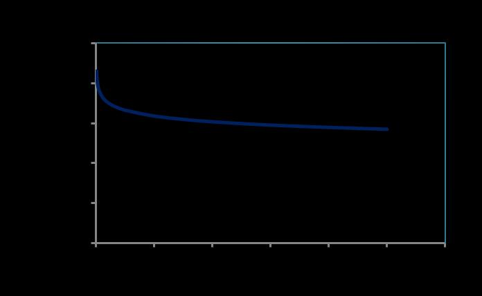
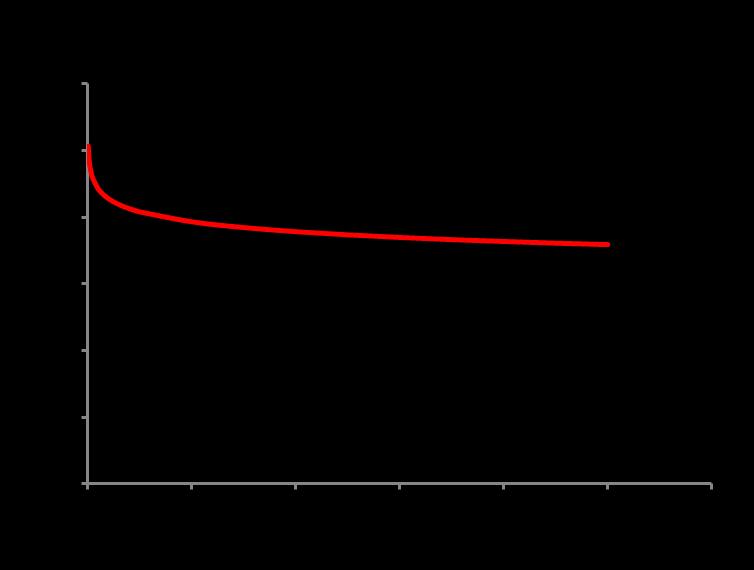
Figure 4. Model prediction of Damage Factor with number of cyclic loading. Adopting the Value of Fatigue Damage Parameter, A=0.10 and = 0.00

International Journal of Civil and Structural Engineering Research ISSN 2348-7607 (Online) Vol. 6, Issue 2, pp: (270-286), Month: October 2018 - March 2019, Available at: www.researchpublish.com
Figure 5. Model prediction of Damage Factor with number of cyclic loading. Adopting the Value of Fatigue Damage Parameter, A=0.10 and = 0.15
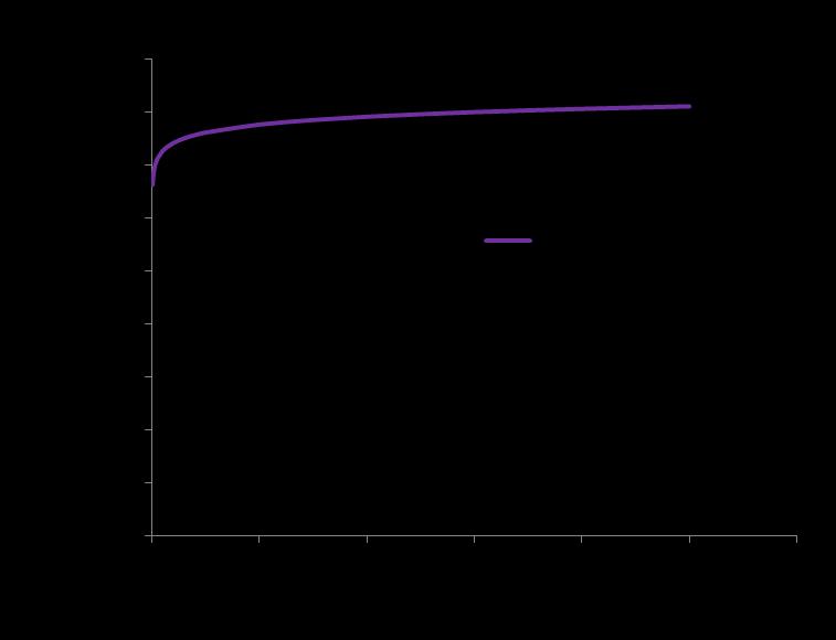
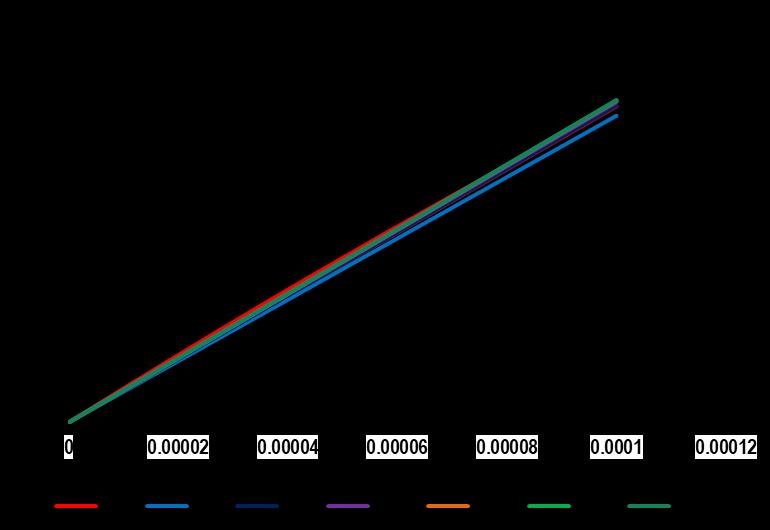

Figure 6. Theoretical cyclic stress-strain behavour of concrete during elastic damaging process under uniaxial fatigue loading. Adopting the Value of Fatigue Damage Parameter, A=0.10 and = 0.00
Figure 7. Theoretical cyclic stress-strain behavour of concrete during elastic damaging process under uniaxial fatigue loading. Adopting the Value of Fatigue Damage Parameter, A=0.10 and = 0.15
International Journal of Civil and Structural Engineering Research ISSN 2348-7607 (Online) Vol. 6, Issue 2, pp: (270-286), Month: October 2018 - March 2019, Available at: www.researchpublish.com
Figure 8. Model prediction of Maximum Stress Level verses Number of Cycle under uniaxial fatigue loading. Adopting the Value of Fatigue Damage Parameter, A=0.10 and = 0.00
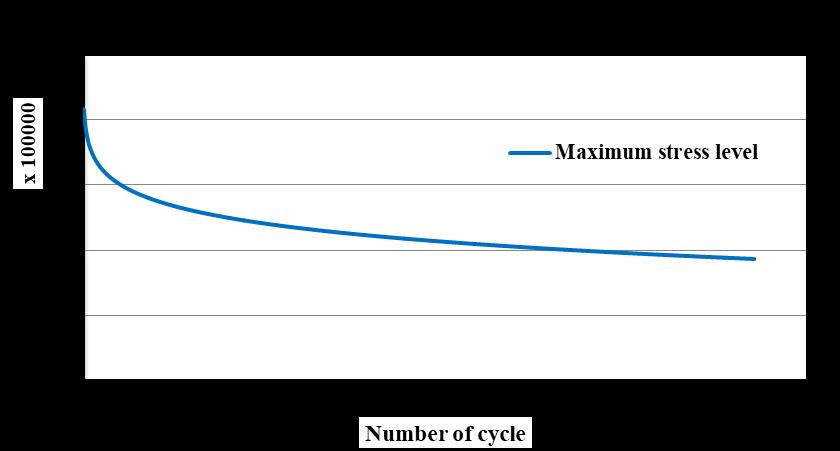

Figure 9. Model prediction of Maximum Stress Level verses Number of Cycle under uniaxial fatigue loading. Adopting the Value of Fatigue Damage Parameter, A=0.10 and = 0.15
Figure 10. Reduction in maximum stress level during cyclic tension. Prediction of the theory, Figure 8 and 9 by Peiyin Lu. Et. Al 2004

International Journal of Civil and Structural Engineering Research ISSN 2348-7607 (Online) Vol. 6, Issue 2, pp: (270-286), Month: October 2018 - March 2019, Available at: www.researchpublish.com
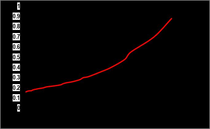
Figure 11. Variation of damage with the number of cyclic loading. Prediction of the theory, Figure (4) and Figure (5) Experimental Figure [11], by Peiyin Lu. Et. Al 2004
Figure (4) and (5) shows the increase in damage with increasing loading cycles. The experimental work of Figure [11] is also shown for comparison. The theoretical model also captures the similar trend of increasing damage with the cyclic loading as observed in the experiment [11]. For numerical simulation, the following constant were used, A = 0.10 and = 0.15 and 0.00 in two cases, Parameter A is estimated by comparing predicted results and experimental results over a range of applied strains.
Figures (6) and (7) depict the theoretical cyclical stress-strain behavior of concrete material in tension. In Figure 6, no permanent deformations are predicted to remain upon unloading of concrete material however progressive damage accumulation takes place in each loading cycle due to degradation of elastic modulus. This is the ideal case of elastic perfectly damaging behavior which can be achieved by letting with the assumption that crack surfaces close perfectly upon unloading. Heterogeneous materials like concrete exhibits permanent deformations. Figure 7 shows the versatile behavior of the model where the stiffness degradation and permanent deformation are illustrated simultaneously.
5. CONCLUSION
Strain Based Approach to the Modeling of Concrete under Uniaxial Tension-Tension Fatigue Loading of concrete materials during low frequency is presented by utilizing the framework of continuum thermodynamics of Continuum Mechanics by taking two material fatigue damage parameter i.e. A=fatigue damage Parameter regarding energy microcracks of the material particle and another is β=kinematic damage Parameter (phenomena of material crack surface close perfectly after unloading). Since the fatigue damage in concrete during the fatigue process is mainly due to development of microcracks and microvoids, a cycle dependend damage surface is employed in the formulation of this strain based theoretical model. Fatigue damage evolution law together with the damage response functions were used in the constitutive relation to demonstrate the capability of the model in capturing the essential features of concrete material, such as stiffness degradation and the inelastic deformations, under fatigue loading environment by finding out the cumulative fatigue damage parameter i.e. K. The fatigue curve relavant to A =0.10 and β =0.15 and 0.00 is generated by the modeling and after that this generated model curve is compared to the Curve obtained by Peiyin Lu. Et al (2004) which shows similar tread of generation of fatigue curve. This shows the good relation between results obtained from modeling and experiments also. Lower value in the experimental curve is due to 0.85 times maximum stress level whereas, modeling takes 100% value.
International Journal of Civil and Structural Engineering Research ISSN 2348-7607 (Online) Vol. 6, Issue 2, pp: (270-286), Month: October 2018 - March 2019, Available at: www.researchpublish.com
REFERENCES
[1] European Union – BriteEURamIII (2000) Fatigue of Normal Weight Concrete and Lightweight Concrete, Document BE 96-3942/R34.
[2] Duggal, S.K. (2009). “Building materials”. New Delhi, India. New Age International
[3] Edward, S. H. and David P. G., (2009). “Concrete construction”. Edward S. Hoffman, Ltd., Chicago.
[4] Gambhir, M .L. (2005) “Concrete technology”, Third edition Tata McGraw- Hill Publishing Company Limited, New Delhi.
[5] Neville A. M., (2011). “Properties of concrete”. Fifth edition. Pearson Publications, Harlow, England. UK.
[6] Shetty M. S., (2005). “Concrete technology: Theory and practice”. S. Chand & Company, Ram
[7] Szerszen, M.M. (2013) Fatigue damage model for ordinary concrete. Open journal of Functional Material Research (OJFMR), 1(2), 17-20
[8] Rao, S. and Roesler, J. (2004) Cumulative Fatigue Damage Analysis of Concrete Pavement using Accelerated Pavement Testing Results. In: Proceedings of the 2nd International Conference on Accelerated Pavement Testing, Minneapolis, Sep.
[9] Dyduch, K., Szerszen, M.M. and Destrebecq, J-F (1994) Experimental Investigation of the Fatigue Strength of Plain Concrete under High Compressive Loading. Structures and Materials, 27 (173), 505-509.
[10] L p., Li, Q., Song, Y. (2004) Damage Constitutive of Concrete under Uniaxial Alternate Tension-Compression Fatigue Loading Based on Double Bounding Surfaces International Journal of Solids and Structures, 41, 31523166.
[11] Fardis, M.N., Alibi, B. and Tassoulas, J.L (1983) Monotonic and Cyclic Constitutive Law for Concrete. J. Engrg, ASCE, 108EM2, 516-536
[12] Yang, B.L., Dafalias, Y.F., Herrmann, L.R. (1985) A Bounding Surface Plasticity Model for Concrete, Proc. Paper 19539. J. Engg. Mech , ASCE 111/EM3, 359-380
[13] Sauris, W., Ouyang, C., Fernando, V.M. (1990) Damage Model for Cyclic Loading for Concrete. J. Engg. Mech , ASCE 116(5), 1020-1035.
[14] Papa, E. (1993) A Damage Model for Concrete Subjected to Fatigue Loading. Eur.J. Mech.- A/solids, 12(3), 449440
[15] Khan, K.R., Al-Gadhib, A.H., Baluch, M.H (1998) An Elasto-Damage Constitutive Model for High Strength Concrete. In: Proceeding of the EURO-C 1998 Conference on computational model of concrete structure at Austria, March, 133-142
[16] Thapa, K B., Yazdani, S. (2013) Combined Damage and Plasticity Approach for Modeling Brittle Materials with Application to Concrete. International Journal of Civil and Structural Engineering, 3(3), 513-525.
[17] Chaboche, J.L. (1992) Damage Induced Anisotropy: On the Difficulties Associated with the Active/Passive Unilateral Conditions. Int. J. Damage Mechanics, 1, 148-171.
[18] Coleman, B.D. & Gurtin, M.E. (1967) Thermodynamics with International State Variables. J. Chem. Phys., 47(2), 597-613.
[19] Smith, G.M. & Young, L.E. (1955) Ultimate Theory in Flexure by Exponential Function. Proceedings of the American Concrete Institute, 52(3), 349-359.
[20] Thapa, K.B., Yazdani, S. (2014) A Strain Based Damage Mechanics Model for Plain Concrete. International Journal of Civil Engineering Research, 5(1), 27-40.
Table 1. Data Analysis for Fatigue Curve regarding Stiffness, Cumulative Damage Parameter Verses Number of Cycle of Concrete Assuming , Fatigue Damage Factor related to Surface Energy Microcracks i.e. A= 0.10 and Fatigue Kinematic Damage Factor (Crack Surface closed perfectly after unloading) i.e. β=0.00
1 0.1 0.00 2.34E+10 1E-04 2.718281828 0.367879 8608378923 0.632120559 14791621077
2 0.1 0.00 2.34E+10 1E-04 2.815852123 0.355132 8310095480 0.644867715 15089904520
3 0.1 0.00 2.34E+10 1E-04 2.876192321 0.347682 8135756372 0.652318104 15264243628
4 0.1 0.00 2.34E+10 1E-04 2.920554404 0.342401 8012177404 0.657599256 15387822596
5 0.1 0.00 2.34E+10 1E-04 2.955885852 0.338308 7916408539 0.661691943 15483591461
6 0.1 0.00 2.34E+10 1E-04 2.985369569 0.334967 7838225541 0.665033097 15561774459
7 0.1 0.00 2.34E+10 1E-04 3.010740403 0.332144 7772174570 0.667855788 15627825430
8 0.1 0.00 2.34E+10 1E-04 3.0330523 0.329701 7715000497 0.670299124 15684999503
9 0.1 0.00 2.34E+10 1E-04 3.052995299 0.327547 7664604006 0.67245282 15735395994
10 0.1 0.00 2.34E+10 1E-04 3.071046719 0.325622 7619551945 0.674378122 15780448055
20 0.1 0.00 2.34E+10 1E-04 3.194997641 0.312989 7323949068 0.687010724 16076050932
30 0.1 0.00 2.34E+10 1E-04 3.271916231 0.305631 7151772341 0.694368703 16248227659
40 0.1 0.00 2.34E+10 1E-04 3.328592706 0.300427 7029997981 0.699572736 16370002019 50 0.1 0.00 2.34E+10 1E-04 3.373807035 0.296401 6935784933 0.703598934 16464215067 60 0.1 0.00 2.34E+10 1E-04 3.411588452 0.293119 6858975029 0.706881409 16541024971 70 0.1 0.00 2.34E+10 1E-04 3.444135968 0.290349 6794156857 0.709651416 16605843143 80 0.1 0.00 2.34E+10 1E-04 3.472786939 0.287953 6738104126 0.712046832 16661895874 90 0.1 0.00 2.34E+10 1E-04 3.498417763 0.285844 6688738048 0.714156494 16711261952 100 0.1 0.00 2.34E+10 1E-04 3.521635146 0.283959 6644640638 0.716040998 16755359362 200 0.1 0.00 2.34E+10 1E-04 3.681503839 0.271628 6356098221 0.728371871 17043901779 300 0.1 0.00 2.34E+10 1E-04 3.781094589 0.264474 6188684110 0.73552632 17211315890 400 0.1 0.00 2.34E+10 1E-04 3.854660161 0.259426 6070574065 0.740573758 17329425935 500 0.1 0.00 2.34E+10 1E-04 3.913457797 0.255528 5979366896 0.7444715 17420633104 600 0.1 0.00 2.34E+10 1E-04 3.962663371 0.252356 5905119312 0.747644474 17494880688 700 0.1 0.00 2.34E+10 1E-04 4.005105817 0.249681 5842542263 0.750318707 17557457737 800 0.1 0.00 2.34E+10 1E-04 4.042507649 0.247371 5788486265 0.752628792 17611513735 900 0.1 0.00 2.34E+10 1E-04 4.075998823 0.245339 5740924131 0.754661362 17659075869 1000 0.1 0.00 2.34E+10 1E-04 4.106362272 0.243525 5698474331 0.756475456 17701525669
International Journal of Civil and Structural Engineering Research ISSN 2348-7607 (Online) Vol. 6, Issue 2, pp: (270-286), Month: October 2018 - March 2019, Available at: www.researchpublish.com
Table 2. Data Analysis for Fatigue Curve regarding Stiffness, Cumulative Damage Parameter Verses Number ofCycle ofConcrete
Assuming , Fatigue Damage Factor related to Surface Energy Microcracks i.e. A= 0.10 and Fatigue Kinematic Damage Factor(Crack Surface closedperfectly afterunloading)i.e. β=0.15
N (Number ofCycle)
Fatigue Damage Parameter (A)
Stiffness factor(β) E0 εu Exp(sqrt((12xβ)xN^Axε uxεu)/εu)
(E0k)/E0 (Eo-k) 1-((E0k)/E0) Fatigue Damage Parameter, K
1 0.1 0.15 2.34E+10 1E-04 2.308643278 0.433155 10135823157 0.566845164 13264176843
2 0.1 0.15 2.34E+10 1E-04 2.377774054 0.420561 9841136907 0.579438594 13558863093
3 0.1 0.15 2.34E+10 1E-04 2.420330174 0.413167 9668102415 0.58683323 13731897585
4 0.1 0.15 2.34E+10 1E-04 2.451524347 0.407909 9545081625 0.592090529 13854918375
5 0.1 0.15 2.34E+10 1E-04 2.476313066 0.403826 9449532179 0.596173839 13950467821
6 0.1 0.15 2.34E+10 1E-04 2.496961949 0.400487 9371388303 0.59951332 14028611697
7 0.1 0.15 2.34E+10 1E-04 2.514703724 0.397661 9305271146 0.60233884 14094728854
8 0.1 0.15 2.34E+10 1E-04 2.530286213 0.395212 9247965658 0.604787792 14152034342
9 0.1 0.15 2.34E+10 1E-04 2.544198437 0.393051 9197395793 0.606948898 14202604207
10 0.1 0.15 2.34E+10 1E-04 2.556778301 0.391117 9152142754 0.608882788 14247857246
20 0.1 0.15 2.34E+10 1E-04 2.642836748 0.378381 8854122380 0.621618702 14545877620
30 0.1 0.15 2.34E+10 1E-04 2.695965947 0.370925 8679634854 0.629075434 14720365146
40 0.1 0.15 2.34E+10 1E-04 2.7349829 0.365633 8555812178 0.634367001 14844187822 50 0.1 0.15 2.34E+10 1E-04 2.766031321 0.361529 8459774053 0.638471194 14940225947 60 0.1 0.15 2.34E+10 1E-04 2.791923492 0.358176 8381318496 0.641823996 15018681504 70 0.1 0.15 2.34E+10 1E-04 2.814191249 0.355342 8314999917 0.644658123 15085000083 80 0.1 0.15 2.34E+10 1E-04 2.833764703 0.352887 8257566330 0.64711255 15142433670 90 0.1 0.15 2.34E+10 1E-04 2.851252541 0.350723 8206919472 0.649276946 15193080528 100 0.1 0.15 2.34E+10 1E-04 2.867075637 0.348787 8161626327 0.65121255 15238373673 200 0.1 0.15 2.34E+10 1E-04 2.97557367 0.33607 7864029796 0.663930351 15535970204 300 0.1 0.15 2.34E+10 1E-04 3.042772678 0.328648 7690354317 0.67135238 15709645683 400 0.1 0.15 2.34E+10 1E-04 3.092225392 0.323392 7567365582 0.676608308 15832634418 500 0.1 0.15 2.34E+10 1E-04 3.131639867 0.319322 7472123551 0.680678481 15927876449 600 0.1 0.15 2.34E+10 1E-04 3.164550061 0.316001 7394416125 0.683999311 16005583875 700 0.1 0.15 2.34E+10 1E-04 3.192883267 0.313197 7328799095 0.686803457 16071200905 800 0.1 0.15 2.34E+10 1E-04 3.217810885 0.31077 7272024626 0.689229717 16127975374 900 0.1 0.15 2.34E+10 1E-04 3.240100166 0.308632 7221998952 0.691367566 16178001048 1000 0.1 0.15 2.34E+10 1E-04 3.260282016 0.306722 7177293218 0.693278068 16222706782
Table 3. Data Analysis for Fatigue Curve regarding Stress Verses Strain Assuming , Fatigue Damage Factor related to Surface Energy Microcracks i.e. A= 0.10 and Fatigue Kinematic Damage Factor (Crack Surface closed perfectly after unloading) i.e. β=0.00 at different Number of Cycle
N
Strain
$stress/cycle Ex Strain + (Stress/Cycle) /50
stress 1 23400000000 0 0 0 -225991.2969 42280.17406 0 1 23336400000 0.000002 3.18E+09 63600000 -225991.2969 42152.97406 42280.17406 1 23272800000 0.000004 63600000 -225991.2969 42025.77406 84433.14812 1 23209200000 0.000006 63600000 -225991.2969 41898.57406 126458.9222 1 23145600000 0.000008 63600000 -225991.2969 41771.37406 168357.4962 1 23082000000 0.00001 63600000 -225991.2969 41644.17406 210128.8703 1 23018400000 0.000012 63600000 -225991.2969 41516.97406 251773.0444 1 22954800000 0.000014 63600000 -225991.2969 41389.77406 293290.0184 1 22891200000 0.000016 63600000 -225991.2969 41262.57406 334679.7925
1 22827600000 0.000018 63600000 -225991.2969 41135.37406 375942.3666
1 22764000000 0.00002 63600000 -225991.2969 41008.17406 417077.7406
1 22700400000 0.000022 63600000 -225991.2969 40880.97406 458085.9147
1 22636800000 0.000024 63600000 -225991.2969 40753.77406 498966.8887 1 22573200000 0.000026 63600000 -225991.2969 40626.57406 539720.6628
1 22509600000 0.000028 63600000 -225991.2969 40499.37406 580347.2369
1 22446000000 0.00003 63600000 -225991.2969 40372.17406 620846.6109
1 22382400000 0.000032 63600000 -225991.2969 40244.97406 661218.785 1 22318800000 0.000034 63600000 -225991.2969 40117.77406 701463.759 1 22255200000 0.000036 63600000 -225991.2969 39990.57406 741581.5331 1 22191600000 0.000038 63600000 -225991.2969 39863.37406 781572.1072 1 22128000000 0.00004 63600000 -225991.2969 39736.17406 821435.4812 1 22064400000 0.000042 63600000 -225991.2969 39608.97406 861171.6553
900780.6294
940262.4034
979616.9775
1018844.352
Table 4. Data Analysis for Fatigue Curve regarding Stress Verses Strain
Assuming , Fatigue Damage Factor related to Surface Energy Microcracks i.e. A= 0.10 and Fatigue Kinematic Damage Factor (Crack Surface closed perfectly after unloading) i.e. β=0.15 at different Number of Cycle
N E
Strain dK K
$stress/cycle Ex Strain + (Stress/Cycle)/50 stress
1 23400000000 0 0 0 -259889.9915 41602.20017 0
1 23354801741 0.000002 2.26E+09 45198259.4 -259889.9915 41511.80365 41602.20017
1 23309603481 0.000004 45198259.4 -259889.9915 41421.40713 83114.00382
1 23264405222 0.000006 45198259.4 -259889.9915 41331.01061 124535.411
1 23219206962 0.000008 45198259.4 -259889.9915 41240.6141 165866.4216
1 23174008703 0.00001 45198259.4 -259889.9915 41150.21758 207107.0357
1 23128810444 0.000012 45198259.4 -259889.9915 41059.82106 248257.2532
1 23083612184 0.000014 45198259.4 -259889.9915 40969.42454 289317.0743
1 23038413925 0.000016 45198259.4 -259889.9915 40879.02802 330286.4988
1 22993215666 0.000018 45198259.4 -259889.9915 40788.6315 371165.5269
1 22948017406 0.00002 45198259.4 -259889.9915 40698.23498 411954.1584
1 22902819147 0.000022 45198259.4 -259889.9915 40607.83846 452652.3933
1 22857620887 0.000024 45198259.4 -259889.9915 40517.44195 493260.2318
1 22812422628 0.000026 45198259.4 -259889.9915 40427.04543 533777.6738
1 22767224369 0.000028 45198259.4 -259889.9915 40336.64891 574204.7192
1 22722026109 0.00003 45198259.4 -259889.9915 40246.25239 614541.3681
1 22676827850 0.000032 45198259.4 -259889.9915 40155.85587 654787.6205
1 22631629590 0.000034 45198259.4 -259889.9915 40065.45935 694943.4763
1 22586431331 0.000036 45198259.4 -259889.9915 39975.06283 735008.9357
1 22541233072 0.000038 45198259.4 -259889.9915 39884.66631 774983.9985 1 22496034812 0.00004 45198259.4 -259889.9915 39794.2698 814868.6648 1 22450836553 0.000042 45198259.4 -259889.9915 39703.87328 854662.9346 1 22405638294 0.000044 45198259.4 -259889.9915 39613.47676 894366.8079 1 22360440034 0.000046 45198259.4 -259889.9915 39523.08024 933980.2847 1 22315241775 0.000048 45198259.4 -259889.9915 39432.68372 973503.3649 1 22270043515 0.00005 45198259.4 -259889.9915 39342.2872 1012936.049 1 22224845256 0.000052 45198259.4 -259889.9915 39251.89068 1052278.336 1 22179646997 0.000054 45198259.4 -259889.9915 39161.49416 1091530.227 1 22134448737 0.000056 45198259.4 -259889.9915 39071.09765 1130691.721 1 22089250478 0.000058 45198259.4 -259889.9915 38980.70113 1169762.818 1 22044052218 0.00006 45198259.4 -259889.9915 38890.30461 1208743.519 1 21998853959 0.000062 45198259.4 -259889.9915 38799.90809 1247633.824 1 21953655700 0.000064 45198259.4 -259889.9915 38709.51157 1286433.732 1 21908457440 0.000066 45198259.4 -259889.9915 38619.11505 1325143.244 1 21863259181 0.000068 45198259.4 -259889.9915 38528.71853 1363762.359 1 21818060922 0.00007 45198259.4 -259889.9915 38438.32201 1402291.077 1 21772862662 0.000072 45198259.4 -259889.9915 38347.92549 1440729.399
Table 5. Data Analysis for Fatigue Curve regarding Maximum Stress Verses Number of Cycle and Damage Factor Parameter Verses Number of Cycle
Assuming , Fatigue Damage Factor related to Surface Energy Microcracks i.e. A= 0.10 and Fatigue Kinematic Damage Factor (Crack Surface closed perfectly after unloading) i.e. β=0.00 at different Number of Cycle
N $K K E $stress maximim stress resudial strainLog(N)
1 1282173402 0 23400000000 2114008.7 2114008.703 0.000204421 0 2 670041551 1282173402 22117826598 2091299.33 2091299.328 0.000202493 0.30103 3 458458692 1952214953 21447785047 2061344.27 2061344.267 0.000201791 0.477121 4 350269622 2410673645 20989326355 2034632.17 2034632.172 0.000201418 0.60206 5 284280732 2760943267 20639056733 2011362.18 2011362.182 0.000201185 0.69897 6 239711345 3045223999 20354776001 1990921.92 1990921.916 0.000201023 0.778151 7 207530075 3284935345 20115064655 1972746.93 1972746.93 0.000200905 0.845098 8 183169905 3492465419 19907534581 1956400.11 1956400.112 0.000200813 0.90309
9 164069326 3675635324 19724364676 1941550.91 1941550.908 0.00020074 0.954243
10 148678707 3839704650 19560295350 1927947.54 1927947.54 0.000200681 1 11 136004711 3988383357 19411616643 1915395.34 1915395.344 0.000200631 1.041393 12 125380779 4124388068 19275611932 1903741.33 1903741.327 0.000200589 1.079181 13 116342712 4249768847 19150231153 1892863.35 1892863.347 0.000200553 1.113943 14 108557141 4366111560 19033888440 1882662.48 1882662.476 0.000200522 1.146128 15 101778373 4474668701 18925331299 1873057.53 1873057.529 0.000200494 1.176091 16 95821285.7 4576447074 18823552926 1863981.1 1863981.099 0.000200469 1.20412 17 90543702.5 4672268359 18727731641 1855376.62 1855376.622 0.000200448 1.230449 18 85834594.3 4762812062 18637187938 1847196.18 1847196.182 0.000200428 1.255273 19 81605972.8 4848646656 18551353344 1839398.83 1839398.832 0.00020041 1.278754 20 77787194.3 4930252629 18469747371 1831949.31 1831949.314 0.000200394 1.30103 21 74320876.4 5008039823 18391960177 1824817.05 1824817.047 0.000200379 1.322219 22 71159917.7 5082360700 18317639300 1817975.34 1817975.34 0.000200366 1.342423 23 68265288.9 5153520617 18246479383 1811400.75 1811400.754 0.000200353 1.361728 24 65604369.8 5221785906 18178214094 1805072.6 1805072.596 0.000200342 1.380211 25 63149682.3 5287390276 18112609724 1798972.51 1798972.506 0.000200331 1.39794 26 60877913.1 5350539958 18049460042 1793084.12 1793084.116 0.000200321 1.414973 27 58769151.4 5411417871 17988582129 1787392.77 1787392.775 0.000200312 1.431364 28 56806288.3 5470187023 17929812977 1781885.31 1781885.312 0.000200303 1.447158 29 54974539.3 5526993311 17873006689 1776549.85 1776549.846 0.000200295 1.462398 30 53261061.7 5581967850 17818032150 1771375.62 1771375.621 0.000200287 1.477121 31 51654644.9 5635228912 17764771088 1766352.87 1766352.869 0.00020028 1.491362 32 50145458.4 5686883557 17713116443 1761472.69 1761472.69 0.000200273 1.50515 33 48724845.3 5737029016 17662970984 1756726.95 1756726.954 0.000200267 1.518514 34 47385151.8 5785753861 17614246139 1752108.21 1752108.211 0.000200261 1.531479 35 46119585.2 5833139013 17566860987 1747609.62 1747609.624 0.000200255 1.544068 36 44922096.4 5879258598 17520741402 1743224.89 1743224.894 0.000200249 1.556303 37 43787280.1 5924180694 17475819306 1738948.21 1738948.212 0.000200244 1.568202
Research Publish Journals
International Journal of Civil and Structural Engineering Research ISSN 2348-7607 (Online) Vol. 6, Issue 2, pp: (270-286), Month: October 2018 - March 2019, Available at: www.researchpublish.com
Table 6. Data Analysis for Fatigue Curve regarding Maximum Stress Verses Number of Cycle and Damage Factor Parameter Verses Number ofCycle
Assuming , Fatigue Damage Factor related to Surface Energy Microcracks i.e. A= 0.10 and Fatigue Kinematic Damage Factor (Crack Surface closed perfectly after unloading) i.e. β=0.15 at different Number ofCycle
N $K K E $stress Maximum Stress Resudial Strain Log(N)
1 1282173402 0 23400000000 2080110.01 2080110.009 0.000205953 0 2 670041551 1282173402 22117826598 2073226.83 2073226.828 0.000203336 0.30103 3 458458692 1952214953 21447785047 2048829.13 2048829.131 0.000202387 0.47712125 4 350269622 2410673645 20989326355 2024987.1 2024987.103 0.000201886 0.60205999 5 284280732 2760943267 20639056733 2003480.66 2003480.658 0.000201572 0.69897 6 239711345 3045223999 20354776001 1984238.56 1984238.563 0.000201356 0.77815125 7 207530075 3284935345 20115064655 1966933 1966932.999 0.000201197 0.84509804 8 183169905 3492465419 19907534581 1951247.11 1951247.11 0.000201074 0.90308999 9 164069326 3675635324 19724364676 1936918.07 1936918.074 0.000200977 0.95424251
10 148678707 3839704650 19560295350 1923735.24 1923735.241 0.000200898 1 11 136004711 3988383357 19411616643 1911530.4 1911530.396 0.000200832 1.04139269 12 125380779 4124388068 19275611932 1900168.35 1900168.347 0.000200776 1.07918125 13 116342712 4249768847 19150231153 1889539.38 1889539.382 0.000200728 1.11394335 14 108557141 4366111560 19033888440 1879553.52 1879553.521 0.000200686 1.14612804 15 101778373 4474668701 18925331299 1870136.19 1870136.189 0.000200649 1.17609126 16 95821285.7 4576447074 18823552926 1861224.97 1861224.97 0.000200617 1.20411998 17 90543702.5 4672268359 18727731641 1852767.14 1852767.141 0.000200588 1.23044892 18 85834594.3 4762812062 18637187938 1844717.79 1844717.79 0.000200562 1.25527251 19 81605972.8 4848646656 18551353344 1837038.36 1837038.356 0.000200538 1.2787536 20 77787194.3 4930252629 18469747371 1829695.5 1829695.5 0.000200517 1.30103 21 74320876.4 5008039823 18391960177 1822660.2 1822660.202 0.000200497 1.32221929 22 71159917.7 5082360700 18317639300 1815907.05 1815907.052 0.000200479 1.34242268 23 68265288.9 5153520617 18246479383 1809413.68 1809413.677 0.000200463 1.36172784 24 65604369.8 5221785906 18178214094 1803160.27 1803160.274 0.000200447 1.38021124 25 63149682.3 5287390276 18112609724 1797129.24 1797129.236 0.000200433 1.39794001 26 60877913.1 5350539958 18049460042 1791304.83 1791304.833 0.00020042 1.41497335 27 58769151.4 5411417871 17988582129 1785672.96 1785672.959 0.000200408 1.43136376 28 56806288.3 5470187023 17929812977 1780220.91 1780220.914 0.000200396 1.44715803 29 54974539.3 5526993311 17873006689 1774937.22 1774937.222 0.000200385 1.462398 30 53261061.7 5581967850 17818032150 1769811.48 1769811.482 0.000200375 1.47712125 31 51654644.9 5635228912 17764771088 1764834.23 1764834.233 0.000200366 1.49136169 32 50145458.4 5686883557 17713116443 1759996.85 1759996.847 0.000200357 1.50514998 33 48724845.3 5737029016 17662970984 1755291.43 1755291.432 0.000200348 1.51851394 34 47385151.8 5785753861 17614246139 1750710.75 1750710.751 0.00020034 1.53147892 35 46119585.2 5833139013 17566860987 1746248.15 1746248.153 0.000200333 1.54406804 36 44922096.4 5879258598 17520741402 1741897.51 1741897.507 0.000200325 1.5563025 37 43787280.1 5924180694 17475819306 1737653.15 1737653.154 0.000200318 1.56820172 38 42710291.2 5967967974 17432032026 1733509.86 1733509.857 0.000200312 1.5797836 39 41686774.1 6010678266 17389321734 1729462.76 1729462.758 0.000200306 1.59106461 40 40712801.9 6052365040 17347634960 1725507.35 1725507.347 0.0002003 1.60205999
Research Publish Journals
International Journal of Civil and Structural Engineering Research ISSN 2348-7607 (Online) Vol. 6, Issue 2, pp: (270-286), Month: October 2018 - March 2019, Available at: www.researchpublish.com
Table 7. MaximumStress Observedby PeiyinLu. Et al 2004 throughExperiment
Table 8. Damage predicted by Peiyin Lu. Et al 2004 through Experiment Smax No. ofCycle Factor Max. Stress 0.85 1479000 2.2 158.4893192 0.84 1461600 2.3 199.5262315 0.75 1305000 4.1 12589.25412 0.74 1287600 4.4 25118.86432 0.69 1200600 5.05 112201.8454 0.685 1191900 5.2 158489.3192 0.68 1183200 5.75 562341.3252 0.65 1131000 6.2 1584893.192 0.63 1096200 6.3 1995262.315
Damage Cyclic Ratio 0.16 0 0.17 0.02 0.172 0.04 0.18 0.05 0.19 0.08 0.195 0.1 0.2 0.12 0.21 0.145 0.22 0.198 0.23 0.24 0.24 0.255 0.25 0.28 0.26 0.32 0.28 0.37 0.3 0.395 0.31 0.43 0.36 0.52 0.4 0.585 0.48 0.68 0.55 0.72 0.7 0.88 0.88 1
