Web guiding systems

Sistemi guidanastro


Web guiding systems
Sistemi guidanastro

MACHINING LAMINATES REQUIRES AUTOMATED PROCESSES, AND AUTOMATION REQUIRES A RANGE OF EQUIPMENT DESIGNED TO OPTIMISE PRODUCTION AND REDUCE TIMES, COSTS AND THE RISK OF ERROR. IF YOU WANT TO FIND ALL THIS IN ONE BRAND NAME ONLY, ASK AND ASK AGAIN. THE ANSWER WILL ALWAYS BE: RE
LA LAVORAZIONE DEI LAMINATI RICHIEDE PROCESSI AUTOMATIZZATI. L’AUTOMAZIONE RICHIEDE EQUIPAGGIAMENTI DIVERSI, TUTTI MIRATI A OTTIMIZZARE LA PRODUZIONE, RIDUCENDO TEMPI, COSTI E RISCHI DI ERRORE. SE VUOI TROVARE TUTTO IN UN NOME SOLO, CHIEDI E RICHIEDI. IN MOLTI TI DIRANNO: RE
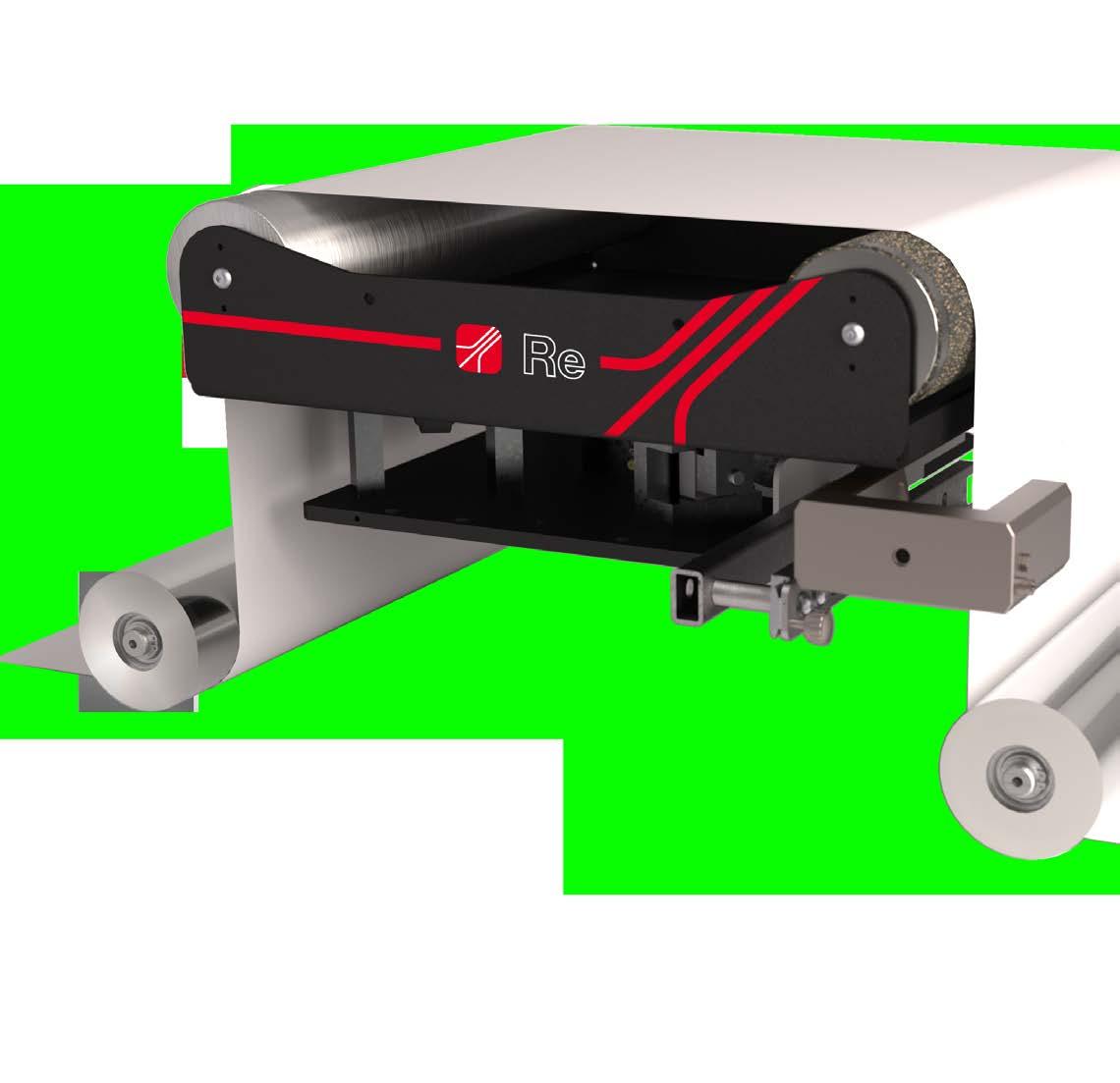
Re web guide systems are designed to solve the problems of edge, centre and line guides for all kinds of material. Thanks to highly innovative technical solutions we have created a range of products that offer our clients many advantages, including:
• high precision stepping motor electrical movement;
• proportional error response for fast and precise checking;
• almost zero maintenance costs;
• extremely low purchase cost;
• easy to use and install system.
I sistemi guidanastro Re sono progettati con l’intento di risolvere le problematiche riguardanti la guida di bordo, di centro e di linea su ogni tipo di materiale. Grazie a soluzioni tecniche innovative, è stato possibile realizzare una gamma di prodotti che offrono numerosi e sostanziali vantaggi:
• movimentazione elettrica con motori passo-passo ad altissima precisione;
• risposta proporzionale all’errore, per un controllo rapido e accurato;
• costi di manutenzione pressoché nulli;
• prezzo estremamente contenuto;
• facilità d’uso e di installazione del sistema.
This catalogue information is correct at date of pubblication, but is subject to change without prior notification, or as required by Re S.p.A. Technical data are also illustrative and for product selection, while designing the application we recommend you to get an opinion from our sales-engineer, in order to select the most suitable size.
I dati del presente catalogo sono ritenuti corretti al momento della pubblicazione, ciò non implica responsabilità da parte della Re S.p.A. per eventuali variazioni intervenute successivamente. È inoltre consigliato, in fase di progettazione dell'applicazione, consultare i nostri tecnici commerciali in modo da selezionare il modello più idoneo.

3 1
1 2 3 2
The sensors register the edge or material line position. The information is sent to the control unit.

I sensori rilevano la posizione del bordo o della linea del materiale. L’informazione viene inviata all’unità di controllo.
The control unit (Resmart, WGL or WLigo) analyses the information and transforms it into a correction signal that is sent to the mechanical device.
L’unità di controllo (Resmart, WGL o WLigo) analizza l’informazione e la trasforma in un segnale di correzione che viene inviato al dispositivo meccanico.
The motorized actuator moves the mechanical device and takes the material back to the right position. Then the mechanical device waits for a new detection reading.
L’attuatore motorizzato muove la struttura e riporta il materiale nella posizione corretta. Il dispositivo meccanico resta in attesa di una nuova rilevazione.
Infinite variations

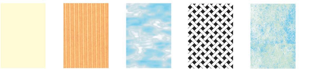


I sistemi guidanastro Re consentono illimitate possibilità di regolazione e guida su un’innumerevole varietà di materiali. Alcuni esempi di rilevamento del bordo o di una linea-guida del


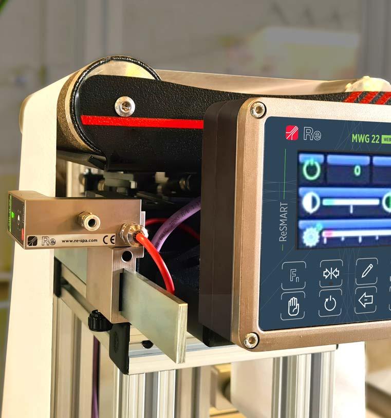
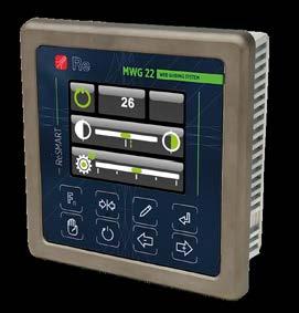
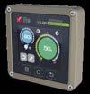
The MWG 10.1 and MWG.22 regulators integrates the control logic and the power driver for stepping motors in a single and very compact case. Thanks to a special algorithm, specifically developed in our R&S department, the system is able to produce a corrective action to restore the material’s position in the desired position.
MWG 10.1 and MWG.22 are equipped with a 2,8” LCD color graphic display, which ensures a rapid and user-friendly human/machine interaction, and some mechanical buttons for an easy calibration and management of the system.
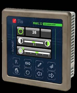
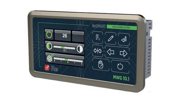
Analogue inputs are suitable for our sensors with analogue output and a CAN interface allow to connect efficaciently with remote keyboard and automatic sensor holders.

MWG.22 can be supplied with fieldbus, ProfiNET or EtherCAT protocol (optional), to be connected and controlled by PLC system.
I regolatori MWG 10.1 e MWG22 integrano logica di controllo e driver di potenza per motori passo-passo in un unico contenitore di dimensioni ridottissime.
Grazie ad un algoritmo di regolazione appositamente studiato internamente alla nostra R&S, il sistema è in grado di produrre l’azione correttiva necessaria a riportare il materiale nella posizione desiderata.
Entrambi dotati di un display grafico a colori LCD da 2,8”, che consente una rapida e intuitiva interfaccia uomo macchina, possiedono inoltre alcuni tasti per una semplice calibrazione e gestione del sistema.
Gli ingressi analogici sono adatti ai nostri sensori con uscita analogica, e un sistema di comunicazione CAN permette di interfacciarsi in maniera efficace con tastiera remota e portasensori motorizzati.
MWG.22 può essere dotato di bus di campo, protocollo ProfiNET o EtherCAT (optional), per interfacciarsi ed essere controllato tramite PLC.
2
* To be used with CAN sensors or remote keypad
**
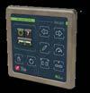
WLigo is the remote keypad to be used with webguiding systems equipped with the Smartmotion system.

Extremely compact in size, it is equipped with a 3,5” resistive touch screen display that allows to smoothly and quickly visualize and regulate all the parameters of each webguide system, and three mechanical buttons for the calibration and management of each device. WLigo can be used to control more than one mechanical device connected in series.
WLigo management is made extremely simple and intuitive by an engaging and user-friendly graphic specifically designed also for those users who have not feeling with the touch screen technology.
The keypad can be provided with cable gland on the back or in the bottom side.
WLigo è la tastiera remota per i sistemi guidanastro Smartmotion.
Di dimensioni estremamente compatte, è dotata di un display touch screen resistivo da 3,5” che permette di visualizzare e modificare tutti i parametri relativi ad ogni guidanastro in modo facile e veloce.

WLigo ha anche tre tasti meccanici per la calibrazione e gestione di ogni strumento e può essere utilizzato per controllare più guidanastri collegati in serie.
L’uso di questo strumento è facile e intuitivo grazie ad una interfaccia grafica di semplice utilizzo pensata anche per coloro che non hanno un buon feeling con le tecnologie touch screen.
La tastiera può essere fornita con pressacavo posto sul retro o sul lato inferiore.
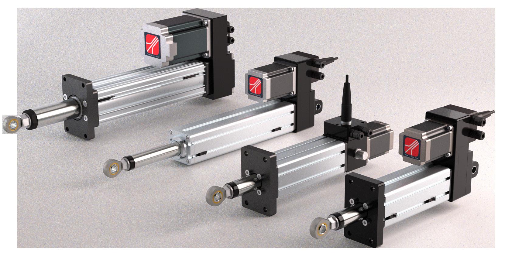
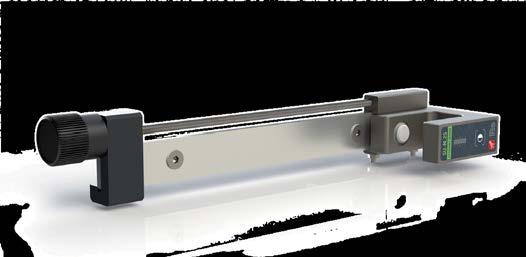
This solution is generally adopted in highly compact machines including an unwind or rewind station. Assembly can be performed with frontal flange, foot or joints.
Axial actuators or with gear box shifting are available to reduce the space required or to increase the thrust force.
The operator can determine the speed with the menu on the control unit (MWG 10.1, MWG.22 or WLigo). The reed electronic limit switch are inserted in the slots of the stem and are easy to access to change the stroke of the actuator.
Utilizzati generalmente su macchine molto compatte, gli attuatori lineari vengono montati su stazioni di svolgimento o avvolgimento. Il montaggio può avvenire tramite flangia frontale, piede o snodi. Nel caso in cui sia necessario ridurre l’ingombro o aumentare la forza di spinta sono disponibili attuatori assiali o con motore rapportato.
La velocità è determinabile dall’operatore attraverso il menu dell’unità di controllo (MWG 10.1, MWG.22 o WLigo).
I finecorsa elettronici reed sono inseriti nelle cave dello stelo e facilmente accessibili per eventuali modifiche della corsa dell’attuatore.

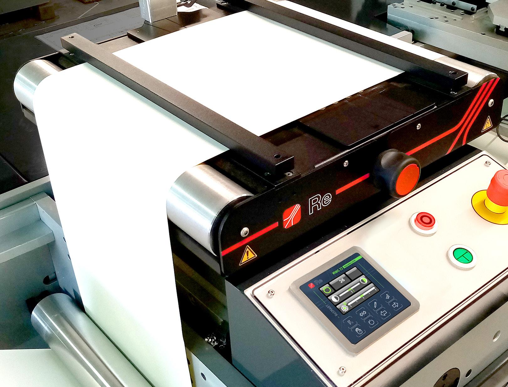
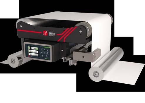
On unwinding phase, the sensor reads the edge or the line of the web to align it correctly before the following process. It is recommended to secure the sensor close to the last unwind guide roller, but still connected to the fixed part of the machine.
During rewinding process, the sensor is applied directly on the rewinder so that it can correct the position of the material in outfeed from the process in real time to produce a reel with a straight profile.
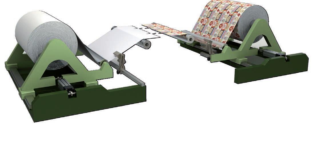
In fase di svolgimento il sensore rileva il bordo o la linea di fede del nastro per allinearlo correttamente prima della successiva fase di lavorazione. È bene fissare il sensore vicino all’ultimo rullo di guida dello svolgitore, ma comunque collegato alla parte fissa della macchina.
In fase di avvolgimento il sensore viene applicato direttamente sull’avvolgitore in modo che possa correggere in tempo reale la posizione del materiale in uscita dal processo ed ottenere una bobina con profilo dritto.
The WG web guides series are the ideal solution for the majority webguide application because the adjustment geometry is fully inside the electro-mechanical system and they can be applied in different positions so that all possible web paths can be used.
There are different models for different machine dimensions and different adjustment requirements:
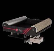
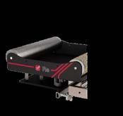
WG.100, WG.251 and WG.255 are the smallest models. They are extremely compact and are usually used in machines that work with narrow webs, such as in the hygiene industry. WG.251-SKB is a special version that integrates the keyboard with the frame with a high protection level (IP54), ideal for dusty environments or in the presence of liquids.
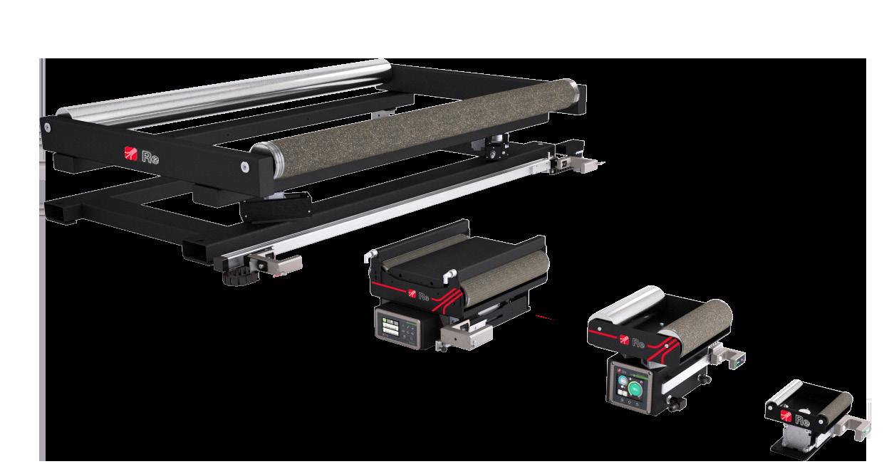
WG.700 and 705 models are usually used in the labels and nonwoven industries. WG.705 is available with the low profile or with the keyboard onboard.
WG.2000 is the largest model of the series usually used on rotogravure, flexographic machines or when the laminates are larger than 800 mm.
I guidanastri della serie WG sono la soluzione ideale per le applicazioni più comuni perché la geometria di regolazione è tutta all’interno del sistema elettromeccanico e possono essere applicati in diverse posizioni permettendo di sfruttare tutti i percorsi possibili del nastro.

Esistono diversi modelli a seconda delle dimensioni della macchina e delle differenti necessità di regolazione:
WG.100, WG.251 e WG.255 sono i modelli più piccoli, estremamente compatti, sono solitamente impiegati in macchine che lavorano nastri stretti, per esempio nell’industria dell’igiene. WG.251-SKB è una versione speciale che integra la tastiera nel telaio e dispone di un elevato grado di protezione (IP54) che lo rende idoneo ad operare in ambienti polverosi o in presenza di liquidi.
I modelli WG.700 e 705 sono solitamente utilizzati nell’industria delle etichette e del nonwoven. Il modello WG.705 è disponibile in versione ribassata o con interfaccia utente integrata nel telaio.
WG.2000 è il modello più grande della serie impiegato su macchine rotocalco, flessografiche o dove i laminati superano una larghezza di 800 mm.
As opposed to frames with physical pivots, in Re web guides the mobile frame rotates around a virtual axis (called “pivot”) which is the ideal rotation axis, allowing for greater adjustment precision. The material elasticity module determines the space needed to infeed and outfeed material from the web guide, which is generally at least ¾ the maximum width of the web.
Guida con carrello imperniato Serie WG
Diversamente dai telai con pivot fisico, nei guidanastri Re il telaio mobile ruota attorno ad un asse virtuale (detto “pivot”) che è l’asse ideale di rotazione, permettendo quindi un maggior grado di precisione nella regolazione. Il modulo di elasticità del materiale determina lo spazio di entrata e di uscita del materiale dal guidanastro, che generalmente deve essere almeno ¾ della larghezza massima del nastro.
higher values are reachable on request valore maggiori sono raggiungibili su richiesta
WG.251 SKB with ReLight system and WGLight control unit, is a completely integrated and optimized web guiding system. It has been designed for some specific industries such as bottling lines and hygiene products production.
Thanks to the experience gained during the years, we developed optimized and ad hoc components for the system in order to simplify production processes and reduce costs.
WGL system guarantee the IP54 protection class and it is equipped with the WGLight keyboard with eight buttons, 1.44” graphic color display, remote controls and alarm.
WG.251 SKB ReLight ensures ease of use and installation
To accurately detect the positioning of the material, as well as rapid response and reliability.
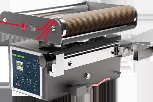
The system can be provided with ultrasonic or infrared sensor; with manual or micrometric positioning system to increase the placement precision.
WG.251 SKB con sistema ReLight e unità di controllo WgLight, è un sistema guidanastro totalmente integrato e ottimizzato, progettato per alcuni settori specifici quali ad esempio quello dell’imbottigliamento o dei prodotti per l’igiene.
Grazie all’esperienza maturata negli anni, siamo riusciti a sviluppare una componentistica ottimizzata e ad hoc per il sistema in modo da semplificare i processi produttivi e abbattere i costi.

Il sistema garantisce un grado di protezione IP54 ed è equipaggiato con la tastiera di controllo WgLight dotata di otto tasti, display grafico a colori da 1.44”, comandi remoti e allarme.
WG.251 SKB ReLight assicura semplicità di utilizzo ed installazione oltre ad elevata precisione, rapidità di risposta e affidabilità.
Per rilevare la posizione del materiale, il sistema guidanastro può essere fornito con sensore ad ultrasuoni o a infrarossi; con possibilità di spostamento manuale o micrometrico per aumentarne la precisione di posizionamento.
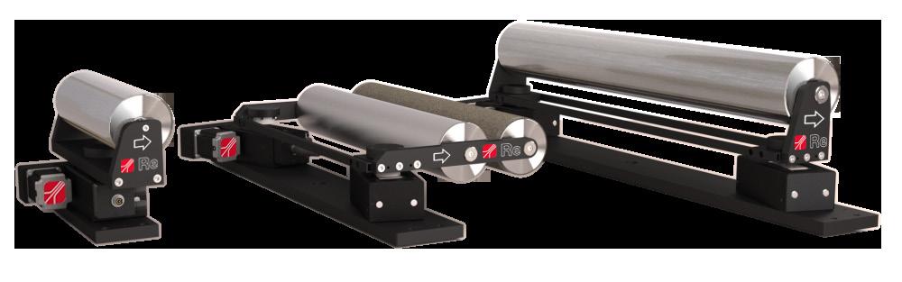
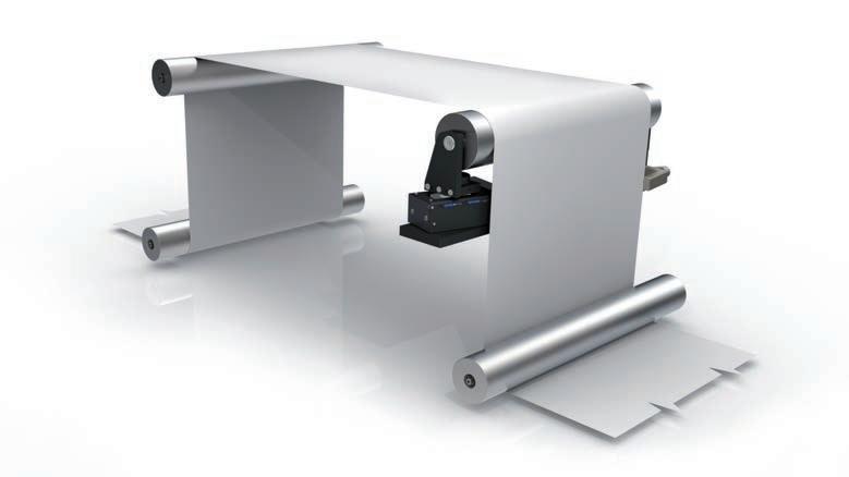
These models are usually used on flexographic machines, in the pre-printing zone or in all those applications where the infeed section is wide (from 2 to 5 times the material width). The WR-S version, with a lower profile, is used when the height needs to be reduced.
The single-roller WR, that use a unique roller of an adequate diameter and fitted with a specific coating to increase the grip, are used in laminating systems. The compact system called MINIROLLER is designed for coating systems and has a single roller smaller than 400 mm applied on a single motorised slide.
Rulli sterzanti Serie WR
Questi modelli vengono generalmente utilizzati su macchine flessografiche, nella zona di prestampa, o in tutte quelle applicazioni dove il percorso in ingresso del materiale è ampio Nel caso in cui sia necessario ridurre gli ingombri in altezza viene utilizzata la versione WR-S che ha un profilo ribassato.
Negli impianti di accoppiamento vengono solitamente installati i WR monorullo di diametro adatto e con rivestimento specifico in modo da incrementarne il grip. Il sistema compatto MINIROLLER, ideato per gli impianti di rivestimento, ha un singolo rullo di dimensioni inferiori a 400 mm applicato su una singola slitta motorizza.

The corrective action of the steering rollers take place on the infeed material plate. The length of the material at infeed must be calculated in relation to its own elasticity, it usually varies between 2 and 5 times the width of the web and this space increases depending on the rigidity of the material.
The material at infeed must be parallel to the web guide’s base plate.
The outfeed section dimension must be included between the maximum material width (M) and its half.
In the event of a single roller, as wide a contact surface as possible must be used and this is why rollers with larger diameters than normal are used.
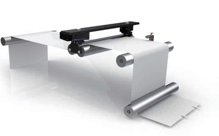
L’azione correttiva dei rulli sterzanti avviene già sul piano d’ingresso del materiale. La lunghezza del tratto in ingresso dovrà essere calcolata in rapporto alla sua elasticità, ma generalmente lo spazio di entrata varia dalle 2 alle 5 volte la larghezza del nastro, e aumenta in funzione della rigidità del nastro. La dimensione del tratto in uscita deve invece essere compresa tra la larghezza massima del materiale (M) e la sua metà. Il materiale in entrata deve essere parallelo alla base di appoggio del guidanastro. Nel caso di rullo singolo è necessaria una superficie di contatto più ampia possibile, per questo è previsto l’uso di rulli con diametri superiori alla norma.
The range of material edge reading sensors, includes ultrasound SU and infrared SIR sensors: the former are able to work with materials such as paper, cardboard and plastic films of any colour or transparent; the latter are ideal on fabrics, soundtransparent materials or with very thick weaves.
The centre guide is always possible by using two sensors at the same time and considering the reading of both edges.
Special versions of both sensors are available:
• ultrasound sensors with centesimal reading,
• ultrasound sensors for noisy environments,

• infrared sensors with pneumatic connection to clean the reading zone from machining residue (AIR version).
La gamma di sensori per la lettura del bordo di materiali comprende i sensori ad ultrasuoni SU e a infrarossi SIR: i primi sono in grado di lavorare con materiali come carta, cartone, film plastici di qualsiasi colore o trasparenti; i secondi sono ideali su tessuti, materiali fonotrasparenti o con trame molto fitte.
La guida di centro è sempre possibile utilizzando due sensori contemporaneamente e considerando la lettura di entrambi i bordi.
Sono disponibili versioni speciali di entrambi i sensori:
• sensori a ultrasuoni con lettura centesimale,
• sensori a ultrasuoni per ambienti rumorosi,
• sensori a infrarossi con attacco pneumatico per la pulizia della zona di lettura dai residui di lavorazione (versione AIR).
transmitter trasmettitore
light luce
lamp lampada
light luce
receiver ricevitore
lamp lampada
receiver ricevitore
infrared/ultrasound waves onde infrarosse/ultrasuoni
transmitter trasmettitore
infrared/ultrasound waves onde infrarosse/ultrasuoni
web
receiver ricevitore web perceptive area area sensibile
light luce
transmitter trasmettitore
receiver ricevitore
transmitter trasmettitore
reflecting material materiale riflettente
web
SIR.70
web
reflecting material materiale riflettente
perceptive area area sensibile
web web
perceptive area area sensibile perceptive area area sensibile
dark surface superficie scura
light luce
light surface superficie chiara
web web
dark surface superficie scura
light luce
dark surface superficie scura
light luce
light surface superficie chiara
perceptive area area sensibile
web
light surface superficie chiara
perceptive area area sensibile
* Different output are available: 0÷10 Vdc o 4÷20 mA
Sono disponibili uscite diverse da quelle standard: 0÷10 Vdc o 4÷20 mA
** For IP54 (protection from dust and splashing of water) request the SKB version
Per IP54 (protezione da polvere e spruzzi di liquidi) richiedere la versione SKB
dark surface superficie scura
light surface superficie chiara
web
Power supply Alimentazione
12÷24 Vdc (Display: 24 Vdc from sensor / da sensore)
Measuring range / Range misurazione
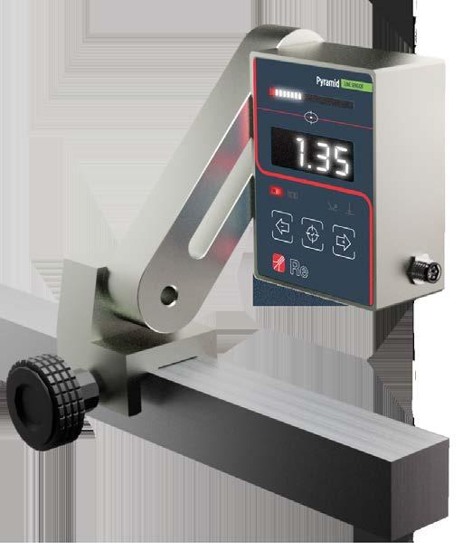
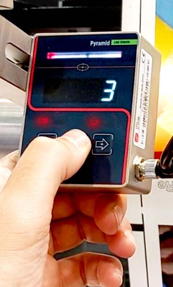
PYRAMID, is an opto-electronic sensor with microcontroller able to reliably and precision detect printed lines, material edges or colored pattern, continuous or interrupted, even with very low contrasts. The sensor’s high precision and reliability ensure that the web stays on the right path, guaranteeing dependable production and reduced waste.
PYRAMID is equipped with three buttons for the calibration and for managing the sensor’s advanced functions. It is equipped with an intuitive display with four digits and a barraled to indicate some parameters of the sensor and the positioning of the line/edge. Some other LED indicators give informations about the operating status of the sensor.
A led indicator allows you to easily view the reading area; moreover, the sensor is able to automatically select the best contrast light colour (blu, red, green or white; or UV for for the models that provide it) to obtain the best contrast between the background and the line or edge.
Edge reading / bettura bordo
Pattern reading / lettura pattern ~20 mm ~12 mm
Response time
Tempo di risposta 1 ms
Analog output
Uscita analogica 0÷5 V / 0÷10 V (optional)
Distance PYRAMID-material
Distanza PYRAMID-materiale 50 mm
CCD Sensor
Sensore CCD 1 x 512 pixel
Cable length
Lunghezza cavo < 30 m
Working temperature
Temperatura di esercizio 0÷50°C
Protection class Classe di protezione IP20
PYRAMID, è un sensore opto-elettronico a microcontrollore in grado di rilevare con affidabilità e precisione linee stampate, bordi di materiali o pattern colorati, continui o interrotti anche con contrasti molto bassi. Grazie alla sua precisione e affidabilità il vostro nastro sarà sempre posizionato in modo corretto, garantendovi un processo produttivo con minimi scarti.
PYRAMID è dotato di tre tasti per la calibrazione e per la gestione delle funzioni avanzate del sensore.
E’ equipaggiato con un display intuitivo a quattro digit ed un barraled, utili per indicare alcuni parametri del sensore ed il posizionamento della linea/bordo.
Altri LED indicatori sono presenti per fornire ulteriori informazioni sullo stato di funzionamento del sensore. Un indicatore led permette di visualizzare con facilità l’area di lettura; inoltre, il sensore è in grado di selezionare automaticamente il colore dell’illuminazione di contrasto (luce blu, rossa, verde o bianca; o UV per i modelli che lo prevedono) in modo da ottenere il massimo contrasto tra sfondo e linea o bordo.

Re’s line sensor PTS25 has been designed to identify the position of continuos or interrupted lines, printed edges, web edges and patterns of any kind on a moving web even at the highest web speeds. The sensor’s high precision and reliability to identify color differences ensure that the web stays on the right path, to guarantee a correct productive process and to reduce wastes.
The PTS25 has been designed to optimize the operator experience by using a simple and user-friendly interface, text messages and even assisted calibration.
The PTS25 is equipped with a 5” color touch screen display that ensures reliable reproduction of the real image. Two high-power LED lights produce true white light to ensure the best performance even in bad lighting conditions. The sensor is provided with a viewing area of 25x16 mm and with digital and analog inputs and outputs.
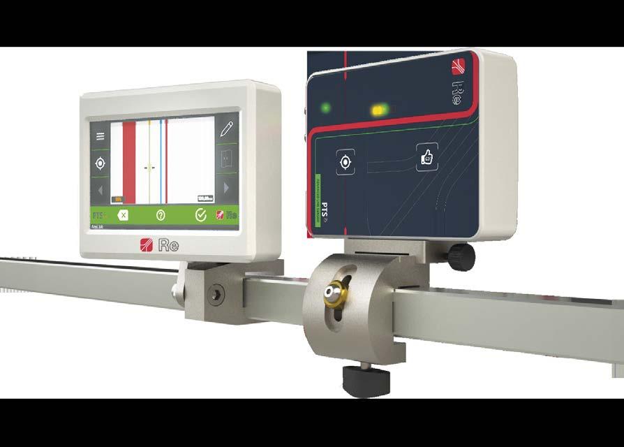
Il sensore di linea PTS25 è in grado di individuare ed inseguire la posizione di una linea continua o interrotta, bordi stampati e pattern di un qualsiasi materiale in movimento anche alle più elevate velocità. Grazie alla sua estrema precisione e affidabilità nel riconoscere variazioni di colore, il nastro in movimento sarà sempre posizionato perfettamente per garantire un processo produttivo corretto e minimizzare gli scarti. PTS25 è stato progettato per offrire all’operatore un’esperienza uomo-macchina unica grazie ad un’interfaccia estremamente intuitiva, a messaggi testuali e, soprattutto, alla calibrazione assistita.
PTS25 è equipaggiato con un display 5” touch screen a colori che assicura la riproduzione fedele dell’immagine sottostante e dei suoi colori e di due illuminatori LED a luce bianca ad alta potenza per garantire le performance in qualsiasi condizione di luce. È dotato di un campo visivo di 25x16 mm e uscite ed ingressi digitali e analogici.
PTS25 is provided with an assisted calibration system; during this process the PTS25 faithfully reproduces the whole real image, not only the line, and automatically recommends lines or patterns to follow, showing the reliability percentage of each one.
PTS25 è dotato di un sistema di calibrazione assistita durante il quale riproduce fedelmente l’intera immagine sottostante, non solo la linea, e suggerisce in modo automatico le linee o pattern da seguire mostrandone per ognuna la percentuale di affidabilità.
CAMPO VISIVO 25x16 mm
The field of view of 25x16 mm allows the PTS25 sensor to frame a great portion of the material in order to find the best line, image or pattern to follow. The acquired image is shown on the display with a 3x zoom.
Il campo visivo da 25x16 mm permette al sensore PTS25 di inquadrare una porzione di materiale utile a trovare la miglior linea, immagine o pattern da seguire. L’immagine acquisita è mostrata sul display con uno zoom 3x.
60 mm DAL MATERIALE
Particular attention has been paid to the mechanical installation of the sensor. Thanks to a proper bracket and the ability to locate the sensor up to 60 mm from the web, without losing focus on the image, PTS25 doesn’t have to be (re)moved during web positioning.
Grande attenzione è stata posta sull’installazione meccanica del sensore: grazie ad una staffa snodata e alla possibilità di posizionarlo a 60 mm dal materiale senza perdere la messa a fuoco dell’immagine, il sensore PTS25 agevola l’incorsamento del materiale.
Thanks to a speed regulation of 1 kHz, the sensor is able to track and regulate with high reliability any type of moving material even at the highest speeds.
Grazie ad una velocità di regolazione di 1 kHz, il sensore è in grado di inseguire e regolare con elevata affidabilità qualsiasi tipo di materiale in movimento anche alle più elevate velocità.
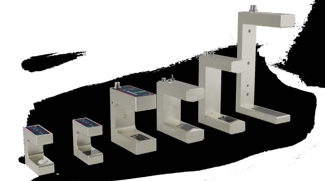
The micrometric adjustment sensor holder is used in applications where the operator needs to position the sensor precisely and without using the remote control set-point function.
All the sensors can be installed on motorised sensor holders with integrated encoder. The automatic sensor holders are also equipped with stepping motors that guarantee its related advantages, such as precision and rapid movement.
These solutions are usually adopted on systems where the operator has to frequently change the position of the sensor or where access to the sensors is too difficult to consider a repeated manual intervention.
Il portasensore micrometrico viene utilizzato in applicazioni in cui l’operatore necessita il posizionamento accurato del sensore evitando l’uso della funzione set-point remoto.

Tutti i sensori possono essere installati su portasensori motorizzati con encoder integrato. Anche i portasensori automatici sono dotati di un motore passo-passo beneficiando dei relativi vantaggi in termini di precisione e rapidità di movimento.
Queste soluzioni sono solitamente usate su macchine in cui l’operatore deve modificare frequentemente la posizione del sensore, o quando l’accesso ai sensori è troppo difficoltoso per considerare un intervento manuale reiterato.


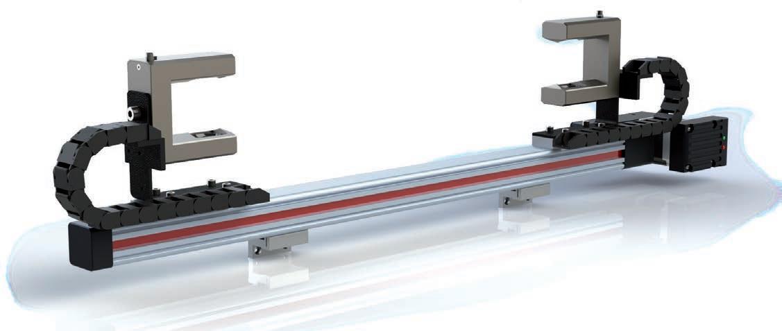
Automatic sensor holders are the ideal application for all joining machines using the so-called “chase” system. The automatic sensor holder with the MASTER sensor is used for reading the reference edge of the material, whereas the second sensor holder with its SLAVE sensor reads the edge of the material to be joined. The SLAVE webguide moves the exiting material to join it precisely. The two sensor holders are monitored constantly and regulated on the basis of the material position and the parameters set by the operator on the MWG 10.1 or MWG.22 remote control unit.
I portasensori automatici sono l’applicazione ideale per tutte le macchine accoppiatrici con sistema ad inseguimento. Il portasensore automatico con un sensore MASTER è utilizzato per la lettura del bordo di riferimento del materiale, il secondo portasensore con sensore SLAVE legge invece il bordo del materiale da accoppiare. Il guidanastro SLAVE muove il materiale per accoppiarlo in modo preciso al materiale in uscita dal MASTER. I due portasensori sono costantemente monitorati e regolati in funzione dello spostamento del materiale e dei parametri impostati dall’operatore, attraverso MWG 10.1 o MWG.22.
The WO software, besides the webguide classic mode, includes the oscillator mode: the webguide performs a series of continuous settable and speed oscillations, so it can produce a uniform reel when the material used has an uneven surface, as in “CAST” plants where the material is usually thicker at the edges.
Il software WO, oltre alla classica modalità guidanastro prevede la modalità oscillatore: il guidanastro compie delle oscillazioni continue di ampiezza e velocità impostabili, producendo una bobina uniforme anche in quei casi in cui il materiale non è omogeneo, per esempio negli impianti “CAST” dove il materiale ha uno spessore solitamente maggiore sui bordi.
The system reads the material width using two SU/SIR sensors on an automatic sensor holder with encoder integrated. The information is shown in mm directly on the MWG 10.1 or MWG.22 display. This function is particularly useful on plants for extruding plastic as it can provide feedback regarding the extruder checking system.
ll sistema è in grado di leggere la larghezza del materiale utilizzando due sensori SU/SIR su barra motorizzata automatica con encoder integrato. Il dato è visualizzato in mm direttamente sul display MWG 10.1 o MWG.22; questa funzione è particolarmente utile negli impianti di estrusione della plastica perché permette un’eventuale retroazione sull’estrusore stesso.
CONFIGURATION / CONFIGURAZIONE
CONTROL UNIT / UNITÀ DI CONTROLLO
Optional
MWG 10.1 Standard WO (oscillator)
MWG.22 Standard
WEBGUIDE / GUIDANASTRO
Remote display Tastiera remota
Power supply 5 A Alimentatore 5 A
WLigo Standard
Optional RCU (Remote contact unit) Power supply 5 A Alimentatore 5 A
See table at page 5 / vedi tabella a pagina 5
AT WG
WG .251 SKB + ReLight WG .251 SKB + WLigo
Optional Roller coating Rivestimento rullo
EDGE SENSORS SENSORI DI BORDO
Cork / Sughero Tape rubber / Tela siliconata Other / Altro
LINE SENSORS SENSORI DI LINEA
Ultrasonic / Ultrasuoni Optical / Ottici Infrared / Infrarossi
SU.5-B50 SU.5-B100 SU.FAST SU.FAST MLO SU.M-25
SENSOR HOLDERS / PORTASENSORI
Single micrometric Micrometrico singolo Manual Manuale
PYRAMID PTS25
Single 1S/1M (master) Singolo 1S/1M (master)
Single 1S/1M (slave) Singolo 1S/1M (slave)
Exiting roller Rullo in uscita Both / Entrambi Optional Power supply / Alimentatore 5 A
Double micrometric Micrometrico doppio
Only for MWG 10.1 / solo per MWG 10.1
Double 2S/1M (blow film extrusion)
Doppio 2S/1M (estrusori)