12 minute read
Other Simple CAB for Yard or other motors
A Motor Speed Control
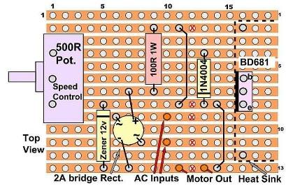
This is a simple motor control circuit. It has good starting characteristics and it will run at a slow speed. It could be used for a loco motor, turntable drive motor, accessory equipment such as cranes, winches, etc. Use it for a single direction motor or with a change over switch, bi- direction control. It can be powered by an AC plugpack (Wall Wart) of 14 to 16 volts AC or a transformer. With the pulsing DC developed from the AC input it has good start and slow running characteristics and it is gentle enough to be used with all types of motors. There is some feed-back from the motor that will increase the drive voltage if a heavier load is encountered. The power source selected should have enough voltage and amperage to match the motor. The circuit components can be altered to suit the motor. It is not a precise controller and the speed will vary slightly as the transistor heats up, so a heat sink is essential. With the speed control at minimum (to the right hand side on the diagram) there is still a trickle of voltage being supplied to the motor which, if it is in a loco, will 'tickle' a block detector or if driving a turntable, it can be used to bias the motor and hold it onto the stop at the selected track position. The transistor used is a Darlington type which gives a high power output for low base drive current. As it has to absorb the surplus voltage not used by the motor it can get warm and a heatsink is needed. The bridge rectifier gives a full wave rectification and the voltage out of it goes from zero volts to about 19 volts and back to zero at twice the -
Advertisement

mains frequency (120 times per second in the USA) This gives an average voltage of about 16 volts. The zener diode limits this to a zero to 12 volt pulsing wave. With the potentiometer 'off' there is a small current through the resistors and diode to the motor. Not enough to run it, but it could be used to hold the motor against a stop. The potentiometer resistance can be changed to adjust this bias power, 500 ohms gives about 1 volt, 100 ohms about 3 volts. When the speed control is moved off 'Low' the transistor starts conducting and it supplies a higher voltage to the motor and starts it. The voltage to the motor can go as high as the zener diode regulated voltage value.
Components
One resistor of 100 ohms at 1 watt,
Potentiometer with PCB mounting of 500 ohms, ᄑ to 1 watt,
a 2 to 4 amp bridge rectifier, W06
a 12 volt 1 watt zener diode (depending on the motor running voltage needed),
a 1 amp diode type 1N4004,
Darlington transistor BD681 for motors to 1.5 amp and TIP141 for up to 3 amp power.
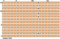
A Heat sink to suit the transistor that has a screw or solder mount to secure it to the 18 by 13 hole veroboard (resize if necessary to suit the heatsink)
Chapter 6a-2 Page 37

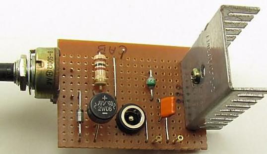
The PCB has a socket for the plug-pack lead.
Servo Driver
Trains are not the only things that move in the real life scene. How does your model look?, great scenes but nothing moves? That メ s not too hard to remedy.
Radio Control sets use a specialized servo that gives a 180 degree movement on command of a control pulse. It can easily be linked to things we want to move on the layout, road crossing arms, turnout motors, loco shed doors, turn tables to mention a few. A servo is a geared motor whose output wheel or arm can be accurately positioned by a command pulse. The pulse is sent at regular intervals and the servo will hold its rotation position. The pulse width range is 1 millisecond to 2 milliseconds at about 16 to 20 milliseconds interval. The motors are small and due to the reduction gearing have a good torque. The output wheel or shaft can travel about 200 degrees. This circuit will generate 2 control pulses depending on a switch position. The two control pulse values can be adjusted to set the rotation required. Servo movement speed depends on the servo but usually is fairly fast. Servo mechanisms are varied, at present there is a range in price from $6 to $20. Quality of movement varies, cheaper ones will have less accurate positioning and perhaps some overshoot. I have not tested all of them but most will be suitable.
You don't need the high output power type unless you plan to lift/move a heavy weight and then the power required may exceed the current capabilities of the circuit. If you know anyone who is into competition RC Aircraft flying have a talk to them about second hand servos as
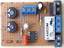
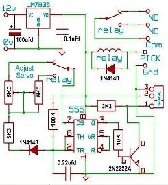
most will change servos yearly to avoid flight failures. There are even servos with a linear movement instead of the usual rotary type. The only minus with the motors is that they run on 5/6 volts so a small regulator has to be included in the circuit if you plan to run on a 9 to 15 volt supply. The circuit is controlled by a ground level. This can be from a toggle switch or a grounded input from another circuit. This picks the relay to change the discharge current path for the timing capacitor. The charge time (pulse off time) is fixed at about 16 to 20 milliseconds which is standard for the servos. The 5 volt power for the servo comes from an IC 5 volt regulator which needs a 9 to 15 volt input. The timer output voltage is the opposite to that required by the servo so a transistor is used to invert the pulse.
Options for the circuit.
Turning the trim potentiometer clockwise increases the pulse length. The pulse is variable from 0.9 milliseconds to 2.5 ms. Although these are the extreme limits of the servo movement and it may chatter the motor, back off a little if this occurs as it can soon overheat the regulator. For the normal range of 1 ms to 2 ms the servo will rotate about 180 degrees. Often the 2 ms can be stretched toward 2.5 ms to get slightly more rotation. 1. The relay can be left out, solder across cuts at 6/21, 8/21, 10/21 wire a change over switch to NO-Com-NC terminals if you are reasonably close to the PCB position. The turnouts in a yard might be one use for this option. 2. One of the adjusting Potentiometers could be replaced with a resistor (4K3 value) if you do not need to adjust one end of the movement. 3. Leave out the relay, connect the Common and normally closed contacts together (8/19, 10/19) and use a remote 5K0 potentiometer for P1, located off the PCB to give a continuously variable pulse and servo rotation. 4. A second servo PCB without the regulator could use the 5 volts and ground from this one (row 4 and 5 have 5v and 0v on them) and link these to the second PCB.
The second set of change over relay contacts is available for crossing lights, lamps, signals, sounds etc..
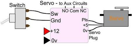
This is a simple circuit. More complex ones can be found to let you also control the speed that the servo moves between the two
Construction:
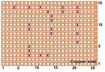
Cut the Strip board to size, 25 holes along the copper row and 15 rows high. A bit more if you want to include mounting screws but mask off the extra holes so you are not confused when marking for the cuts and installing links. Clean and burnish the copper strips so they solder easily. Now on the copper side mark the positions of the holes to be cut. The diagram shows the view on the copper side. Double check the marks and then twist a #32 drill bit in the hole so the copper strip is cut right through. Examine with magnifier or meter them to ensure they are fully cut. Turn the board over and install the vertical link wires, use a thin single strand covered wire, I found kynar covered wire-wrap wire good for this. As you insert and solder the wires double check the position against the cut holes to avoid mistakes. There are 15 link wires and 3 positions where a wire has to be soldered across the copper strips, shown RED on the diagram at row 3/12, row 13/19 and 13/22. When soldering, put the bit against the copper and the component lead and after one second touch the solder to the joint. The solder should spread along the copper and wick up the lead. Pull the bit up the lead as you remove the soldering iron to avoid spill onto adjacent strips. Now the diodes (check position) and resistors can be soldered in. Then the LM555 and trim potentiometers (Pot) Lastly all the larger components. The miniature type of relay used has two possible contact orientations, check the side of it for a diagram or use a meter to verify which pin is which.
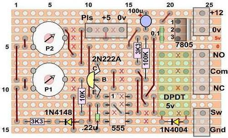
They may have the common 1/4 turn and apply power at the center of the three pins again. If there is no (as in the diagram) or at the movement then you will have first of the three. You will to find the reason by double have to change the wiring as checking everything again. At in the smaller vero-2 diagram this stage get expert help. if it is the second type. Installation: The installation To finish do a visual check required will vary but ensure against the vero diagram, turn the Servo is firmly secured, it the board over and run a should not overdrive the hobby knife blade along the mechanism's end stops as rows between the copper this will rock the servo strips to make sure there are mounting and may destroy it. no solder bridges between Note that cheaper servos them and examine closely may have some overdrive with a magnifier to ensure all before they settle to the joints are soldered. correct position. Using the The servo will need a rubber grommets on the matching socket to connect it servo mounts will allow a little to the terminals on the board. bit of flexibility in the Connect a switch or use a movement, as done in aircraft bridging wire for the 'Sw - mountings. Or you could use Gnd' terminals while testing. a spring loaded link that will Move the Pots to about center allow overshooting a fixed position and apply power. The stop. Adjust the Pots until you servo should move a little or get the required movement. buzz. If not remove power, Start with the Pots about change the Pot position about center and adjust from there. Which one and the position they control is up to you.
Servo for Radio Control
Wires to the main board
RC servos are an electric motor mechanically linked to a potentiometer. Signal pulses sent to the servo are decoded into a voltage by the electronics in the servo. The servo motor potentiometer produces a voltage proportional to its rotated position. If this is different to the decoded voltage from the input pulse then the motor is supplied with power to correct the position. The servo interface is three wires: ground (black), power (red) and control (brown/white). The servo expects a pulse every 16 to 20 ms or it may lose position. A servo pulse of 1.5 ms width sets the servo to its "center" position. In general the servo's angular rotation will be somewhere in the range of 180° to 210° for a minimum pulse of 1.0 ms and maximum of 2.0 ms. Internally the servo has two parts, the gears and potentiometer above and electronics below. The electronics are miniature components and are not repairable. By removing the limit on the drive gear and the drive to the potentiometer, then locking the potentiometer in its central position the servo will become a variable speed motor, depending on the pulse width. Rotation direction depends on the pulse being above or below the central position.
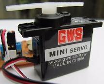
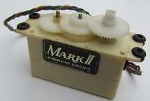
This is a popular make of medium sized servo. It is supplied with a variety of ‘wheels’ and ‘horns’ This one has a long arm fitted which will give a large 180 degree rotary movement. There are four mounting holes on the top flange, and the rubber grommets, screws and washers for mounting are supplied. The lower picture shows the gear train of an older make of servo. The gears are covered by the case and only the square shaft sticks out. The wheel or arm screws onto that. The final drive gear can be metal for better wear. The potentiometer is directly below the drive gear and driven by it so there is no back lash
Components:
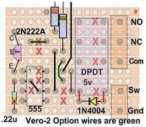
Resistors, all 1/6 or 1/4 watt. 2 of 3300 Ohms, [3K3] 2 of 10,000 Ohms [10K] 2 of 100,000 Ohms, [100K] Capacitors, 0.1ufd, 0.22ufd plastic, electrolytic at 16 volts, 1 of 100ufd Diodes, one each of 1N4148 and 1N4004 Transistor 2N2222A, 2N3904, BC547 or any utility NPN type Timer IC LM555, NE555, 7555 all are suitable Relay Small PCB type DPDT at 5 volts. See note on which type. Regulator LM7805 or equivalent. Potentiometer, PCB mount, 2 of 5,000 Ohms, [5K0] Screw PCB mount terminal strips, 2 of 2 way and 2 of 3 way, or as required. Matching servo cable socket. Stripboard 25 holes by 15 rows.
Resistor Color Codes
Symbol Value No. 3K3 3,300 Ohms 2 10K 10,000 Ohms 1 100K 100,000 Ohms 1 3 band plus tolerance. orange-orange-red brown-black-orange brown-black-yellow

4 band plus tolerance band. orange-orange-black-brown brown-black-black-red brown-black-black-orange


