
TABLE
OF CONTENTS
I. PROFESSIONAL
GEORGE WHITE STADIUM GARY W. HARRIS CANADA GAMES CENTER 80 WEST BROADWAY 1558 TREMONT 1395 WASHINGTON II. ACADEMIC CAMBRIDGE COMMUNITY RECREATION CENTER 05 04 10 22 29 32 37 36 BERKLEY BEAR FIELD HOUSE 16 3
STANTEC ARCHITECTURE
MAY 2014 - JUNE 2020 MAY 2022 - PRESENT
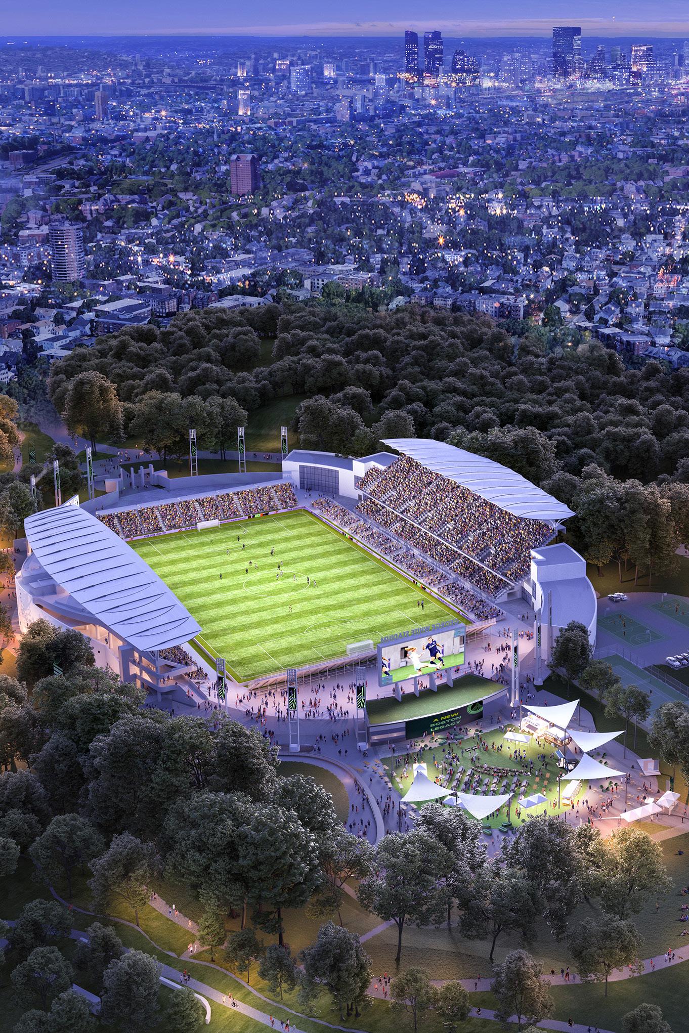
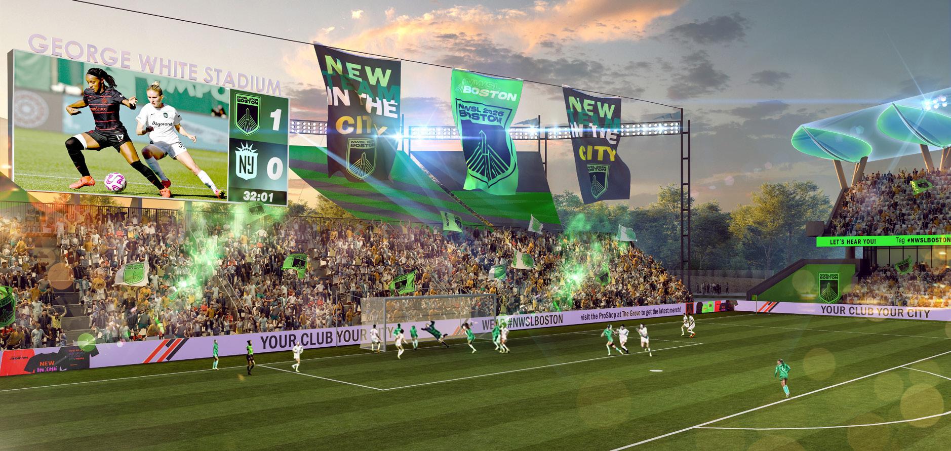
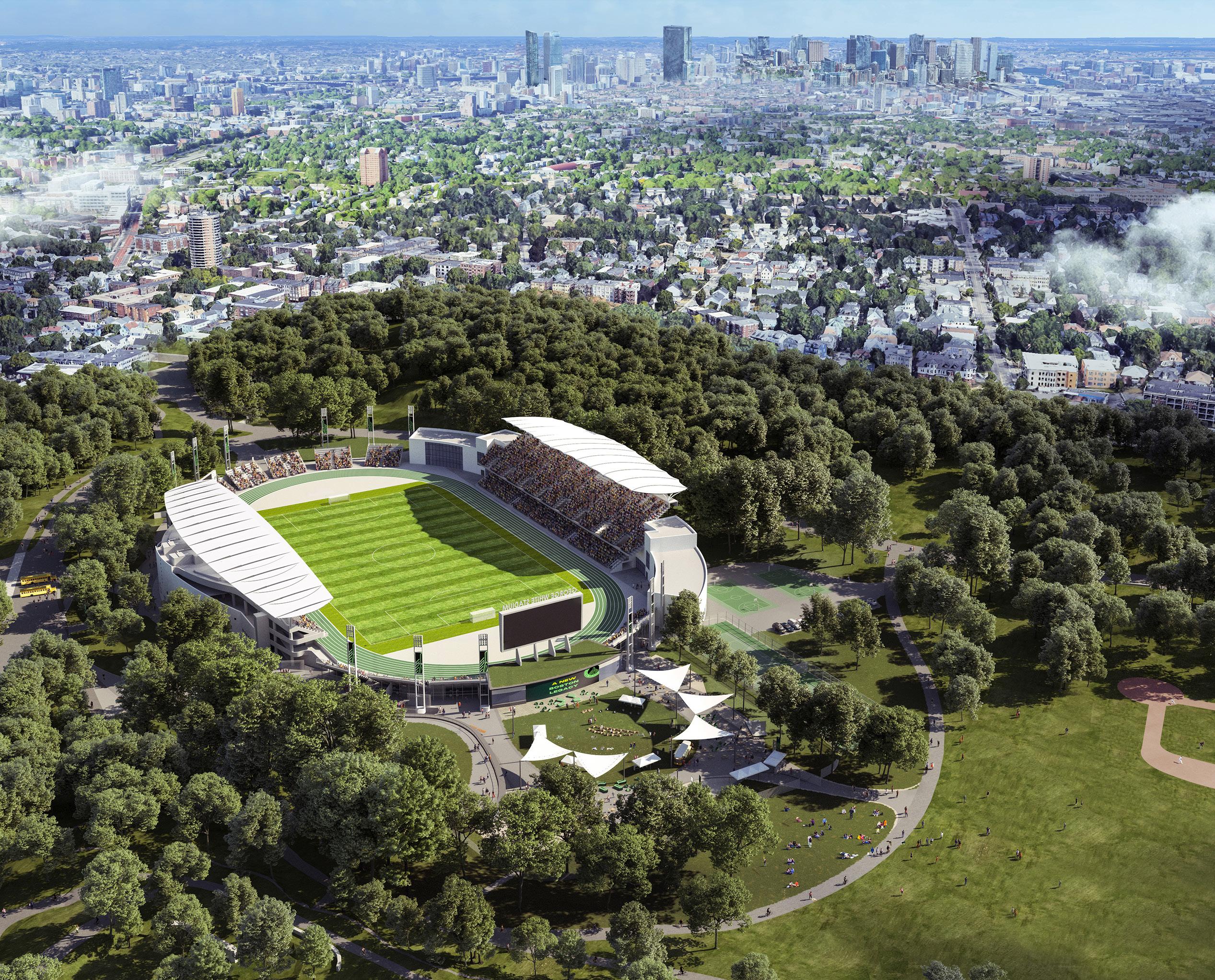
The City of Boston is building a new stadium to host their new expansion franchise of the National Women’s Soccer League (NWSL), and our team at Stantec was selected to be the Design Architect. Our team intends to use selective demolition to reimagine the existing George White Stadium, giving precedence to the historic structures and plantings currently within the beloved Frederick Law Olmsted designed park. As joint partners, our design accomodates for NWSL professional standards, while continuing to host Boston Public School sporting events. White Stadium and its adjacent event space, The Grove, project to become vibrant cultural and community resources once again.
WHITE STADIUM
Firm: Stantec Architecture
Client: Boston Unity Soccer Partners
Type of Project: Stadium
Location: Boston, MA, USA
Role: Designer, BIM Manager, MEPFP Coordination,
Technical Skills: Working on the White Stadium project has been a mad-dash of design presentations, public processes, utility coordination, and political discourse, where my role varies throughout the day. Where my responsibilities fell most consistently, was on MEPFP coordination of our design proposal, as well as site improvements. In this role, I led coordination calls with our consultant teams ensuring that all of our engineers had the most up to date information on a fast-paced project frequently going through design changes and reviews.
5
The existing structure currently at Franklin Park is a 80-year-old stadium featuring two grandstands (approx. 10,000 seats total) and a playing field. In the 1970’s, a proposal was made to enlarge the stadium to 50,000 seats to accomodate a potential new home for the New England Patriots, however the idea was shelved. 50 years later, what is left is a deteriorating stadium that has been neglected for decades.
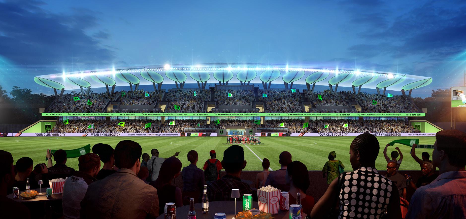
The new design proposal will add additional seats to bring the capacity to meet the league minimum, while also adding concessions and team facilities that will bring this once prominent stadium into the 21st Century.
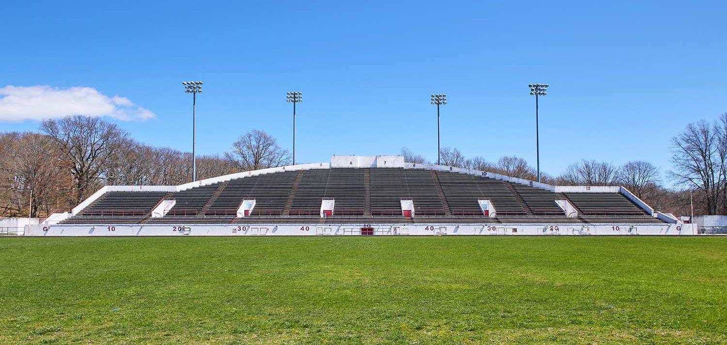
 White Stadium West Grandstand Existing Conditions
PROFESSIONAL PRACTICE 6
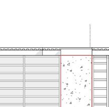
White Stadium West Grandstand Proposed Design
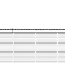
First Floor Plan - Existing “Clamshell” wall depicted with dark grey poche
L UP UP A B D F G I K L 2 1 3 4 X2 5 AA E C H J HOME TEAM LOUNGE MGR OFFICE MENS WOMENS ENTRY VESTIBULE VISITING TEAM LOUNGE CONTROL RM 1 SEATING STORAGE WOMENS MENS F&B OFFICE F&B STAFF LOCKERS SHADING AUDIO CONTROL RM CORRIDOR TOC SEATING STORAGE TUNNEL CLUB STORAGE MAIN ELEC RM GROUNDSKEEPING WATER FIRE SERVICE RM STAIR D TRASH ROOM FIELD LEVEL RESTROOMS FIELD LEVEL RESTROOMS SECURITY HOME LOCKER ROOM BAR BEVERAGE SUPPORT MEDIA INTERVIEW RM VISITOR LOCKER ROOM MAIN KITCHEN TRAINING ROOM LOADING COMMISSARY FOOD STORAGE GAME OFFICIALS LOCKERS TUNNEL CLUB LOUNGE
WHITE STADIUM 7
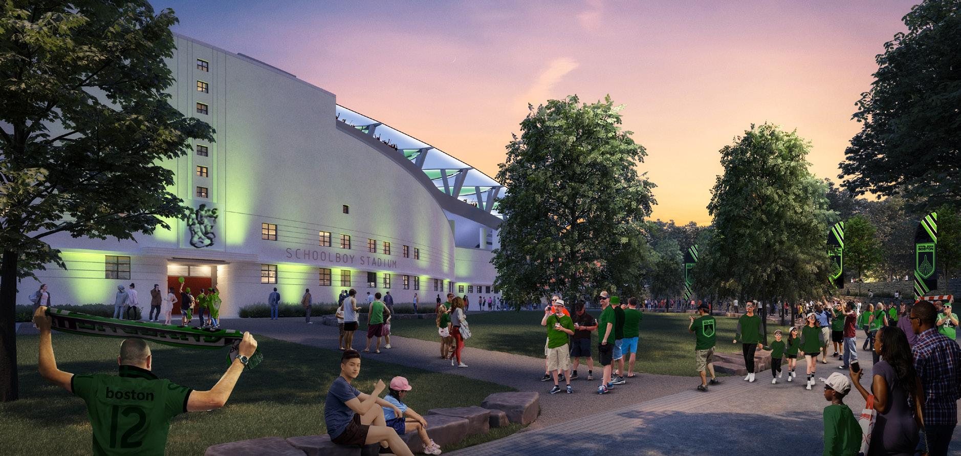
The design intends to maintain the existing “clamshell” wall, in order to preserve the history already rooted in the park. Both end zones will also house additional telescopic seating that can be accomodated for both professional soccer matches, and Boston Public Schools Track & Field events.
PROFESSIONAL PRACTICE 8
9
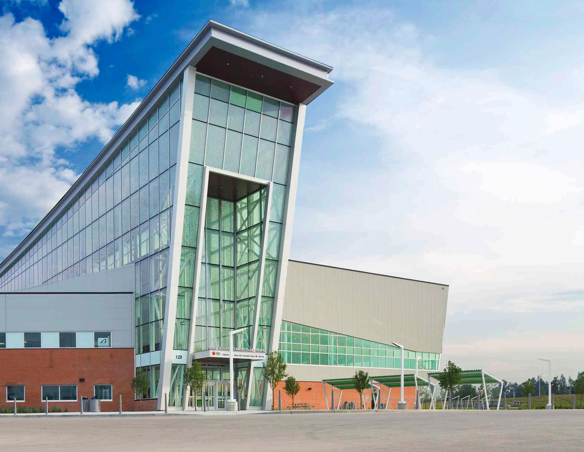
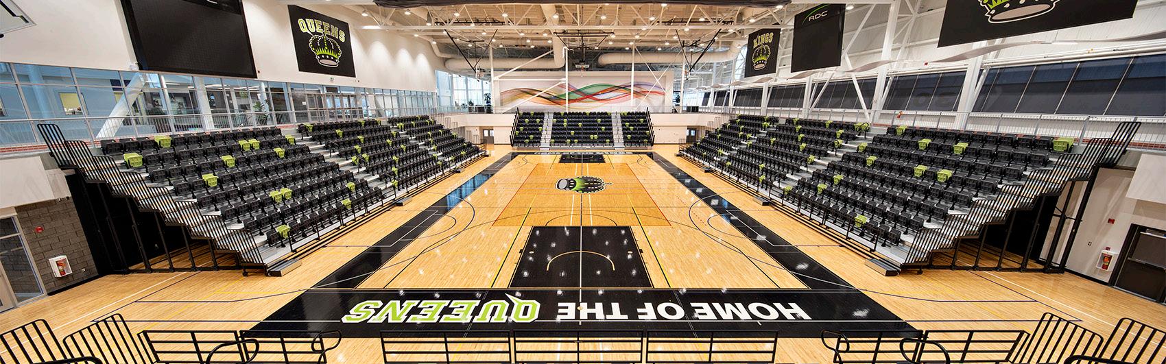
The Gary W. Harris Canada Games Center was a successful design/build project that features an ice rink that can be converted from an Olympic sized sheet to a hybrid that is also designed to be accessible for Sled Hockey, a double gymnasium with seating for 1,200, a fitness center, the Health Sciences campus, and much more. The Center has hosted a plethora of events including the 2019 Canada Winter Games. Prominently visible off the Queen Elizabeth II Highway in Alberta, the Canada Games Center has provided the Red Deer community with a much needed gateway to both physical and mental wellness.
GARY W. HARRIS CANADA GAMES CENTER
Firm: Stantec Architecture
Client: Red Deer College
Type of Project: Sports & Recreation, Academic
Location: Red Deer, AB, Canada
Role: Designer/Marketing
Technical Skills: Working on the proposal for this project was my entire focus for four months as our team strove to win this project. My major contributions were in developing graphics for the proposal, highlighting our deliberate design decisions stemming from the roots of health and wellness.

10
11
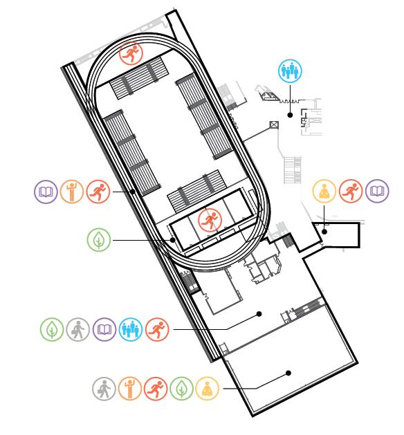
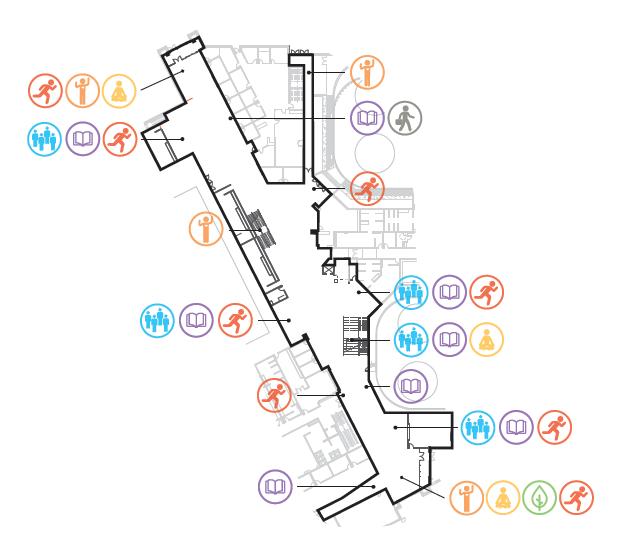
2.1 Defining Space
One of our many spatial planning exercises, the client had asked us to conceptually define each individual space in the project according to a series of components:
Supplementary to the spatial colouring diagrams, the client had asked us to conceptually define each individual space according to a series of components:
Second Floor Fitness Concept Plan Main Floor Great Hall Concept Plan
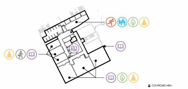
Second Floor Fitness Concept Plan
Emotional
Emotional
Spiritual
Spiritual
Environmental
Environmental
Occupational
Occupational
Physical
Physical
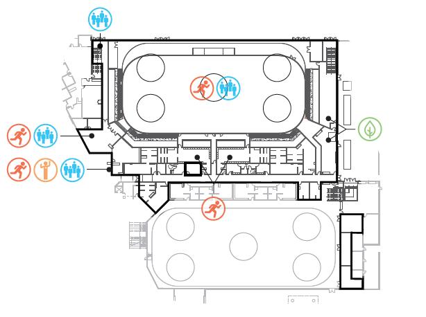
Floor Great Hall Concept Plan Main Floor Olympic Arena Concept Plan
Floor Kinesiology Concept Plan
Main Floor Olympic Arena Concept Plan Main Floor Kinesiology Concept Plan
Career & Academic
Career & Academic
Social & Inclusive
Social & Inclusive
Myself, along with another member of the project team, created these icons using Adobe Illustrator. We then placed them to spaces throughout the floor plans wherever we saw fit.
Being able to identify and associate each space with an emotional connection allowed us to communicate with our client the importance and intricacies of design in each individual space within the design.
Major Contributors: Janine Law, Ross McKinnon
Main
Main
PROFESSIONAL PRACTICE
12
GARY W. HARRIS CANADA GAMES CENTER
Career & Academic Connection to Community Pedestrian connection Future internal link Connection to Waskasoo Creek Environmental Social First Floor Informal Fitness Programming Cardio Outdoor Fitness Stretching Dryland Training Physical I’ve had projects From to enhance my career one Red Wellness, and entire contribution representation of showing behind each Career & Academic Connection Social Connection Physical Connection Environmental Connection
13
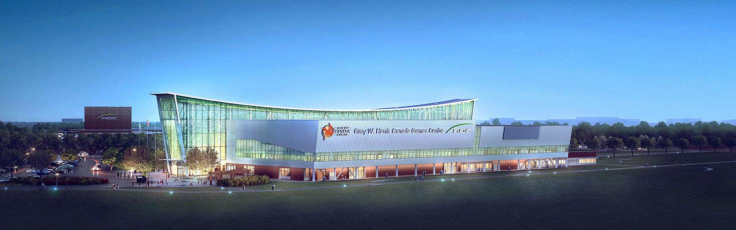
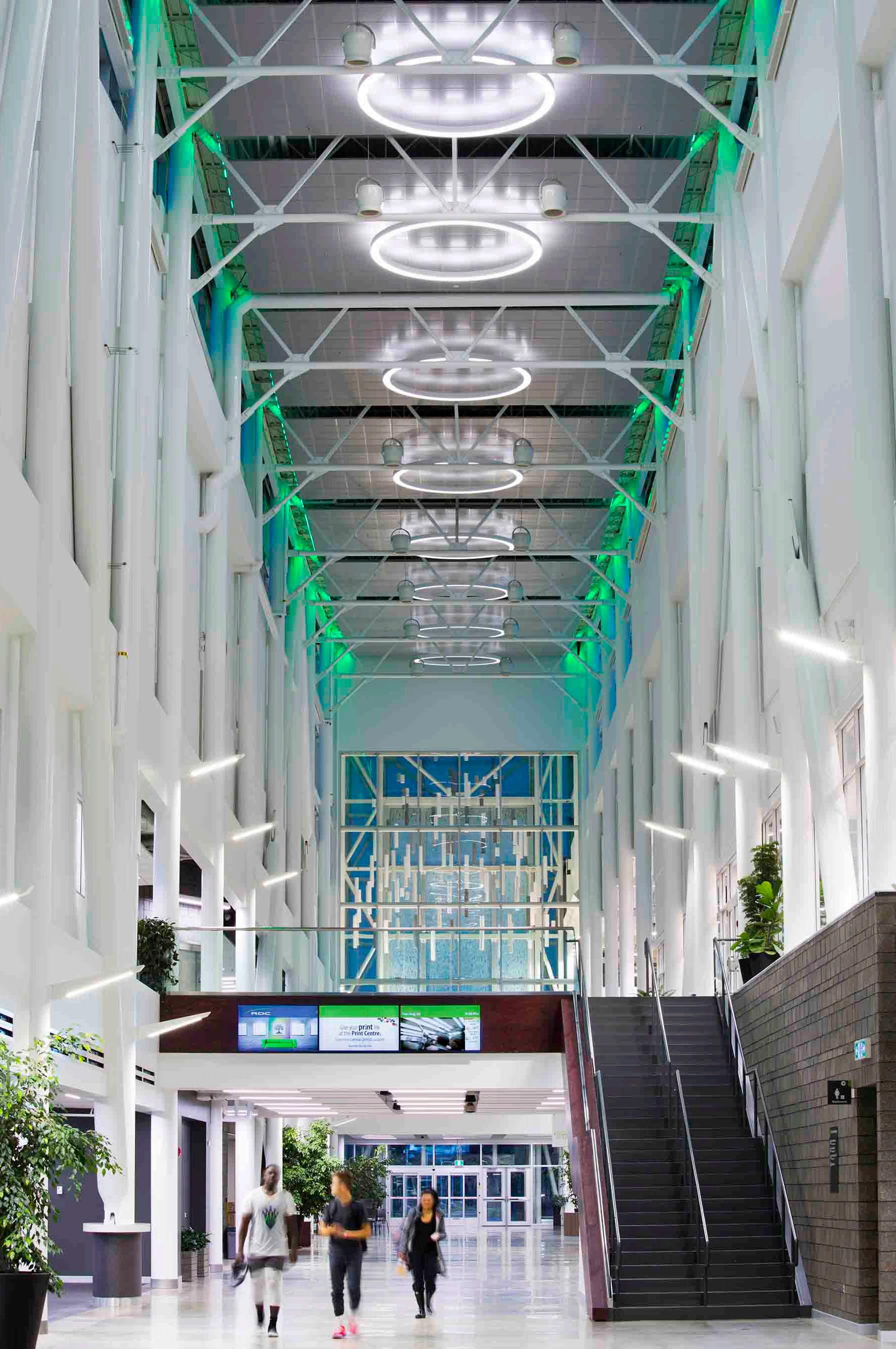
One of our integral design decisions was in how we were going to create not only a successful sports and recreation facility, but how can we turn such a facility into a beacon for the city as well as travellers along the adjacent highway. Through studying many foam massing models, we decided to highlight the main circulation corridor. Dubbed the “Great Hall”, a volume of light was created that was used as both our beacon but also a physical wayfinding for users within the space.
PROFESSIONAL PRACTICE
14
Exterior form of the “Great Hall” connecting all programs within the project
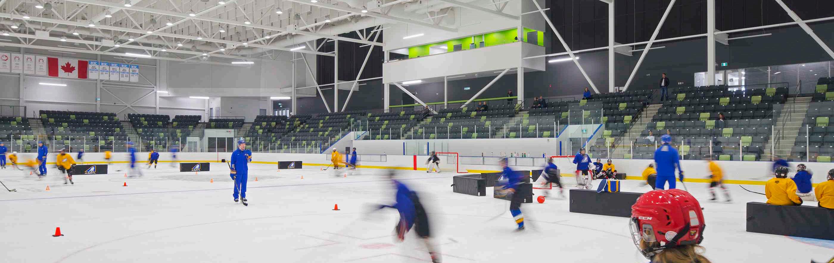
Olympic Size rink, convertable to a Hybrid/NHL Surface
As both a public space for the City of Red Deer and a facility of Red Deer College, it was important to us to give the community a strong connection and sense of identity within the project. Highlighted in our gymnasium, the Kings & Queens of Red Deer College were given a space where they could fully embrace the culture of their school, while taking a high level of pride in their athletics and academics.
 GARY W. HARRIS CANADA GAMES CENTER
Double gymnasium that seats up to 1,200 spectators 15
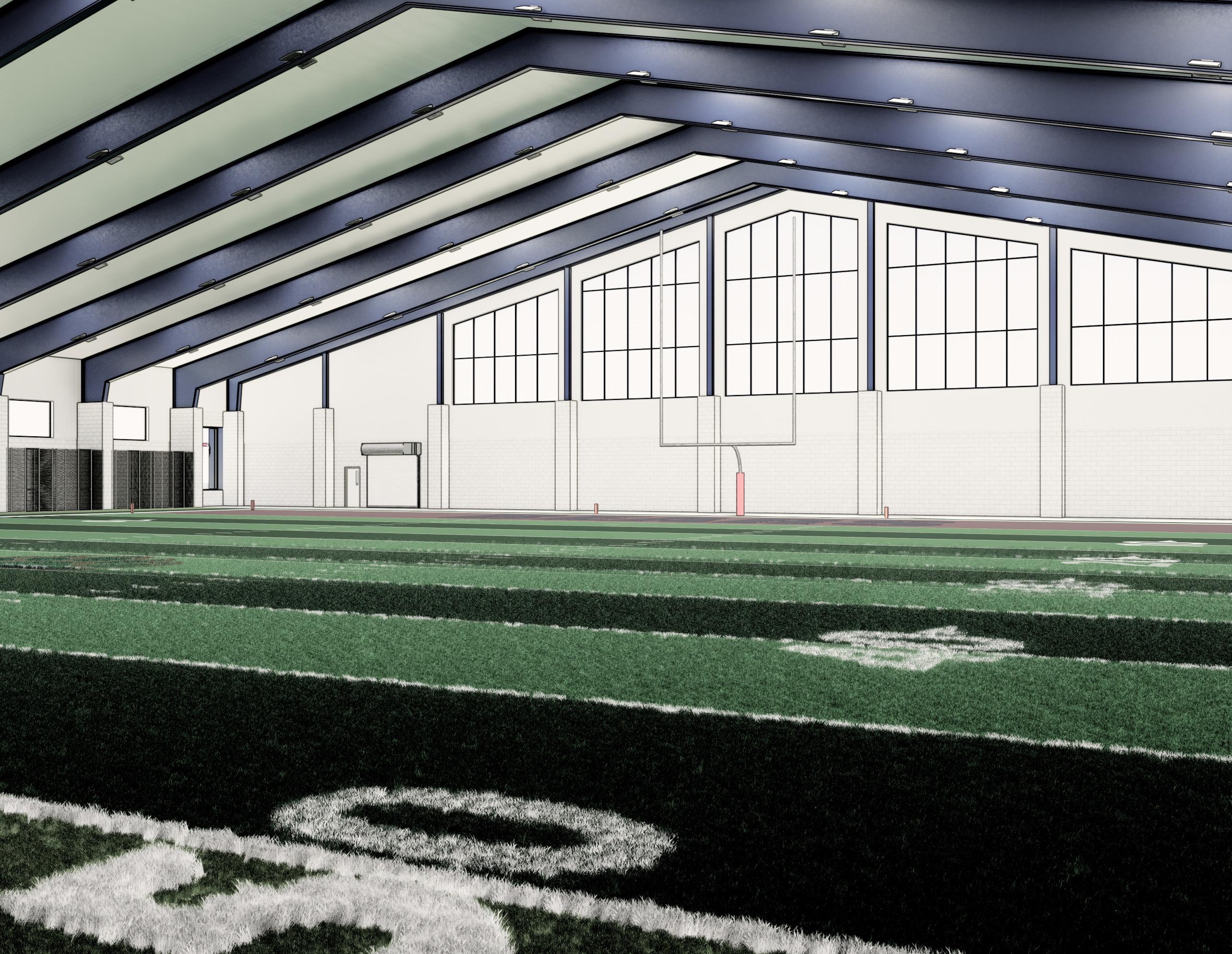
The Bear Field House is a dedicated athletic facility for Berkley High School, that will house a 32,000 SF multisport field, an indoor track lane, a weight room, and more. Clad with limestone and brick masonry, the Bear Field House takes hints from the late 1940’s contemporary high school across the street, and uses expansive glazing and a clean pre-fabricated structural system to step the school into the current era.
BERKLEY BEAR FIELD HOUSE
Firm: Stantec Architecture
Client: Berkley Schools
Type of Project: Academic, Sports & Recreation
Location: Berkley, MI, USA
Role: BIM Manager, Designer
Technical Skills: As the projects BIM Manager, my role began once the project had completed conceptual design and began documentation. This role involved establishing the project coordinates and geolocation, cartooning the set in preparation for Schematic Design, setting project templates, and managing access and coordination items with our consultant team.
16
17
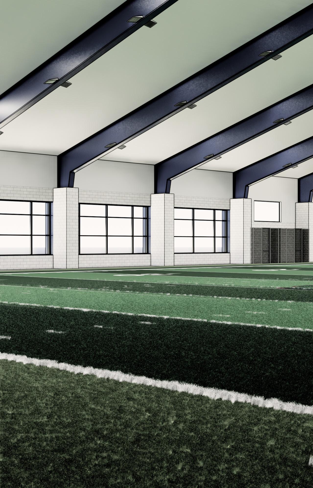
The most space in the project was dedicated to the practice field. Close to half the size of a football field, the practice field will not only offer practice to the football team, but track & field, baseball, softball, soccer, and more. First Level - Floor Plan
19' 11' 180' 10' 17'-6" 25 81' 72' 300' 215' 180' 160' FC FC FC FC FC G UP GENERAL FLOOR PLAN NOTES 1. FIRST FLOOR REFERENCE ELEVATION 100 - XXX.XX (XXXX DATUM, REFER TO CIVIL). 2. ALL DIMENSIONS ARE FROM COLUMN REFERENCE LINE TO FACE OF PARTITION, UNLESS NOTED OTHERWISE. 3. REFER TO CODE DRAWINGS (G000 SERIES) FOR LOCATIONS & EXTENT OF RATED ASSEMBLIES. IF PARTITION DESIGNATION DESCREPENCY OCCURS BETWEEN THE CODE DRAWING & THE FLOOR PLANS; PROVIDE THE PARTITION TYPE INDICATED W/ THE MOST SEVERE REQUIREMENTS. 4. REFER TO DRAWING A421 FOR ALL INTERIOR PARTITION TYPES. 5. ALL MASONRY PARTITIONS ARE TYPE M08 UNLESS NOTED OTHERWISE. 6. ALL GYPSUM PARTITIONS ARE TYPE C10 UNLESS NOTED OTHERWISE. 7. PROVIDE TILE BACKER BOARD AT ALL WALL LOCATIONS SCHEDULED TO RECEIVE TILE FINISHES. REFER TO ROOM FINISH SCHEDULE FOR LOCATIONS. 8. REFER TO DRAWING G021 FOR WALL ACCESSORIES AND VISUAL DISPLAY SURFACE MOUNTING INFORMATION 9. PROVIDE FRT WOOD BLOCKING AT ALL WALL MOUNTED SHELVING, CABINETS, TOILET, PARTITIONS, GRAB BARS, HAND RAILS, EQUIPMENT, ETC. 10. REFER TO ROOM FINISH SCHEDULE FOR WALLS TO RECEIVE ABUSE RESISTANT GYPSUM BOARD. 11. PROVIDE FRT PLYWOOD BACKING PANELS IN ALL MDF, IDF, TELECOM, AND ELECTRICAL ROOMS FROM 1'-0" AFF TO 9'-0" AFF ON ALL WALLS. 12. FOR HOUSEKEEPING PADS, ALL DIMENSIONS ARE FROM COLUMN REFERENCE LINE TO CENTERLINE OF CONCRETE PAD, UNLESS NOTED OTHERWISE. CONCRETE PAD SIZES INDICATED ARE BASED ON SPECIFIC MANUFACTURER S EQUIPMENT, COORDINATE W/ MECHANICAL, PLUMBING &/OR ELECTRICAL TRADE CONTRACTOR TO OBTAIN PURCHASED EQUIPMENT PAD REQUIREMENTS. B1 A301 D1 A301 A1 A301 C1 A301 A401 A1 A401 D1 1 2 3 4 5 6 7 8 9 10 11 B C D E F G H I 12 13 A J A402 A5 A402 A2 102.1 102.2 102.3 106.1 106.2 106.3 108.1 S100.1 107.1 112.4 112.2 105.2 105.3 105.5 105.4 112.1 105.1 C100.1 112.3 101 ENTRY VEST 102 MAIN LOBBY 103 TEAM MEETING C100 CORRIDOR 109 J/C 106 WEIGHT ROOM 111 FIRST AID 107 MEN 112 FIELD STORAGE 105 PRACTICE FIELD & TRACK S100 MEZZ STAIR 10'-8" TYP TYP 2'-8" TYP 4'-6" TYP 3'-8" TYP 3'-4" TYP 3'-8" 10'-8" TYP 21'-4" TYP 24'-0" 24'-0" 24'-0" 24'-0" 16'-0" 21'-6" 24'-0" 24'-0" 24'-0" 24'-0" 24'-0" 24'-0" 24'-0" 21'-6" 6'-0" 3'-0" 6'-0" 12'-0" 3'-0" 51'-0" 3'-0" 6'-0" 1'-0" 1'-0" 8 3/4" 8 3/8" 10 1/2" 3'-4" 3'-3 1/2" 6'-4" 3'-3 1/2" 3'-4" 10 1/2" 8 3/8" 8'-0" 6'-4" 3'-4" 13'-9 3/8" 1'-4" 9'-6" 6'-4" 6'-10" 6'-4" 10'-0" 2'-0" 3'-0" 2'-0" 16'-0" 24'-0" 24'-0" 24'-0" 24'-0" 24'-0" 14'-0" TRTMNT TAPING ICE RACK 108 WOMEN 110 ELEC RM 104 OFFICE/ STORAGE BENCHES BENCHES SUSPENDED SHELF ELECT WATER HEATER SERVICE SINK 24"x24" RE:PLUMB TARGET LOCATION FOR PLUMBING VENT UP THRU MEZZ IN-LINE EXHAUST FAN ABOVE CEILING PROVIDE EXHAUST LOUVER AT EXT WALL FIRE PROTECTION RISER ASSEMBLY DOMESTIC WATER METER ASSEMBLY 104.1 109.1 110.1 111.1 103.1 103.2 101.2 101.3 101.1 216'-0" O.T.O. MASONRY 24'-0" 74'-8" 4'-0" A402 B3 A402 A1 A402 B1 A3 A401 B1 A401 C1 C3 M.O. 3'-4" 2'-0" M.O. 10'-0" 20'-1" M.O. 6'-4" 74'-8" M.O. 6'-4" M.O. 6'-4" M.O. 16'-0" M.O. 6'-4" 40'-0" STOREFRONT SYSTEM 142'-0" STOREFRONT SYSTEM 5'-10" 13'-4" 4'-10" 8'-10" 8'-10" LARGE RELIEF AIR LOUVER RETURN LOUVER (ABOVE) RE: MECH LARGE RELIEF AIR LOUVER RETURN LOUVER (ABOVE) RE: MECH ELECT CUH RE: MECH LARGE DIA. FABRIC SUPPY DUCT ABOVE, RE: MECH GAS METER ASSEMBLY LARGE DIA. FABRIC SUPPY DUCT ABOVE, RE: MECH AIR HANDLING UNITS ACCU RE: MECH TRANSFORMER RE: ELEC ELECT. CUH(S) ELECT. UH(S) FDC (VERIFY W/ CITY) RE: MECH CIVIL AIR HANDLING UNITS OPERABLE NETTING ATTACHED TO TOP OF WALL AND UNDERSIDE OF ROOF INLINE EXHAUST FAN EXHAUST LOUVER AT EXTERIOR WALL SECURE FENCING AROUND THE WEIGHT ROOM AREA SECURE FENCING FOR TEAM STORAGE, TYP SECURE FENCING FOR TEAM STORAGE, TYP MB 10' MB 10' 14 COUNTER AND CABINETS EWC BATTING CAGE DROP-DOWN NETTING BATTING CAGE DROP-DOWN NETTING FLOOR BOX FOR PITCHING MACHINE IN TURF, RE: ELECT OPERABLE NETTING ATTACHED TO TOP OF WALL AND UNDERSIDE OF ROOF ORIGINAL SHEET -ARCH E1 A B C D E Consultant Permit/Seal PRELIMINARY NOT CONSTRUCTION Not for permits, purposes. This document completed or checked information Revision: File Name: N/A Dsgn.Chkd. Dwn. Project No.: Title Scale: Drawing No. 2 3 4 5 6 3/14/2024 2:31:16 PM As indicated <Pick location in Project Information> Author Designer BERKLEY PUBLIC SCHOOLS 214100662 FIRST LEVEL PLAN 3/32" = 1'-0" A1 FIRST LEVEL -FLOOR PLAN
18
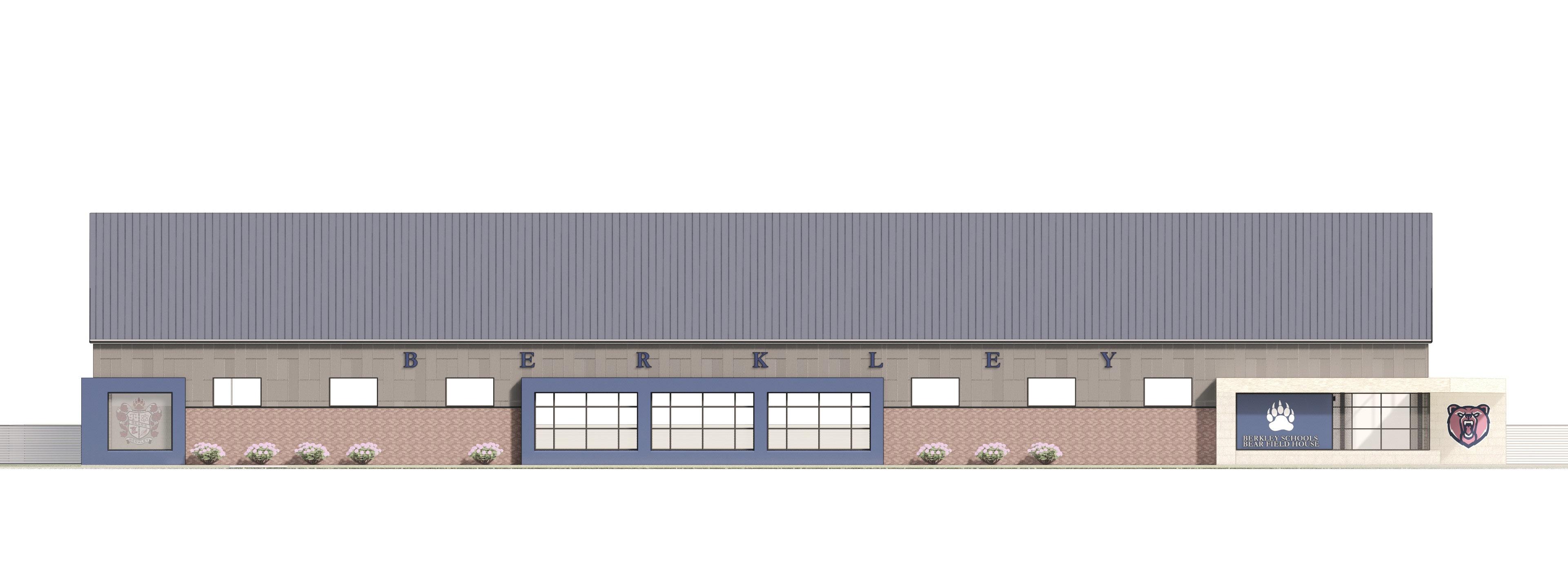
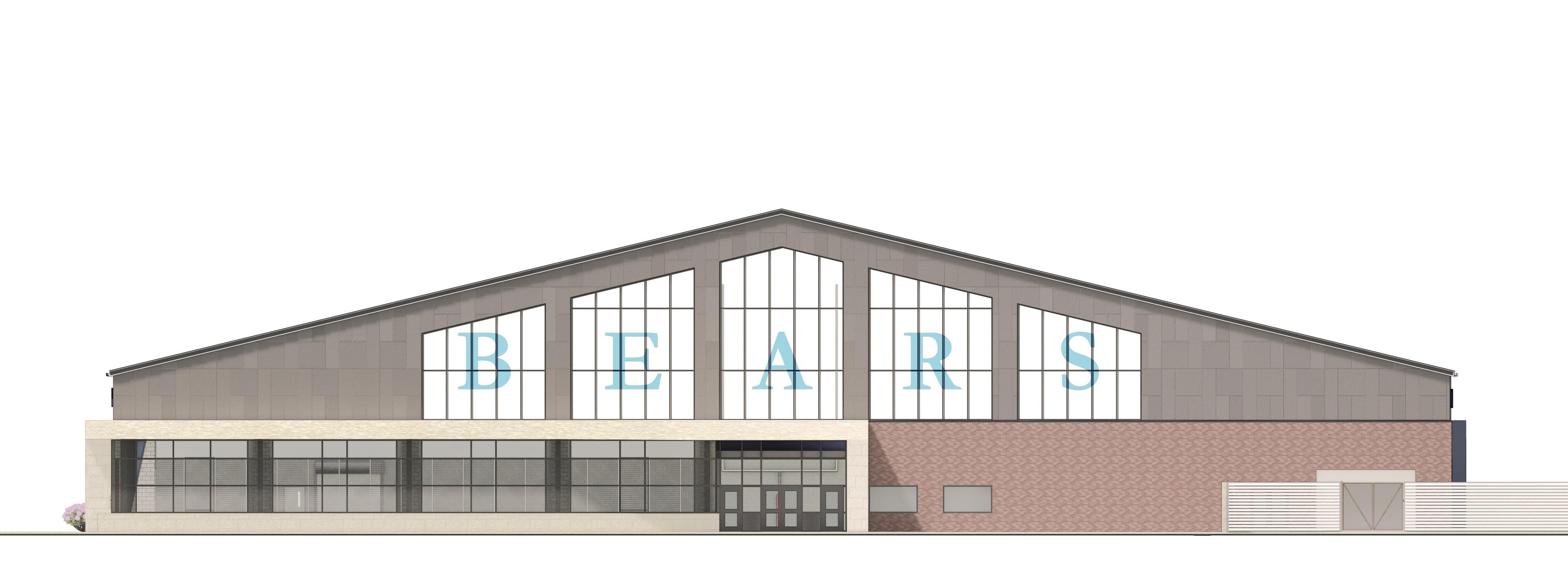
While a large focus of the project was on the interior program, much of the buildings exterior design was focused on wayfinding and branding. For any group, but especially high schoolers, branding becomes a big part of their identity. Students will still associate themselves with their high school long after graduation, and our design wanted to reflect that spirit.
 South Elevation
19
East Elevation
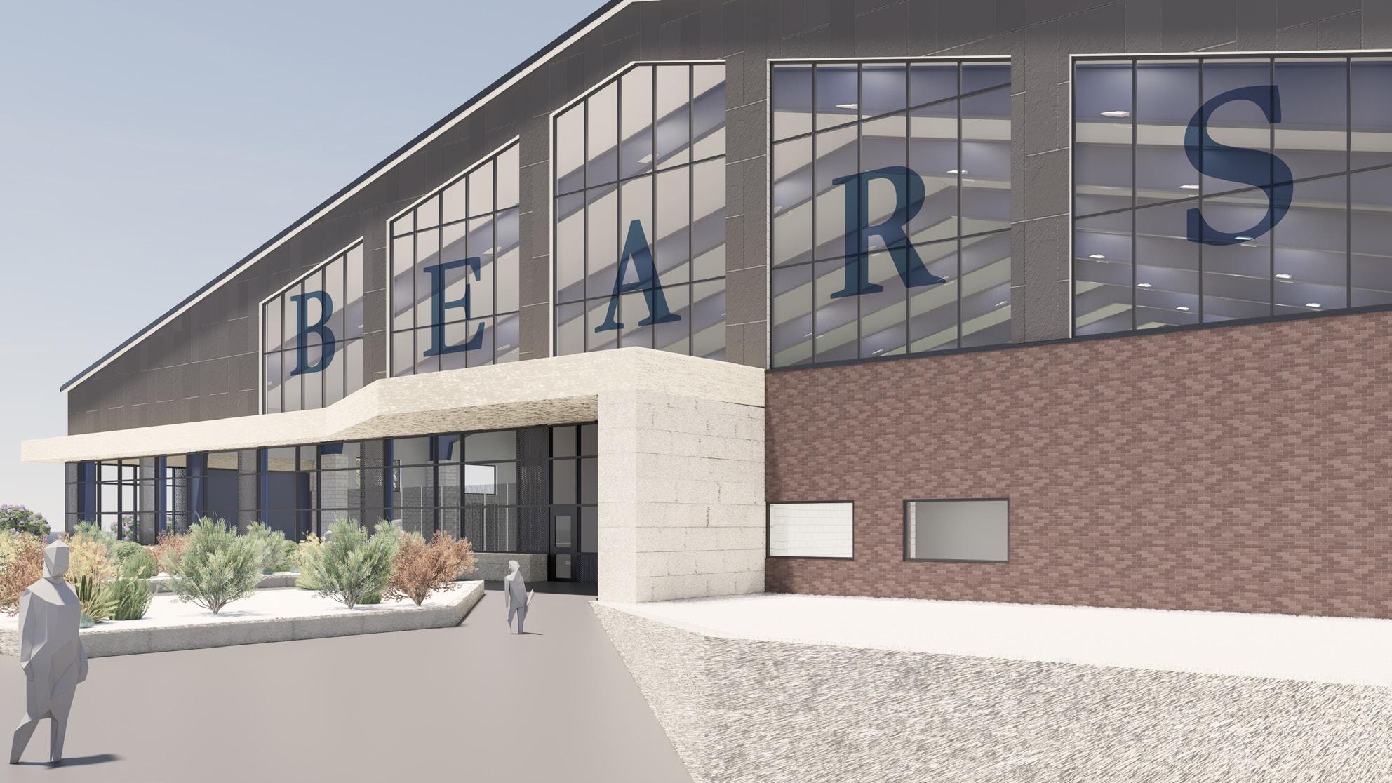
Similar to the rest of the school, we used a limestone tile to mark all entryways as our main form of wayfinding.
Much of my role came from coordinating the structure with our engineers and fabricators, ensuring not only that the design stayed in line with our concept but that all our various programs would succeed within the space.
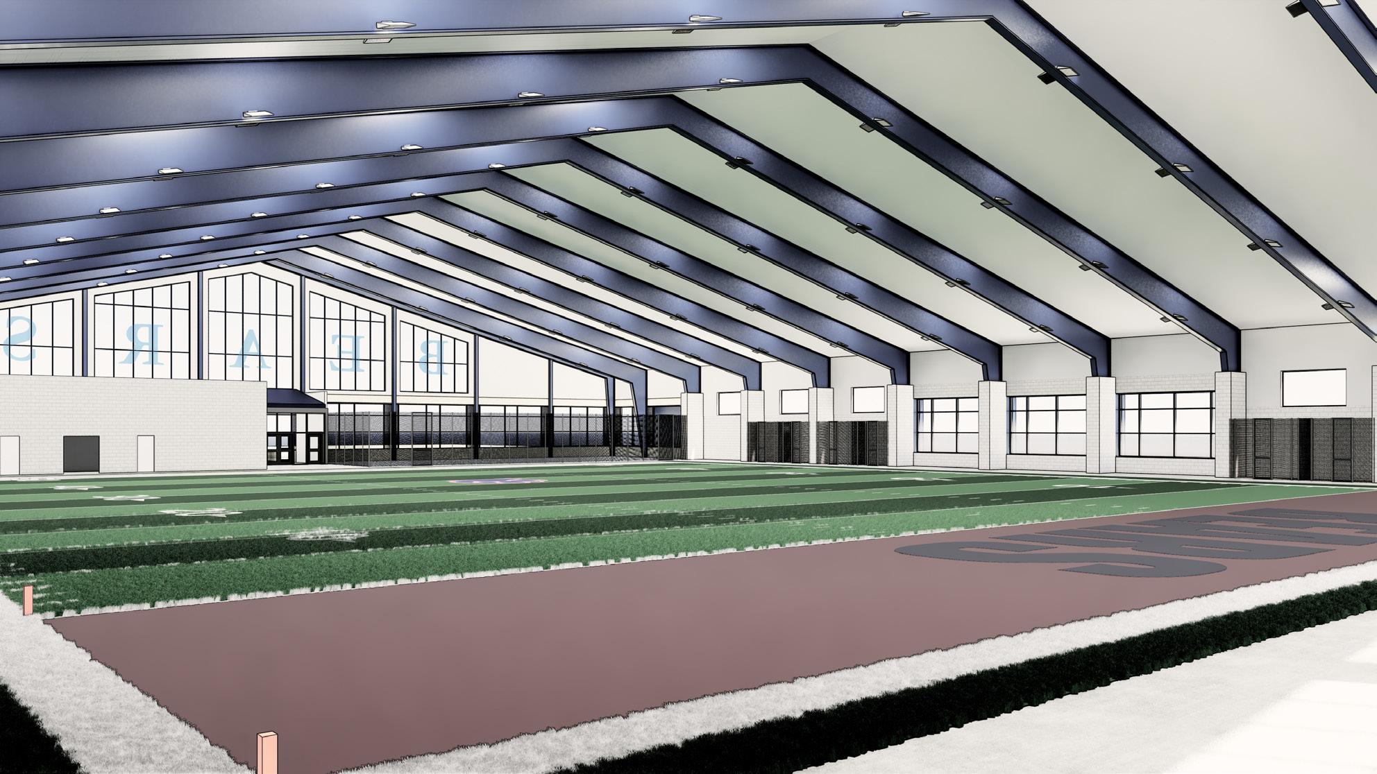
Interior rendering showing pre-fabricated steel structure
Rendering of Main Entryway
20
Reflected Ceiling Plan showing the expansive but column-less steel framing
GENERAL CEILING PLAN NOTES 1. REFER TO FLOOR PLANS & INTERIOR ELEVATIONS FOR WALL MOUNTED FIXTURES DEVICES, ETC. 2. REFER TO MECHANICAL, ELECTRICAL & TECHNOLOGY DRAWINGS FOR QUANTITY TYPE OF CEILING MOUNTED FIXTURE, DEVICES, ETC. 3. CENTER ALL LIGHTS, DIFFUSERS, ETC. IN CEILING TILES UNLESS NOTED OTHERWISE 4. TYPICAL CEILING HEIGHT SHALL BE 9' - 0" AFF UNLESS NOTED OTHERWISE - REFER TO FINISH SCHEDULE FOR HEIGHTS 5. TYPICAL HEIGHT FOR GYPSUM BOARD BULKHEADS SHALL BE -10 AFF, UNLESS NOTED OTHERWISE. 6. GYPSUM BOARD SOFFIT ELEVATIONS ARE GENERAL IN NATURE, THOSE ABUTTING CURTAIN WALL ARE TO ALIGN WITH TOP AND BOTTOM OF MULLION AS INDICATED IN SECTION DETAIL 7. UNDESIGNATED PAINTED GYPSUM BOARD SOFFITS & CEILINGS (UNLESS OTHERWISE NOTED) TO BE MARK PX 8. ALL SHADES ARE MANUAL UNLESS NOTED OTHERWISE 9. EXACT LOCATIONS FOR PROJECTOR MOUNTS CEILING MOUNTED MANUAL SCREENS ARE TO BE FIELD VERIFIED TO ACHIEVE THE OPTIMUM PERFORMANCE. COORDINATE W/ TECHNOLOGY TRADE CONTRACTOR. GYPSUM BD ACCESS PANEL PAINT TO MATCH CEILING TYPICAL ROLLER SHADE RECESSED PROJECTION SCREEN LINEAR PENDANT LIGHT FIXTURE RE: ELECTRICAL DOCUMENTS RECESSED LIGHT FIXTURE RE: ELECTRICAL DOCUMENTS RECESSED CAN LIGHT FIXTURE RE: ELECTRICAL DOCUMENTS SUPPLY DIFFUSER RE: MECHANICAL DOCUMENTS RETURN GRILLE RE: MECHANICAL DOCUMENTS EXHAUST GRILL RE: MECHANICAL DOCUMENTS TRACK LIGHTING FIXTURE RE: ELECTRICAL DOCUMENTS SURFACE MOUNTED INDUSTRIAL LIGHT FIXTURE RE: ELECTRICAL DOCUMENTS INDUSTRIAL PENDANT LIGHT FIXTURE RE: ELECTRICAL DOCUMENTS EXIT SIGN RE: ELECTRICAL DOCUMENTS LINEAR SUPPLY DIFFUSER RE: MECHANICAL DOCUMENTS RADIANT PANEL RE: MECHANICAL DOCUMENTS LAY-IN CEILING LEGEND DSF DESTRATIFICATION FANS, SUSPENDED BELOW PRIMARY STRUCTURE RE: MECHANICAL DOCUMENTS LED INDIRECT LIGHT MOUNTED TO PEMB STRUCTURE RE: ELECTRICAL DOCUMENTS CEILING CONSTRUCTION NOTES 1. XX 2. XX 3. XX B1 A301 D1 A301 A1 A301 D1 SD120 1 2 3 4 5 6 7 8 9 10 11 B C D E F G H 12 13 A J 112 FIELD STORAGE 105 PRACTICE FIELD & TRACK 111 FIRST AID 107 MEN 103 TEAM MEETING S100 MEZZ STAIR 110 ELEC RM 101 ENTRY VEST 102 MAIN LOBBY 106 WEIGHT ROOM 108 WOMEN 104 OFFICE/ STORAGE 109 J/C C100 CORRIDOR SUPPORT FOR OPERABLE NETTING ATTACHED TO PEMB STRUCTURE AND SUSPENDED FROM CEILING FIELD GOAL SUSPENDED FROM CEILING NETTING ABOVE BATTING PRACTICE AREAS 3'-0" 8'-0" 8'-0" 3'-0" 4'-8" ACT 11' -8" ACT -0" ACT9' -0" ACT8' -0" ACT10' -0" ACT8' -0" ACT9' -0" GYP 14' -11" LARGE DIA. FABRIC SUPPY DUCT ABOVE, RE: MECH LARGE DIA. FABRIC SUPPY DUCT ABOVE, RE: MECH DIRECTLY APPLIED FINISH SYSTEM AT CANOPY SOFFIT WT-1 WT-1 14 ORIGINAL SHEET -ARCH E1 A B C D E Consultant Permit/Seal PRELIMINARY NOT CONSTRUCTION Not for permits, pricing purposes. This document completed or checked information or Revision: File Name: N/A Dsgn.Chkd. Dwn. Project No.: Title Scale: Drawing No. 1 2 3 4 5 As indicated <Pick location in Project Information> Stantec Architecture Inc. Author Designer BERKLEY PUBLIC SCHOOLS 214100662 FIRST LEVEL PLAN 3/32" = 1'-0" A1 FIRST LEVEL -CEILING PLAN DESTRAT FAN, RE: MECH, TYP
21
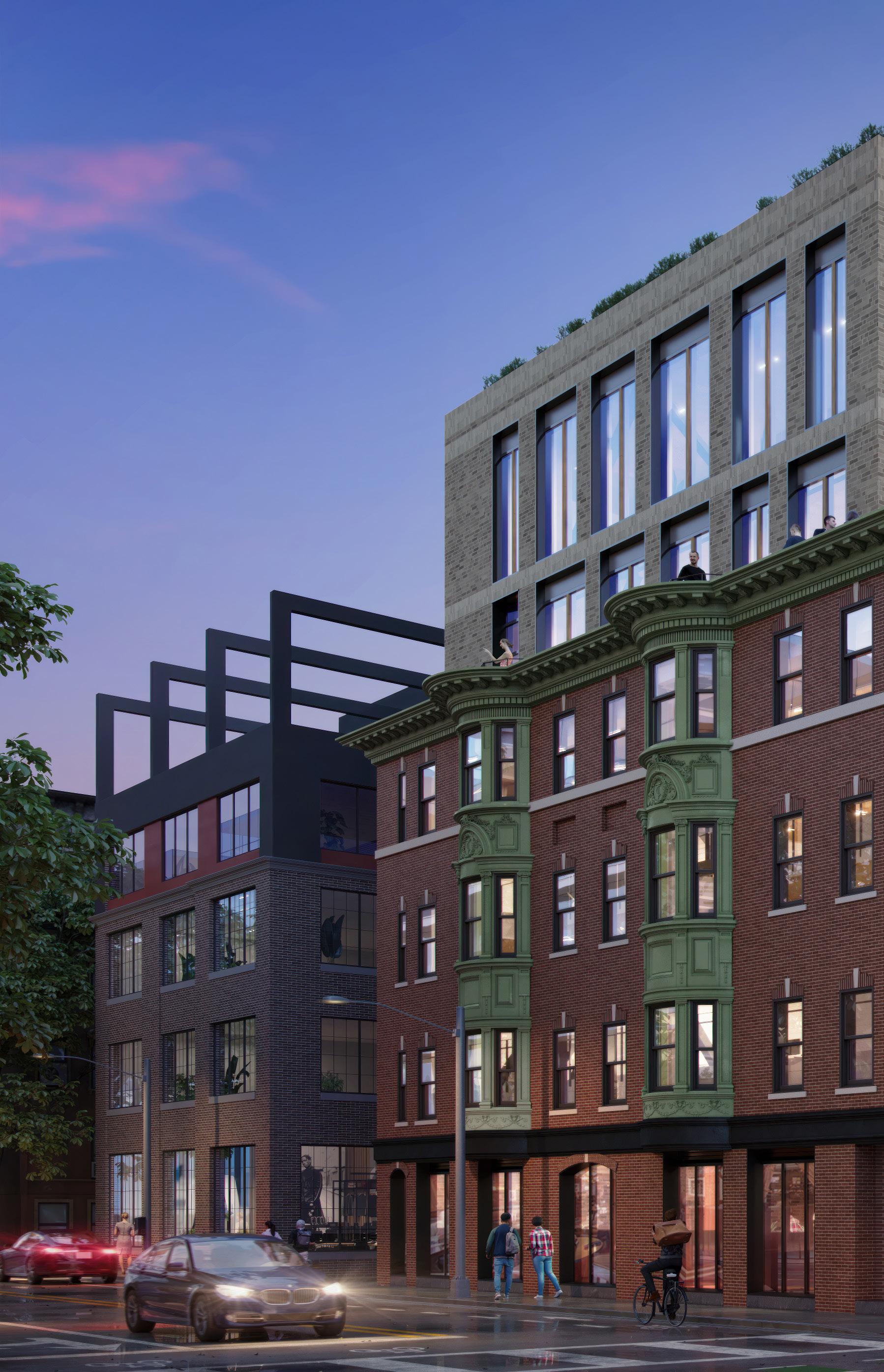
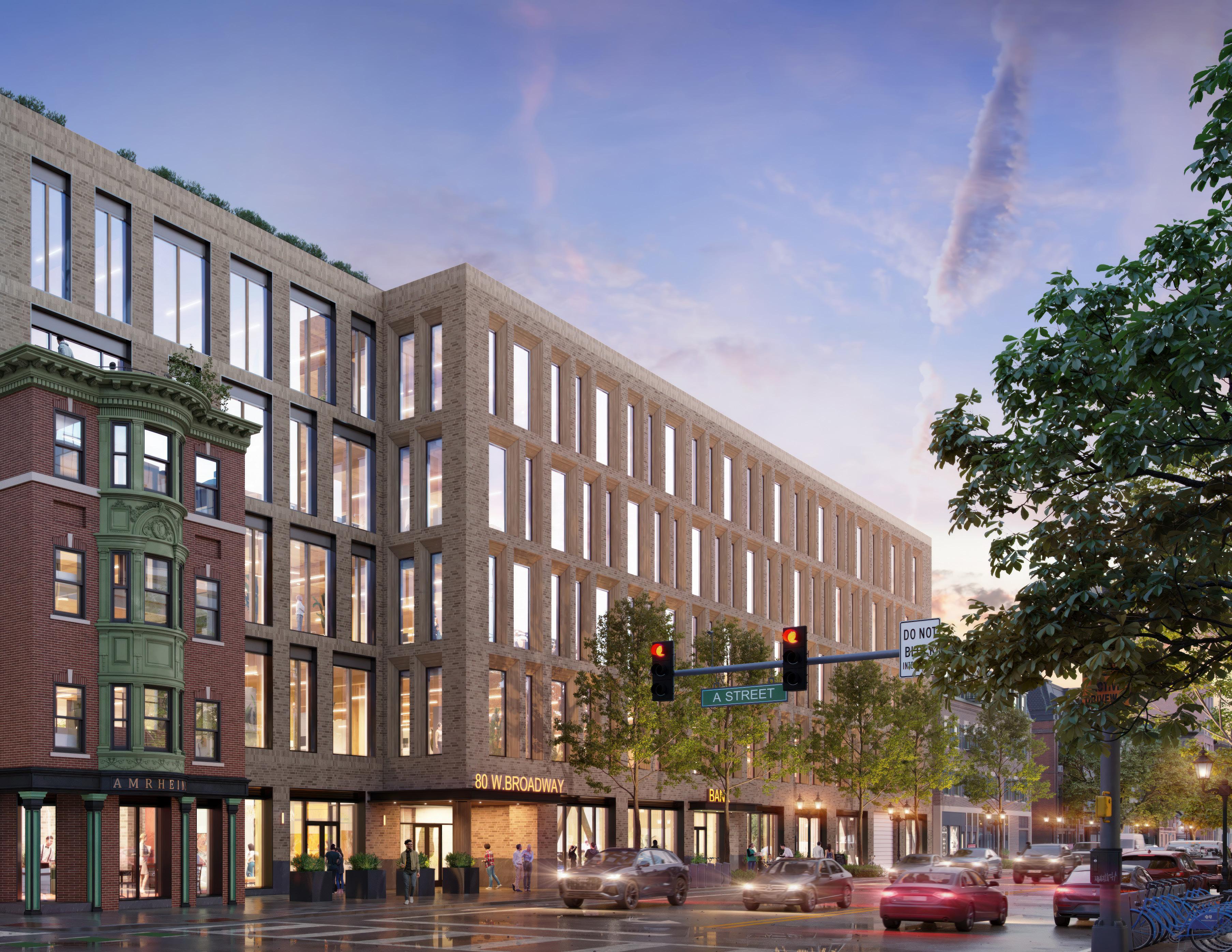
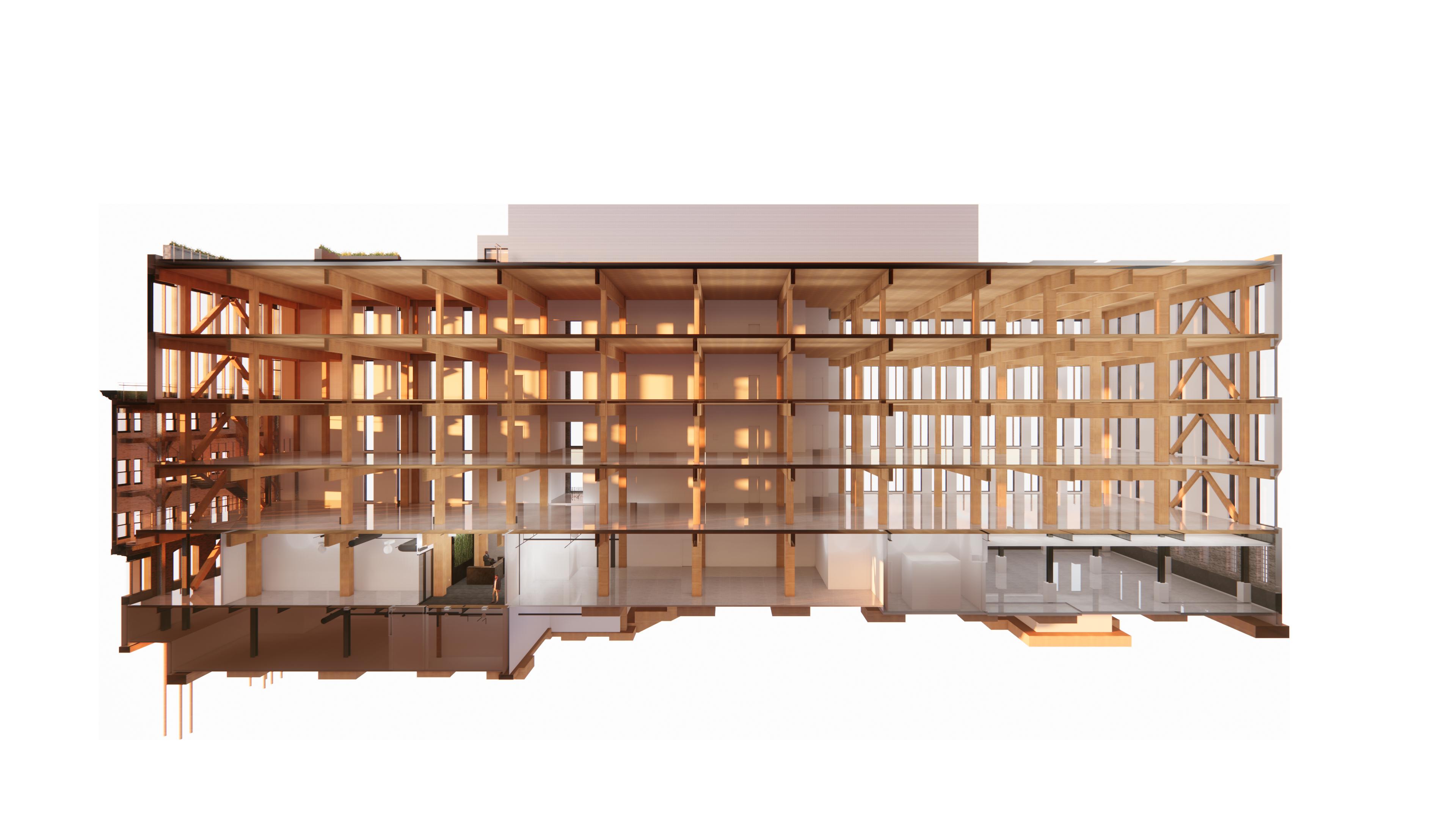
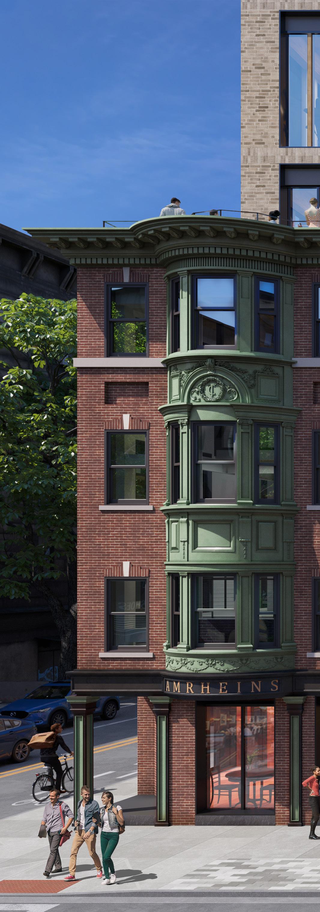
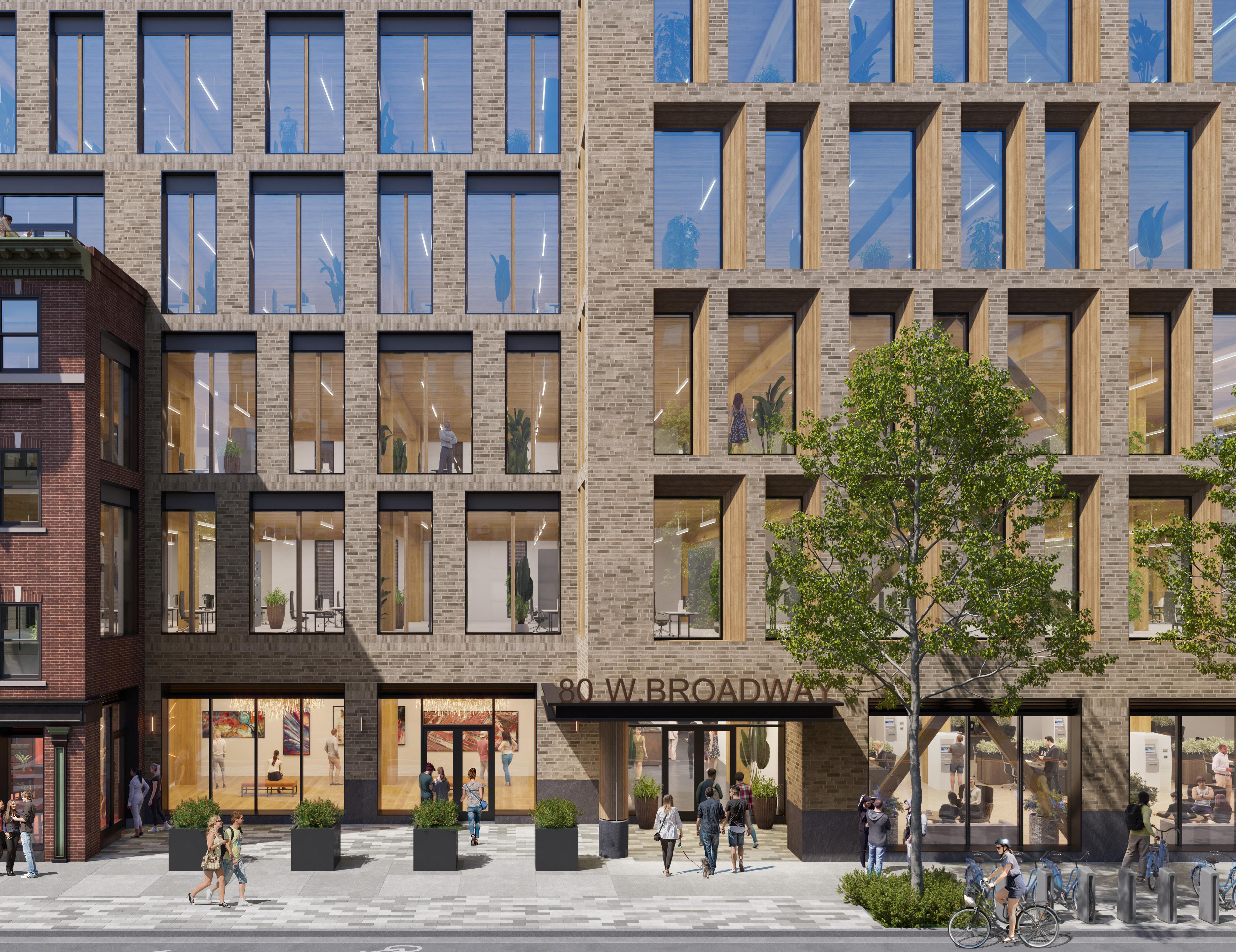
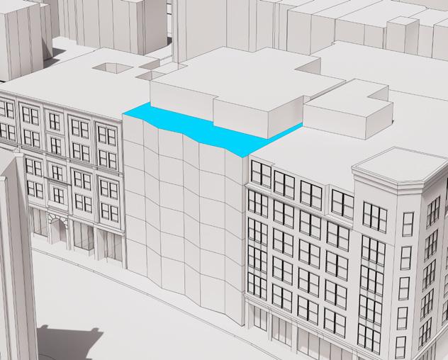
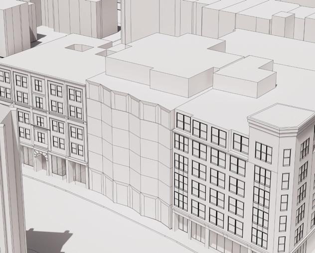
Located at the northern gateway to South Boston, 80 West Broadway brings 100,000 SF of commercial/office space into the neighbourhood while breathing new life into a historic and cherished storefront. The existing brownstone has been a cornerstone of South Boston for over a century, and is vital to maintaining the character of the community within this project. The architectural form steps back at the corner, allowing the existing structure to take center stage. Jogging back out at the lobby, prominent wood-grained window frames are introduced at select angles to both maximize sunlight during low sun seasons while also providing sun shading to intense late-afternoon sun. The exterior language also begins to hint at the Cross-Laminated Timber (CLT) structure throughout the interior, which will be one of Boston’s first built CLT projects. This project will achieve LEED Gold Certified and also features a 700-Module Solar PV Array.
80 WEST BROADWAY
Firm: Stantec Architecture
Client: Shorenstein
Type of Project: Commercial/Office, Adaptive Reuse
Location: Boston, MA, USA
Role: Designer and BIM Manager
Technical Skills: As the Lead BIM Manager for the project, my job has been leading the digital design team while also leading coordination efforts with all of our consultants on the project. This included coordinating with our Mass Timber manufacturers in Austria and walking through sequencing and detailing with our construction team. Being in a prominent area of South Boston, much of my earlier work was assisting in both permitting and public process with various groups around the city and ensuring that our design would fit seamlessly within the context of South Boston.
22
23
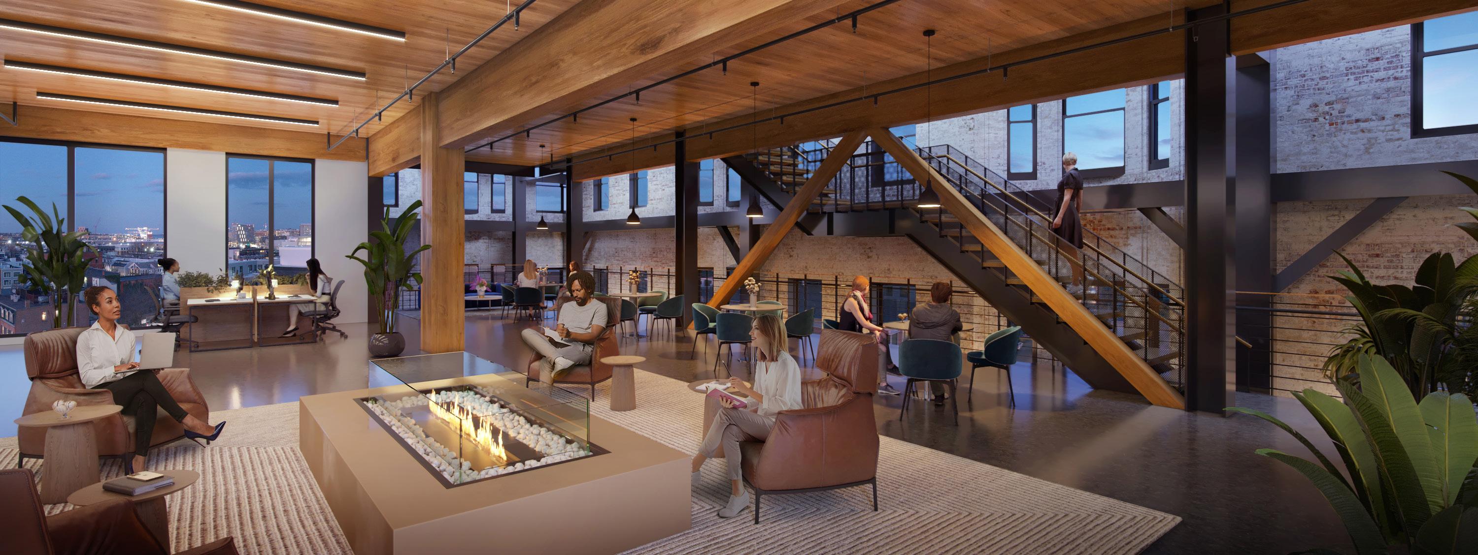
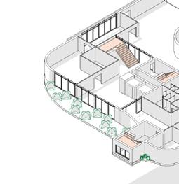
As a Core & Shell project, much of our focus was on the exterior detailing. This was particularly challenging, however the final result will make for a fantastic project. Although we weren’t able to connect our new CLT slabs with the existing facade, this gave us an opportunity to create an open atrium where old meets the new. We have designed a connecting feature stair as an Design Alternate, on the chance that a single tenant will lease multiple floors.
PROFESSIONAL PRACTICE
24
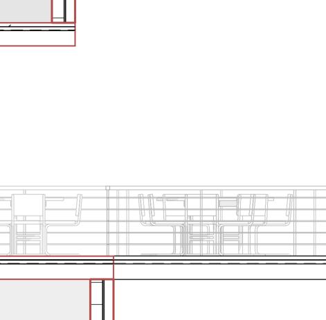
Due to the exposed CLT structure, most of our HVAC will also be exposed. As the Lead BIM Coordinator of the project, it has been a large focus of mine to ensure that the layout of all our mechanical duct work and plumbing remains organized as the users will be able to see all the bones of this building. It has been a fun challenge and an effort well worth it in order to pursue a CLT structural system.
The communicating stair would be a great addition to the space, if desired. This will allow tenants to walk up next to the restored brick and come face-to-face with the older history and charm of their new space.


DN B C D A.7 C.5 A-091 4 11 TREADS @ 11" EACH 10'-1" 7'-11" 10 TREADS @ 11" EACH 9'-2" 4'-11" 3'-7" LEVEL 2 46'-8" LEVEL 3 60'-0" LEVEL 4 73'-4" B C D A.5 A.7 C.5 L4 TERRACE T.O. SLAB 72'-2" 13'-4" PTD STEEL RISER SOLID WOOD TREAD SOLID WOOD LANDING PTD METAL CANE DETECTION RAIL CABLE RAIL W/ CONTINOUS WOOD HANDRAIL 11 RISERS 6'-4 1/2" 12 RISERS 6'-11 1/2" LEVEL 2 46'-8" LEVEL 3 60'-0" 73'-4" L4 TERRACE T.O. SLAB 72'-2" 1. THIS ADD-ALTERNATE IS IN-LIEU OF THE FULL-HEIGHT INTERIOR STOREFRONT PARTITION ON LEVEL 3 (B.O.D. AS SHOWN ON LEVEL 3 FLOOR PLAN). 2. CONTRACTOR TO COORDINATE ADD-ALTERNATE & DEDUCT-ALTERNATE SCOPE WITH APPROPRIATE SUBCONTRACTORS. © 2018 Stantec A B ORIGINAL SHEET -ARCH E1 1 2 / 2 2 0 2 2 5 0 2 4 9 P M BIM 360 1/8" = 1'-0" A-091 1 COMMUNICATING STAIR 1/8" = 1'-0" A-091 2 COMMUNICATING STAIR SECTION A 1/8" = 1'-0" A-091 4 COMMUNICATING STAIR SECTION B A-091 5 3D VIEW -CONNECTING STAIR W T 3 4 5 6 7 A B C A.5 A.7 C.5 MAIN LOBBY 100 BIKE ROOM 122 VESTIBULE 120 STAIR STA-01 ELEV. LOBBY L100 CLT 01 CLT 01 CLT 01 FA ALL EXPOSED HVAC, FP, PIPING, CONDUIT, U.O.N. FA 90 ALL EXPOSED HVAC, FP, PIPING, CONDUIT, U.O.N. FA 90 ALL EXPOSED HVAC, FP, PIPING, CONDUIT, U.O.N. A-751 LINE OF RECEPTION DESK BELOW. REFER TO DETAILS FOR LIGHTING LOCATIONS TENANT RISER CL. 102-9'-0" FA-90FA-FA8'-0" FA-11 MEN'S 104 TEL/DATA RISERS 103 A-820 A-820 EL-2 ELEV EL-1 ELEV A-016 SimP2 P2 P2 S5 3'-0" LINE OF BANQUETTE BELOW. REFER TO DETAIL FOR LIGHTING LOCATION. S12B S12A S11 T1 T1 S4 S4 100A LOBBY VESTIBULE R2 R2 R2 R2 W2 W2 R3 R2 EQ EQ E E Q S11 S113'-0" EQ EQ CLT 01 ALL EXPOSED HVAC, FP, PIPING, CONDUIT, U.O.N. FA 90 Q E Q EQ EQ EQ EQ EQ EQ EQ EQ A-820 A-820 A-820 S12F JAN. CL. SECURITY OFFICE A-820 A-820 A-820 S1 S1 S1 S14 S11 10'-5" FA-11 4'-0" 4'-0" 2018 Stantec Project No. Scale Notes Issued/Revision 6 A 4 B C D E Consultant PRELIMINARY NOT FOR CONSTRUCTION Permit/Seal ATHENS STREET A STREET PROJECT BIM 360 Stantec Architecture and Engineering 40 Water Street, 3rd Floor Boston, MA 02109 Tel: (617) 234-3100 www.stantec.com LEVEL 1 -AMENITY ENLARGED RCP A-712 80 WEST BROADWA 1/4" = 1'-0" A-712 1 LEVEL 1 -MAIN LOBBY -ENLARGED RCP 30% CONSTRUCTION DOCUMENTS 90% CONSTRUCTION DOCUMENTS 80 WEST BROADWAY
25
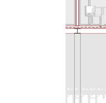
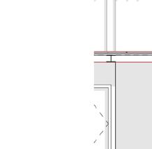
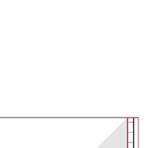
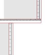
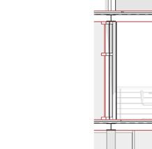
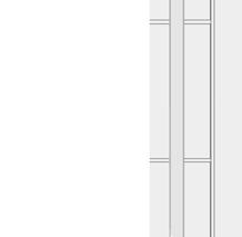
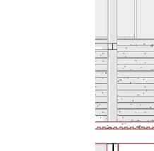
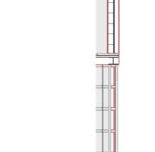
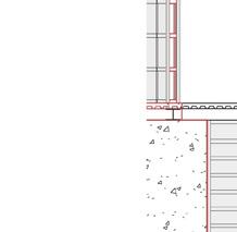
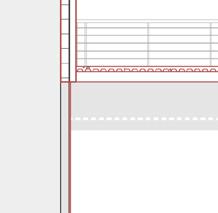
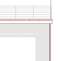
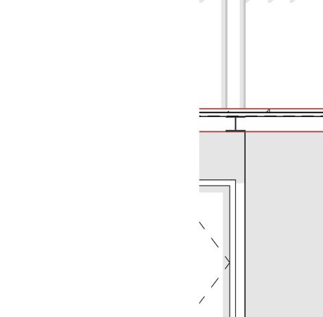
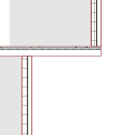
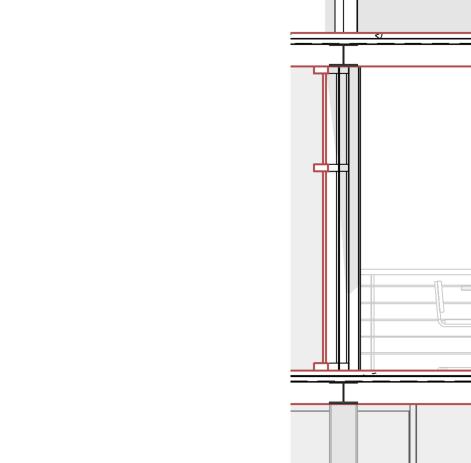
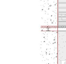
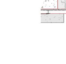
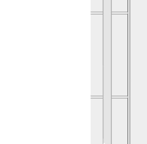
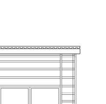
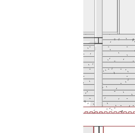
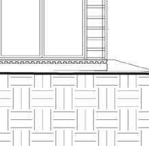
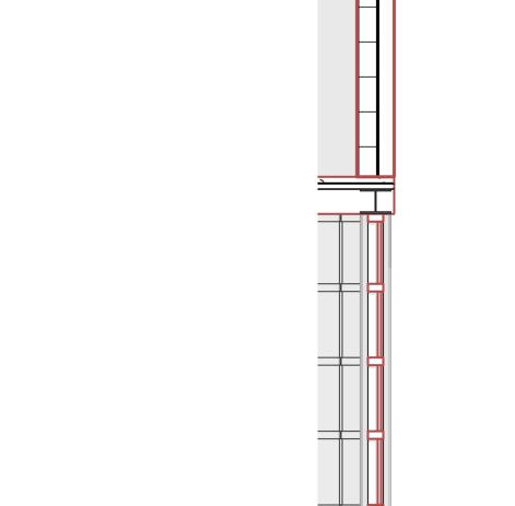
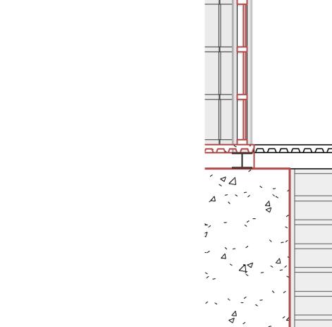
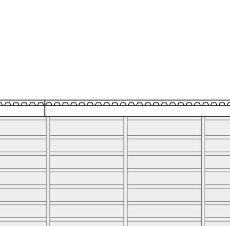
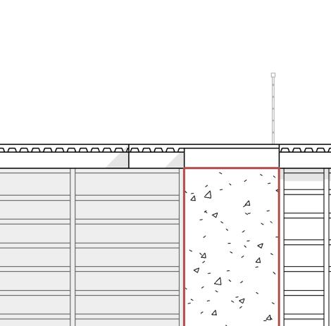
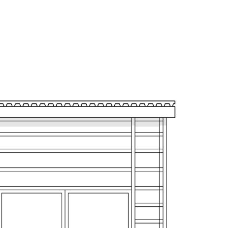
80 West Broadway will be one of Boston’s first Cross-Laminated Timber (CLT) buildings. Introducing an ambitious structural system while preserving an important storefront in South Boston has been a very ambitious but fun endeavor. Learning intricate details about facade preservation has been very instructional, while also learning the intricacies of negotiating design with emphatic neighbourhood associations.


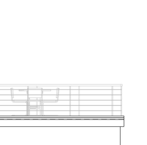
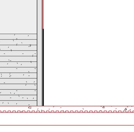
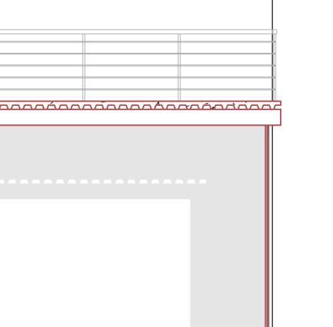
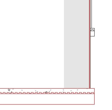
LEVEL 1B 30'-0" LEVEL 2 46'-8" LEVEL 3 60'-0" LEVEL 4 73'-4" LEVEL 5 86'-8" T.O. ROOF STRUCTURE 100'-8" LEVEL LL1 18'-0" 1 1.2 LEVEL 1A 31'-3" T/O FLOOR EL= 23'-10" 7'-5" 5'-10" 14'-0" 13'-4" 13'-4" 13'-4" 15'-5" 13'-3" A-411 A-411 A-502 4 TYP. A-503 1 TYP. T.O.S. DUNNAGE 105'-4" T102 TENANT T200 TENANT T300 TENANT T400 TENANT T500 TENANT L4 TERRACE T.O. SLAB 72'-2" ROOF TERRACE 102'-0" NON-OCCUPIED STORAGE SHELF TEMP. SHORING TO BE COORDINATED WITH GC TEMP. SHORING TO BE COORDINATED WITH GC TEMP. SHORING TO BE COORDINATED WITH GC EXS-1 A-300 BVS-1 A-300 A-411 TYP. A-504 1 TYP. A-504 TYP. A-504 4 TYP. LEVEL 1B 30'-0" LEVEL 2 46'-8" LEVEL 3 60'-0" LEVEL 4 73'-4" LEVEL 5 86'-8" T.O. ROOF STRUCTURE 100'-8" LEVEL LL1 18'-0" 1 1.2 14'-0" 13'-4" 13'-4" 13'-4" 15'-5" EXS-2 A-300 BVS-1 A-300 LEVEL 1A 31'-3" A-411 6 A-502 TYP. A-503 TYP. A-411 TYP. T.O.S. DUNNAGE 105'-4" 5'-9" 5'-10" 6'-10 3/4" T102 TENANT T200 TENANT T300 TENANT T400 TENANT T500 TENANT L4 TERRACE T.O. SLAB 72'-2" ROOF TERRACE 102'-0" NON-OCCUPIED STORAGE SHELF TEMP. SHORING TO BE COORDINATED WITH GC TEMP. SHORING TO BE COORDINATED WITH GC TEMP. SHORING TO BE COORDINATED WITH GC A-504 TYP. A-504 TYP. A-504 7 TYP. A-621 15 A-504 8 TYP. © 2018 Stantec 6 A 5 4 3 2 B C D E PRELIMINARY NOT FOR CONSTRUCTION PROJECT NORTH 5 0 2 M BIM 360 Stantec Architecture and Engineering WALL SECTIONS A-223 E 1/4" = 1'-0" A-223 3 WALL SECTION @ W FACADE 1/4" = 1'-0" A-223 2 WALL SECTION @ W FACADE -BAY WINDOW 30% CONSTRUCTION DOCUMENTS 90% CONSTRUCTION DOCUMENTS PROFESSIONAL PRACTICE
Wall Section at Existing Building 26
27
EMBARC DESIGN
AUGUST 2020 - MAY 2022
1558 Tremont is going to be a 5-6 story multifamily tower in Mission Hill. Located along the prominent Tremont Street, the project will offer 122 residential units, a fitness center, remote work facilities, and outdoor common area. The building is located on a Z-shaped lot, creating an interesting design opportunity.
1558 TREMONT STREET
Firm: Embarc Design
Client: Savage Properties
Type of Project: Residential
Location: Boston, MA, USA
Role: Designer
Technical Skills: 1558 Tremont is an exciting project with an eager client. With much of their interest focused on the envelope, I was given the duties of interior spatial layouts which inherently would drive and allow us to fully commit to our exterior design.
29
Due to the significant grade change progressing up St. Alphonsus Street, the subject of retail to residential transition has been a large discussion. Currently, we have arrived together at a solution where the integration of amenity space and (3) units at a low level will aid this transition in a gradual way.
Due to the orientation of the site and the compact model requirements, our largest discussion has been that of unit layout. I have tackled this portion of the project while presenting to my peers on the decisions I have made. Below are the proposed floor plans, with much discussion continuing in regards to the ground level entry and vehicular entry.
UP UP AUTO ENTRY 10'0" 1' 0" 5'0" S T A L P H O N S U S S T TREMONT ST PONTIAC ST (24) STACKED PARKING (2) UP -(1) DN 70 STALLS TOTAL 24' 0" 90 CAFE +62'-0" BELOW LOBBY +62-0" BELOW LOBBY TRASH 73'0" 5'0" EXIT DN 2 BD 750 2 BD 780 1 BD 605 1 BD+ 620 STUDIO 450 STUDIO 380 STUDIO 400 1 BD 600 2 BD 855 1 BD 540 1 BD+ 630 2 BD 800 1 BD 535 1 BD 560 1 BD 520 STUDIO 420 STUDIO 470 1 BD 575 STUDIO 460 STUDIO 435 1 BD 575 BUILDINGSUPPORT 2 BD 740 UNIT 203 UNIT 201 UNIT 205 UNIT 221 UNIT 204 UNIT 206 UNIT 207 UNIT 210 UNIT 214 UNIT 215 UNIT 222 UNIT 220 UNIT 219 UNIT 211 UNIT 202 UNIT 208 UNIT 218 UNIT 212 UNIT 213 UNIT 209 30'0"20'0"18'0" 21'1/2"21'31/2"21'3"26'7" 1 00 10'0" 8' 0" 31' 0" 20' 0" 20' 4" 9' 6" 26'2" 5'1 1/2" 22'1/2"22'6" 26'11" 18' 1 1/2" 18' 4" 14' 9 1/2" 19' 9" 13'0 1/2" 15' 7 1/2" 37'3" 7'31/2" 1 BD 590 STUDIO 425 UNIT 216 UNIT 217 TRASH ROOM/BOH 1 BD 575 UNIT 223 UNIT 224 UNIT 225 5'0" 10' 0" 15'61/2"14'21/2" 23' 3" 23'81/2"24'31/2"21'0" 5'0" 8'5" 5' 0" 5'0" 5'0"
PROFESSIONAL PRACTICE 30
Below is an example of the Unit Matrix which I have been developing. This allows us to keep our client as up-to-date as possible, while giving us the ability to add and subtract from unit-to-unit resulting in the most flush program possible.
UNIT4115901BD1.0
UNIT412425STUDIO1.0

RUNIT101480STUDIO1.0CORE,UTILITY,TRASH,CIRCULATION1,157
UNIT1028552BD2.0AMENITY,LOUNGE,LOBBY1,840
RUNIT2017802BD1.0CORE,UTILITY,TRASH,CIRCULATION2,765
UNIT2025201BD1.0
UNIT2037502BD1.0
UNIT204450STUDIO1.0
UNIT2056051BD1.0
UNIT206380STUDIO1.0
UNIT207400STUDIO1.0
UNIT208420STUDIO1.0
UNIT2097402BD1.0
UNIT2106001BD1.0
UNIT2115901BD1.0
UNIT212425STUDIO1.0
UNIT2135601BD1.0
UNIT214470STUDIO1.0
UNIT2155751BD1.0
UNIT2168552BD2.0
UNIT2175401BD1.0
UNIT2185751BD1.0
UNIT2195751BD1.0
UNIT220435STUDIO1.0
UNIT221460STUDIO1.0
UNIT2225351BD1.0
UNIT2238002BD2.0
UNIT2246201BD+1.0
UNIT2256301BD+1.0
UNIT3025201BD1.0
UNIT3037502BD1.0
UNIT304450STUDIO1.0
UNIT3056051BD1.0
UNIT306380STUDIO1.0
UNIT307400STUDIO1.0
UNIT308420STUDIO1.0
UNIT3097402BD1.0
UNIT3106001BD1.0
UNIT3115901BD1.0
UNIT312425STUDIO1.0
UNIT3135601BD1.0
UNIT314470STUDIO1.0
UNIT3155751BD1.0
UNIT3168552BD2.0
UNIT3175401BD1.0
UNIT3185751BD1.0
UNIT3195751BD1.0
UNIT320435STUDIO1.0
UNIT321460STUDIO1.0
UNIT4135601BD1.0
UNIT414470STUDIO1.0
UNIT4155751BD1.0 UNIT4168552BD2.0 UNIT4175401BD1.0
UNIT4185751BD1.0
UNIT4195751BD1.0
UNIT420435STUDIO1.0
UNIT421460STUDIO1.0
UNIT4225351BD1.0
UNIT4238002BD2.0
UNIT4246201BD+1.0 UNIT4256301BD+1.0
RUNIT5017802BD1.0CORE,UTILITY,TRASH,CIRCULATION2,765 UNIT5025201BD1.0 UNIT5037502BD1.0 UNIT504450STUDIO1.0 UNIT5056051BD1.0 UNIT506380STUDIO1.0 UNIT507400STUDIO1.0 UNIT508420STUDIO1.0 UNIT5097402BD1.0 UNIT5106001BD1.0 UNIT5115901BD1.0 UNIT512425STUDIO1.0 UNIT5135601BD1.0 UNIT514470STUDIO1.0 UNIT5155751BD1.0 UNIT5168552BD2.0 UNIT5175401BD1.0 UNIT5185751BD1.0 UNIT5195751BD1.0 UNIT520435STUDIO1.0 UNIT521460STUDIO1.0 UNIT5225351BD1.0 UNIT5238002BD2.0 UNIT5246201BD+1.0 UNIT5256301BD+1.0 FLOORSUBT
4290276
6T
L
ORUNIT6017802BD1.0CORE,UTILITY,TRASH,CIRCULATION2,426 UNIT6025201BD1.0AMENITY,LOUNGE,LOBBY1,553 UNIT6037502BD1.0AMENITYDECK1,750 UNIT604450STUDIO1.0 UNIT6056051BD1.0 UNIT606380STUDIO1.0 UNIT607400STUDIO1.0
UNIT608420STUDIO1.0 UNIT6097202BD1.0
UNIT6105751BD1.0
UNIT6117501BD1.0
UNIT6125751BD1.0
UNIT6135751BD1.0
UNIT614435STUDIO1.0 UNIT615460STUDIO1.0 UNIT6165351BD1.0 UNIT6178002BD2.0 UNIT6186201BD+1.0 UNIT6196301BD+1.0
GSF:measuredtooutsidefaceofexteriorwalls,centerlineofpartywallsanddemisingwall
15
O
TS
G
00R
0P
KN
-0
FLOORSUBTOTA
58TREM
N
T UnitBreakdown
SF TypeBaths GSF
ETAIL+62-0EL)CAFÉ1,765RETAILLOBBY&CONCIERGE2,570 MAIL/BIKE2,195 FLOORSUBTOTAL17654,765 0
AR
G+73
"ELPARKING11,407 AMENITY,LOUNGE,LOBBY597 CORE,UTILITY,TRASH,CIRCULATION1,219
L013,223 1STFLOO
UNIT1035401BD1.0 FLOORSUBTOTAL18752,997 2NDFLOO
FLOORSUBTOTAL14,2902,765 3RDFLOORUNIT3017802BD1.0CORE,UTILITY,TRASH,CIRCULATION2,765
GROSSSQUAREFEET(GSF) SALEABLECOMMON
25-Nov-20
FLOORSUBTOTAL142902765 5THFLOO
OT
AL1
5
HF
O
F
RSUBTOTAL109805729 RESDENTALSLLABEGSF70,015GSFCOMMONAREAGSF37,774 RETALGS1,765GSF UNTBREAKDOWNAVERAGESZE 00RETAL6530STUDO39430 0 00PARKNG132231BD48570 48 1STFOOR48721BD+10625 15 2NDFOOR170552BD25784 50 3RDFOOR17055TOTALUNTS122574 4THFOOR17055TOTAL#OFBEDROOMS 113 5THFOOR17055 6THFOOR16709 TOTALBULDINGGSF109554 BATHROOMBREAKDOWN FULLBATHS 132.0 SITE20,687OFF-STREETPARKNGSPACE70 FAR466PARKNG/UNTRATO0.57
LOO
s 17055 14959 96397 BULDNGGSFPERFAR 17055 6,530 1816 4872 17055 17055 P:\19004_1558 Tremont Street\documents\program\1558 Tremont Unit Breakdown
TREMONT 31
1558
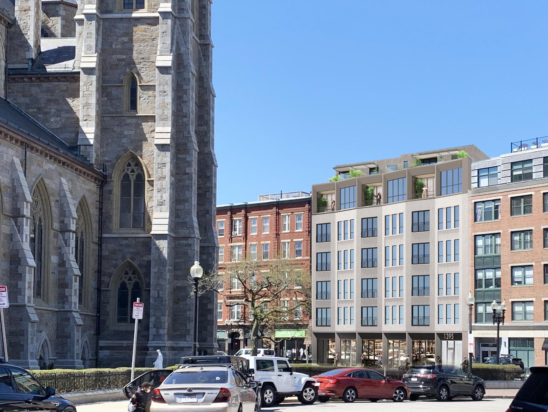
1395 Washington is going to be a 7 story multifamily building in the South End neighbourhood of Boston. Located along Washington Street, across from the Cathedral of the Holy Cross, the project will offer approximately 50 residential units. The building is situated between two existing structures, creating an interesting and unique design opportunity.
1395 WASHINGTON
Firm: Embarc Design
Client: Georgantas
Type of Project: Residential
Location: Boston, MA, USA
Role: Designer
Technical Skills: 1395 Washington is an exciting project with a very eager client. With much of their interest focused on unit design it was my responsibility and primary focus to design each unit carefully and deliberately for a quick review process. Due to the location of this project, I was heavily involved in the public process and historic landmark commission discussions during the earlier design phases.
32
Below is an example of the Unit Layouts I presented to the client that have since been approved. The site features a stark contrast where the front units are luxury and face the Cathedral, and the rear units will be “afforable” and face into an alley. I created multiple options of these units and refined them down to meet the clients goals.
08.03.21 1395-1405 WASHINGTON GEORGANTAS A16
UP UP DN DN W/D W/D W/D W/D W/D W/D W/D 925 SF 1 BD+ UNIT 205 1000 SF 1 BD+ UNIT 206 1030 SF 1 BD+ UNIT 207 MECH DW MECH DW MECH DW MECH DW 600 SF STUDIO UNIT 204 665 SF STUDIO UNIT 203 670 SF STUDIO UNIT 202 500 SF STUDIO UNIT 201 MECH MECH MECH DW DW DW UTILITY copyright: EMBARC Studio, LLC. 0' 4' 8' 16' C:\Local Revit\1395 Wash_Central-v2019_CUribeLJSLH.rvt 1/8" = 1'-0" 1395-1405 WASH NGTON ST BOSTON, MA A1020 SECOND FLOOR PLAN UP UP W/D W/D W/D W/D W/D W/D W/D 925 SF 1 BD+ UNIT 305 1000 SF 1 BD+ UNIT 306 1030 SF 1 BD+ UNIT 307 4' 6" MECH DW MECH DW MECH DW MECH DW MECH MECH 600 SF STUDIO UNIT 304 665 SF STUDIO UNIT 303 670 SF STUDIO UNIT 302 500 SF STUDIO UNIT 301 DW DW DW MECH UTILITY copyright: EMBARC Studio, LLC. 0' 4' 8' 16' C:\Local Revit\1395 Wash_Central-v2019_CUribeLJSLH.rvt 1/8" = 1'-0" 1395-1405 WASH NGTON ST BOSTON, MA A1030 THIRD FLOOR PLAN
FLOOR 2 FLOOR 3
1395 WASHINGTON 33
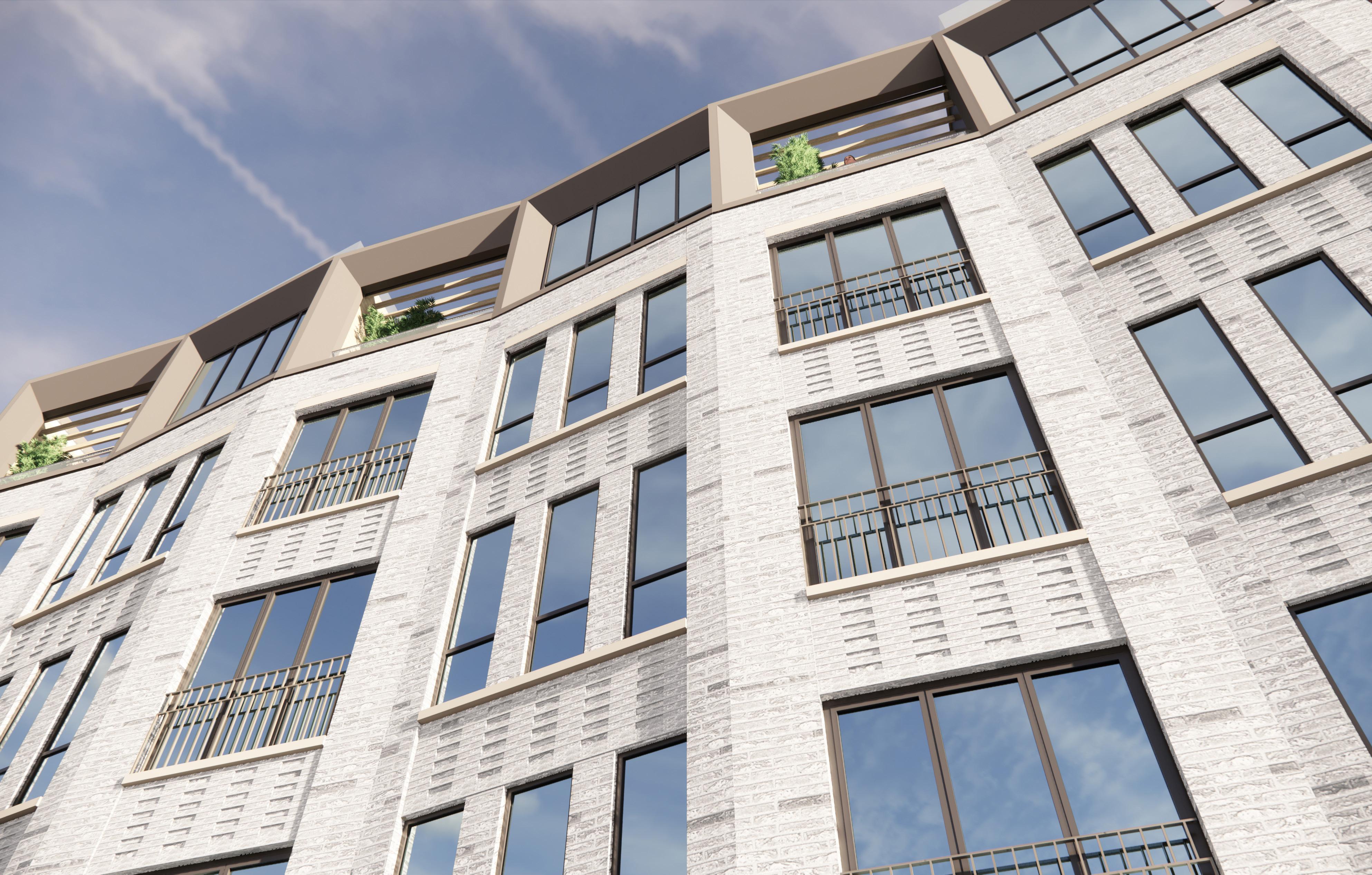
The facade of this building required a lot of attention and focus. We proposed grey brick to balance the materiality from the Cathedral across the street.We managed to get the client, as well as the BPDA on board.
PROFESSIONAL PRACTICE 34
WASHINGTON STREET
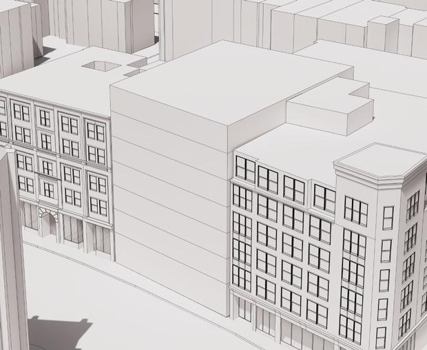
1
EXTRUDED MASS EXTENDING TO PROPERTY LINE OF STREET
WASHINGTON STREET WASHINGTON STREET WASHINGTON STREET
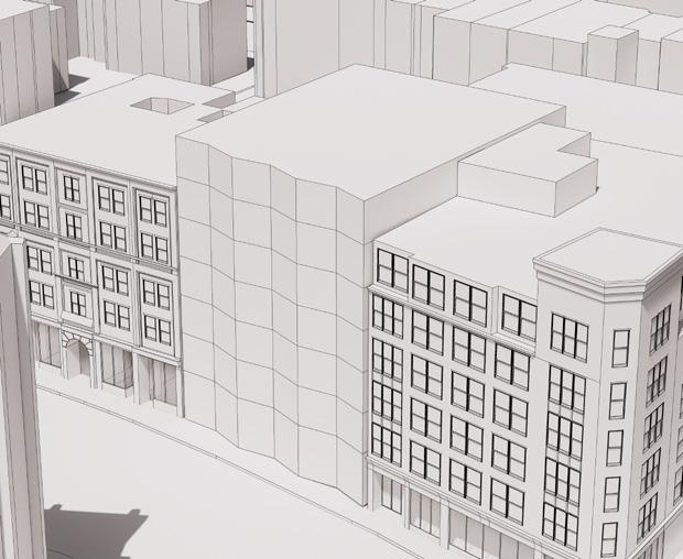
FACADE FOLDS TO BREAK UP FRONT AND EXPAND PEDESTRIAN REALM
2 MASSING DIAGRAMS
Our massing study was driven by the site constraints, as well as the surrounding architectural styles. We proposed a series of folds that would not only expand the narrow sidewalk, but also provide more opportunities for window design and brick detailing.
3
FACADE STEPS BACK TO ADDRESS CONTEXT AND SCALE
4
ARTICULATED FRONT CREATES TRIPARTITE DESIGN AND TIES INTO CONTEXT
09.22.21 1395-1405 WASHINGTON GEORGANTAS A9
1395 WASHINGTON 35
BOSTON ARCHITECTURAL COLLEGE
AUGUST 2018 - DECEMBER 2021

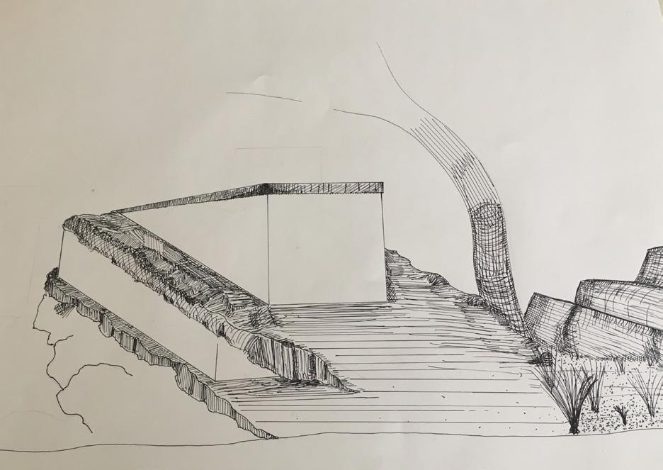
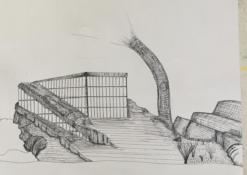
CAMBRIDGE COMMUNITY RECREATION CENTER

Studio IV at the BAC challenged us to progress from conceptual design to producing a true and realistic structure by identifying zoning and code constraints, construction and assembly types appropriate for the building proposal. A large emphasis was placed on structural and mechanical systems selection, as well as material construction.
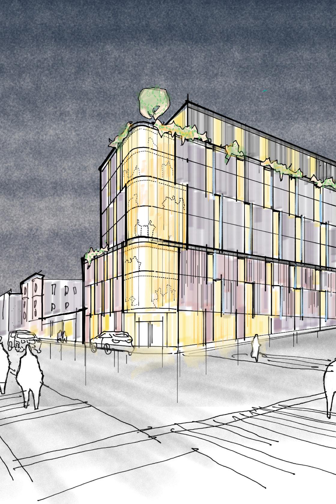
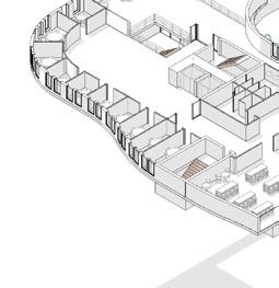
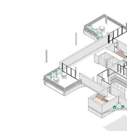
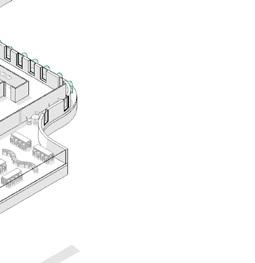
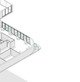
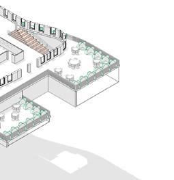
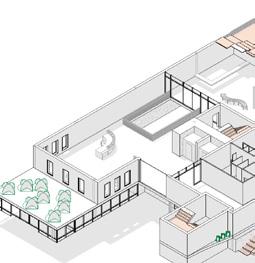
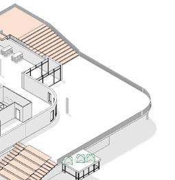
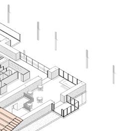
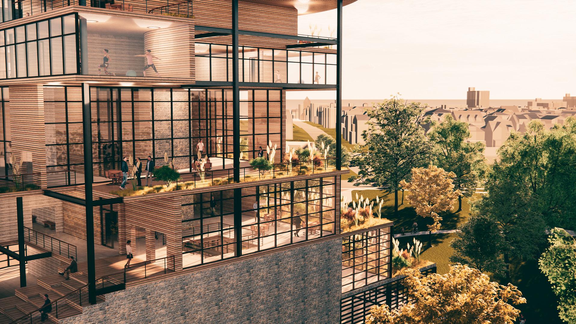
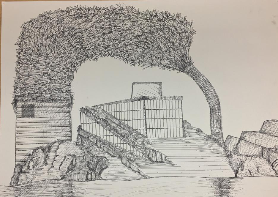
The Cambridge Community Recreation Center established a beacon using the concept of tree growth as the design driver. When a tree grows a new branch, it is taking an opportunity to create more life through an extension of itself. The Cambridge Community Recreation Center is following this mechanism by branching out its limbs to create small pockets of life suspended in the air. In these moments, the architecture intends to frame views, offer moments of relief, and create a warm environment for the user. Acting as a beacon from the exterior, the interior acts as a hideaway from the stresses of everyday life.
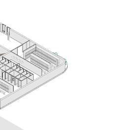
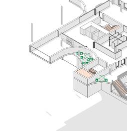
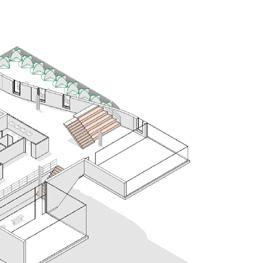
Due to the limited size of the property, I decided to program my building vertically. This allows for small pockets of activity to project from the core and giving each program their own specific nodes to exist.


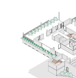
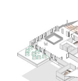


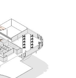


 Spin Studio
Social Hub
Squash Courts
Yoga Studios and Garden Terrace
Locker Rooms
Art Studios
Education Center
Spin Studio
Social Hub
Squash Courts
Yoga Studios and Garden Terrace
Locker Rooms
Art Studios
Education Center
37
Pedestrian Realm
The fourth floor terrace will offer tremendous natural light facing duesouth. This moment is an integration of interior and exterior activities.
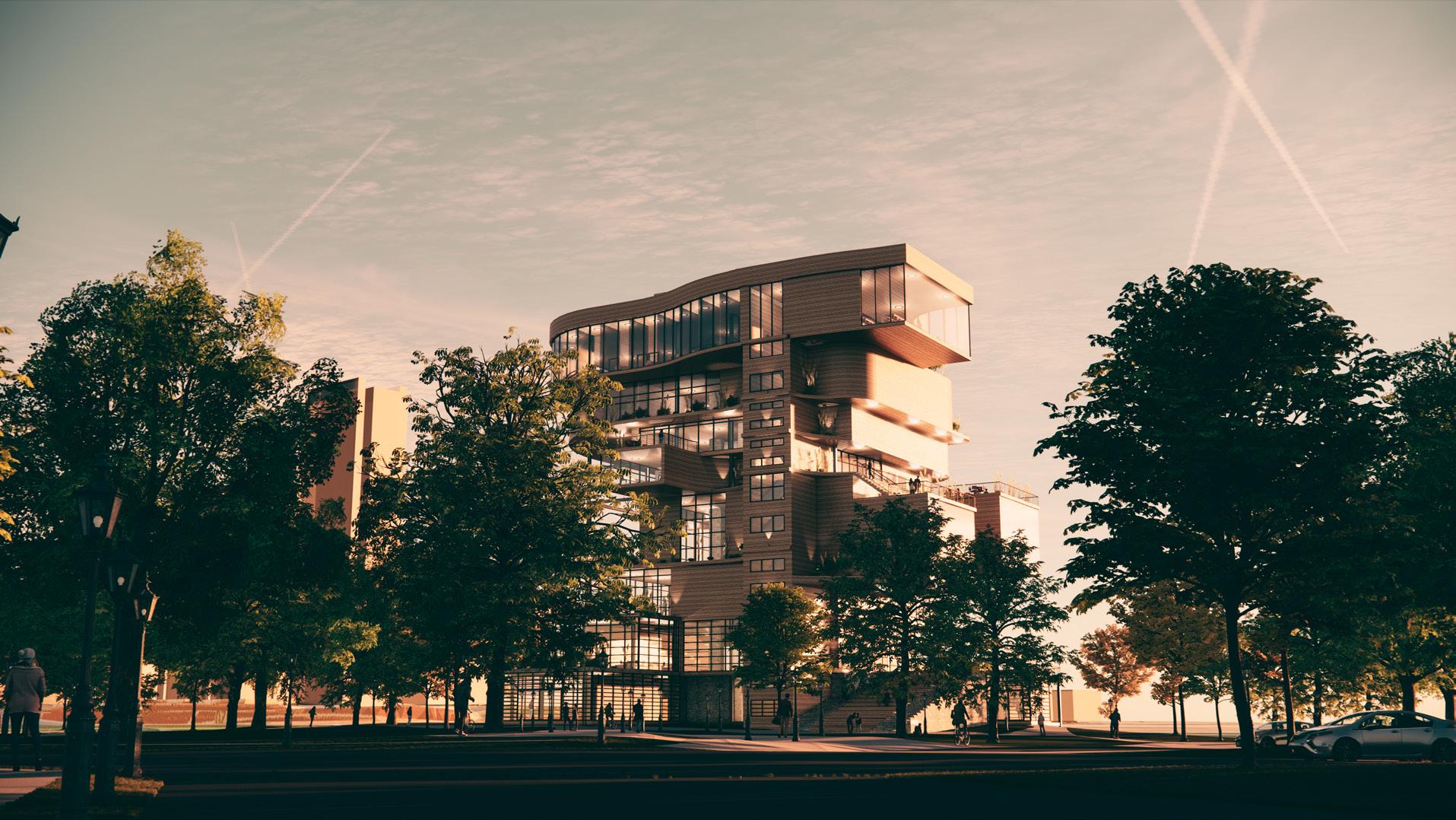
As seen from Magazine Street, this community center will act as a beacon for the entire neighborhood.
38
39
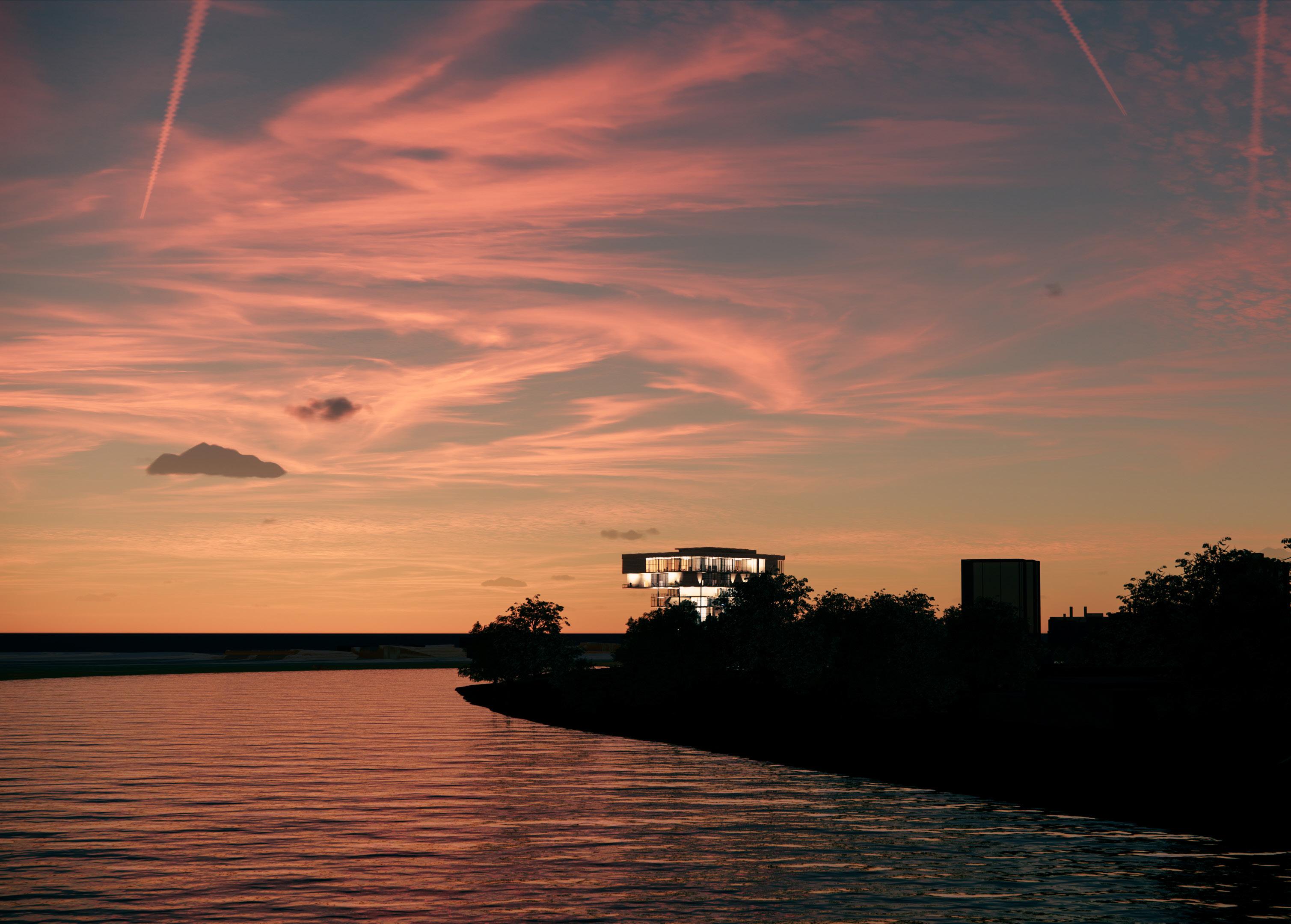
View from the Boston University Bridge
40
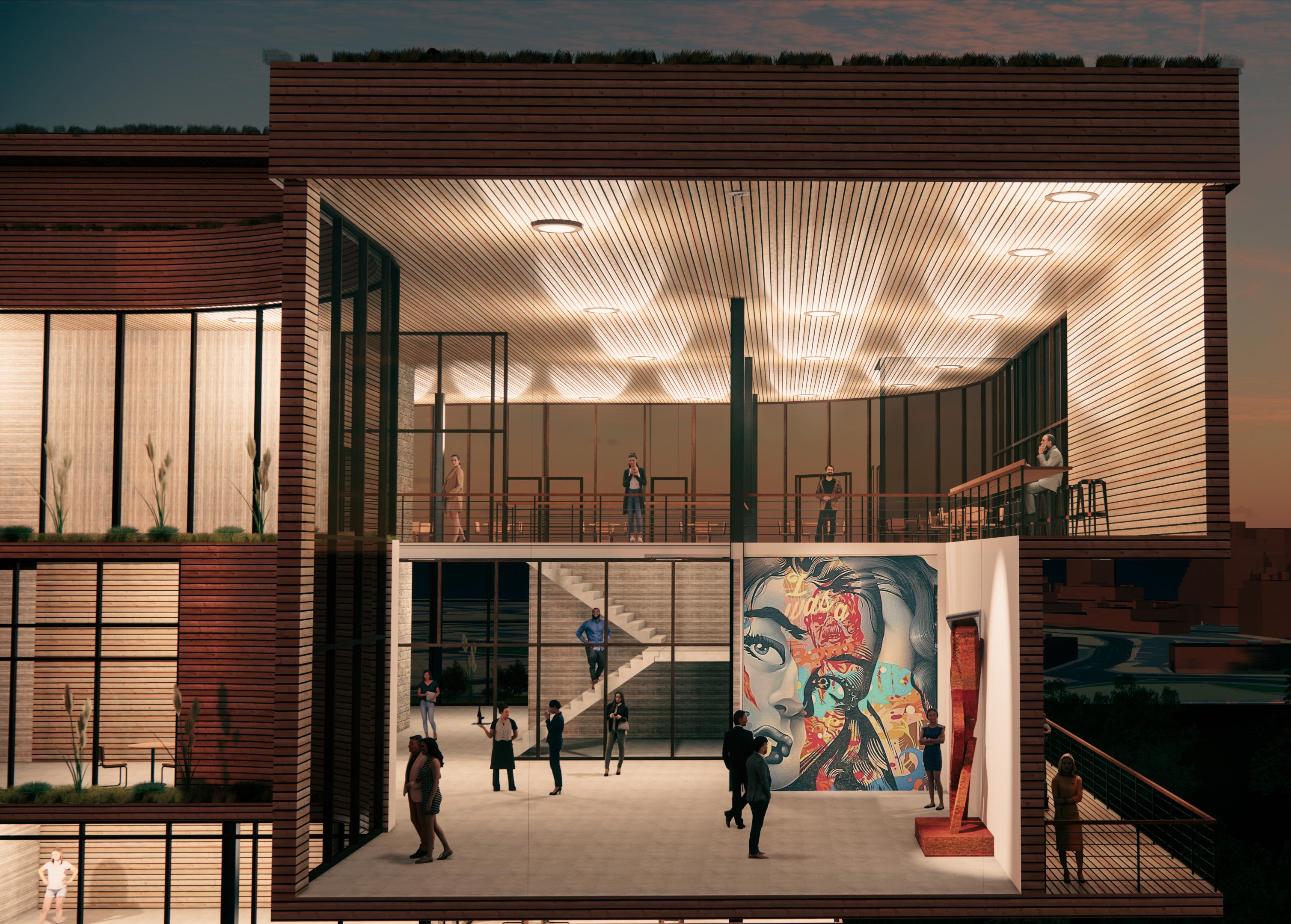
Birds Eye View of Top Floor Community Art Gallery


The building is constructed of a simple steel & concrete structure. This allowed for the most freedom when making decisions on the form and flow of the structure. Thanks in large to the small footprint of the building, a fairly small amount of columns are actually carried all the way to the roof level.
Steel Deck
Slab
Insulation
Beam
Concrete
Rigid
Steel
Wood Soffit & Cladding system
41
THANK YOU
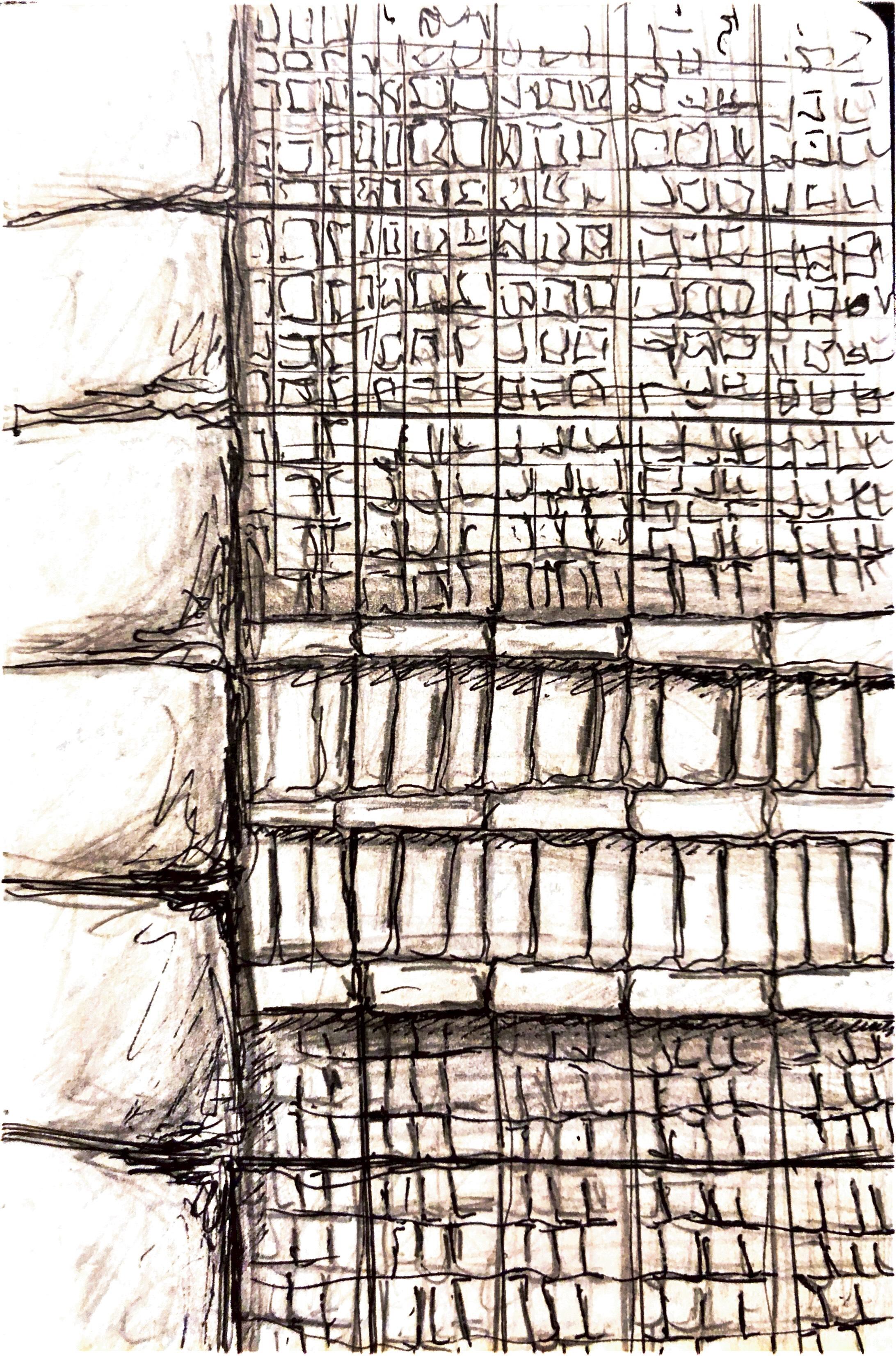
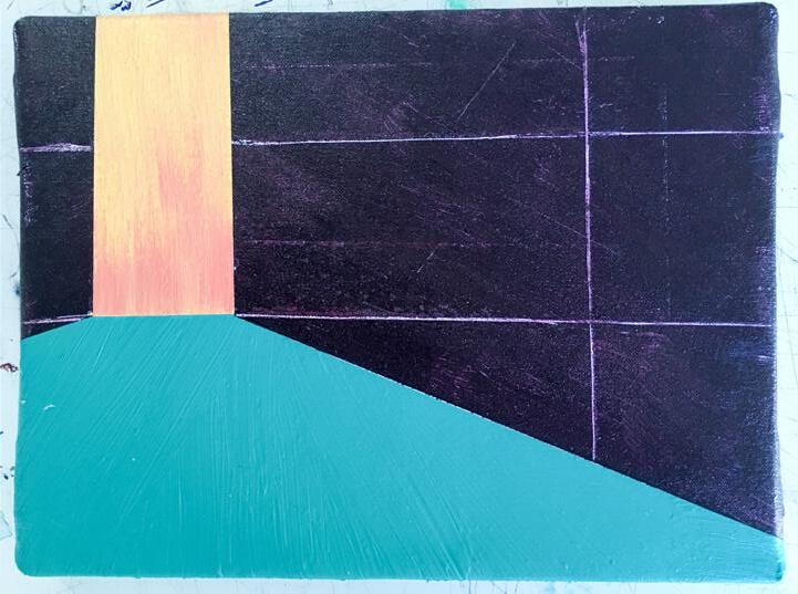
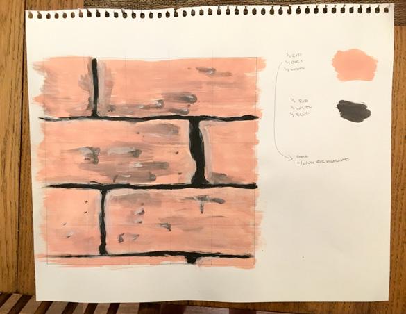
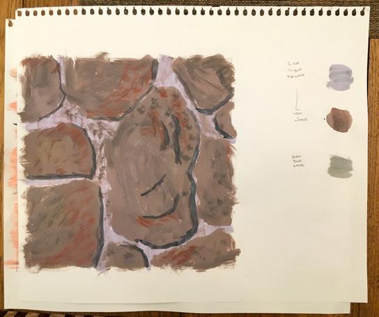
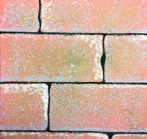
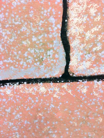
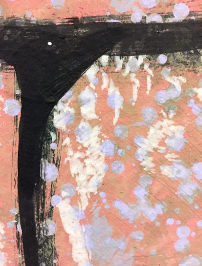
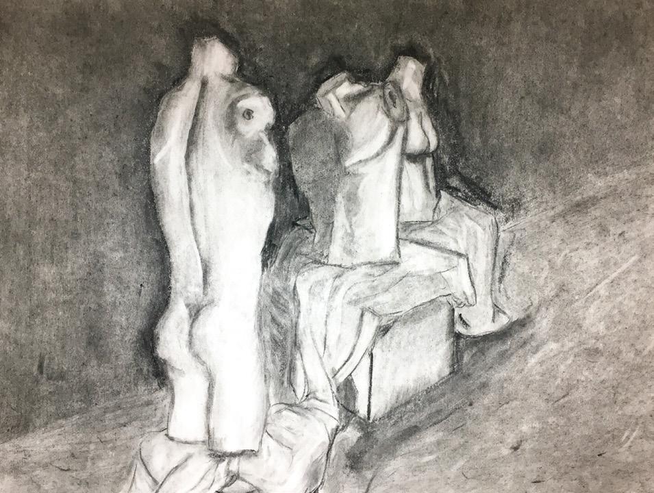
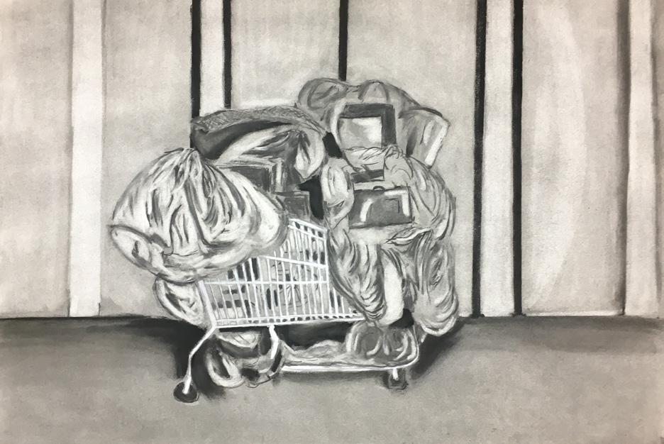
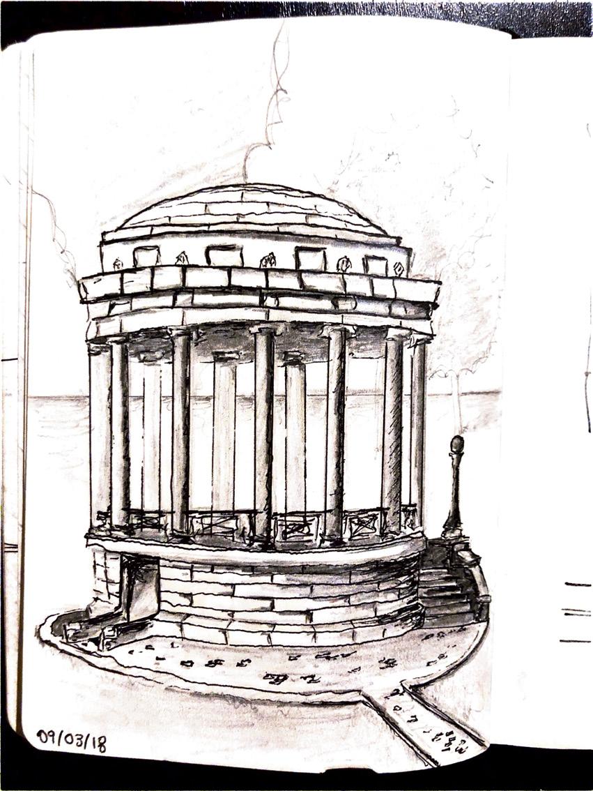
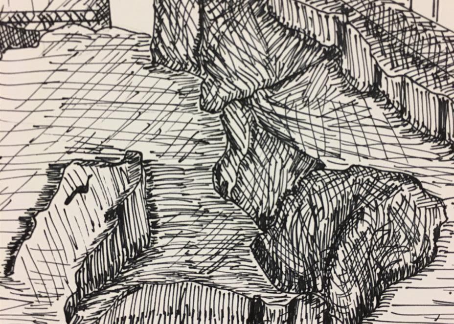
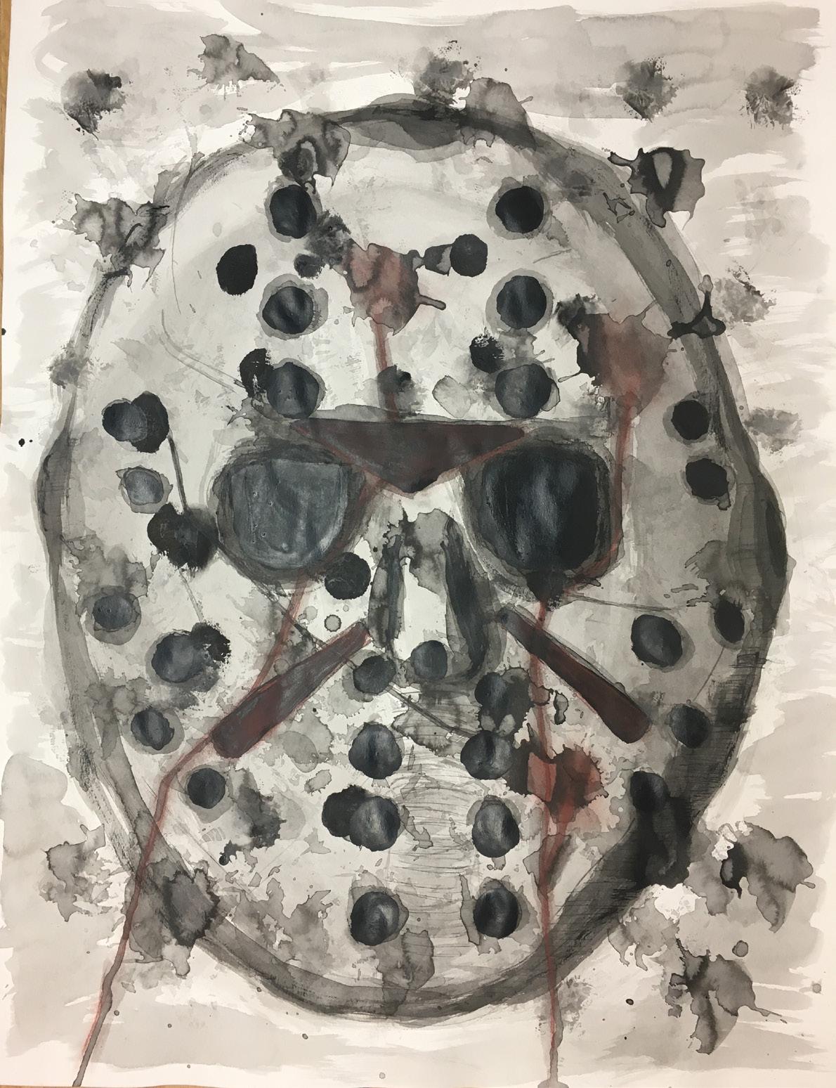
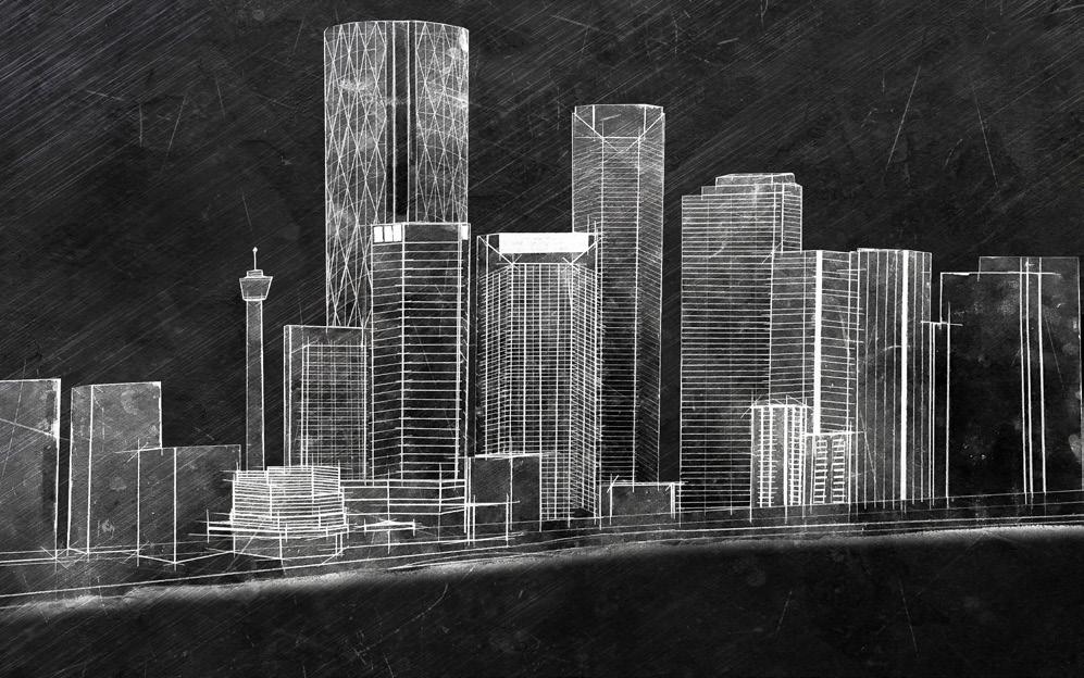
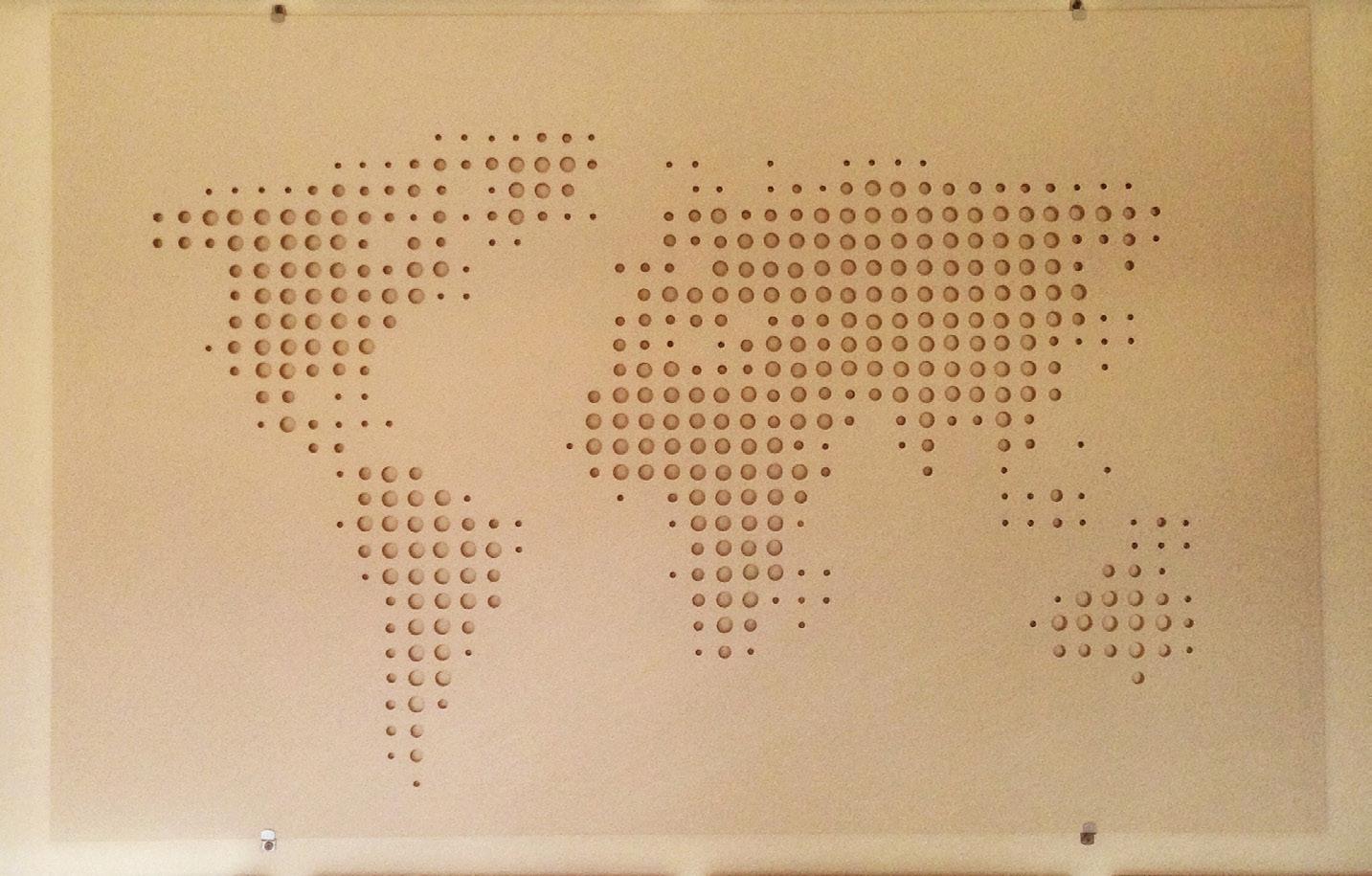
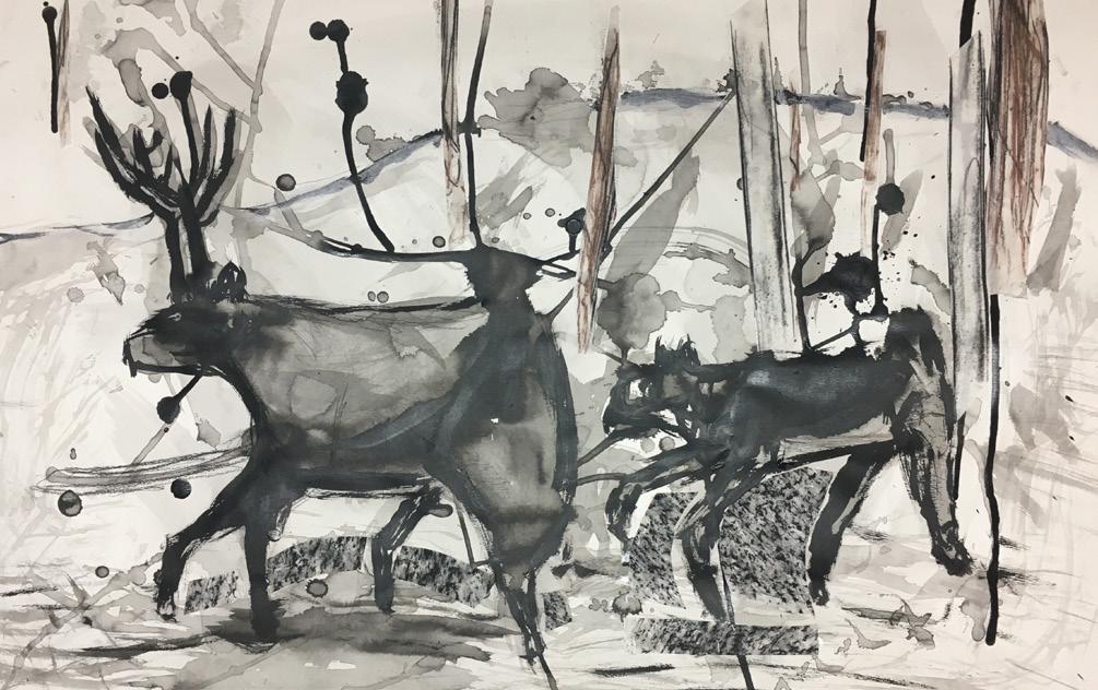
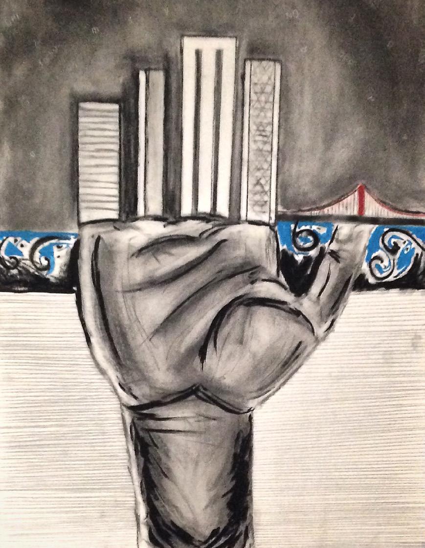
SELECTED ARTWORK
Throughout the course of my education, I’ve had the opportunity to mix the technical side of architecture while exploring its artistic side. Enrolling in art studios during my Bachelor’s Degree, I was able to explore many mediums including paint, ink, charcoal, and print. Many of these courses laid the foundation to my creative development as a professional, and allowed me to look at myself in a different light. The following page is a sample of my many works.
44
Brick detail of the Bruce C. Bolling Municipal Building


45

46

47