19 minute read
The History of Underwater Wet-Mateable Connectors
THE HISTORY OF UNDERWATER WET-MATEABLE CONNECTORS FROM THE INVENTOR’S POINT OF VIEW
Dr. Jim Cairns
Advertisement
I came to this industry in the 1960s and in the intervening 60 years I’ve been intimately involved with these products, first as a user, and then later as an inventor, and even later as a manufacturer. So, I’d like to tell the story of their history from the point of view of someone who has invented some of this technology. I’d like you to experience how hard it is to introduce new technology into an industry, and the roller coaster ride that sometimes takes the inventor through low periods of abysmally disappointing failure and other times through euphoric high points of success.
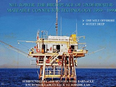
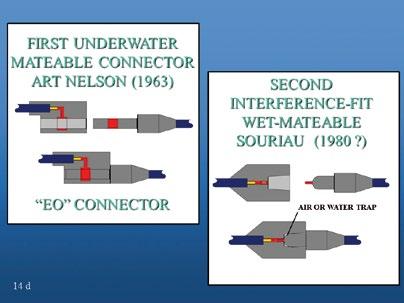
searchers at Scripps Institution of Oceanography. In the tower’s heyday a man named Arthur Nelson had re sponsibility for its operations and had the chore of keeping all those sensors working: replacing them, setting up new ex periments, knocking down experiments, and so on. During his time there he came up with the World’s very first – to my knowledge – underwater mateable electrical connector. It was of a sort called “interference-fit” connectors. The below sketches don’t necessarily represent exactly what these connectors look like today, but they show the essential ingredients of two types of existing interferenceof Art’s 1963 connector. The grey areas represent elasto mers, such as rubber. In the upper left panel the receptacle
Courtesy of U.S. Navy
The Navy Electronics Laboratory (NEL) offshore tower was built in 1959 for the Naval Electronics Laboratory (now SPAWAR), which is in the Point Loma area of San Diego, California. I refer to the tower as the birthplace of under water mateable connector technology. It was built one mile offshore of the San Diego community of Mission Beach, in water 60 ft deep, which is a nice depth for a research tower particularly because it’s an easy diving depth. You could make 2 or 3 dives a day there on compressed air… short dives, but without worrying much about decompression. The tower in its early years was a beehive of activity. It was surrounded by upwards of 100 sensors, most of them at tached to cables that went from the platform seen in the figure, down the tower legs, and maybe 200 or 300 hun subsea buoys in vertical arrays. It was used as a research platform by the scientists at NEL and very often by the re
fit connectors. The panel on the left shows a schematic dred feet away from the tower, and thence upward to
Courtesy of Jim Cairns

unit is cut-away in half, so that you can see a lighter shade bore that goes through it. The red portions are electrical contacts. The plug connector on the receptacle’s right has an elongated shaft with an electrical contact somewhere along its length. When the connectors mate, the plug shaft goes into the bore of the receptacle. It’s slightly larger than the bore of the receptacle so it makes an interference fit with the receptacle’s rubber bore. The schematic just above the “EO” CONNECTOR label shows the connector mated.
The schematic on the right illustrates the second type of interference-fit underwater connector. This one was first produced by the French company Souriau about a decade or two after Art introduced his. Here again, in the Souriau connector schematic, the grey areas represent an elasto mer. In the plug unit on the right you can see a red contact. Another red contact is at the base of a tapered recess into the face of the receptacle. The plug has a rubber base around its pin with a conductor sticking out the end. When the Souriau connector is mated, the plug pin goes into the tapered bore. The water or air it displaces is forced out back past it, and when fully mated the interference fit between the tapered bore and the fat base on the plug pin form an interference-fit seal.
The EO and Souriau designs are, to my knowledge, the only two sorts of interference-fit wet-mateable connectors on the market. Both are now made by several suppliers.
These interference-fit connectors are excellent products when used correctly in the proper environment. But they are not good for every operation and every environment. For instance, if mated in water that has a lot of suspended sand and silt, that material gets pulled in and interferes with the seal, possibly allowing electrical leak paths out to the saltwater surrounding the connectors. That’s one dis advantage, and operators must be careful where these are used. Another disadvantage is that they often do not come apart under high pressure.
When Art Nelson started Electrical Oceanics to produce what are now called “EO” connectors, he left the U.S. Navy lab and quit his work on the tower. The man who took over many of his responsibilities there was me. And so, I also had a lot of responsibilities for keeping the sensor arrays working. When Art was still on the tower, he connectorized many of the sensors, but his early connectors were as much of a problem as were the breakdowns of other sorts.
As I worked on the tower, I thought that there must be a bet ter way to make electrical connections underwater. I had the not-very-profound realization that the real problem was try ing to mate these electrical contacts in corrosive and conductive seawater. That’s always going create problems of one sort or another, unless you’re very lucky. The idea that came out of that thought process was to not make the connections in seawater at all, but to make them in a benign fluid bath (nonconductive), and to keep that bath sealed from the outside
Courtesy of Jim Cairns
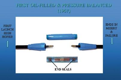
environment. From that thinking I proceeded to design what I think is the first of the second kind of wet-mateable connec tors: the “fluid-filled, pressure-balanced” kind.
As illustrated in the above figure, the designed connector consisted of three parts: The upper cylindrical portion was a capsule, and the lower two portions were electrical plugs. The plug pins had pointed conductive tips and insulated shafts. The lower panel is an axial cutaway of the capsule showing a central barrier that blocked the two halves (left and right hand portions) of the capsule from each other. The barrier seated back-to-back electrical receptacle con tacts, each in its own separate chamber. There was an endseal at the end of each chamber. The end-seals were tubular with outer diameters slightly larger than the capsule bore, and inner diameters very slightly smaller than the plug pins. The outboard surface of each tubular end-seal had a membrane over it. As the connector mated, each plug pin pierced the membrane of its respective end-seal and went on into a fluid-filled chamber wherein it mated to a recep tacle contact. To compensate for the fluid displaced by the entering plug pins, the end seals moved outward in the capsule. The end-seal movement also compensated for any volumetric thermal or pressure changes that might subse quently occur in the fluid.
This remarkably simple first connector had every ingredi ent that all subsequent fluid-filled pressure-balanced connectors have. It had penetrable end-seals which wiped the pins clean as they entered the fluid chamber where, sealed within a benign fluid from the outside environment, they mated to receptacle contacts. When I conceived of this in vention, I was working for the U.S. Navy as a civilian. I asked the NEL patent committee to patent on it on my behalf, and they did. They didn’t want any rights to it, so they assigned all the rights to me. As you can imagine, that was an ex citing moment of high hopes for a young inventor with his first patent. I took the patent and my rudimentary models to San Diego connector manufacturer Brantner & Associ ates, run by Bill Brantner. I asked Bill if he would take a licence for a year and see if he could make it and sell it, and he took it. Brantner & Associates invested money for injection and compression moulding tools, for plug pins and termi nations, manufactured the product shown in the previous

Courtesy of Jim Cairns
figure, and attempted to market it. However, at the end of one year my high hopes completely sank and misery fol lowed; nobody wanted to buy it. Bill gave up on it. When that failed, I decided to take another approach to the oilfilled pressure-balanced technology.
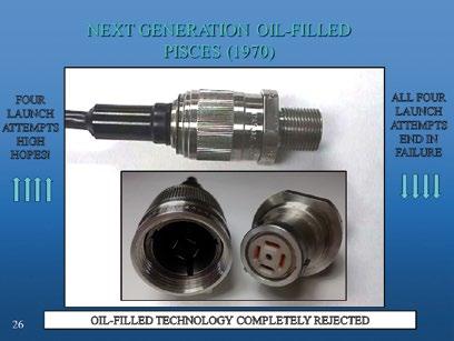
The above figure shows the next generation of oil-filled technology, I called it “Pisces.” If you look at the lower portion on the left, you can see the open face of the plug. It has four blade-like electrical contacts with insulated shafts and conductive tips. On the right, on the recepta cle’s face, there are four slit-like openings to accept the plug contacts, and there’s a central hole which went down into an elongated bladder within the fluid chamber. The bladder compensated the fluid pressure within the cham ber to the environmental pressure. The red material behind the receptacle face is an elastomeric seal with four slits to sealably accept the plug pins. This design followed my previous one by a few years.
Again, I went back to NEL and asked if they would file a pat ent on my behalf; this time they said no. They could see no interest whatsoever in connectors that could be mated and unmated underwater, so they gave me all rights to it. I went to my own attorney and patented it. Then, I again went to Bill Brantner and offered him a licence for the new prod uct. Bill took a one-year licence. A young engineer at the time, Pat Simar, whom many of you knew, finished up the designs and the company made nice prototypes, but after a year Bill was not able to do anything with it. Brantner & Associates turned out to be a hugely successful company, later becoming SEACON. Even back then they were a good company, but they didn’t have what it took that year to get the product on the market, so once again what started out with very high hopes ended in failure.
When Bill Brantner gave up his licence, I had his prototypes on my bookshelf at home and a good friend and neighbour of mine at the time, John Folvig, saw them. He offered to try to license the technology again. John was a graduate student completing his MBA, and I was a full-time graduate student at Scripps. John had a little bit more time than I did
Courtesy of Jim Cairns
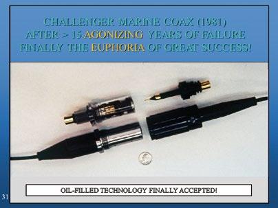
so he took on the licensing task. He quickly licensed it to Amphenol, a very prominent company, but their engineers wouldn’t do anything with it. That is something inventors run into from time to time when they go to a big company; their engineers just don’t want to fool around with an out side inventor, so after the end of the first year they gave up and we took the licence back. Flopped again!
John licensed it again to a third company that worked on it for another year, and they too gave it up; another dis appointing failure. The fourth and last licencing agreement was with Viking Industries. The very robust and reliable product that you see in the preceding figure was built by Viking. They put it through an immense number of qualify ing tests. It past them all, but then again at the end of the licencing agreement (now more than four years after the product was first licensed to Brantner) they couldn’t get anybody to buy it. We had gone through four periods of high excitement, each followed by dismal failure.
When I finished my graduate work I took a three-year re search contract with NATO at La Spezia, Italy and John went off to do other things. Three years in Italy changed my outlook on life. I loved doing research, but I really wanted to see if I could make a living as an inventor: a bold move for someone who had never yet sold a prod uct, but I did it. When I got back to the States I invented, for reasons I cannot explain, a coaxial wet-mateable con nector. The only reason I can think of why I might have done that, was that no such product existed in the world at the time, and I thought tapping into a different market segment might work. John Folvig and I decided to pool our funds and start a manufacturing company. We called it Challenger Marine, and we ran it out of half of a small building in a rural Florida town. We bought all the mould ing presses and everything we needed to start making connectors. When we were set up, and pretty much knew what that connector was going to look like, we made a hand-drawn sketch of it including specifications. We bought a magazine mailing list and sent it out. Sur prisingly, a couple weeks later we were getting calls from every major defence contractor in the United States.

Everybody wanted to know about our technology, and a short time later three gentlemen in dark suits from Lockheed showed up. They wanted to buy our technology and they also wanted to buy us. Their proposal was so tempting we couldn’t refuse. They offered to set us up in a proper manufacturing plant; they gave us all the engineering help, programme management support, quality assurance support, and everything we needed. A short time after we were in the new factory, we were able to build a coaxial connector that satisfied their programme requirements. What we didn’t know, until much later, was that there was a very important government programme that had been stuck for several years because there was no coaxial connector that would mate underwater, and ours fulfilled their requirements.
So, after more than 15 years of agonising failures and ups and downs we had the euphoria of a very great success. I can tell you from an inventor’s view, to see a problem, solve the problem, develop a product to fulfil the needs of that problem, and then to see it out in public use letting people do things that they could never do before; boy, that’s an eu phoric moment! To me it’s the greatest feeling in the world.
Anyhow, after Lockheed had successfully completed their der. When the connectors are mated, as you can see in gage in the fluid filled chambers, doubly sealed from the
government programme, they bought the company from us. It became Lockheed Challenger Marine. Once the gov ernment programme proved the high reliability of these fluid-filled connectors, offshore oil company engineers finally accepted them. And I would say in the decade fol lowing that they pretty much became the gold standard for subsea oil well completion systems. So, after many years of trying to introduce the fluid-filled wet-mateable connector Briefly I will explain how it works. On the upper right in the figure, you can see plug pins, the dielectric portions of which are blue. Three plug pins are visibible from this point of view; you can’t see the fourth. Each pin has a long insulated shaft with a conductive tip. On the lefthand upper portion you can see a receptacle with one circuit partially cut away. It houses a white piston and a spring. The spring is in an electrically conductive tube that goes back to the termination portion of the electri cal contact. The tube, having an electrical contact on its forward end, is contained in an individual fluid-filled bladder. Each circuit is like that, and those individual cir cuits are all contained within an overall fluid-filled bladthe bottom panel, each plug pin enters the receptacle end-seal and pushes its respective dielectric piston back against the spring. The pistons have been keeping the end-seals busy while unmated. As each pin enters, cor rigated elastomeric end-seals stretch and seal around it. The corrugations collect any contamination that might have been drawn in by the pins. The pins and sockets en
technology, it was finally accepted! outside environment.
Courtesy of Teledyne Marine
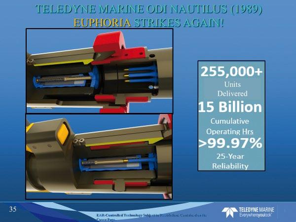
When we sold Challenger Marine to Lockheed, I moved back to Italy for a few more years. While there, I decided to try to design the most reliable, versatile, wet-mateable connector I could think of, without regard for cost. And the product I came up with was called Nautilus. When I patented this design, I went back to John Folvig and asked if he would join me once again – and he did – and in 1989 we formed Ocean Design, Inc.. Nautilus was our first product.
Courtesy of Teledyne Marine
Once again this was a huge success and of course John and I were very happy with that. Right now, over a quarter of a million of these units have been delivered with 15 billion hours of accummilating operating time and nearly 100% reliability. I would say that if there were some failures, they were probably in the early years when fastedious deck hands would rinse them off in kerosine before and after use… the elastomers didn’t like that very much .
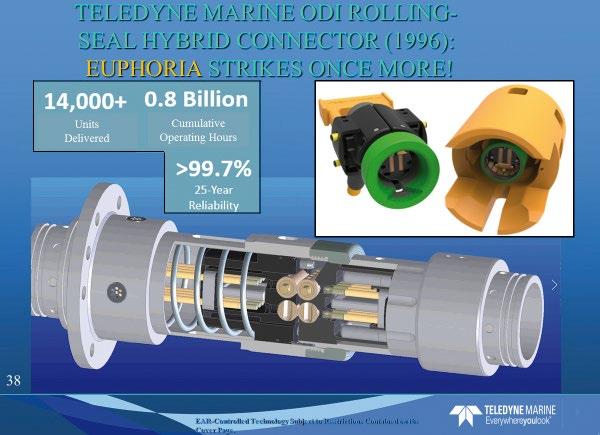
The last product I’m going to mention is Teledyne ODI’s Rolling Seal Connector. In the upper right-hand panel you can see two beige parallel lines in the faces of the connec tor’s plug and receptacle. These are the protruding faces of cylindrical end-seals. When the connectors come together, the plug and receptacle cylindrical end-seals press tightly against each other. In the lower panel, which is a cutaway, you can see in the opposed end-seals pressed together in the initial part of the mating sequence. You can maybe see
that in each of those cylindrical end-seals there are bores orthogonal to the long axis of the connector. Those bores are also filled with oil and are within the oil system of the plug and receptacle before mating takes place. As the con nector plug and receptacle mate, those opposed rolling seals are actuated to turn in opposite directions like the wringers of an old washing machine, so any material that’s been trapped in between them when they first come to gether is rolled sideways and out of the area where the connections are going to be made. Those through bores roll into alignment with the plug pins, then the pins proceed through them to penetrate the receptacle on the left.
You will see likenesses between this and the other wet-mate able connectors in that the plug pins have insulated shafts (beige in the figure) and conductive tips. In this case the tips can be electrical or optical, or any mix of those. You will also see one difference: the plug half of the connector is also oilfilled and has a flexible bladder (dark in the figure). That of course is very necessary for optical connectors because the optical contacts have to be kept immaculately clean. So, as the connectors mate this is the sequence: the rolling seals push together, the rolling seals roll, the through-bores ro tate into axial alignment, any material trapped between the rolling seals is moved off to the side, the plug pins go through those through bores and finally engage the recep tacle contacts in the receptacle’s fluid-filled chamber. Since 1997 there have been over 14,000 of these connectors delivered, with nearly a billion hours of cumulative operating time, and once again pretty darn close to a 100% reliability. This is another hugely versatile and reliable product.
I thank Teledyne for loaning these images to me. I have to say I have a great paternal attachment and pride in Tele dyne, and I’m very grateful to them for carrying this technology forward while continuing to keep up reliability and improving the versatility of the products.
Since 1997 there have been over 14,000 of these connectors deployed subsea, that’s nearly a billion hours of cumulative ABOUT DR. JAMES CAIRNS operating time, and once again pretty darn close to a 100% Jim is the father, the pioneering inventor, reliability. This is another hugely versatile and reliable product. of underwater wet-mateable connectors that have enabled so many vital subsea I thank Teledyne for loaning these images to me. I have to systems from cable observatories to say I have a great paternal attachment and pride in Tele tsunami early warning systems. He is a dyne, and I’m very grateful to them for carrying this tech physicist, oceanographer, and lifelong nology forward while continuing to keep up reliability and inventor with more than 60 issued and pending US patents. improving the versatility of the products. His most successful inventions have been components of subsea fibre optic and communications networks. He has cofounded two significant companies; the first: Challenger Marine he sold to
Lockheed Corporation in 1985, and the second: Daytona Beach based Ocean Design, Inc. (ODI) sold in 2009 to Teledyne. In 2003,
Jim started the Cairns Foundation, a charitable organisation supporting and encouraging innovation by creative students.





RM0053
RT0093
DISCOVERY THROUGH IMMERSION
We design and implement cable solutions from the surface to the seabed. • ROV and Deep Ocean Research • Ultra-deepwater applications • 6,000 plus metres • Trencher, Plough and Diamond
Mining Umbilicals • Steel wire armoured and Fibre braided strength members • Innovative and high strength armour packages • Electric stress and heat build-up analysis and testing UK: +44 (0) 1992 471 444 USA: +1 713 292 6486
www.fibron.com london@fibron.com
Fibron
