Saloni S. Shah|Architecture Portfolio | Selected works 17-24
HASTA - KALA PRAYOGSHALA
The Vault Institute
collage urban design, gift city
The Collage proposal
Semester 5, 6
Architectural working drawing set
Semester 7
Groupwork- Saloni, Miti D., Meet C., Vikrant B.
Udaipur
2019-20 Pg no. 4 to 11
GIFT City, Gandhinagar
2020-21
Pg no. 12 to 17
1 2
Construction drawings
Stone cladding details
Shaft door detail
H-block layout
Internship projects
VastuShilpa Consultants
Sangath Smritivan Earthquake memorial, Kutchch
2021
Pg no. 24 to 29 3
Pg no. 18 to 23
KBG house , Sanand Extension
Extension, renovation, furniture and landscape
First project - Vaissnavi
Shukl Architects
EXTRA WOrKS
Hands - on work skills
Kalhaar Blues and Greens, Sanand, Ahmedabad
2023-24
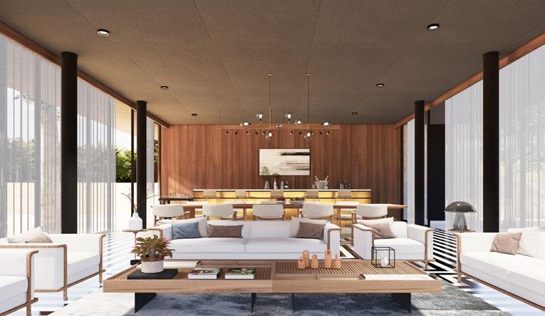
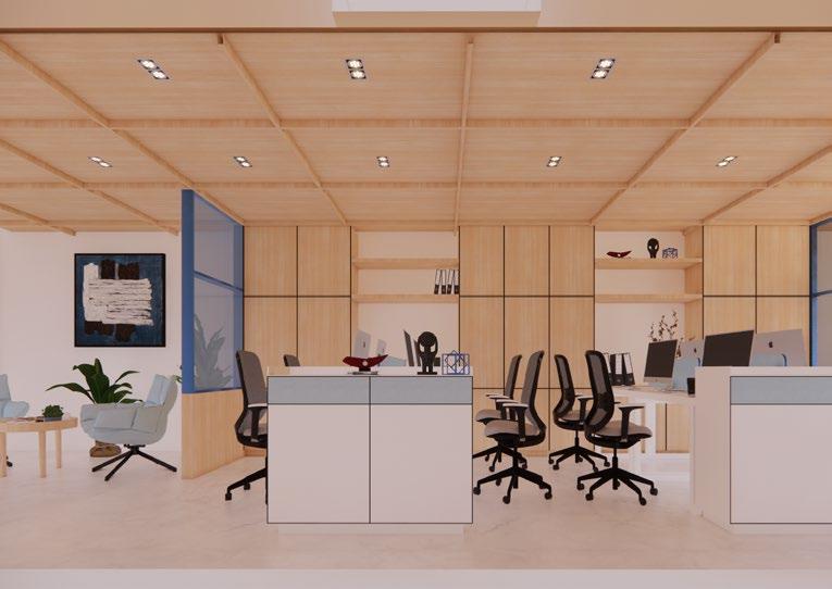
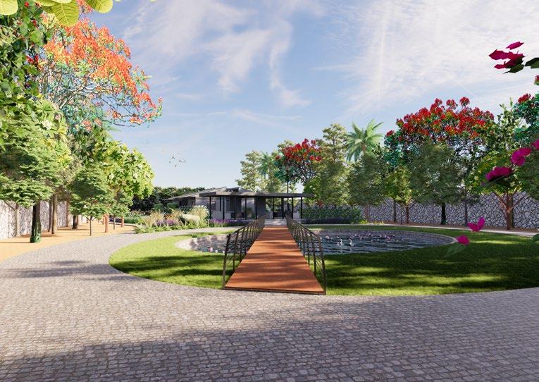
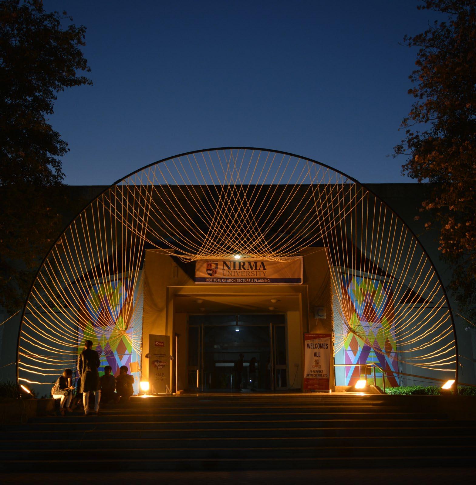
Workshops, model-making, sketching, interior design renders, office renders, art, installation
IAPNU, Ahmedabad
2018-24
Pg no. 30 to 32
5 4
index List
1. HASTA-KALA PRAYOGSHALA
Calm, serene, secular, repitition
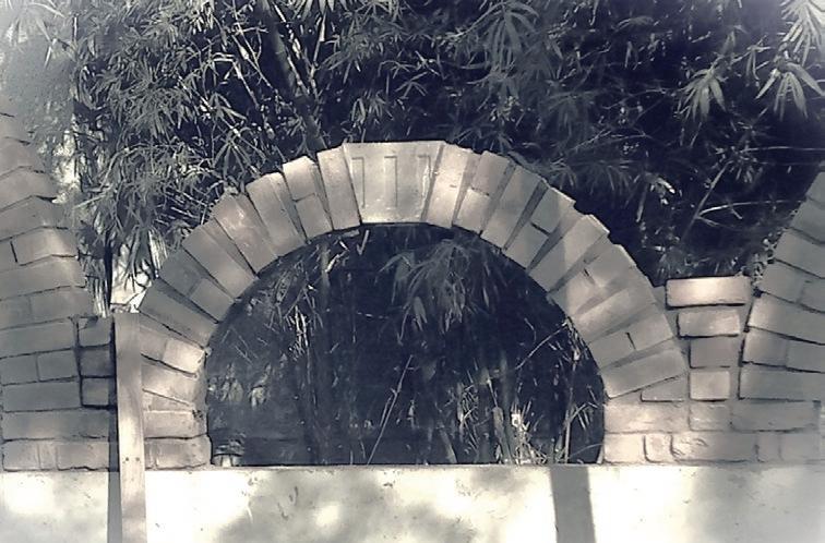
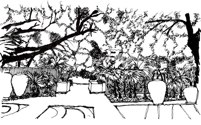
The National Institute of Design and Crafts, Udaipur is an extension of Indian poetry of culture; reinterpretation of its essence to a modern artifact. It is an attempt to bring life to the dying imprints of the indegenious craft forms by amalgamating them with modern utlity.
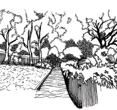
The contoured site within the limits of Shilpgram has many trees, a rural setting with celebrated backdrop of culture, and sparse vernacular house forms from yellow sandstone of Udaipur.
The drop of 5m provides a slope to work in split levels to create a spiritual journey to the ‘ashram’ where the Guru- Shishya Parampara emerges in the modern times. This understanding leads us to the
Site area : 11,290 m2
Ground Cover : 1860 m2
Carpet area : 1485 m2
concept of ‘interaction’ and inter-relationship, where student interaction spaces as well as secluded spaces are focussed. The program of 3 workshops, 4 kakshas, exhibition centre, several labs and library with admin and allied supportive functions are designed to target and cater 100 students and some visitors.
The concept of Layering and Depth is abstracted and a parallel wall language of architecture is generated and followed throughout the Institute. Individual student space for drafting, carving, modelling and painting the craft are provided with shared shaded spaces.
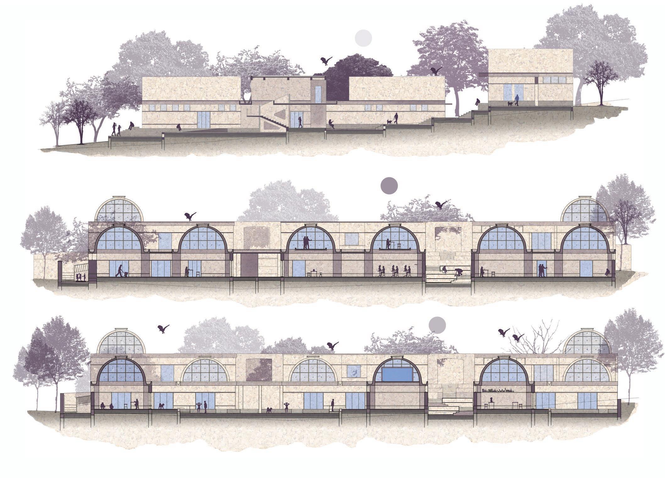
The stone masonary with RCC lintels and beams, dressed with china mosaic on vaults are specific to the roughness of program and context.

TOOLS TO ACQUIRE
AND COMPETENCE
EXPLORATION AND DESIGN THE SHALAS WILL INCLUDE OPEN AREAS WITH WET-DRY PREPARATIONS, FINISHING STORAGE AREAS.
1. DHAATU SHALA2. CHHAPAI SHALAPAINTING WORKSHOP
3. TEXTILE SHALA- TEXTILE WORKSHOP
SITE 2 : WITHIN SHILPGRAM -SHALA : IT WILL PROVIDE LEARNING SPACE AND HANDLING TOOLS TO ACQUIRE THE AND COMPETENCE IN MATERIAL EXPLORATION AND DESIGN THE SHALAS WILL INCLUDE OPEN AREAS WITH WET-DRY PREPARATIONS, FINISHING STORAGE AREAS.
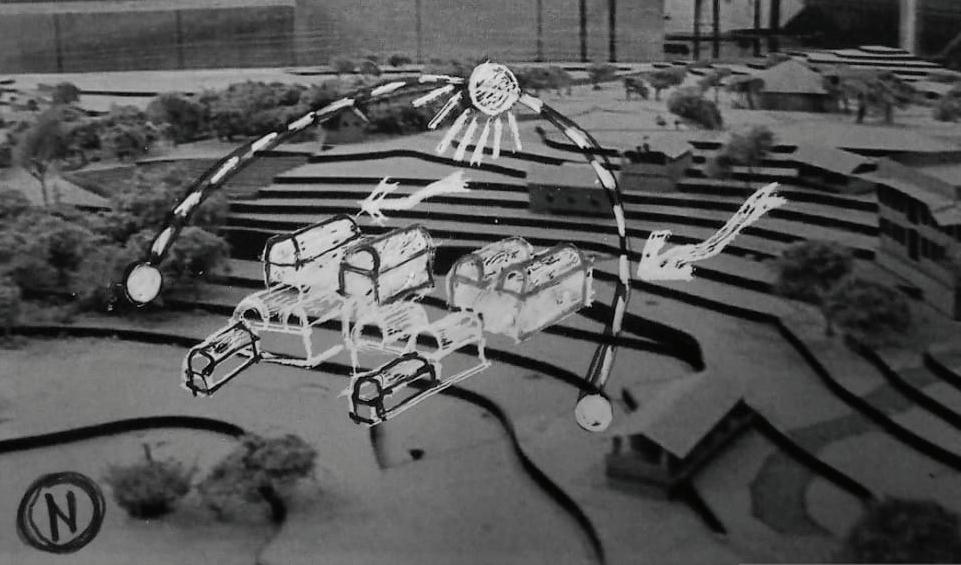
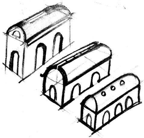
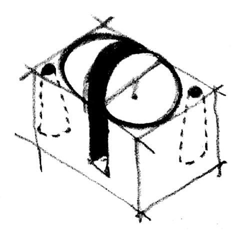
(Above): Sketch of the design on contextual site model
1. KUMBHAR SHALA TERRACOTA WORKSHOP
2. CHHAPAI SHALAPAINTING WORKSHOP
3. SHILP SHALA- STONE
EXISTING FACILITIES OF USED:
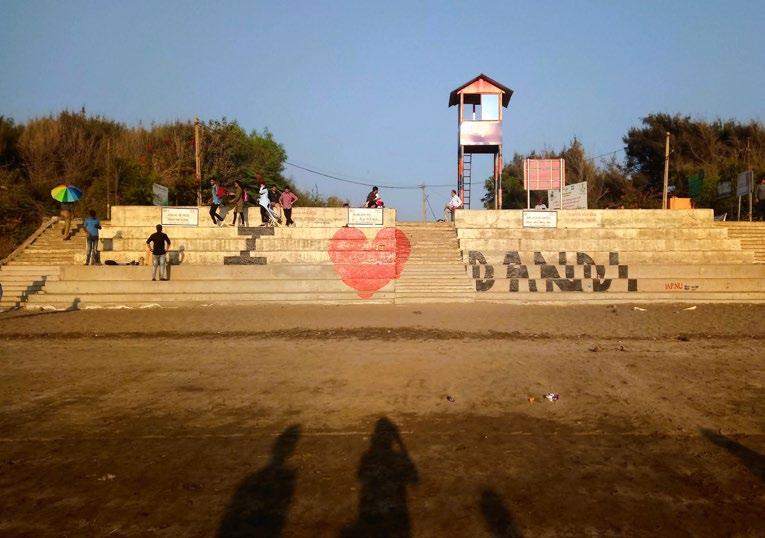
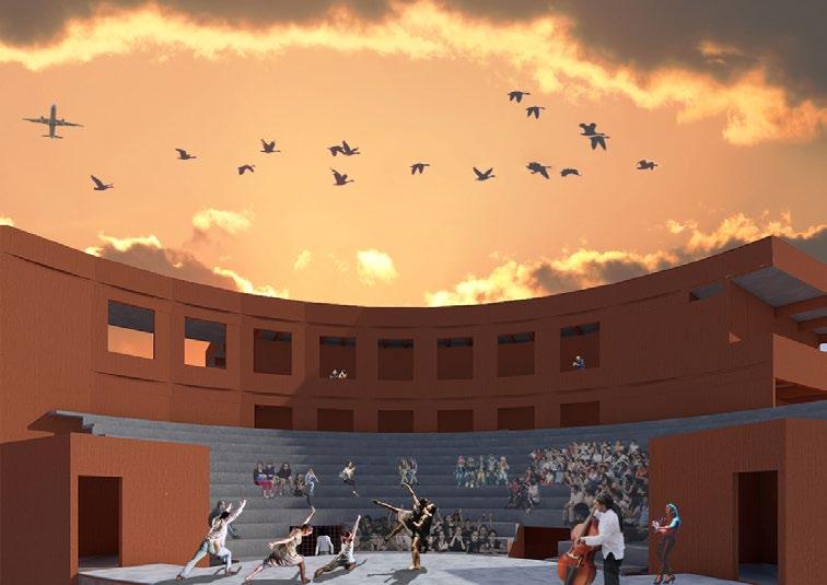
1. EXISTING AMPHITHEATRE
2. RESIDENTIAL UNITS 3. GUEST UNITS 4. FEW SHOPS
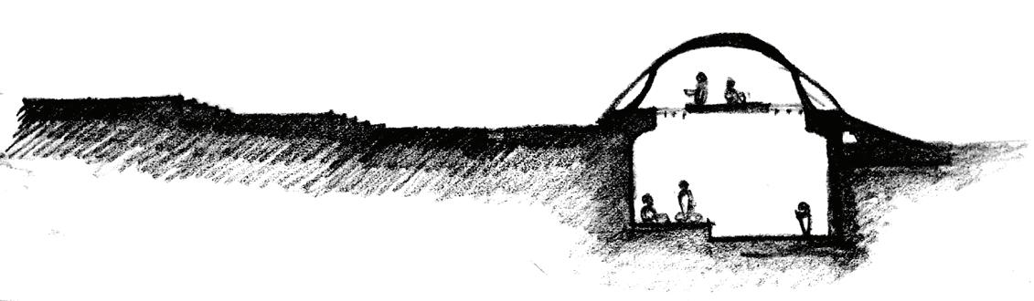
(Above): Series of process plans for student Kakshas (Below): Conceptual sketch section for student Kakshas
COMMON PROGRAMS FOR 1. LAB AND WORKSHOP INCLUDES COMPUTER PHOTOGRAPHY LAB LAB.
2. CRAFT DESIGN CENTREDESIGNATED FOR 3. KNOWLEDGE LIBRARY
NUMBER: 17 BAR
4. KAKSHAS- 4 STUDIOS INDIVIDUAL LEARNING LECTURE ROOM CONFERENCE ROOM ADMIN AREA
ADS INSTITUTE OF ARCHITECTURE NIRMA UNIVERSITY,2020
072
ANIL PROF. BHUSHAN PROF. PARITOSH PROF. GEETA LEGEND WINDOW TAG DOOR TAG FLOOR, WALL AND CEILING SCHEDULE UNFINISHED- FINISHED LVL WALL SECTIONS SECTIONS GRIDLINE DEMARCATION DIMENTION STYLE ROOM NAME, AREA DIMENTAND SLAB BOTTOM LVL AND DOWN DEMARCATION DIMENSION STYLE 1 2 3 CONCRETE KOTASTONE SAND BEDDING MORTAR CHINA MOSAIC CONCRETE IN PLAN WOOD ALUMINIUM BRICK MASONRY OVERHEAD BEAM OVERHANG SUNK SLAB LINTEL/SLAB @+ 3230 SYMBOL LEGEND SYMBOL LEGEND RCC ELEVATION01 RCC ELEVATION02 RCC ELEVATION03
STUDENT NAME: SALONI S. ROLL
FACULTY: PROF.
IN MATERIAL
THE
0 1000 6000 OTS A202 AA' RAMP 12 SLOPE A202 EE' A202 GG' D1 A A 702 KAKSHAA IV 7410 X 12320 SQ M. W2 C1 P Q D1 A A 702 D1 A A 702 A 702 FF' 0m 1 m 2m 3 m 4 m A901 WS3 DISCOVER HOW SMALL YOU AND KAKSHAA 111 -1.3 M LVL 6125 X 14400 SQ M. KAKSHAA 111 +0.60 M LVL 6125 X 14400 SQ M. P1 534 5879 534 5879 6413 6413 13343 + 3.85 LVL ENTRY OF INSTITUTE UP UP PLANTER'S SPACE PLANTER'S SPACE UP 0.00 mm LVL COURTYARD UP UP RAMP 1:10 SLOPE + 0.0 M LVL + 3.85 LVL + 3.66 m LVL + 3.66 m LVL +2830 mm LVL 3505 mm LVL 3435 mm LVL +80 mm LVL +0.0 mm LVL +1225 mm LVL +1135 mm LVL +2365 mm LVL +2265 mm LVL +3400 mm
(Above) : Short section cut through student Kakshas
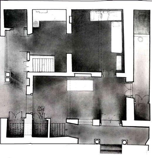
(Above): Working drawing plan of the Institute
“Meditation
UP FAB LAB 7110 X 9200 +0.0 M LVL PN. & PR. SHALA CERA. & TERA. SHAALA +0.0 M LVL 18850 X 9540 SQ M. KAKSHAA III + 0.0 M LVL 7410 X 12320 SQ M. PLINTH 0.00 M LVL ADMIN AREA 7110 X 15455 +0.0 M LVL 5510 3915 3490 3915 7525 7545 LECTURE ROOM 7075 X 7580 + 0.0 M LVL 10 A202 BB A202 BB' A202 CC' A202 AA' A202 CC UP UP PHOTO LAB 7105 X 7765 +0.0 M LVL A C D E F G J L 6.6 m 6.2 m 3.6 m 3.6 m 6.2 m UP UP 1 10 SLOPE 24 19 15 14 13 11 P1 P1 1350 G. WROOM +0.0m LVL 7300 X 7140 SQ M. 3.6 m B. WROOM +0.0m LVL 7300 X 7000 SQ M. 44055 76195 RAMP RAMP PLANTER'S SPACE PLANTER'S SPACE EE' A202 A202 GG' A202 HH' A202 HH' 2 4 7 1 6 3 5 9 8 10 18 17 15 14 16 12 360 13 20 19 1855 18850 3650 1825 6690 UP 18870 11 22 21 11 9 10 12 16 17 18 21 22 23 0.00 mm LVL 0.00 mm LVL mm LVL 0.00 mm LVL COURTYARD 1765 3180 3180 1590 1590 3180 3180 1590 20 3180 1775 3180 3180 3180 2 7 8 6 5 4 3 3180 1590 1590 1590 1590 4770 3180 1 3180 2780 2780 400 2780 400 2780 400 2780 2780 400 2780 400 400 1715 2700 7410 12320 2705 2350 2350 2350 1400 13220 400 890 14860 2780 400 400 2335 2700 3015 2700 3045 2705 2350 6115 1135 3090 1135 6135 1390 400 2780 400 2780 400 1390 1390 400 2780 400 2780 400 1390 9540 W2 F2 C1 W1 F1 C1 W3 F3 C1 W2 F2 C2 +0.0 M LVL 18850 X 9540 SQ M. 3.6 m W1 F1 C1 2335 2700 3015 2700 8120 1390 400 2780 400 1800 400 9540 960 6230 990 2720 500 2500 1275 2500 2425 2500 840 1800 6115 1135 3090 1135 6135 7975 4350 26530 1690 1390 5320 400 2830 2780 1165 7575 4570 400 2815 16345 8310 8310 7995 7765 9200 4780 1800 825 4370 400 2865 LIFT K D1 A A 702 D1 A A 702 D1 A A 702 D1 A A 702 D1 B A 702 D1 B A 702 6140 10185 50 mm LVL D1 A A 702 2110 7410 4350 2780 2780 4345 1800 2780 2500 7410 400 400 400 400 400 400 15455 2780 4345 7100 1800 2785 2700 3015 2700 11445 2785 2700 3015 2695 11450 2830 615 1250 2650 2200 2500 500 3330 D1 A A 702 1755 7075 8175 2105 B 450 225 225 225 7845 25 410 12320 2830 1750 360 2840 4345 400 2780 400 4370 400 2865 7105 490 3705 500 2500 1275 2500 2425 2500 825 A C D E F G J L B 2780 450 7075 465 400 400 1350 400 450 7410 450 450 7100 450 19770 3465 450 7400 450 4790 450 440 4350 2780 2780 4345 400 400 400 5320 2820 400 1380 1400 1565 450 400 2825 14320 320 2850 360 1690 D1 B A 702 515 D1 A A 702 D1 A A 702 1690 1:10 SLOPE 11370 900 1800 2635 1350 1085 3445 450 1360 6790 1390 400 2780 400 2780 400 1390 350 540 520 2335 2700 2375 450 4125 2105 450 620 6170 450 620 11445 1390 400 2780 400 2780 400 9540 1390 6510 400 400 400 350 400 2780 400 2780 400 1390 1400 9540 10425 350 400 2780 400 2780 400 1390 1400 10430 2635 1800 2640 4345 400 2780 2780 4345 400 19305 450 400 +65 mm LVL 0 mm LVL 2730 400 2780 4345 450 2755 2040 450 4475 2780 2780 400 2780 400 400 12320 2780 400 2780 400 400 2780 1390 1390 7870 630 450 530 530 H 5710 6510 1215 2780 2780 2780 400 400 400 400 12320 1165 1025 1560 1045 3625 3895 350 3010 2350 2960 450 535 1390 A202 JJ' A202 JJ' 3455 840 825 450 2965 450 D1 B A 702 8000 19795 1070 2500 500 3330 450 450 3890 7080 23 1350 400 400 D2 A A 702 D2 A A 702 D2 A A 702 D2 A A 702 2960 A202 FF' L' 1845 1360 D2 A A 702 D2 A A 702 -1.17 mm -1.17 mm 400 535 1390 UP 0 mm LVL +65 mm LVL 0 mm LVL 0 mm LVL +65 mm LVL 0 mm LVL 0 mm LVL +65 mm LVL 0 mm LVL 0 mm LVL +65 mm LVL 0 mm LVL +65 mm LVL 0 mm LVL +65 mm LVL 0 mm LVL UP PLANTER'S SPACE 6 m (-2m) -1 m 0 m 1 m 2 m 3 4 m -455 mm LVL -565 mm LVL +80 mm LVL +0.0 mm LVL +1225 mm LVL +1135 mm LVL +2365 mm LVL +2265 mm LVL +50 mm LVL +3400 mm LVL -1025 mm LVL -1135 mm LVL +2830 mm LVL 65 mm 0 mm 0 mm 565 mm +1700 mm 3400 mm 2830 mm -565 mm 3465 F' 2350 DN UP DUCT SHOWER A901 WS2 A901 WS1
is leaving yourself free from main silent and discover how small you
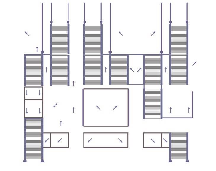
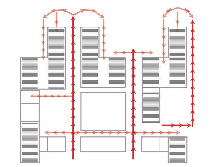
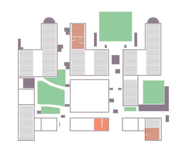
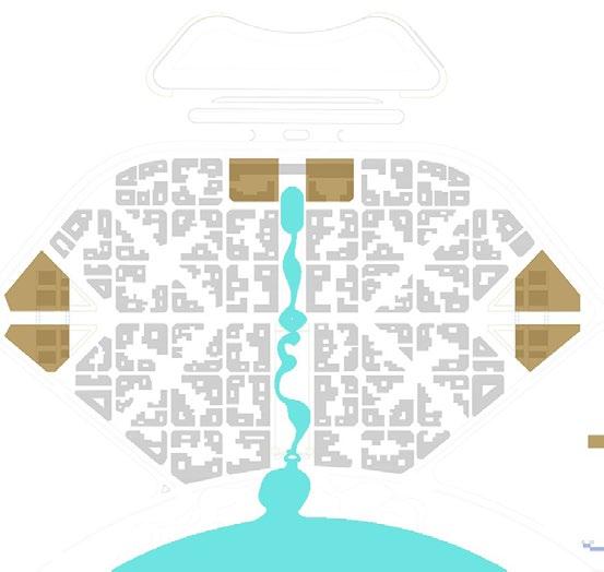
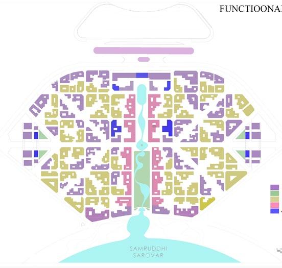
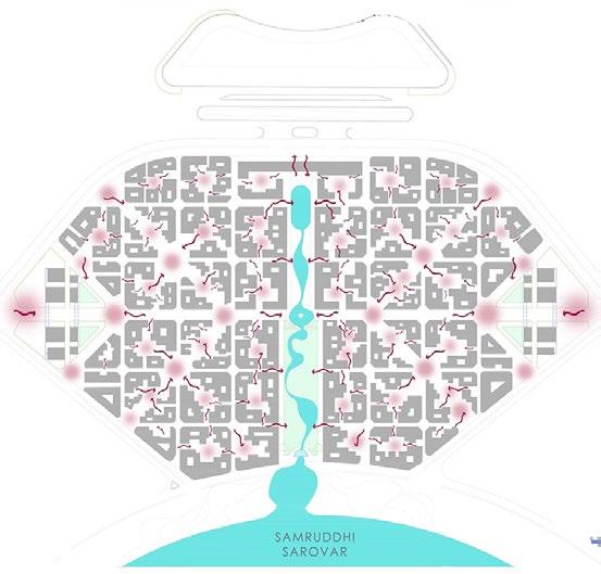
(Top) : Water channel, drain, spout diagram (Middle) : Circulation diagram within Institute (Bottom) : Services diagram- green lawns, orange wet services areas, purple vertical circulation
from
0 1000 6000 7795 3640 OTS 7345 890 A202 AA' M N P UP RAMP 12 SLOPE 14875 7860 STORE +0.0 M LVL 7355 X 3010 SQ M. 3.2 m A202 DD' DD' A202 A202 EE' A202 GG' STONE SHAALA +0.0 M LVL 18195 KAKSHA I +0.0 M LVL 7250 X 12320 SQ M. 6.2 m +0.100 m LVL 0.00 mm LVL -1.17 mm -565 mm LVL Q GROUND FLOOR PLAN Scale 1:100 3180 3180 3180 3180 1775 1755 3180 1855 1860 3180 1590 1590 3180 3180 3180 1590 3180 3180 1590 1590 1590 1590 4770 2780 400 2780 2780 400 2780 400 2780 400 2780 2780 400 2780 400 620 1990 620 7410 12720 2350 2705 2350 2350 2350 1400 18150 X 9540 SQ M. 6.2 m 18150 2335 2700 3015 2700 3045 2705 1695 1390 400 2780 400 400 1390 9540 W1 F1 C1 960 1215 350 1230 350 350 350 350 1255 1240 1240 1215 200 9540 3900 1800 2355 3900 1650 3010 1205 1835 3010 1205 1735 1215 2780 2780 2780 400 400 400 400 12320 5200 1800 5325 5550 1800 5325 P1 7250 D1 A A 702 D1 A A 702 D1 A A 702 D1 A A 702 P1 1845 KAKSHAA IV + 0.0 M LVL 7410 X 12320 SQ M. 6.2 m +65 mm LVL +0.0 mm LVL W2 F2 C1 1800 7355 D1 B A 702 1580 3400 1580 D1 B A 702 2710 6925 66010 2020 3400 1830 3245 3220 260 2700 3045 2700 2840 13700 11465 2785 2700 3015 2700 11450 1800 2700 235 235 D1 A A 702 GENERAL NOTES: THIS DRAWING AND DESIGN ARE THE SOLE PROPERTY OF ARCHITECT AND SHALL NOT BE TRACED, COPIED, LENT, REPRODUCED, MODIFIED OR MADE UNAUTHORISED USE IN ANY MANNER WITHOUT THE WRITTEN CONSENT. ALL THE DIMENSION ARE IN MM. ALL THE DIMENSIONS SHALL BE READ AND NOT SCALED. DIMENSIONS IN DRAWINGS TO A LARGE SCALE SHALL TAKE PRECEDENCE OVER THOSE TO A SMALLER SCALE. ALL THE DIMENSIONS ARE UNFINISHED DIMENSIONS UNLESS OTHERWISE MENTIONED. ALL AMBIGUITY SHALL BE BROUGHT TO THE NOTICE OF ARCHITECT IMMEDIATELY. KEY PLAN/ LOCATION: DRAWING : PLAN PLINTH + 1550 MM LVL SCALE: 1:100 SEMESTER: VI PROJECT INFORMATION NID # C, UDAIPUR STUDENT: SALONI S. SHAH ROLL NO.: 17 BAR 072 INSTITUTE OF ARCHITECTURE AND PLANNING, NIRMA UNIVERSITY 2020 HATCH LEGENDS CHECKED BY: DATE 9 06 .2020 WINDOW SCHEDULE RCC ELEMENT SLOPES OF GUTTER Finished level Unfinished level STONE WALLS A 101 W1 A HORI. PIVOT WINDOW W1 B HORI. PIVOT WINDOW 1. 9.01.2020 2. 29.01.2020 3. 12.02.2020 4. 27.02.2020 5. 13.03.2020 6. 27.03.2020 7. 4.04.2020 8. 18.04.2020 9. 29.04.2020 M N P Q D1 A A 702 D1 A A 702 900 6935 400 3245 3220 3530 2270 400 400 400 23950 400 11450 520 2335 2700 2375 450 3045 2700 4310 UP UP 1 10 SLOPE RAMP 400 400 225 D1 B A 702 515 1215 350 1230 350 350 350 350 1255 1240 1240 1215 9880 355 2780 400 2780 2780 400 2780 400 550 1390 2780 410 1390 550 735 DOOR SCHEDULE MARK D1 A 2700 x 2200 D1 B D2 A D2 B 1800 x 2200 1350 x 2200 1250 x 2200 RCC BEAM BOTTOM GRASS IN COURT 10. 15.05.2020 W2 A VAULT CURTAIN WALL C2 F3 800 x 1200 VITRIFIED TILES WASHROOM W1 15MM THK MALLA PLASTER C1 RCC VAULT WITH INTERIOR PLASTER 10MM F2 TERAZZO FINISH W2 15 MM THK PLASTER F1 WORKSHOP FLOOR FINISH W3 600 X 300 WALL TILES WASHROOM W2 F2 C1 1415 5120 3005 6705 1140 10335 ROOF OVERHANG SKYLIGHT ON VAULT FINISHES SCHEDULE W3 A 1900 SLIDING WINDOW 25355 1445 1545 12445 11500 A202 FF' 6.2 m HIGHEST CEILING HEIGHT +50 mm LVL +0.0 mm LVL +0.600 m LVL +0.560 m LVL +0.00 m LVL +0.00 m LVL 4310 D2 B A 702 W1 WINDOW ABOVE mm LVL 0 mm LVL 0 mm LVL +65 mm LVL 0 mm LVL +65 mm LVL mm LVL -1m 0m 1 m 2m 3 m 4 m A901 WS3
public, in your work where you reand your problems are in the world.”
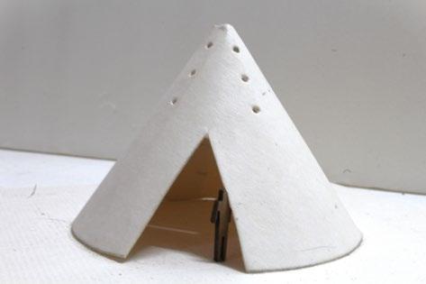
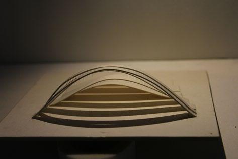
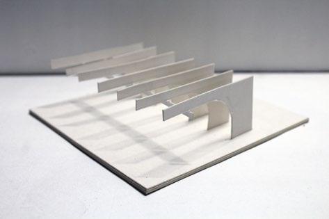
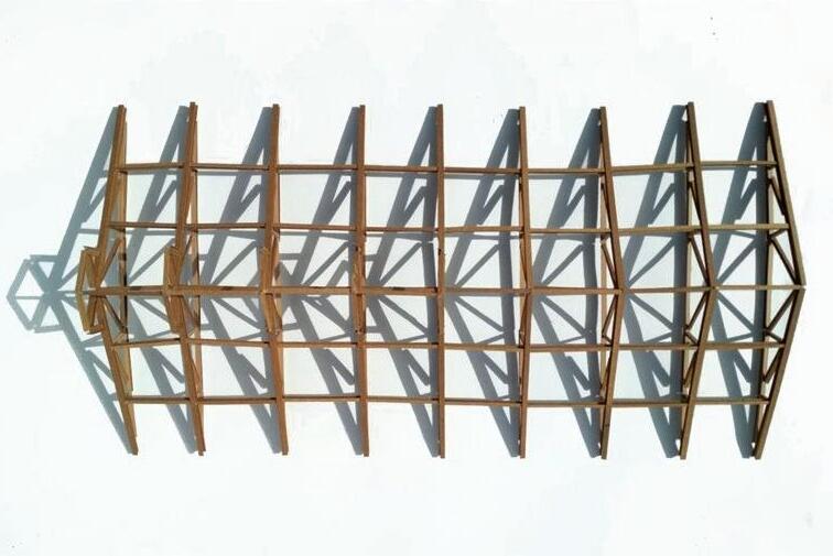
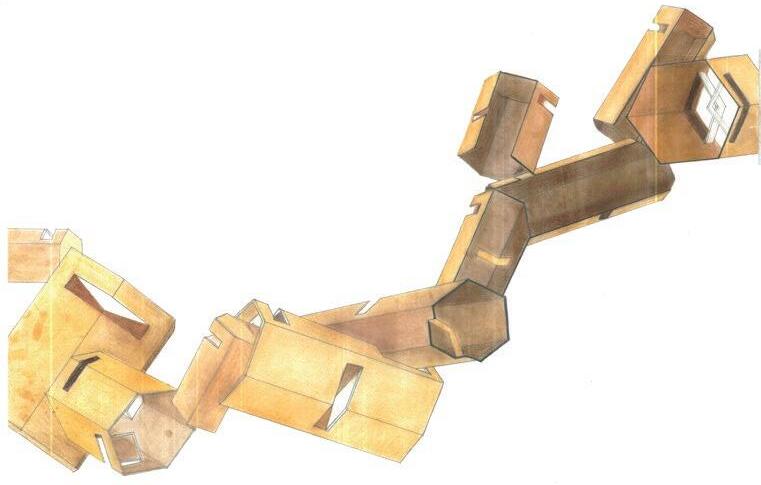
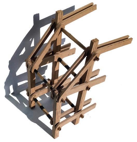
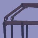
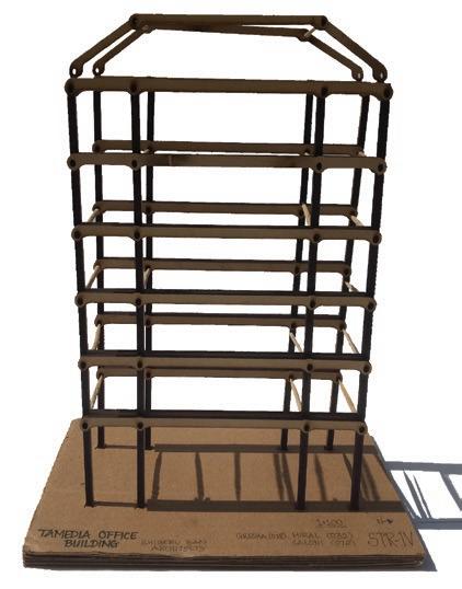
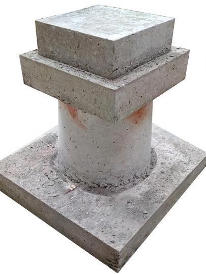
(Above) : Conceptual models for secular, meditative, layering, depth
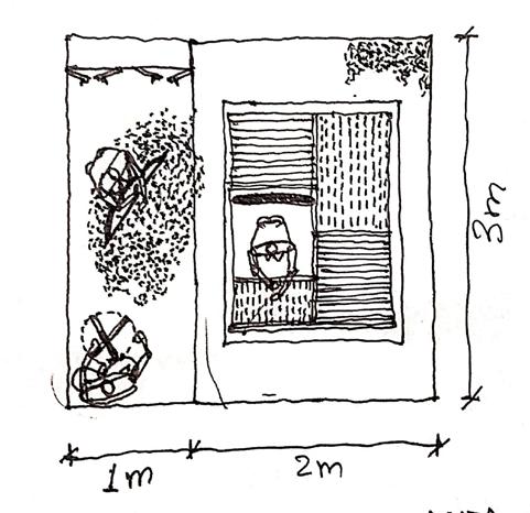
(Above) : Sketches for opening positions and individual space requirement for student Kaksha activity

8
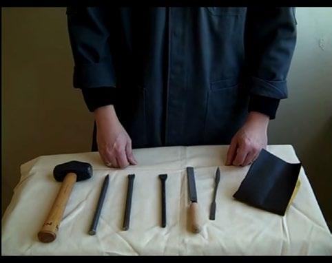
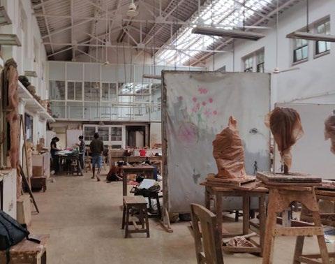
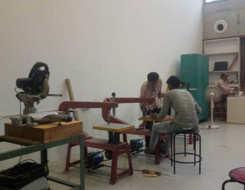
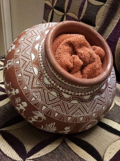
(Above) : Photo documentation of tools, equipments & space usage for student workshop Shala spaces
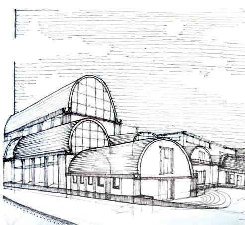
In the design process, we conceptualized on 4 guiding words and how we would like to reflect their meaning in our institutional designs. Thereafter, we prepared abstract models for each of the conceptual stands.
I explored random rubble masonry with RCC vaults to fetch light from small apertures above lintels, and skylight in the centre of the vault for justifying ‘Spanning’ as a concept.
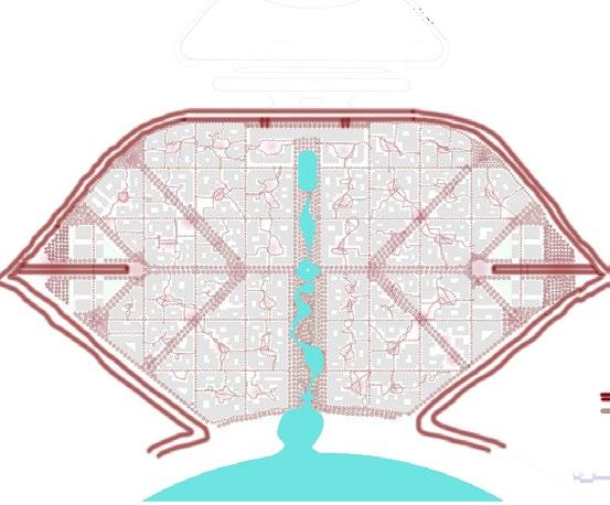
‘Layering’ as a concept was reflected by re-regulating the circulation pattern of students and public visitors within the institute.
‘Gradation’ was developed with deep, long spaces with changing functions and steep site slope.
All sections were developed considering anthropometric dimensions with ‘meditative’ as conceptual guiding principle. All 4 Studios were envisioned as silent cores to find inspirations and 4 Workshops for printing, painting, terracotta and ceramic, and stone sculpting were the heart of the student learning.
We looked up for case-studies and calculated areas for our spaces and referred similiar institutional plans for tweaking our conceptual program and architectural plans (Sangath and Gandhi labour Institute by B.V. Doshi).
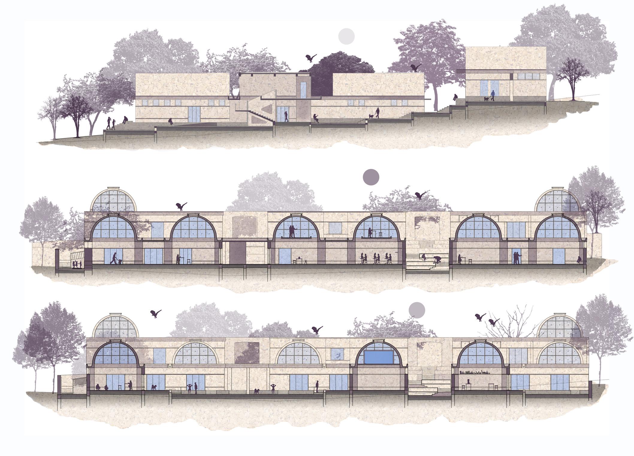
The final set of rendered sections and details (next spread) showcase my understanding of materials, details, and structure from the case-studies.
9
(Above) : Long section cut through the public circulation spine


10 W3 A A 802 + 3850 mm LVL + 7085mm LVL + 3295 mm LVL - 500 mm LVL + 2255 mm LVL + 7645mm LVL + 65 mm LVL SLAB LVL + 4320 mm LVL INSIDE OUTSIDE E 440mm Thk RCC BEAM 110mm high RCC curb wall 130 mm China mosaic strip in elevation 450mm Thk Coursed Random Rubble wall 25mm Bed mortar (for slope) 25 mm China mosaic 75mm Thk Lintel band Sliding window as per detail 75mm Thk RCC Sill band 20mm Thk Terrazzo flooring tile 15 mm Thk base coat 12mm Thk Internal Mala plaster 110 mm high Terrazzo tile skirting 55 mm Thk bed mortar 135 mm RCC SLAB 3720 3565 65mm Thk Paver Blocks 75mm Thk bed mortar with compacted sand filling 135mm Thk RCC slab 150mm Thk BBCC waterproofing 235mm Thk compacted sand filling 460mm Thk Compacted earth filling 65 mm Thk Coping INSIDE 3100 175 120 20 mm 12mm 230 25 mm 12-15mm 5mm 10 mm 235 175 280 + 6100 mm 1335 75 1700 75 380 1320 75 2255 W2 A A 802 1740 40 120 75 435 75 900 3220 565 W 5 A 802 W3 A A 802 + 3850 mm LVL + 7085mm LVL + 3295 mm LVL - 500 mm LVL + 2255 mm LVL + 7645mm LVL + 65 mm LVL SLAB LVL + 4320 mm LVL INSIDE OUTSIDE E 440mm Thk RCC BEAM 110mm high RCC curb wall 130 mm China mosaic strip in elevation 450mm Thk Coursed Random Rubble wall 25mm Bed mortar (for slope) 25 mm China mosaic 75mm Thk Lintel band Sliding window as per detail 75mm Thk RCC Sill band 20mm Thk Terrazzo flooring tile 15 mm Thk base coat 12mm Thk Internal Mala plaster 110 mm high Terrazzo tile skirting 55 mm Thk bed mortar 135 mm RCC SLAB 3720 3565 65mm Thk Paver Blocks 75mm Thk bed mortar with compacted sand filling 135mm Thk RCC slab 150mm Thk BBCC waterproofing 235mm Thk compacted sand filling 460mm Thk Compacted earth filling 65 mm Thk Coping INSIDE 3100 175 235 175 280 + 6100 mm 1335 75 1700 75 380 1320 75 2255 1740 40 120 75 435 75 900 3220 565 W 5 A 802 OUTSIDE 6mm thk, 60x60mm T-angle in elevation 3mm thk, 25 x 25mm L-section screwed Ø 5.0 mm x 20 mm long screw 5mm thk, 50 x 50mm L-section Neoprene lining Glass beading 8mm thk toughened glass 5mm waterproofing and silicon sealant 25mm thk china mosaic and mortar 130mm china mosaic strip in elevation OUTSIDE INSIDE OUTSIDE 6mm thk, 60x60mm T-angle in elevation 3mm thk, 25 x 25mm L-section screwed Ø 5.0 mm x 20 mm long screw 5mm thk, 50 x 50mm L-section Neoprene lining Glass beading 8mm thk toughened glass 5mm waterproofing and silicon sealant 25mm thk china mosaic and mortar 130mm china mosaic strip in elevation OUTSIDE INSIDE
left) : Wall section through admin block (Top right) : Wall section through workshop units (Bottom) : Vault window details- plan and section
(Top
150mm Thk RCC vault at the top
15mm Thk china mosaic
10mm Thk bed mortar
3200mm rise of RCC vault
10mm Thk Internal Mala plaster
100mm strip of china mosaic in elevation
100mm strip of china mosaic in elevation
1:100 slope in bed mortar for
5mm Thk chemical waterproofing


15mm Thk china mosaic
slab (120mm Thk)
400mm wide RCC beam for
10mm Drip mould


100mm Thk RCC Spout
6mm thk chemical waterproofing


OUTSIDE
(Top) : RCC vault and gutter detail (Midde) : Parapet wall, beam and RCC spout (Bottom) : RCC channel and steel grating on plinth beam level
11 E
20 mm Thk stone flooring 50 mm Thk bedding and mortar 120 mm Thk RCC Slab 150 mm Thk BBCC 235 mm Thk sand filling 460 mm Thk compacted earth 450 mm Thk stone wall in coursed random masonry 75 mm THK SILL BAND 75 mm Thk lintel band 150 mm Thk Inverted RCC Beam 500 mm wide gutter 565 mm Beam in elevation mm Thk RCC floor mm Thk mortar 12mm Thk Terrazzo tiles mm THK RCC VAULT mm Thk CHINA MOSAIC 12-15mm Thk Internal mala plaster 5mm Thk, 50 x 50 mm bend L-section for window frame mm Thk toughened glass 12 mm Thk mala plaster Window as per detail drawing 900 540 280 100 800 565 340 110 mm Thk parapet/ curb wall 90mm radii Vata and bed mortar 15 mm Thk china mosaic 3200mm rise of RCC vault 10mm Thk Internal Mala plaster 150mm Thk RCC vault at the top 10mm Thk bed mortar 15mm Thk china mosaic 15mm Thk china mosaic 6mm thk chemical waterproofing 100mm Thk RCC Spout 100mm strip of china mosaic in elevation 100mm strip of china mosaic in elevation 375 Thk random stone masonry 12 mm Thk mala plaster Base coat (15 mm Thk) Skirting (110 mm high) Stone flooring (20 mm Thk) Bed mortar (60 mm Thk) 110 mm Thk parapet/ curb wall 90mm radii Vata and bed mortar 15 mm Thk china mosaic 3200mm rise of RCC vault 10mm Thk Internal Mala plaster 150mm Thk RCC vault at the top 10mm Thk bed mortar 15mm Thk china mosaic 1:100 slope in bed mortar for water drain 10mm Drip mould 5mm Thk chemical waterproofing 400mm wide RCC beam for vault base 250 250 415 80 80 80 80 250 350 Stainless steel plate steel grating 4mm thk, 35x35mm L-section to fix steel grating RCC drain BBCC 1:25mm slope 6mm thk stainless steel grating 6mm thk stainless steel grating 760
Compacted earth (460mm Sand filling (235mm Thk)
180 400 555 735 1135 120 280
BBCC (150mm Thk) RCC
water drain
vault
565 350 Thk STONE WALL Vault internal plaster 12mm thk INSIDE 8mm thk glass 25 x 25mm L-section 5mm thk, 50 x 50mm structural steel L-angle fixing 350mm thk RCC Beam Vault internal plaster 12mm thk mala plaster 80mm vata
base
2. collage URBAN DESIGN
Grid, Walkability, Inferences, Sequential open spaces
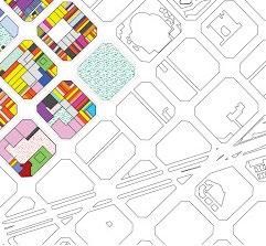
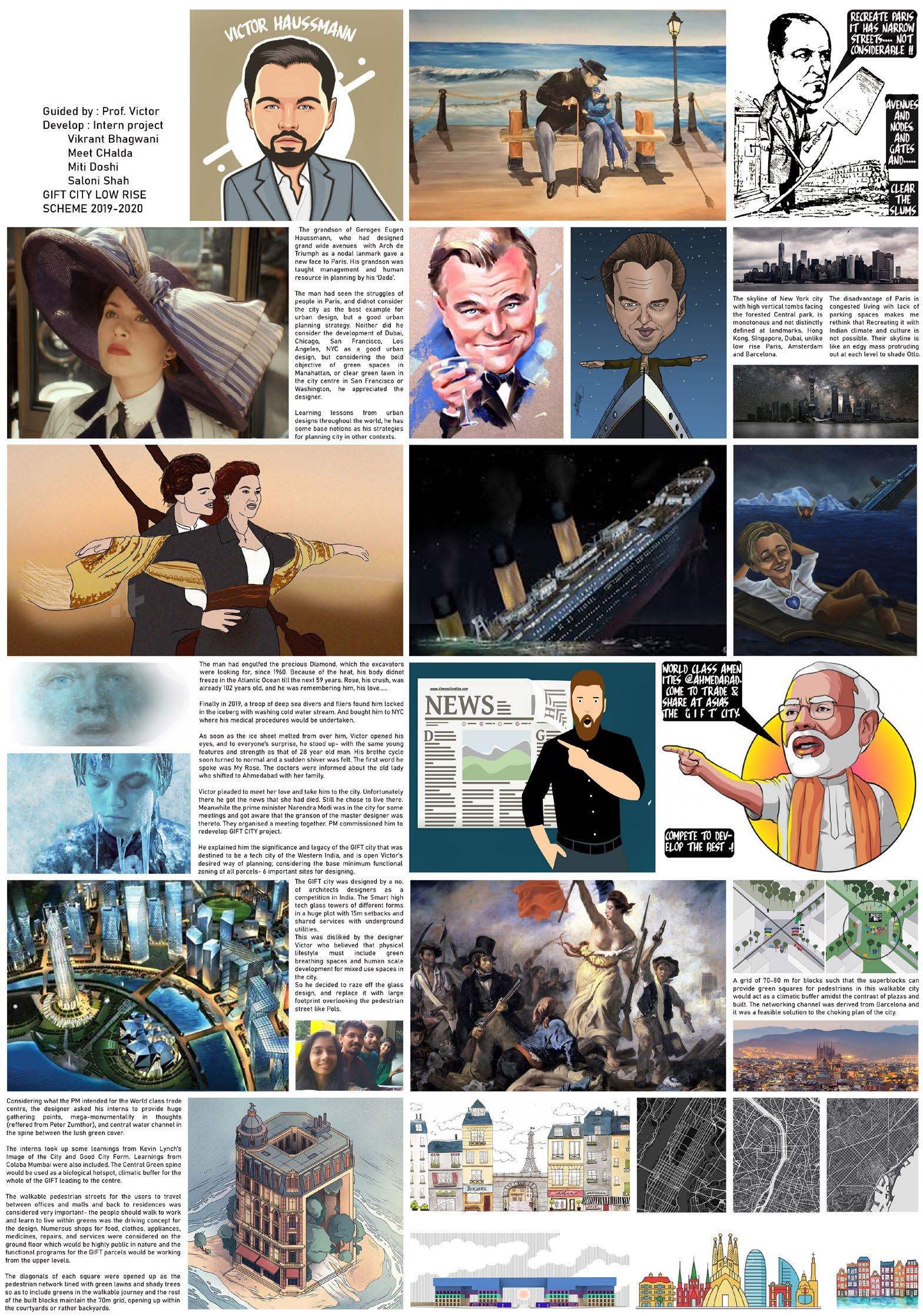
The Urban Design Studio (sem-7) was guided by Ar. Piyas Choudhary and Prachi Patel. Our group designed a collage plan with a narrative story, where a parcel at GIFT City, Gandhinagar of 920mx1175m would have mid-rise mixed-use building blocks with shaded streets for pedestrians and peripheral vehicular avenues for speed transit. 3 Metro stations mark important landmark connections with the given site.
The inference we gathered from the Plan of Paris is providing the shortest routes for connecting plots and an open space/ green area at nodes. Further, the square plot sizes of the Barcelona plan 70-80 meters in length were divided, marking an offset of 6.5m for public walkways with chamfered edges to open up the corners.
Besides this, a remarkable diagonal, characteristic of Barcelona was
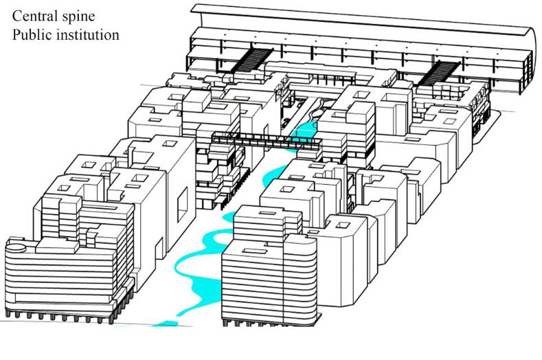
designed and public, cultural public gathering spaces were lined from the axis. Response to Gujarat’s hot and humid climate led us to mark trees at the edge of streets in the linked sequential open spaces. The nooks of plots are opened up to provide small parks. The Central spine like Manhattan, New York is a breathing park with a waterbody to celebrate nature. The mid-rise, high density towers gradually increase with proximity to the Central green Park.
Rapid transit avenue marks the edge of the central spine connecting the diametric extremes. From the Vidhyadharnagar plan, we traced some building plans and aligned them with the plot margins. Indianness was added by carving out courtyards in the buildings. 2 gateways on either side are iconic in scale like MVRDV’s Paris arch. Vehicular transit was restricted with the means of culdesacs and drop off and walkability is promoted within the parcel.
12
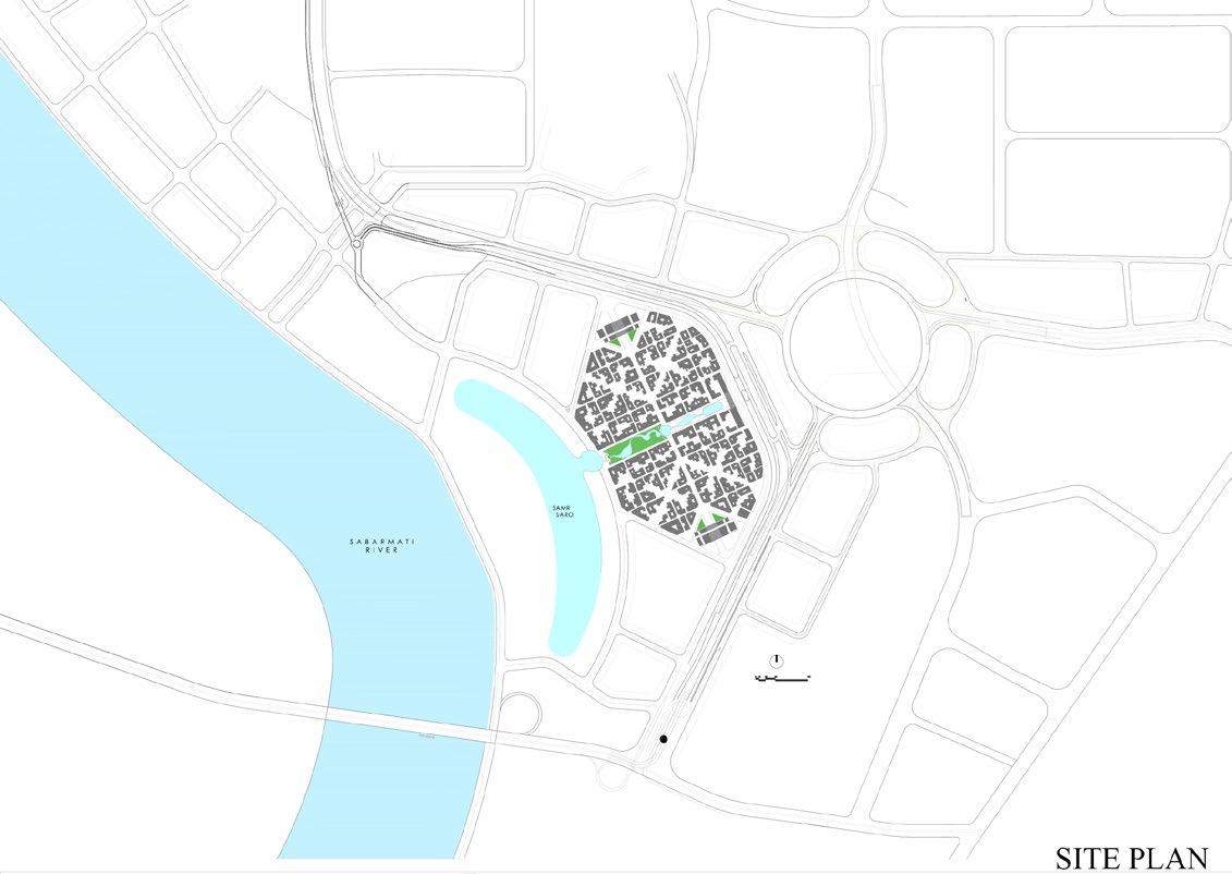
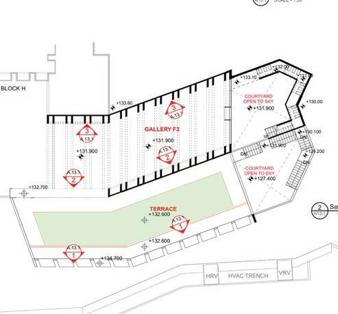
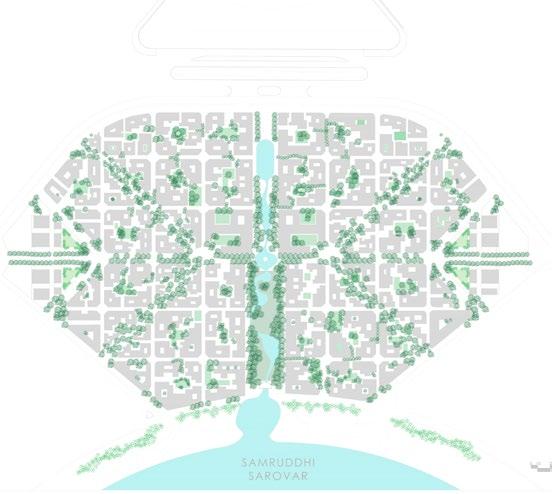
(Top): Site plan of GIFT City, Gandhinagar
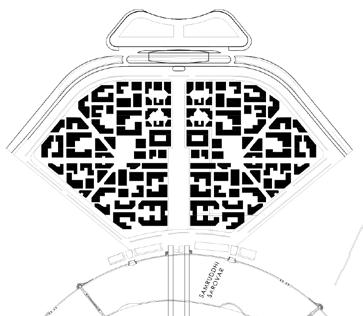
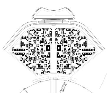
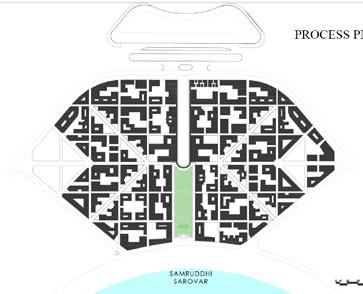
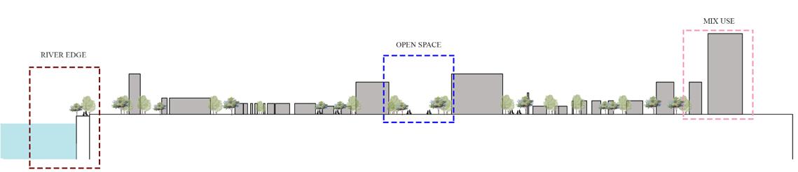
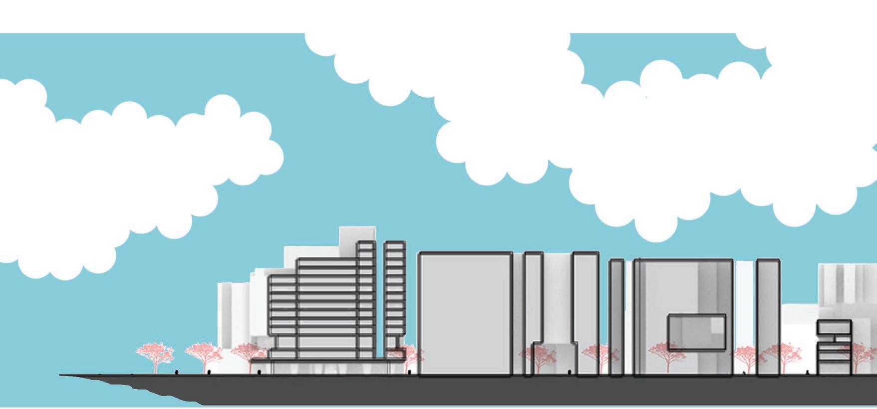
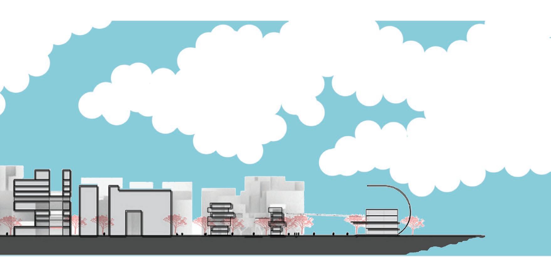
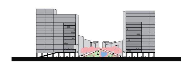
(Above): Process plans for selected plot 900mx1150m and process section (Below): Section through metro station, mixed use public structure
13
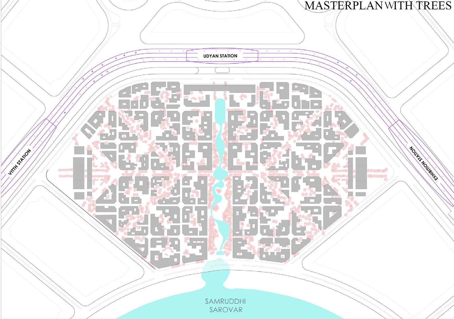
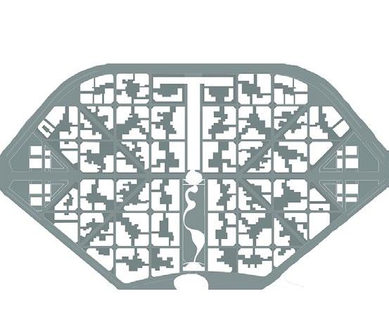
(Above): Parcel plan with buildings, trees and water body
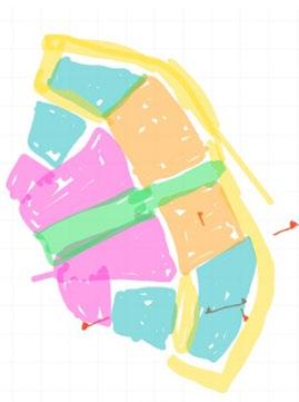
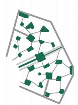
(Above): Process diagrams for developing the 920x1175m plot
Zoning | Transit | Greens | Courtyards & Open spaces | Revised open space | Shortest circulation street (Below): Central spine section through mid-rise, mixed use building
14

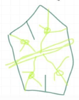
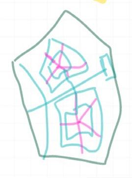
(Above): Underground Parking junctions in the parcel and Parcel grid plan
Functional zoning in the parcel and nodal spill-overs
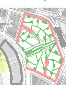
(Above): Vehicular and pedestrian transit, and landscape along the streets
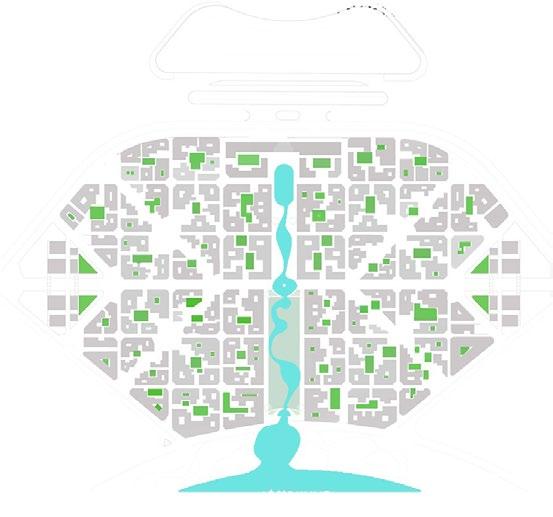
Street connection plan and designed green courts in the plots
15
(Above):
(Above):
16
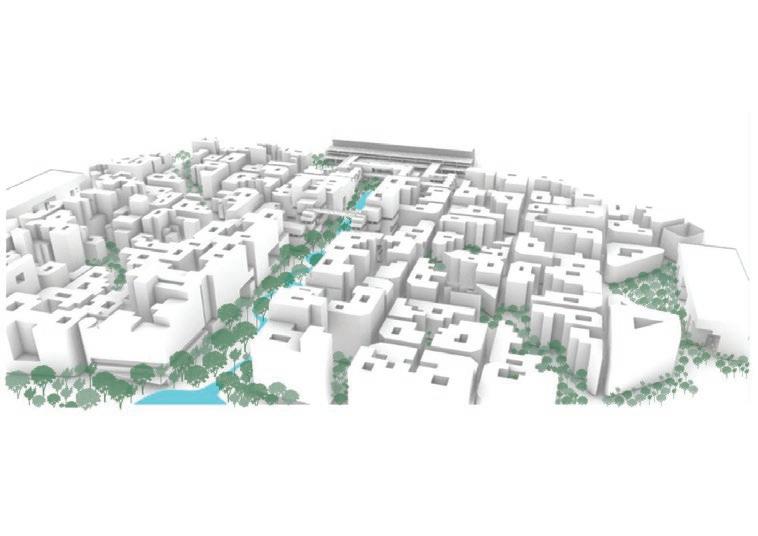
According to our storyline, we were interns at the Paris-based headquarters firm of Prof. Victor. Our design proposal for the GIFT City, Gandhinagar competition draws from international references- the nodal plan of Paris, block grids of Barcelona, and the Central breathing greens like the Manhattan plan.
Our site is surrounded by superfast highways on all sides, 3 metro stations, and a man-made lake on the south. We strategically cut the parcel at the centre providing the central breathing green and connecting the Samruddhi Sarovar to the central concentric plains. Like the
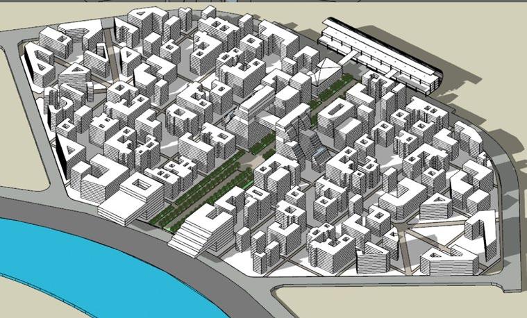
high-rise buildings of New York rising along the trees, we placed our mid-rise public institutions and commercial buildings along the park. Open ground with UG parking and iconic gateway mark the edge of the plots. The metro station was connected with the adjoining commercial complex.
A water feature was developed to attract all age groups for all functions. The highest buildingmixed-use in nature was placed at the heart of the parcel for hospitality and a social landmark. Our process isometrics present our design development throughout the 20 weeks.
17
(Left page): Our comic storyline for the GIFT city design competition led by Shri Narendra Modi (Above): Process 3d view of the central spine connected to the metro station via sleek bridge ramp
3. details of construction
Modular, repitition, symmetry, end junction
E - block in the Smriti-Van Earthquake Memorial is an exhibition gallery housing crafts of Kutchch. The 29-metre long block is a serpentine combination of 3 modules in plan with 5.5 m height.
The exterior retaining walls and RCC portals are dry cladded with 1200 x 900 mm Khavda stone. I
referred the previously issued drawings and started with the principles of symmetry and visual balance. Attempting the details was more engaging because then we questioned the elevations we prepared- it went back and forth. Horizontal groves were sealed with silicon gel and vertical stones were flushed with each other.
18
Drawing and design are the property of Vastu Shilpa Consultants and are not to be copied or used without their permission 670 230 450 230 1,340 230 450 1,800 150 +116.900 GALLERY : FLORA AND FAUNA +117.500 Khavda Stone Dry Cladding (As per Spec.) S S Clamps (As per Spec.) End Khavda Stone Fixed With Klad-X Adhesive Silicon Sealant (As per Spec.) M S Square Box Section 50X50X3 2 MM Vertical line align with beam M S Jali Box Section Khavda Stone Wet Cladding (As per Spec.) M S Square Box Section 50X50X3 2 MM 12mm thk Toughened Glass All Aluminium Frame (Anodizing Color M7 Matt Finish). OUTSIDE 15 A16 9 EQ EQ 115 895 115 115 895 115 115 895 115 415.2 1,125 1,125 1,125 +117.50 +117.50 +123.20 All Aluminium Frame (Anodizing Color M7 Matt Finish). M S Square Box Section 50X50X3 2 MM Vertical line align with beam S S Clamps (As per Spec.) Khavda Stone Dry Cladding (As per Spec.) Centre Of Portal Hair Joint Khavda Stone Dry Cladding (As per Spec.) Centre Of Portal Hair Joint S S Clamps (As per Spec.) Silicon Sealant (As per Spec.) Khavda Stone Dry Cladding (As per Spec.) S S Clamps (As per Spec.) End Khavda Stone Fixed With Klad-X Adhesive Stone jali (as per detailed drawing) INSIDE OUTSIDE OUTSIDE 12mm thk Toughened Glass UP to be cop ed or us GALLERY AND FLORA-FAUNA GALLERY AND FLORA-FAUNA 360 320 965 965 320 965 965 320 965 965 320 965 965 320 965 965 320 965 965 320 965 965 320 965 965 320 965 965 320 965 965 320 965 2 4 9 6 8 0 0 8 0 6 8 0 0 6 8 0 0 6 8 0 0 6 8 0 0 6 8 0 8 0 6 8 0 0 6 8 0 0 6 8 9 4 6 8 9 4 6 2 +114 600 +117 450 +122 000 122 700 123 742 +124 800 Khavda S one Cop ng w th 20 mm p o ec ion (as pe spec ) Khavda S one Cop ng w th 20 mm p o ec ion (as pe spec ) Dry S one C add ng (as per spec F shed F oo Le e F h d F L F h d B B t L Un n shed Ter ace F oo Leve Unf nished Parapet Level Unf n shed Parapet Level
Internship work - 1


19 Drawing and design are the property of Vastu Shilpa Consultants and are not to be copied or used without their permission TYPICAL STONE CLADDING DETAIL 1 A16 11 SCALE - 1:20 65 115 670 115 115 670 115 65 965 965 1,930 200 200 230 450 230 1,340 230 450 1,800 750 150 1,050 End Khavda Stone Fixed With Klad-X Adhesive S S Clamps (As per Spec.) Khavda Stone Dry Cladding (As per Spec.) Khavda Stone Dry Cladding (As per Spec.) S S Clamps (As per Spec.) Silicon Sealant (As per Spec.) Centre Of Portal Hair Joint +116.900 To Align To Align GALLERY : FLORA AND FAUNA EQ EQ 115 895 115 115 895 115 415.2 1,125 1,125 +117.50 +117.50 +123.20 All Aluminium Frame (Anodizing Color M7 Matt Finish). M S Square Box Section 50X50X3 2 MM Vertical line align with beam S S Clamps (As per Spec.) Khavda Stone Dry Cladding (As per Spec.) Centre Of Portal Hair Joint Centre Of Portal Hair Joint Silicon Sealant (As per Spec.) Khavda Stone Dry Cladding (As per Spec.) S S Clamps (As per Spec.) End Khavda Stone Fixed With Klad-X Adhesive Stone jali (as per detailed drawing) INSIDE OUTSIDE OUTSIDE 12mm thk Toughened Glass UP DETAIL PLAN 16 A16 9 SCALE - 1:20 +117.500 GALLERY : FLORA AND FAUNA INSIDE DETAIL PLAN SCALE - 1:20 Slab Cutout DETAIL PLAN 8 A16 6 SCALE - 1:20 200 200 200 230 115 670 115 115 670 115 900 900 +115.700 +115.700 +108.500 A 16 6 A 16 6 Slab Cutout R C C Portal Added From Foundation to 115 700 (Ref Structure DWG - SVB/STR/MUS-E 2 1) Wet Khavda Stone Coping on Top 20mm extension from both side Khavda Stone Dry Cladding (As per Spec.) 12mm thk Toughened Glass All Aluminium Frame (Anodizing Color M7 Matt Finish). End Khavda Stone Fixed With Klad-X Adhesive Silicon sealant (as per specs.) Centre Of Portal Hair Joint Silicon sealant (as per specs.) Khavda stone Dry cladding (as per specs.) OUTSIDE CENTRAL SPINE FLORA FAUNA GALLERY INSIDE +112.10 End Khavda Stone Fixed With Klad-X adhesive S S clamps ( as per specs ) SLOPE To Align To Align SLOPE Square MS-box section 50 x 50 x 3 2 mm Stone Jali ( as per detailed drawing) 200 200 200 +117.500 +117.500 Centre Of Portal Hair Joint End Khavda Stone Fixed With Klad-X Adhesive Khavda Stone Dry Cladding (As per Spec.) 12mm Thk Toughened glass All Aluminium Frame (Anodizing Color M7 Matt Finish). GALLERY : FLORA AND FAUNA INSIDE OUTSIDE +114.60 S S clamps ( as per specs ) wet cladded Khavda coping 20mm projection on all sides Cladding line above 5MM thk Vertical Support M S Plate To Align To Align CLADDING ELEVATION B A 16 1 SCALE - 1 50 GALLERY AND FLORA-FAUNA GALLERY AND FLORA-FAUNA 965 320 965 965 320 965 965 320 965 965 320 965 965 320 965 965 320 965 965 320 965 965 320 965 965 320 965 965 320 360 1 0 0 3 5 0 6 7 8 8 6 7 8 4 6 8 0 0 6 8 0 0 6 8 0 0 6 8 0 6 8 0 0 6 8 0 0 6 8 0 0 6 8 0 0 6 0 0 8 0 6 8 0 9 6 0 +112 100 +116 250 +120 200 120 900 121 942 +122 986 Khavda S one Cop ng w h 20 mm projec on as per spec ) Kh d S C p g h 20 p j p p ) 6mm Groove (as per spec ) Khavda Stone Cop ng w h 20 mm pro ec on as per spec ) Khavda Stone Cop ng w h 20 mm pro ec on as per spec ) D y S one C add ng (as per spec ) F n shed F oor Leve F n shed F oor Leve F n shed Beam Bot om Le e Un n shed Ter ace F oo Leve U f h d P p t L Un n shed Pa ape Leve B A.16.1 B B A.16.1 +112.60 +123.95 +125.00 +126.90 +117.50 +121.10 +121.10 +122.15 +123.20 +123.20 +123.20 +126.90 127.05 +127.20 +127.40 +127.40 +113.94 +113.27 +114.60 +122.90 +119.30 CLADDING KEYPLAN SCALE - 1:100 A A.16.1
3. DETAILS OF CONSTRUCTION INTERNSHIP WORK - 2
Operational detail, Functional, Cost-cutting sheet screwed with the structural frame. The door was designed to be insulating in nature, but porous enough with cuts to remove toxic fumes and particles from the shaft.
This shaft door typical detail was my last drawing during Internship. The following door is part of passageway in the faculty housing in the Masterplan of Nalanda University.
This door is utilitarian in naturefabricated frame out of box section with shera board and gypsum
This door detail was one of a kind drawing in my Internship as this was a small detail in my diverse scale portfolio.
20
Drawing and design are the property of Vastu Shilpa Consultants and are not to be copied or used without their permission 25 EQ 25 EQ 25 EQ 25 8 25 995 25 3 2,250 110 815 125 900 3,300 2,250 110 815 125 100 58 100 58 100 58 100 58 100 58 100 58 100 1,110 3 50 490 25 490 50 3 3 3 50 625 50 3 6 740 100 58 100 58 100 58 100 58 100 58 100 58 100 2 A21 2 A21 1 A21 1 A21 25 x 8 mm Thk 50 x 50 section door stopper Paint / match Self tapping screw Plaster (as per specs.) 40 x 40 x 3mm MS LChannel 50 x 50 x 4 mm MS- Box pipe to fix the door 25 x 25 x 3mm box pipe as support 25 x 25 x 3mm box pipe as support 25 x 25 x 3mm box pipe as support 50 x 50 x 4 mm MSBox pipe as Stopper M S hinge as per specs 8mm thk Shera board with paint to match the walls Concealed handle (as per specs.) Anchor fastener 40 x 40 x 3mm MSL- section 50 x 25 x 3 MS-Box pipe as support Plaster ( as per specs ) 40 x Self L-section in elevation Self tapping screw 40 x 40 L section 25 x 25 Box pipe 8 mm thk board 40 x 40 section 25 x 25 Box pipe Concealed (as per L-section in elevation Groove in plaster Anchor fastener 8mm THk shera board Putty / paint to match with wall 8mm thk shera board M S Hinge ( as per specs.) Self tapping screw Groove in plaster 25 x 25 x 3mm box pipe in elevation Plaster (as per specs) M S Hinge ( as per specs.) HVAC SHAFT 110x74 LV SHAFT 85 5x74 LV SHAFT DOOR (OPENABLE) HVAC SHAFT DOOR (FIXED) 13 Plan +1500mm from FFL 5 A21 SCALE - 1:10 2 A21 B A 21 A A 21 Concealed handle (as per specs.) Self tapping screw 50 x 25 x 3 mm MS Box section Anchor fastener NOTES 1 ALL DIMENSIONS WITH THE STRUCTURAL SHALL BE IMMEDIATELY ARCHITECT BEFORE 2 ALL DIMENSIONS OTHERWISE SPECIFIED 3 ALL LEVELS 4 ALL MARGINS LAWS SHOULD CONTRACTOR IMMIDIATELY BROUGHT BEFORE COMMENCEMENT Date No ALL SHAFT INTERIOR M S hinge as per specs 8mm thk Shera board with paint to match the walls Anchor fastener 40 x 40 x 3mm MSL- section 50 x 25 x 3 MS-Box pipe as support 8 mm thk shera board 8mm thk Shera board with paint to match the walls 40 x 40 x 3mm MSL- section 50 x 25 x 3 MS-Box pipe as support 8 mm thk shera board Plan cut from +1500mm LVL 3 A21 SCALE - 1:5 Anchor fastener 6x6 Groove in plaster 50 Putty/paint to match plaster finish 8mm thk Shera board 25 x 25 x 3mm MS box pipe support 40 x 40 x 3mm MS Lsection in elevation to bind the frame Anchor fastener 50 x 50 x 3mm Box pipe stopper Plan cut through concealed handle 4 A21 SCALE - 1:5 Concealed handle CH100S
(Above): Keyplan for the shaft in the faculty quarters (Below): Elevation and section of service door (Left top): Detail plan view of the door (Left bottom): Plan of the shaft
21 design are the property of Vastu Shilpa Consultants and are not to be copied or used without their permission 25 EQ 25 EQ 25 EQ 25 8 25 995 25 3 2,250 110 815 125 900 3,300 2,250 110 815 125 100 58 100 58 100 58 100 58 100 58 100 58 100 100 58 100 58 100 58 100 58 100 58 100 58 100 2 A21 2 A21 1 A21 1 A21 25 x 25 x 3 MS- Box section 8 mm Thk Shera Board 50 x 50 x 4 MS- box section in elevation as door stopper Paint / putty to match with wall Plaster ( as per specs ) 40 x 40 x 3 MS L-section Self tapping screw L-section in elevation Self tapping screw 40 x 40 x 4 mm MSL section 25 x 25 x 3 mm MSBox pipe 8 mm thk shera board 40 x 40 x 4 mm MS-L section 25 x 25 x 3 mm MSBox pipe Concealed handle (as per specs) L-section in elevation Groove in plaster 8mm thk shera board M S Hinge ( as per specs.) Self tapping screw Groove in plaster 25 x 25 x 3mm box pipe in elevation Plaster (as per specs) M S Hinge ( as per specs.) LV SHAFT DOOR (OPENABLE) HVAC SHAFT DOOR (FIXED) Section of Shaft door 2 A21 SCALE - 1 10 B A 21 A A 21 Concealed handle (as per specs.) Self tapping screw
3. details of construction
This project is one of the prestige projects commissioned by the state government with a motto to ‘plant a tree for each victim’ of the 2001 Bhuj Earthquake. The master plan of the Bhujiyo Dungar included the restoration of the fort wall, the design of a new museum and sun-point memorial, and the positioning of a no.of step-wells of different sizes on the hill to commemorate the dead.
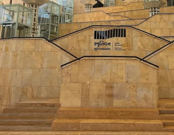
H - block in the Smriti Van Museum is an Earthquake Stimulator block, where one can once again experience the ghastly calamity of 2001. The block contains several graphs, pictures, and visuals designed and placed to convey information to the visitors about the facts, figures, values, and atmosphere post-earthquake.
The 23-meter-long block is a square in plan with 5.5 m height with RCC portals. It contains a lobby, a stimulating platform, and a circumambulating passage lined with services on the east.
This block is the end of the central spine, which is shaded by a tensile fabric structure. This museum contains seven museum blocks demonstrating the life, crafts, people, values, and clothing of Kutchch.
I learned a system of dimensioning, marking, call-outs remarks, and line types in this working drawing set. While developing the plans and sections, the architects collaborated with the consultant to make several structural changes and revisions with respect to site, contours, levels and adjoining structure.
22
the property of Vastu Shilpa Consultants and are not to be copied or used without their permission Title Checked Dealt Scale Date NOTES ARCHITECTURAL VASTU Architects Sangath Phone www No Date Key Revisions Distribution Consultants SMRITI Project 1 CO DRAWINGS IMMEDIATELY ARCHITECT WORK 2 UNLESS 2 BLOCK Y1 Y2 Y5 Y6 Y7 Y8 Y9 Y10 Y11 Y12 Y13 Y14 Y15 Y16 Y17 Y18 Y19 Y20 Y21 SECTION H1 A 4 1 SCALE - 1 100 +128.650 +130.300 +131.000 +131.900 +140.950 +142.100 +144.200 175 70 80 160 15 55 15 80 450 200 255 115 104.2 105.8 905 115 210 Parapet Fin Lvl Slab Unfin Lvl Beam bottom Lvl Floor Fin Lvl LOBBY Passage Fin Lvl Floor Fin Lvl Y3 Y4 Floor finish (as per specs) Fixed Glass (as per detailed drawing) Plinth details ( as per detailed drawing) Plinth details ( as per detailed drawing) SECTION H2 A 4 1 SCALE - 1:100 X2 X3 X4 X5 X6 X7 X8 X9 X10 X11 X12 X13 X14 X15 X16 X17 X18 X19 X20 X21 X22 X23 SX22 SX23 X24 X1 X26 +128.650 +130.300 +131.000 +131.900 +132.400 +135.735 +135.800 +139.700 +140.950 +142.100 +144.200 80 905 115 210 63.5 16.5 905 115 104.2 105.8 225 Parapet Fin Lvl Slab Unfin Lvl Beam bottom Lvl Slab Fin Lvl Tank Fin Lvl Floor Unfin Lvl LOBBY FIRE WATER TANK CORRIDOR Landing Fin Lvl Floor Unfin Lvl Floor Unfin Lvl LOBBY Parapet Fin Lvl 150 15 55 15 60 50mm Expansion joint Plinth details ( as per detailed drawing) Railing (as per spec) NO 1 2 1 3 Drawing and design are the property of Vastu Shilpa Consultants and are not to be copied
Internship work - 3 Articulaion, correspondence work, Simulations
(Above): Plan of H-block (Below left): Section cut through centre of the block (Bottom middle): Long Section cut through staircase (Bottom right): Call-out Section through service shaft
23 the property of Vastu Shilpa Consultants and not to be copied used without their permission D1 Y3 Y3 Y5 Y5 Y7 Y7 Y9 Y9 Y11 Y11 Y13 Y13 Y15 Y15 Y17 Y17 Y19 Y19 Y21 Y21 Y20 Y20 Y18 Y18 Y16 Y16 Y14 Y14 Y12 Y12 Y10 Y10 Y8 Y8 Y6 Y6 Y4 Y4 Y2 Y2 X4 X4 X6 X6 X8 X8 X10 X10 X12 X12 X14 X14 X16 X16 X18 X18 X20 X20 X22 X22 X21 X21 X19 X19 X17 X17 X15 X15 X13 X13 X11 X11 X9 X9 X7 X7 X5 X5 X3 X3 X2 X2 X23 X23 Y22 Y22 Y1 Y1 AY21 AY17 AY8 AY3 SX23 SX22 X24 X24 X1 X1 D2 LX24 L23 LX25 X25 X26 X26 Y23 Y23 450 23 59 23 127 30 45 30 120 30 45 30 120 105 795 105 120 30 45 30 120 30 45 30 127 23 59 23 23 59 23 127 30 45 30 120 30 45 30 120 30 45 30 120 30 45 30 120 30 45 30 120 30 45 30 120 30 45 30 120 30 45 30 120 30 45 30 127 23 59 23 17.5 82 180 45 180 45 180 45 180 45 180 45 180 45 180 45 180 45 180 45 180 82 473 82 153.5 75 150 75 150 75 150 75 150 75 150 75 150 75 150 75 150 75 153.5 82 20.2 427.5 25 2,369 23 59 23 127 30 45 30 120 30 45 30 120 30 45 30 120 30 45 30 120 30 45 30 120 30 45 30 120 30 45 30 120 30 45 30 120 30 45 30 127 23 59 23 82 180 45 180 45 255 795 255 45 180 45 180 82 2,369 23 59 23 127 30 45 30 120 30 45 30 120 30 45 30 120 30 45 30 120 30 45 30 120 30 45 30 120 30 45 30 120 30 45 30 120 30 45 30 127 23 59 23 11.5 82 153.5 75 150 75 150 75 150 75 150 75 150 75 150 75 150 75 150 75 150 85.5 473 2,369 2,369 15 678.2 22.5 560 22.5 1,000 22.5 370 22.5 582.5 1,022.5 392.5 11.2 678.2 2,020 450 99.8 182.5 245 5 686.5 200 59 40.5 432.5 411.2 200 487.3 200 211.2 152.6 120 200 222.5 422.5 400 300 +131.900 +131.900 +131.900 +133.250 +134.600 +135.650 +138.80 +140.45 +137.15 +141.65 +131.000 +131.700 +131.700 +131.900 +132.400 +132.400 R 400.1 R 852.5 H6 A 4 1 H6 A 4 1 H5 A 4 1 H5 A 4 1 Retaining Wall BLOCK G BLOCK F 1000mm Dia Spine columns 1000mm Dia Spine columns BLOCK F As per str drawing As per str drawing 1 2 3 4 5 6 7 8 9 10 11 12 13 14 T 300mm R 150mm UP UP H2 A 4 1 H2 A 4 1 H4 A 4 1 H4 A 4 1 450 82 180 45 180 45 180 45 180 45 180 45 180 45 180 45 180 45 180 45 157 23 82 153.5 75 150 75 150 75 150 75 150 75 150 75 150 75 150 75 150 75 150 85.5 473 11.5 82 153.5 75 150 75 150 75 150 75 150 75 150 75 150 75 150 75 150 75 153.5 82 472.7 82 180 45 180 45 180 45 180 45 180 45 180 45 180 45 180 45 180 45 180 82 352 2025.1 3 20 477.4 499.5 1,079.5 893 +130.400 59.05° 59.05° H1 A 4 1 H1 A 4 1 H3 A 4 1 H3 A 4 1 50mm Expansion joint Sump as per str.) Sump (as per str.) Railing (as per specs.) LIFT Tile Drop LOBBY DN DN DN DN LIFT LIFT PUMP ROOM Fire Water tank Domestic Water tank HPS ROOM copied or used without their permission NOTES Date Remarks No Date Prints Issued to Date Prints Issued to Key Plan Revisions Distribution of Prints GOOD FOR CONSTRUCTION 1 ALL DIMENSIONS SHALL BE CHECKED AND CO-RELATED WITH THE STRUCTURAL DRAWINGS AND ANY AMBIGUITY SHALL BE IMMEDIATELY BROUGHT TO THE NOTICE OF THE ARCHITECT BEFORE COMMENCEMENT OF THE WORK 2 ALL DIMENSIONS ARE IN CENTIMETERS UNLESS AND OTHERWISE SPECIFIED 2 ALL LEVELS ARE IN METERS Y2 Y3 Y5 Y6 Y7 Y8 Y9 Y10 Y11 Y12 Y13 Y14 Y15 Y16 Y17 Y18 Y19 Y20 AY21 SECTION H3 A 3 2 SCALE - 1:100 Y4 Y1 +131.900 +133.250 +134.600 +135.650 +137.150 +138.800 +140.450 +141.600 +142.100 +143.142 +144.200 +147.250 955 60 165 305 60 15 Parapet Fin Lvl Slab Unfin Lvl Parapet Unfin Lvl Landing Fin Lvl Landing Fin Lvl Landing Fin Lvl Landing Fin Lvl Landing Fin Lvl Landing Fin Lvl Floor Fin Lvl LIFT STAIRCASE Opening lvl in lift Plinth details ( as per detailed drawing) DIMENSIONS TAGS NO 7950 x 4500 D1 1 D2 2 LINTEL 4500 2250 1500 x 2250 DOOR SCHEDULE WINDOW SCHEDULE 600 X 600 W1 1 15450 1270 x 2250 3 D3 2250 Drawing and design are the property of Vastu Shilpa Consultants and are not to be copied or used without their permission SECTION H5 A 3 2 SCALE - 1 100 +131.900 +135.685 +135.800 +142.100 +146.750 3,670 95 9,550 650 2,250 2,400 Floor Fin Lvl Top of Parapet Lvl Top of slab Lvl Floor Fin Lvl Top of Parapet Lvl
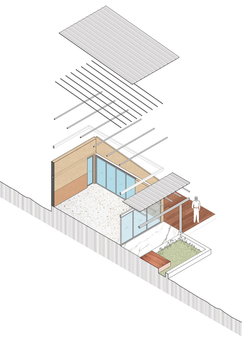
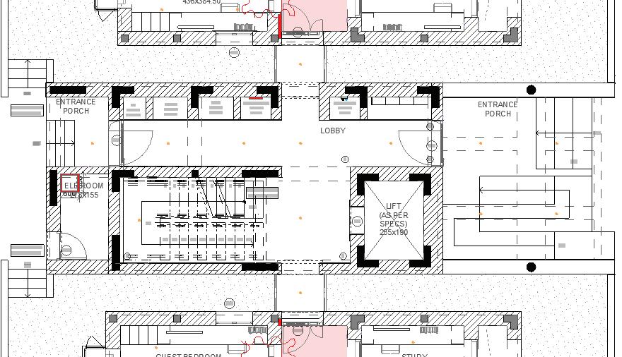
4. house extension at sanand Professional office work
Retain, refurbish, redress, rate
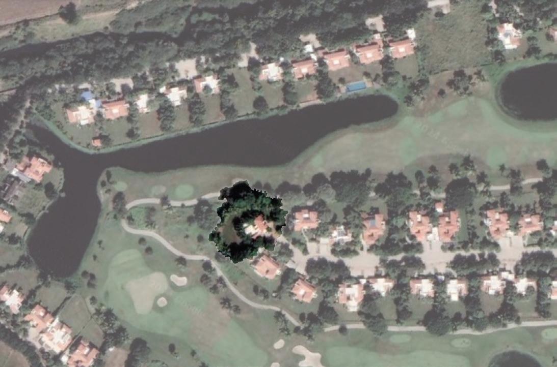
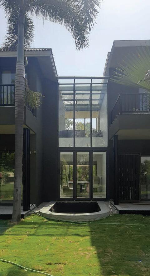
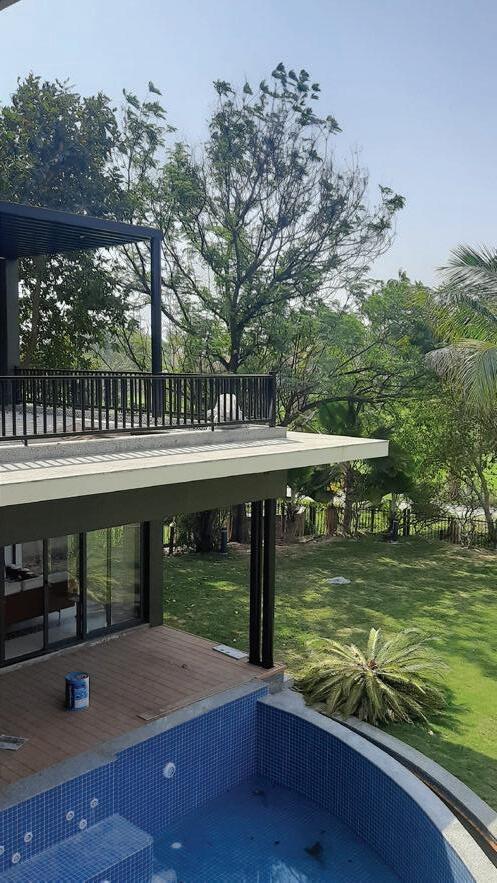
This is an ongoing renovation and extension project at Kalhaar Blues and Greens, Sanand. We added a jacuzzi pool, deck, 2 bedrooms, gallery wall, pergola pavilion, and a double-height space for dinning in the existing house. Openings were enlarged to fetch the views of the landscape, golf course, and the lake beyond.
The project was running on tight deadlines (4.5 months) as the client intended to re-inaugurate the weekend home at his wedding. The ground floor was envisioned with a cool color palette, and the upper floor with extension spaces were developed with a warmer palette.
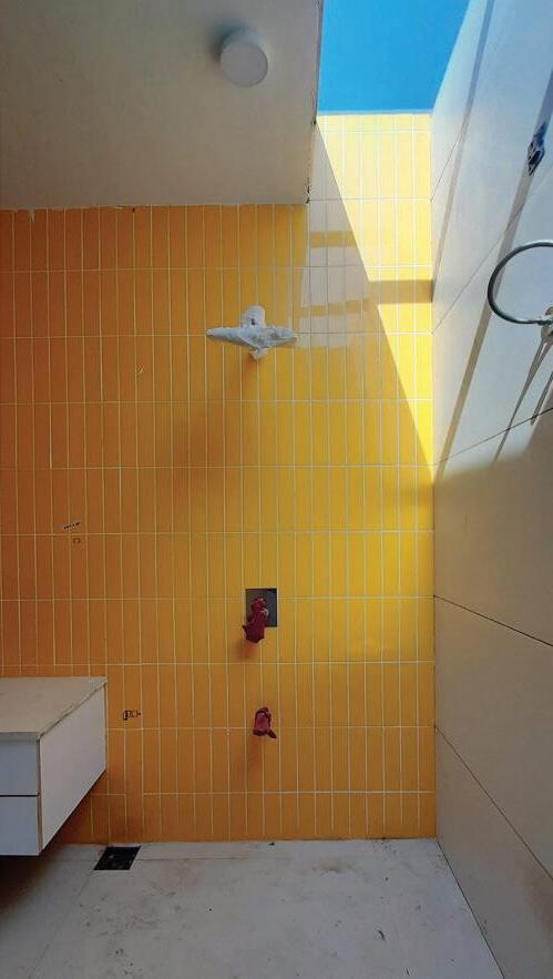
The striking feature of the house was the double-height glass box for the dining room and skylight for
Site area : 12400 m2
GF Carpet area : 350 m2
the upper floor bathroom. The balconies on the upper floor were extended as floating slabs to enjoy the view from the bedrooms, therefore, redundant walls were demolished and hollow, sleek metal-double columns were added on the lower floor to support the 3-meter wide balconies. Patterned tiles set the tone for each of the interior spaces.
KalakaariHaath wallpapers and asian paints wallpapers locked under the dado rail, were applied in the interior spaces accompanied by patterned tiles. The existing railing was replaced with sleek MS sections and wooden windows were converted to full-height sliding shutters. All bathrooms were redressed. The pergola on the terrace was perfectly placed to capture the moody sunset.
House Extension project at KBG, Sanand
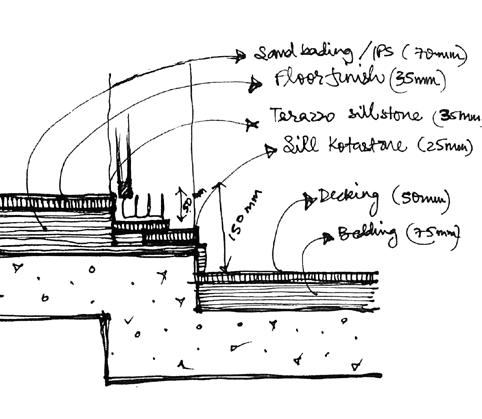
24 SECTION AA' Ground Level Parapet Level BEDROOM - II COVERED DECK KITCHEN AND SERVICE YARD KITCHEN COVERED ENTRYWAY SERVICE DUCT COVERED PERGOLA ON TERRACE 2900 950 2740 3120 2740 1200 600 1050 Ground Floor Finished Level New Extension Lintel Glass window Pergola as per fabricator's details 2400 100 Finished terrace Level Fabricated metal staircase as per architect's details 1 2 4 5 Ground Level 6 300 230 mm thick brick masonry wall 450 Sloping roof as per existing site conditions 230 mm thick brick masonry wall asp per site conditions 950 Existing Lintel Level 100mm thick Lintel added for extension RCC slab as per structural engineer's details 2600 450 450
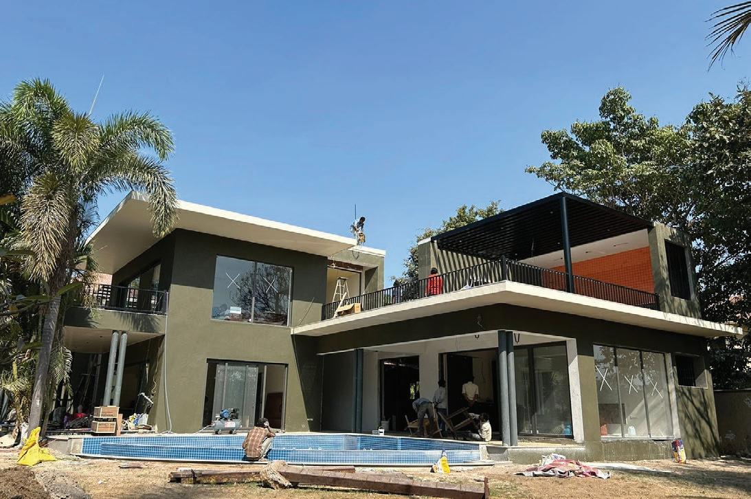
(Above): Photograph of ongoing office project (Left bottom): Long section AA through extension bedroom and services (Right bottom): Short section EE cut through pool & extension bedroom
25 SECTION AA' Ground Level Parapet Level BEDROOM - II COVERED DECK KITCHEN AND SERVICE YARD KITCHEN COVERED ENTRYWAY SERVICE DUCT COVERED PERGOLA ON TERRACE 2900 2740 2740 Ground Floor Finished Level New Extension Lintel Glass window Pergola as per fabricator's details 2400 100 Finished terrace Level 1 Ground 6 300 450 950 Existing Lintel Level 100mm thick Lintel added for extension 2600 450 SECTION EE' Ground Level Parapet Level Finished Terrace Level Ground Level DECK BEDROOM - II PLUNGE POOL Pool Finished Level 900 2900 3120 950 950 1465 700 900 BATHROOM Pergola as per fabricator's details Finished floor Ground Floor Finished Level New Extension Lintel Level 1500 900 RCC slab as per structural engineer's details 300 35 2400 Stone coping 230 mm thick brick masonry wall RCC slab as per structural engineer's details F E D 230 mm thick brick masonry wall 100 mm thick Lintel added for Extension 450 2400 800 950 2100 First Floor Beam Bottom Level RCC slab as per structural engineer's details 1200 Infinity pool edge detiails as per pool consultant 2725 325 325 175 PERGOLA ON TERRACE
(Above): Google map image of site at Kalhaar blues & greens


Electrical layout of ground floor where red marks the new extension over the existing built
26 Meter Room Service Duct Service Duct S15 S24B S25 S17 S34 S33 S35A S31 S3 S24A S26 S18 S23 S4 S6 S7 S9 S2 S29 S28 S30 S27 S5 1000 1000 1000 600 600 1500 1500 1130 300 2870 3115 1875 1150 1150 1150 1380 2300 1210 450 980 980 1500 1500 4030 1380 2390 945 945 970 1555 S8 1800 600 600 1800 900 900 2400 2400 1200 975 1500 1500 975 1200 1200 4950 1200 S1 2190 450 450 2190 900 1745 1740 900 1050 S16 2435 1800 2355 300 1345 1500 1740 750 2775 300 1200 300 2775 300 1200 300 2775 300 2775 1200 900 1350 1350 600 300 675 300 1800 300 675 S32 825 825 1275 2250 300 600 1350 1350 900 1050 1050 900 1800 900 900 1800 1130 435 435 1800 1800 1800 900 1800 900 1050 300 1950 1950 1950 1950 1300 1300 1655 1655 1655 900 900 900 900 2300 1225 505 300 600 2400 2400 1200 1200 1200 1800 1800 450 2150 1200 1200 1200 1200 2130 3670 2265 S21 450 300 S22 450 S20 900 S19A 300 S10 S11 S12 S13 S14 900 2640 C C C Db Electrical layout as per Electrical layout as per Bathroom drawings Bathroom drawings toilet drawings existing site conditions Hanging light above S19B 1100 S35B 1495 1495 A A' E E' 1 2 3 4 5 6 7 8 9 10 C

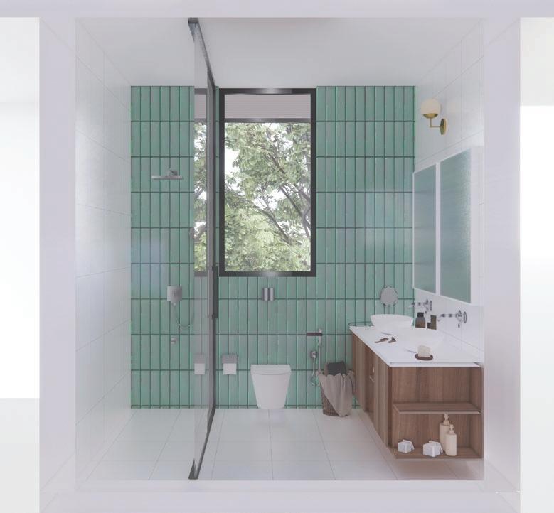
(Left): Render for the groundfloor bathroom (Below): Redressed GF Bathroom details
Please

27 Zoom detail A 360 900 50 10 10 10 25 25 Dividein4equalparts Reference
note that this is only a 50mm wide, 3-5mm thick MS steel plate handrail to be welded with vertical supports 20m or 25mm thick steel rod as per fabricator's details 10mm or 15mm thick steel rod as per fabricator's details 10mm thick steel rod as per fabricator's details to be welded with horizontal supports 15 15 15 10mm thick steel rod as per fabricator's details to be welded with horizontal supports Staircase as per existing site conditions Wooden handrail 300 300 300 300 300 300 300 300 300 300 300 300 300 300 300 300 300 5400 900 300 300 900 900 450 3200 250 Divide total height in equal parts 175 175 175 175 175 175 175 175 175 175 175 175 175 175 175 175 175 175 175 175 175 175 175 175 175 175 175 175 175 175 175 175 175 175 175 175 175 175 75 900 300 175 1 2 3 4 5 6 7 8 9 10 11 12 13 14 15 16 17 250mm wide, 18-20mm thick black powder coated MS steel plate stringer beam A' 00mm Ground Level Kitchen and service Yard +450mm Ground Floor Finished Level +3650mm Finished terrace Level 18 Elevation A UP 2 3 4 5 6 7 8 9 10 11 12 13 14 15 16 17 18 3 3-5mm thick black powder coated perforated MS steel plate tread Extension bedroom External Staircase Elevation A External Staircase Section AA' Staircase 50mm away from wall edge Refer detail A Elevation B 250mm wide, 18-20mm thick black powder coated MS steel plate stringer beam 3-5mm thick black powder coated perforated MS steel plate to be welded with 40x40mm L-section 250mm wide, 18-20mm thick black powder coated MS steel plate stringer beam 19 20 21 19 20 21 Railing welded to the stringer beam 40x40mm, 5mm thick black black powder coated L-section welded with stringer beam 300x900mm, 3-5mm thick black powder coated perforated MS steel plate tread 250mm wide, 18-20mm thick black powder coated MS steel plate stringer beam 75mm high, 3-5mm thick black powder coated perforated MS steel plate 175 2 4 5 6 7 8 9 10 11 12 13 15 14 16 17 19 18 20 21 +3650mm Finished terrace Level 3650 0mm Ground Level +3650mm Finished terrace Level 0mm Ground Level A 8-10mm thick, 50mm wide steel plate handrail Existing staircase with modified railing New staircase refurbished from old
Ground floor Existing Bathroom Fixture layout Ground floor Existing Bathroom Tiling layout Shower Arm, spout, and diverter/mixer WC with concealed flush tank and flush valve as per selection on existing site location Selected matt white tile 1200 x 600 mm to be applied with fit joints (no grouting) Slope 975 975 410 410 410 410 Opening and window exhaust as per selection 2-way bib cock with health faucet as per selection on existing location Countertop wash basin with wall mounted mixer as per selection Slope Geyser point provision Door and threshold as per existing site condition NT NT A Folded Elevations - Ground floor Existing Bathroom C B A D B C 450 D 600 25mm drop 25mm drop 2125 1050 750 2100 2125 750 300 Control valve as per existing site conditions 585 600 600 600 600 600 75 915 870 815 750 750 1200 1200 1025 450 650 C B A D Ground floor Existing Electrical layout 975 975 450 450 410 410 885 975 975 SB1 SB2 2 - -3 1 -Sr no. Light point Fan and Exhaust Plug point (6A points) Plug point (16A points) Geyser point 1Selected matt white tile 1200 x 600 mm to be applied with 3mm horizontal grouts Selected matt white tile 1200 x 600 mm to be applied with 3mm horizontal grouts Selected 107M blue tile 260 x 65mm to be applied with 3mm grouts on all sides 260 260 260 260 260 260 260 260 260 260 260 215 SB1 300 Control valve Opening and window exhaust as per existing site condition Concealed flush tank with flush valve as per selection Glass partition WC as per selection on existing site location 2-way bib cock with health faucet as per selection on existing site location SB2 Wall mounted mixer as per selection Countertop wash basin as per selection Spout Diverter/ mixer Shower arm 350 Stone countertop to be cladded with selected matt white floor tile Geyser point provision Door as per existing site condition 25mm drop Stone countertop cladded with selected matt white tile NT location and slope as per existing site conditions 600 600 600 150 1200 815 2600 450 600 600
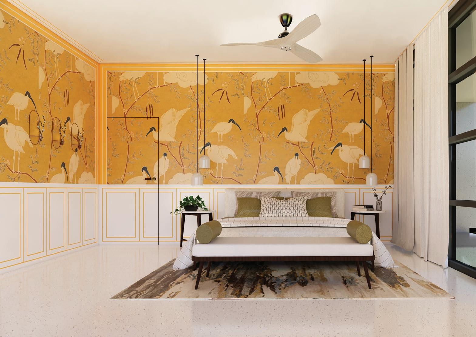
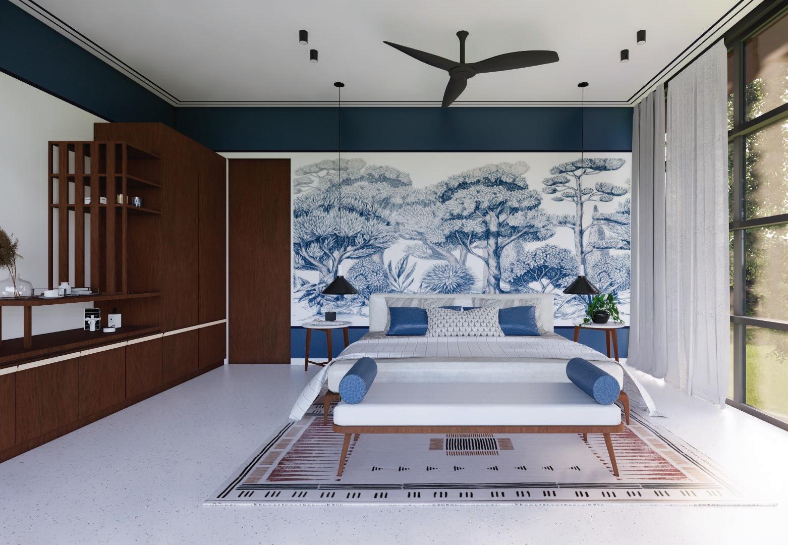 (Above): Cool colour themed GF Extension bedroom proposal
(Above): Warm colour themed FF Extension bedroom proposal
(Above): Cool colour themed GF Extension bedroom proposal
(Above): Warm colour themed FF Extension bedroom proposal


600 450 100 450 100 1900 225 375 225 355 600 600 50 450 50 100 1900 600 20 Elevation A Drawer Drawer Drawer A SWB Elevation A SWB Section AA Drawer Drawer Drawer A Inner laminate as per selection Veneer/ laminate as per selection Elevation A A Veneer / Laminate as per selection 50mm dia curve in stacked plywood Plan - Upper level plan Plan - Lower level plan B B Align the table top with wooden window jamb Packing Inner laminate as per selection Handle and hardware as per selection Veneer/ laminate as per selection 50mm fillet edge curve in plan B B Align the table top with wooden window jamb 50mm fillet edge curve in plan Veneer/ laminate as per selection Back treatment using 2mm thick insulating sheet 600 450 100 450 100 1900 225 375 225 355 600 600 50 450 50 100 50 450 50 100 1900 600 20 Elevation A Drawer Drawer Drawer A SWB Elevation A SWB Section AA Drawer Drawer Drawer A Inner laminate as per selection Veneer/ laminate as per selection Elevation A A A Veneer / Laminate as per selection 50mm dia curve in stacked plywood Plan - Upper level plan Plan - Lower level plan B B Align the table top with wooden window jamb Packing Inner laminate as per selection Handle and hardware as per selection Veneer/ laminate as per selection 50mm fillet edge curve in plan B B Align the table top with wooden window jamb 50mm fillet edge curve in plan Veneer/ laminate as per selection Back treatment using 2mm thick insulating sheet 225 355 355 225 600 600 50 450 50 100 50 450 50 100 1900 20 20 SWB Section AA Drawer Drawer Drawer Section BB A Elevation A A A Veneer / Laminate as per selection 50mm dia curve in stacked plywood Plan - Lower level plan Align with window bottom Inner laminate as per selection Veneer/ Laminate as per selection Handle and hardware as per selection Architect Client Project Scale Date Drawn by Drawing No. Drawing Title Shah Family KBG House Furniture GF old This drawing is or used in part Drawings to W.D. Vaissnavi B.Arch, CEPT M.Des, Harvard shukl.vaissnavi@gmail.com +91-9909758881 All dimensions Packing Inner laminate as per selection 50mm fillet edge curve in plan B B Drawer Align the table top with wooden window jamb 50mm fillet edge curve in plan treatment thick sheet 600 450 100 450 100 1900 225 375 225 355 600 600 50 450 50 100 50 450 50 100 1900 600 20 Elevation A Drawer Drawer Drawer A SWB Elevation A SWB Section AA Drawer Drawer Drawer A Inner laminate as per selection Veneer/ laminate as per selection Elevation A A A Veneer / Laminate as per selection 50mm dia curve in stacked plywood Plan - Upper level plan Plan - Lower level plan B B Align the table with wooden window jamb Packing Inner laminate as per selection Handle and hardware as per selection Veneer/ laminate as per selection 50mm fillet edge curve in plan B B Align the table top with wooden window jamb 50mm fillet edge curve in plan Veneer/ laminate as per selection Back treatment using 2mm thick insulating sheet Architect Vaissnavi Shukl House Extension Drawing Title Artwork elevations Scale NTS All dimensions in millimeters (mm). Drawings to be read only and not to be measured. Green room Elevation for Artwork 2755 1500 S1 25 100 25 100 Wooden frame in the opening as per existing site conditions 20mm or 25mm wide, White paint strip in elevation Green shade as per selection 100 25 100 25 325 100 False ceiling as per existing site condition 20mm or 25mm wide, White paint strip in elevation 2790 100 25 25 100 EQ EQ 75mm high, matt white flooring tile skirting as per selection (Above): Existing GF bedroom wall elevation for appliance, artwork and finished colourwork (Above): Bedroom T.V. unit design
5. extra works
Workshops, model-making, sketching, hand renders, interior design renders, office renders, artwork, installation, social work

30

31
sssaloni9991@gmail.com
32
you
time
attention
S.Shah
Thank
for your
and
Saloni
sssaloni991@gmail.com instagram id: salonishah_2789 +91 92651 42275
