
2 TOWN HALL E S | P S | T S ES - Environmental Studies PS - Professional Studies TS - Technical Studies. TOWN HALL YR5 MArch Architecture Design Portfolio sanjay venkatkrishnan -1943040 Polemic & Thesis Written Description Initial Research DESIGN DEVELOPMENT Polemic & Thesis Supporting documents Case CirculationStudy based planning Architectural Typology SiteSite Client,LocationFunding and Users Site Analysis Site TectonicTechnicalStructuralservicesFireSectionElevationPlansMasterCirculationMassingphotographsPlanandInternalCirculationAxonometryChunkFragment Submitted on Thursday, the 19th of may, 2021 at the Docklands Campus, University of East London for the MARCH/RIBA Part 2 program. This Portfolio is made with the support of the tutors of Unit ‘6’ Isaïe Bloch & jakub klaska.
Painstakingly wasting your life trying to get all the necessary paperwork as to be allowed to cross a non physical border, to register a child or to be allowed to study abroad?”
Following this years common theme “towards 0% carbon and 100% people” we will investigate the institution which sole purpose is to represent its citizens as well as its societal visions, in the most multicultural yet potentially most detached part of Europe, London UK. The growing complexity and intricacy of our civilization fuelled by digitalisation and automation presents new challenges to the way town halls and city halls should run and be used Should these governmental institutions solely cater as administrative representation of their citizens and as such become obsolete, or could these operate as a novel mechanisms for communication between and with its citizens?
The City hall typology as is soon to become one of the most obsolete typologies in architecture as technology allows us to identify, share and process your identity and other human right matters remotely and more efficiently. We believe that architects should investigate the implications of fully automated administration on such institutions and as such re-investigate what other roles governmental buildings should provide to its citizens. Governing is in most cases occurring in administrative, authoritarian or colonial structures; very much detached from a citizen-oriented service nor participation. On top of that it is very likely that our current political climate in the EU might once more need to rely on these outdated micro institutions even more than before.
3
Thesis TOWN HALL WITH YOUTH COMMUNITY CENTRE “How much energy and time did you loose being stuck in a city hall, embassy or visa?
4 ARGUMENT Polemic Diagram Town Hall TOWN HALL CAN BE A SPACE FOR STUDENT E S | P S | T S|DESIGN

5 Polemic initial research Town Hall

On site carbon emission Off site carbon emission Zero carbon target for major development
POWER WASTE
The platform system, known as P-DfMA (Platform for Design, Manufacture and Assembly), consists of a set of components that can be combined to produce highly customised structures. This means that different kinds of spaces can be built with just a single ‘kit of parts’. The government has identified this method as key to the transformation of the construction sector.
How do you operate a net zero building? How do you build a net zero carbon building? Construction activities account for a large part of the construction industry’s scope 3 emissions. These include: supply-chain emissions that arise from the extraction of resources; manufacturing products; transporting materials; and assembling the building. These are often referred to as ‘embodied carbon’. What’s a platform-led approach and what are the benefits? Lessons for the built environment sector
In 2016 Landsec became the first property company in the world to adopt a science-based target to tackle emissions and has since launched a five-step plan to become a net zero carbon business by 2030. Using science-based targets will see Landsec reduce absolute carbon emissions by 70% from a 2014 baseline over the next ten years. And once they complete The Forge, Landsec has committed to building – and operating – all of its future developments in line with UKGBC’s net zero carbon buildings framework. The hope for the wider built environment sector is that The Forge will act as a ‘demonstrator project’ for other develop ments, and help make the business case for other developers to commit to more net zero buildings.
Reducing buildings’ carbon emissions means looking at the choice of materials and construction methods as well as energy efficiency. Architects are increasingly paying attention to the “embodied carbon” of a building. This can comprise the carbon emissions of extracting, processing, manufacturing, packaging and transporting the materials used, as well as construction on site, maintenance over lifespan and what happens after the building is demolished.
Buildings The built environment is responsible for around 40% of the UK’s total carbon footprint, according to the UK Green Building Council – and is another aspect of the city that needs to be rethought to achieve net-zero status.
Peter Clegg, architect and co-founder of British firm Feilden Clegg Bradley Studios, has long been committed to low-carbon architecture. In 2019, Clegg’s practice undertook a research project studying the embodied carbon of common building materials. Analysing the amount of carbon emitted per cubic metre of each material, the project demonstrated that glass and steel were among the materials with the highest carbon impact, while more sustainable, low-carbon options include brick, stone and cross-laminated timber (CLT) – especially if they are locally sourced. When transported, incinerated or decaying in landfill, waste is another large source of carbon emissions, representing a throwaway economy dominated by the constant production of new single-use items. London produces seven million tonnes of waste each year, 41% of which is recycled. The current mayor’s target is to reduce food and associated packaging waste by 50% by 2030, including through funding new water fountains to help Londoners cut down on single-use plastic bottles. His vision also promises to recycle 65% of waste by 2030, and ensure that no biodegradable or recyclable waste will be sent to landfill by 2026. Non-recyclable waste would then be converted into renewable energy that would be used to heat and power homes
How we get and use our energy both depletes natural resources and emits GHG. Heating, for instance, accounts for over a third of the UK’s GHG emissions. But the transition from burning coal and gas to renewable, low-carbon energy sources – such as solar, hydroelectric, wind and geothermal – has already begun. Local energy can also significantly cut emissions. Instead of relying on the gas or electricity grids, with power generated in stations outside of London, energy is generated and supplied locally, such as through solar panels or district heating networks.
E S | P S | T S|DESIGN
6 Thesis initial research Town Hall
Embodied carbon is only a part of the net zero story; operational energy efficiency is also fundamental to achieving a truly net zero carbon building. The Forge uses passive design techniques to reduce the energy demand of the building, and highly efficient air source heat pumps to provide heating and cooling. Once in operation, these will be run on a 100% renewable electricity tariff. An array of photovoltaic panels (solar panels) are provided at roof level. These will offset the annual emergency generator diesel fuel needed for ongoing maintenance.
People So what does this all look like, in terms of London’s landscape? On its streets, we’d see far fewer cars – with those that remain likely to be both electric and shared. More space would be given over to pedestrians, bikes, emission-free micromobility and greenery. Fully segregated bus lanes could help to make buses more efficient, and a greater coverage of light, electric rail could provide increased public transport capacity with relatively low environmental impact. CLT Timber has much lower embodied carbon, however, and CLT is actually a carbon negative material (sequestering more carbon than it emits). CLT is made from trees grown for around 40 years in a managed forest before being harvested, cut and pressed together with adhesive. The trees absorb and sequester carbon as they grow, so that CLT effectively absorbs 600kg (1,300lb) CO2 per cubic metre. CLT is also strong enough to be used structurally, with quick construction and reduced waste.
7 PROGRAM OFFICE OFFICE SPACE AND MEETING ROOM ARE HELD IN THE TOWN HALL BUILDING MEETING ROOM CAFE LIBRARY SPACE CAN USED BY ALL PEOPLE . LIBRARY TOWN HALL ENTRYATRIUMPLAZA RECREATIONAL SPACE ACTIVITY AREA LECTURE HALL | P S | T S|DESIGN


9 E S | P S | T S|DESIGN CASE LANDSTUDYCommunity Centre


10 CASE STUDY V-Plaza Urban Development E S | P S | T S|DESIGN


INTIAL MASSING
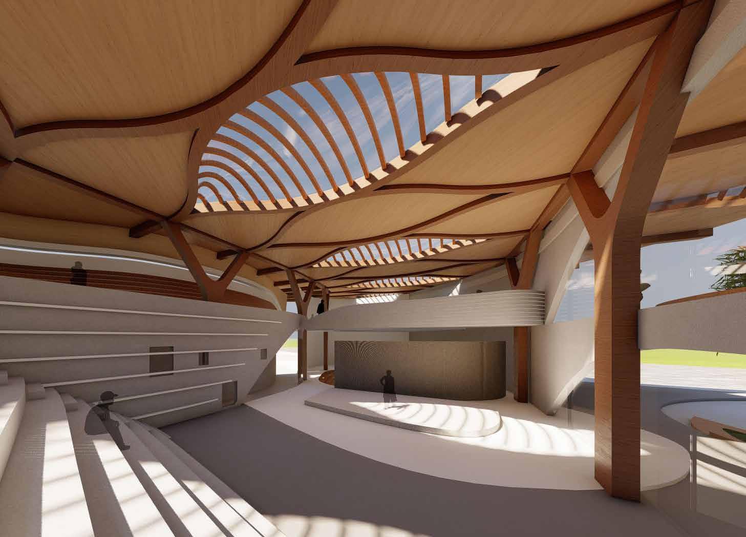
The landscape grows up to the volume, to create interstitial spaces inside the volume, which can then be occupied by programs/functions. The form flows from triangulated geometries, to unfolded surfaces, which creates interesting opportunities for daylight to embrace the volume on the interior and exterior
E S | T S|DESIGN

The from flows along the roof to wall and creates a nice opening in the roof structure towards the river side .Town hall is the major function of the building so I created a two separate from in order to connect them towards the centre of the building .then I started creating opening in the roof and the wall to create intresting form .
FIRST LIGHT E S | P S | S|DESIGN

13 Spatial Quality Extraction Initial Research

14 FORM GENERATION FLOOR
WALLLANDSCAPEPLATEANDGLASS
STRUCTURE ROOF STRUCTURE E S | P S | T S|DESIGN
SITE E S | P S | S|DESIGN


16 CLIENT USER PRIVATE TOWN HALL YOUTH CENTER LIBRARY AND EXHIBITION SPACE PUBLICStudents
The main user of the building is the office space and assembly area .in this space mostly paper works and meeting room should be provided .assembly hall could be a main intreaction space in between the office sapce and other public spaces in the building funding for the building is provided by the government funding beacause .the age group of the private space is mostly 25-50 the age group of the space is mostly 18-25 the age group of the space is mostly 18-50 The user group for library is mostly for education user and graduate . In both cases the users are en couraged to learn to become autonomous, and choose their own career paths. the main additional propsal for the students is youth center where they can communicate each other .the space could be for reading ,communicate with other students ,lecture ,diccusion ,acitivty area ,display area and major connection with the town hall helps to direct communication of the government with the students
P S | DESIGN


17 SITE IMAGES Hackney E S | T S|DESIGN


18 E S | P S | S|DESIGN Public Access Traffic Analysing Access to the site in all direction railway line station Pedestrian bus stop Car Site conditions entrance along the road acces towards north side with connect both site and pedestrian


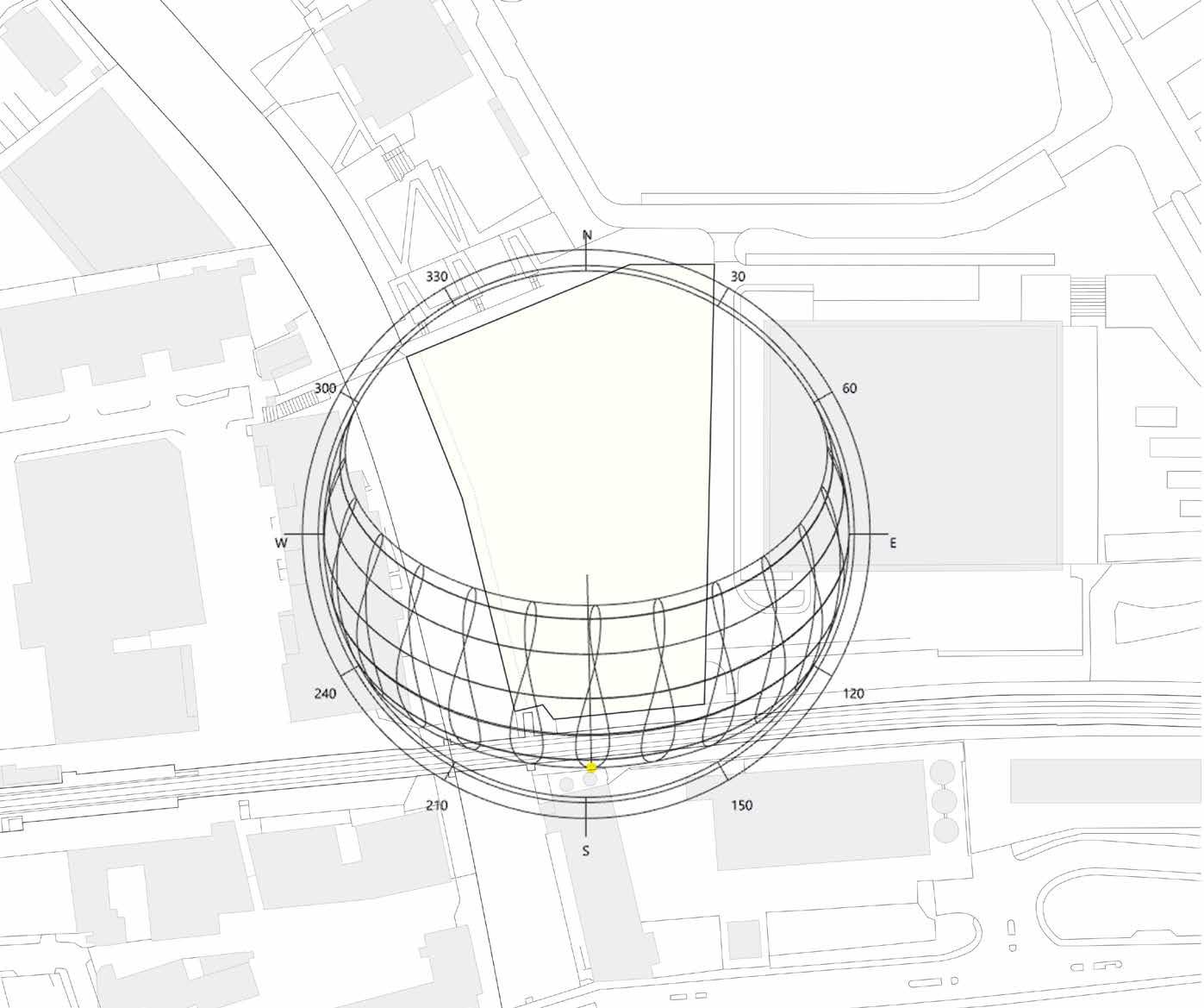
19SITE ANALYSIS SUN PATH
20 SITE ANALYSIS E S | P S | T S|DESIGN Noise Pollution

21 E S | P S | S|DESIGN Pedestrian and cycle movement MULTI DIRECTIONAL HIERARCHY
22 MASSING STRATEGIES E S |DESIGN
23 PROGRAMS TOWN HALL LIBRARY CAFE YOUTH CENTRE SPORT AREARECREATIONAL SPACEEXHIBITIONAREA
Assembly HallExhibition and youth centre Town Hall Town Hall Library Public Public Private PrivatePrivate 02 04 01 01 03 PROGRAMMATIC DIAGRAM E S | T S|DESIGN

PROPOSED MASTER PLAN SCALE DESIGN DEVELOPMENT E S | P S | S|DESIGN 0 20m100m 20m 40m 60m 80m 1:1000 2m0 2m 4m6m 8m 10m 1:100 0 0.5m0.5m 1m1.5m 2m 2.5m 1:25

28 E S | P S | S|DESIGN LOWER GROUND FLOOR PLAN LEGEND2.RECEPTION1.ENTRY3.STAFFROOM4.ADMINISTRATIVE5.LIBRARY6.LIFT7.POWERROOM8.MALETOILET9.FEMALETOILET10.READINGZONE11.ASSEMBLYHALL12.OUTDOORSEATING AREA 1 6 2 11 12 12 9 8 10 7 5 4 3

29 GROUND FLOOR PLAN LEGEND2.RECEPTION1.ENTRY3.CAFE4.ASSEMBLYHALL5.OFFICE6.PANTRY7.TOILET8.LIBRARY9.OUTDOORSEATING10.READINGZONE11.EXHIBITIONSPACE12.POWERROOM 1 2 3 8 10 11 7 7 129 9 4 2 5 5 6 7

30 FIRST FLOOR PLAN LEGEND2.RECEPTIONS1.ENTRY3.HIGHEROFFICER ROOM 10.DOCUMENTATION9.STORE8.MEETING7.6.TOILET5.PANTRY4.ADMINISTRATIVEOPENOFFICEROOMROOM ROOM 11.MANAGER ROOM 12.FIRE ESCAPE ROUTE 1 2 73 7 7 12 12 11 10 89 4 5 6

E S | P S | T S|DESIGN CIRCULATIONPUBLICPRIVATE
32E S | P S | S|DESIGN Elevation Town hall

33E S | P S | T S|DESIGN SECTION A A’ SCALE1:1000 2m0 2m 4m6m 8m 10m 1:100 0 0.5m0.5m 1m1.5m 2m 2.5m 1:25

34 TIMBER PROCESS Environmental Strategy.
Transportation process
Recycled wood From the sustainable managed forest trees are felled and prepared for the transport by removing the leaves and branches to the factory .Then trees are categories into grade A,or Grade B.and then they are processed into high quality timber products
Manufacturing of timber products. Timber are transported to the near by fac tory for the processing the timber Plywood wood to CLT
With the help of Computerized Numerical Control (CNC) milling, It is possible for each Cross-laminated panels (CLT) to obtain the Desired shape in 3-dimension, which allows for a faster and more Precise method to get complex forms in a planar orientation. Along with this Glulam Beams are also CNC milled to get the Desired joinery. CNC Milling CLT panels. Lamination. The process of manufacturing timber which helps to remove bark removal ,cutting to get veneers an sanding to produce plywood Individual plywoods boards ,with the direction of grains perpendicular to each other for each overlapping layer of boards are gathered and arranged to be cnc milled .so that why it provide strength . cnc milled planar panels are stacked on top of each other and laminated us ing a bio-based glue ,in order to secure the thickness and structural stability .


E S | P S | T S|DESIGN Technical Fragment.

E S | P S | T S|DESIGN Chunk Model The technical chunk shows, how the primary structure for the permanent roof, accommodates the structure required to support the flooring and how these loads are transferred into the foundation slab; resulting in a tectonically resolved composite structure. The thickness of the primary structures allows for services to be embedded between floor and cieling Technical Fragment.

37E S | P S | T S|DESIGN 5.0 CM CLADDING 45cm INSTALLATIONGLULAM LAYER BRACES 20 cm THERMAL INSULATION 20 CM 0.5 cm Waterproofing 5.0cm CONSTRUCTION SLAT 5.0cm ZINC CLADDING SANDEARTH FILLING .05cm WATER PROOFING 80 cm FLOORINGINSULATIONWATERPROOFINGCLTGLULAMINSULATIONCEILINGWOODENINSTALLATIONCONCRETEINSULATIONLAYERFLOORINGBEAMFLOORING DETAIL SECTION B B’ 0 0.5m0.5m 1m1.5m 2m 2.5m 1:25

E S | S|DESIGN
Tectonic Fragment.
The structural load from the roof and floor in between are transferred Onto the primary structural member and received by the concrete footing. The inverted Glulam beam (60cmX40cm), and glulam cross beams (40cmX20cm) which are fastened onto the primary structure with metal Profiles and bolts reduces the repetitive use of concrete footing and Increases the visual connectivity in the space.

40E S | P S | S|DESIGN
Tectonic Fragment. Structural build-up
The structure is made of prefabricated CLT panels, which are individually CNC Milled to achieve the form and when combined together form an intricate splice joint. Each part is prefabricated to transportable sizes and assembled on site. Each aggregation is strategically craned into position, after the metal plate is fixed onto the concrete footing. The aggregation is then bolted onto the metal plate using a double bolting system. This method of construction proves to be faster, precise and creates less timber waste.

E S | S|DESIGN Tectonic Fragment. Timber connection L jointL joint y-joint t-joint x-jointt-joint bendedsmallt-jointx-joint flat corner

Structural Axonometic View

services routes Heating cycle Hot water cycle Grey water cycle E S | T S|DESIGN
44 E S | T S|DESIGN RAIN WATER COLLECTION ENVIRONMENTAL STUDIES FS RTFSRTRAIN WATER COLLECTION Filter Rainwatersystemtank


45 Environmental studies SUN PATH AND AIR CIRCULATION FAN COIL UNIT HVAC DUCT SUN AT SUMMER 58 DEGREE SUN AT WINTER 13 DEGREE NORTH LIGHTING E S | S|DESIGN

46 N S E S | P S | T S|DESIGN Environmental studies

E S | P S | T S|DESIGN FIRE ESCAPE ROUTES REFUGE POINT FIRE HYDRANT FIRE ESCAPE FIRE EXTINGUISHER FIRE HOSE


48E S | P S | T S|DESIGN CONSTRUCTION PROCESS STEP 1 CONCRETE BASE WITH METAL PLATE WHICH SUPPORTS THE TIMBER NEXT STEP TO FIX THE CNC GLULAMB TIMBER WITH METAL PLATE ON CONCRETE FLOORINGSTEP 2


49E S | P S | S|DESIGN STEP 2 STEP 3 STEP 4 CONSTRUCTION PROCESS WOODEN FLOORING FIXING BEAM AND COLUMN


50E S | P S | T S|DESIGN STEP 5 STEP 6 CONSTRUCTION PROCESS FIRST FLOOR PLATE ABOVE PRIMARY STRUCTURE


51E S | P S | T S|DESIGN STEP 7 STEP 8 CONSTRUCTION PROCESS LAYING OF ROOF BEAM ALONF PRIMARY STRUCTURE LAYING OF SECONDARY STRUCTURE OF FACADE AND ROOF


52 STEP 9 STEP 10 CONSTRUCTION PROCESS FACADE AND INTERIOR WALL ROOF COVERING AND STAIRCASE OD STABILITY


