10 minute read
CREATIVE THINKING Award Winning Jobs Showcase Unique Use of Equipment


In Part Two of a Two Part Series, SEAA congratulates the winners of its 2023 Project of the Year competition. These two projects featured unique solutions that enabled work to be completed with minimal disruption to the public. In both cases the erectors worked closely with the general contractor, engineers of record, and other experts to collaborate on efficient, workable erection plans.
Read on to learn about creative uses of equipment, including a modular heavy haul trailer, engineered beam brace, roll and rail systems, and a roof-mounted crawler crane.
SEAA members can submit for the Project of the Year in multiple contract levels in two categories—Structural and Miscellaneous Metals
■ Reducing Road Rage
Consistently topping lists of the worst traffic in the country, I-66 cuts through the Virginia suburbs of Washington, D.C. In 2016 the Commonwealth of Virginia entered a Public-Private Partnership with I66 Express Mobility Partners for the $3.7 Billion Transform 66 project. Some of the improvements included 22.5 miles of Express Lanes and interchange improvements to enhance safety and reduce congestion.
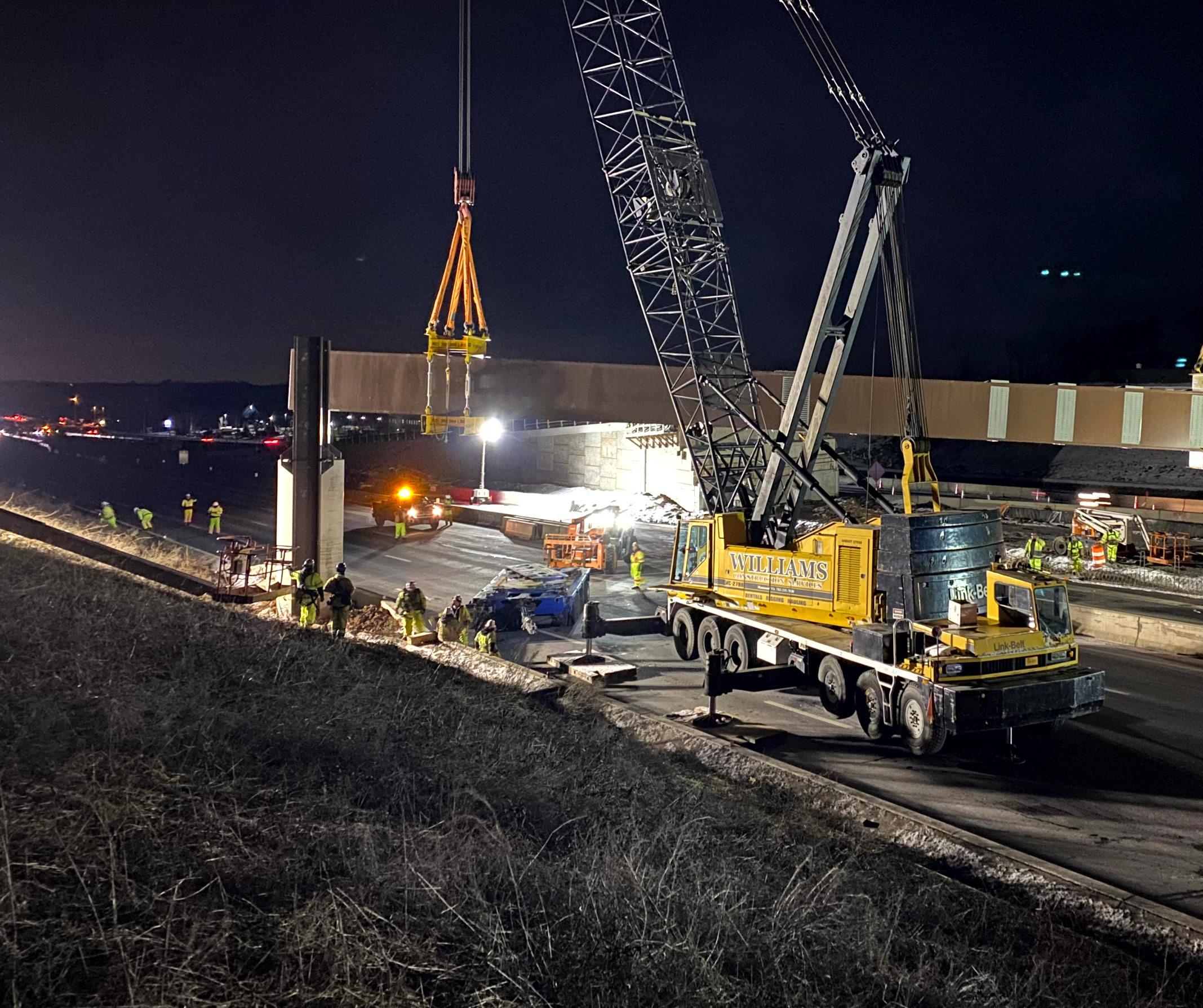
Erecting 10 flyover bridges, which carried exit ramps from central toll lanes, was one of the project’s challenges. These bridges straddled all existing lanes, requiring the bridges to be constructed during six-hour nightly closures. Compounding matters, conventional shoring for supporting the partially complete bridge structures was not possible with such tight timeframes. An innovative solution was needed.
FAM Construction, LLC the GC, which had previously contracted Williams Construction Services as the exclusive crane rental provider, asked Williams Steel Erection Co., Inc. to consult on the best way to erect the bridges.
Material delays meant that much of the work to erect the flyover bridges piled up and had to be completed simultaneously to keep the project on schedule. Ultimately, six of the 10 bridges were completed within four months (April 2022 to July 2022). To support this operation, Williams crews additionally performed the complete steel erection scope for three of the 10 bridges as well moving and erecting the box girders for all the bridges.
Unconventional solution
The complex structures like the ones on this project would typically involve significant shoring to support the partially erected structure until it was complete. This was not feasible because there was no space to place shoring that would not obstruct traffic.
The other conventional erection method would be to make a multi-crane pick, which also was not feasible in the allowable working time frame. Within a six-hour window at night, all equipment had to be set up, the operation completed, and all equipment removed before traffic lanes were reopened in the morning. Complex multiple picks could not easily be completed in such a short window and if anything went wrong and delayed the work during a shift, six-figure liquidated damages would be levied on the contractor for even slight overages in time.
Plus, the large size of the box girders (up to 250 tons each) was a challenge unto itself.
The solution involved pre-assembling the main supporting box girders for the bridges adjacent to the site and then moving them into place with Williams’ Goldhofer modular heavy haul trailer to be picked and set with cranes.
Initially the plan called for 1,000 bolts per slice, with box girders arriving in two pieces. “It wasn’t practical to double pick the box girder, splice it in the air, and get it done in a six hour window. According to VDOT, we had to get half the bolts in before could cutting the crane loose. We proposed to the GC that the box girders be built on the ground on the side of the road,” said Art Williams, President.
After assembling the girders and moving them into position, the box girders were braced using a low footprint engineered brace. This clamped them to the support piers while infill girders were erected between box girders and back to the bridge piers in an alternating cantilever-fashion.
While more complex than conventional methods, this kept construction usage of the active right-of-way to a minimum. Complex splices took place away from the road and any work that did have to be done over travel lanes was able to be broken into small phases. This provided frequent “out” points at which work could be paused rather than risking having equipment in the road during morning rush hour if the operation could not be completed in time.
Three hours to spare
One end of the girder was assembled on top of the modular heavy-haul trailer with 55-degree steering of individual axles. A crane sufficient to lift one half the weight of the girder was set up near the other end of the girder during the day.
“On the night of a lift, the crane lifted the end nearest it to the supports and the trailer was used to rotate the other end of the box girder across the road, moving it into place at the base of the two columns that supported them. While the girder was being positioned, we set up a second crane at the trailer end of the box girder. This second crane picked in tandem with the first crane to set the box girder on the piers,” explained Matt Skinner, Rigging Operations Manager.
Prior to erecting the box girder, another smaller crane was used to install braces on both supporting columns with a custom brace that clamped the girder to the columns. This operation limited the equipment in the roadway to the second lift crane and the trailer. “After an initial learning curve, this entire operation from first blocking the road to reopening the road took only three hours, dramatically reducing our exposure by providing a buffer of three hours for the unexpected,” said Skinner.
“We’ve learned from doing bridges over active thoroughfares that the biggest issue is always having enough time to do the work,” said Art Williams, President. Box girders were scheduled for arrival weeks in advance so that the GC could work with authorities to move traffic around the work. We had to maintain constant communication with the GC and VDOT leading up to a girder placement. At even the hint of rain, or a car accident on the roadway, operations would be shut down,” said Williams.
“There were a lot of unique ideas employed in this project. We had a great contractor to work with. They were willing to try anything and also willing to suggest anything. It was a great relationship,” said Williams.
■ Is that a Crawler Crane on the Roof?
The Colorado Convention Center Expansion is a new event space built on top of the existing Convention Center. The 200,000 sq. ft. expansion features a ballroom, a concourse pre-function space with dramatic views of the Rocky Mountains, and a rooftop terrace. A kitchen, exhibitor access via two freight elevators, and a mezzanine level with storage and a hospitality suite provides additional functionality.
Derr & Gruenewald Construction was contracted by WW|AFCO Steel to erect the structural steel for the expansion on top of the northwest corner of the existing Colorado Convention Center. The footprint of the Colorado Convention Center Expansion Project was roughly 500’ x 600’ with about 9,000 tons of steel.
“Compared to other projects Derr & Gruenewald Construction has erected, this isn’t a large footprint, but the struggle was the location on top of an existing structure,” said Ezra Presley, Project Manager. Two tower cranes were used on the project, each with a radius of 262 feet. These cranes were only able to reach two-thirds of the structure, leaving the southern third of the structure outside the reach of the tower cranes.
In addition to the tower cranes lacking the reach needed, they didn’t have the capacity. The structural design required trusses to span 90’ from existing column to existing column. On average, the primary 90’ floor trusses weighed close to 100,000 pounds (50 tons). The larger of the two tower cranes could lift one third of one of the floor trusses at a radius of 80’.
Derr and Gruenewald Construction, along with erection engineering firm Hassett Engineering, developed a plan to assemble and operate a crawler crane on the roof of the existing structure. A Liebherr LR 1300 crawler crane was selected.
It was determined that the maximum pick would be approximately 150,000 pounds and the maximum radius was 120 feet. To make these lifts, the LR1300 was configured with an optional derrick with suspended counterweight tray of 252,460 lbs. It was also equipped with a 272-foot boom, which was able to disconnect the counterweight tray and set it aside after lifting the trusses. The crane weighed 1 million pounds.
Making operations even more complex was the location of the project on the front range of the Colorado Rockies. Wind, snow, and lightning were constant risks. “Winds coming off the mountains make operating cranes a challenge most of the year. Denver averages more than 50 inches of snow annually, and Colorado ranks 19th in nation for cloud-to-ground lightning strikes. “This along with high wind speeds, made steel erection a challenge,” said Presley.
Rooftop power lifter
So how can a 1-million pound piece of equipment crawl over the roof of a convention center? Hassett Engineering worked with the project engineer of record, Martin & Martin, to analyze and verify that the structure would support the crane.
The existing convention center roof framing consisted of a joist and truss girder system with 90 ft. wide bays supported by 36” diameter unfilled pipe columns, designed only for code level snow and live loads. Martin & Martin specified that the columns be filled with concrete to support the new multi-function roof and floor, which was framed by extending the pipe columns and adding trusses above the existing roof.
“Regarding the support from the columns, we did the original work on this building in 2003. We went back and pulled the caps, and filled the columns with 75 feet of rebar and concrete,” explained CD Gruenewald, President.
At each bay, the LR1300 crane was used to build a new floor above the existing roof, capable of supporting the crane itself. After completion of steel erection and slab placement of each successive bay in the crane path, the crane would roll onto the newly constructed bay and continue erecting adjacent bays. “The tracks of the crane had to be centered on the line with no more than 2 inches in deviation either way at all times— it was a very challenging operation,” said Gruenewald.
Of course, heavier trusses were required for crane loading. Increasing the supporting truss weights resulted in more counterweight needed for the crane. Iterations produced increasingly heavy trusses, so bridging trusses at third spans of the trusses were redesigned to act continuously, transferring moments across the bridging truss/ infill truss intersections. Two-way truss action resulted in lighter trusses with overall truss weights more balanced.
Truss analysis and redesign was a very intensive process whereby the structural engineering firm considered countless possible crane locations with varying crawler pressures and partially erected support structure configurations.
“We worked with Martin & Martin on a solution for 10 months before erecting the crane on the roof. I give our guys in the field the credit for making the plan work,” said Presley.
Creative truss transport
With little room for unloading, storage and shakeout, Derr & Gruenewald ultimately used newly erected floor space as the laydown area.
“Originally, we had discussed using a transporter and building a second grillage path to transport truss members and other steel members out to the crane,” said Presley. However, the tower crane was not capable of lifting the truss sections and placing them near the crawler because they were too far apart.
“We ended up landing on a rail system with Hilman rollers and structural steel frame to move structural pieces. The Hilman rollers rolled on wide flange tracks that were aligned with the crane crawler path. The tower crane was used at the perimeter of the building and the tug pulled frames on the rollers out to the crawler crane once truss sections were assembled,” he added.