—
Brochure
ABB Micro and Machinery Drives
— Little big drives without limiting your business
ta b l e o f c o n t e n t s
3
— Table of contents
004
Introducing ABB micro and machinery drives
Choosing the right drive for your application
005
ABB Micro Drives
ACS150, 0.37kW to 4kW
009
ABB Machinery Drive
009-012
ACS355, 0.37kW to 22kW
013-016
ACS380, 0.37kW to 22kW
017
ACS380 for Cranes
018
Drive Selection Table
4
ABB Micro and Machine ry Drives , brochure
A B B mic r o a n d M ac h i n e r y D r i v e s
5
— Introducing ABB micro and machinery drives ABB micro drives Precise speed control and simple integration. ABB micro drives are suitable for many low power applications such as pumps, fans, and conveyors. Designed to be integrated into your machinery, they offer flexible mounting alternatives and straightforward setup with simple user interfaces and tools.
ABB machinery drives Premium motor control with hardware flexibility. ABB machinery drives can be configured to meet the precise needs of industry with a wide power and voltage range and both standard and optional features, including integrated safety and ready-made control programs for different applications.Worldwide availability through logistical distributors
Choosing the right drive for your application Step
Process
Action
1
Identify the application Identify the type of application and the likely demands of the drive.
Continue to step 2.
2
Understand the load. System inertia, required acceleration and deceleration rates, minimum and maximum speeds, overload requirements, etc. This information can often be determined by the performance of the existing motor.
Continue to step 3.
Gather the motor nameplate data. Power, Voltage, Current, Frequency(Hz), RPM, Insulation Class, etc.
Continue to step 4.
4
Choose a drive Match the data gathered in Steps 1 to 3 against the table of drive features. Select a drive that meets the motor requirements and has all the software features needed for the application.
Continue to step 5.
5
Is the drive offered in the correct hp/amp rating? The drive you choose must be able to supply the necessary current to the motor to produce the torque required. This includes normal and overload conditions. See selection table on page 17.
If yes, continue to step 6. If no, go to step 4.
Is the drive offered in the correct enclosure and environmental ratings? The drive you choose must be available in an enclosure style that will withstand the application’s environment. It also must produce the required current at the application’s altitude and ambient temperature. See selection table on page 17.
If yes, continue to step 7. If no, go to step 4.
Does this drive have the features needed to meet the application’s demands? The drive you choose must have a feature set that matches the application. It also must have sufficient hardware (inputs and outputs, feedback, communications, etc.) to perform the application.See selection table on page 17.
If yes, continue to step 8. If no, go to step 4.
Does this drive have the features needed to meet the application’s demands? The drive you choose must have a feature set that matches the application. It also must have sufficient hardware (inputs and outputs, feedback, communications, etc.) to perform the application. See selection table on page 17.
If yes, continue to step 9. If no, go to step 4.
3
6
7
8
9
Congratulations! The ABB AC drive you have chosen has the features and performance needed for a successful application.
6
ABB Micro and Machine ry Drives , brochure
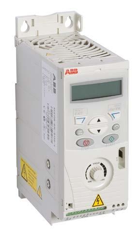
— ABB Micro Drives ACS150, 0.37kW to 4kW ACS150 0.37 kW to 4 kW • 1-phase, 200 to 240 V : 0.37kW to 2.2 kW • 3-phase, 200 to 240 V : 0.37kW to 2.2 kW • 3-phase, 380 to 480 V : 0.37kW to 4 kW Introduction ABB micro drives are designed to be incorporated into a wide variety of machines such as mixers, conveyors, fans or pumps or anywhere where a fixed speed motor needs to go variable speed motor. The ABB micro drives meet the requirements of OEMs, machinery builders and panel builders. These drives are widely available through the ABB distribution network. The drives are easy to select and provide a range of built-in features as standard including PID control, brake chopper, fixed keypad and speed control potentiometer. Features • IP20 enclosure (UL open type) • Optional NEMA 1 kit • For basic machinery applications • Scalar control • Integrated user interface and potentiometer • Built-in brake chopper • Built-in C3 EMC filter • Options • External C2 EMC filter • Input and output chokes • Flash Drop tool for unpowered drive configuration in 2 seconds
Highlights • User-friendly LCD control panel and integrated potentiometer • Flexible mounting alternatives • PID control • Integrated EMC filter • Built-in brake chopper • FlashDrop tool for fast drive commissioning • Worldwide availability through logistical distributors
ABB MICRO DRIVES ACS150, 0.37kW to 4kW
7
— Feature Table Feature
Advantage
Benefit
Worldwide availability and service
Drives are available worldwide and permanently stocked in four regions. Dedicated global service and support network that is one of the widest in the industry.
Fast and reliable delivery with dedicated support to any country in the world.
User-friendly LCD control panel and integrated potentiometer
Clear alphanumeric display. Easy setup and use.
Time savings due to quick setup and simple configuration.
Flexible mounting alternatives
Screw or DIN rail mounting, sideways or side-by-side.
One drive type can be used in various designs, saving installation costs & time.
Integrated EMC filter
High electromagnetic compatibility.
Low EMC emissions in selected environments.
Built-in brake chopper as standard
No need for an external brake chopper.
Space savings, reduced installation cost.
FlashDrop tool
Faster and easier drive setup and commissioning for volume manufacturing and maintenance. The FlashDrop tool enables both downloading and uploading drive parameters.
Fast, safe and trouble-free parameter setting without the need to power-up the drive. Patented.
PID control
Varies the drive’s performance according to the need of the application.
Enhances production output, stability and accuracy.
Coated boards
Board coating protects the electronics from hazards including static discharge and airborne contaminates, including moisture.
Reduces maintenance due to good protection of electronics components.
Type designation In column 4 on the right is the unique reference number that clearly indentifies your drive by power rating and frame size. Once you have selected the type designation, the frame size (column 5) can be used to determine the drives dimensions, shown below. Voltages ACS150 is available in two voltage ranges: 2 = 200 to 240 V 4 = 380 to 480 V Insert either “2” or “4”, depending on your chosen voltage, into the type designation shown on the right. Construction “01X” and “03X” within the type designation varies depending on the drive phase and EMC filtering. Choose below the one you need. 01 = 1-phase 03 = 3-phase E = EMC filter connected, 50 Hz frequency U = EMC filter disconnected, 60 Hz frequency (In case the filter is required it can easily be connected.)
Ratings PN kW
Type designation PN hp
Frame size
I2N A
1-phase AC supply, 200 to 240 V 0.37
0.5
2.4
ACS150-01X-02A4-2
R0
0.75
1
4.7
ACS150-01X-04A7-2
R1
1.1
1.5
6.7
ACS150-01X-06A7-2
R1
1.5
2
7.5
ACS150-01X-07A5-2
R2
2.2
3
9.8
ACS150-01X-09A8-2
R2
3-phase AC supply, 200 to 240 V 0.37
0.5
2.4
ACS150-03X-02A4-2
R0
0.55
0.75
3.5
ACS150-03X-03A5-2
R0
0.75
1
4.7
ACS150-03X-04A7-2
R1
1.1
1.5
6.7
ACS150-03X-06A7-2
R1
1.5
2
7.5
ACS150-03X-07A5-2
R1
2.2
3
9.8
ACS150-03X-09A8-2
R2
3-phase AC supply, 380 to 480 V 0.37
0.5
1.2
ACS150-03X-01A2-4
R0
0.55
0.75
1.9
ACS150-03X-01A9-4
R0
0.75
1
2.4
ACS150-03X-02A4-4
R1
1.1
1.5
3.3
ACS150-03X-03A3-4
R1
1.5
2
4.1
ACS150-03X-04A1-4
R1
2.2
3
5.6
ACS150-03X-05A6-4
R1
3
4
7.3
ACS150-03X-07A3-4
R1
4
5
8.8
ACS150-03X-08A8-4
R1
X within the type code stands for E or U.
8
ABB Micro and Machine ry Drives BROCHURE
— Cabinet-mounted drives (UL open) Frame size
IP20 UL open H1
H2
H3
W
D
Weight
mm
mm
mm
mm
mm
kg
R0
169
202
239
70
142
1.1
R1
169
202
239
70
142
1.3
R2
169
202
239
105
142
1.5
H1 H2 H3
H1 = Height without fastenings and clamping plate. H2 = Height with fastenings but without clamping plate. H3 = Height with fastenings and clamping plate. W = Width D = Depth
D
W
— Wall-mounted drives (NEMA 1) Frame size
NEMA 1 H4
H5
W
D
Weight
mm
mm
mm
mm
kg
R0
257
280
70
142
1.5
R1
257
280
70
142
1.7
R2
257
282
105
142
1.9
H4 H5
H4 = Height with fastenings and NEMA 1 connection box. H5 = Height with fastenings, NEMA 1 connection box and hood. W = Width D = Depth
D W
A B B M achine r y D r ives , t e c h n i ca l d ata
9
— Technical Data Mains connection Voltage and power range
Frequency
Programmable control connections 1-phase, 200 to 240 V ± 10% 0.37 to 2.2 kW (0.5 to 3 hp) 3-phase, 200 to 240 V ± 10% 0.37 to 2.2 kW (0.5 to 3 hp) 3-phase, 380 to 480 V ± 10% 0.37 to 4 kW (0.5 to 5 hp) 48 to 63 Hz
Motor connection Voltage
3-phase, from 0 to Usupply
Frequency
0 to 500 Hz
Continuous loading capability (constant torque at a max. ambient temperature of 40 ºC)
Rated output current I2N
Overload capability (at a max. ambient temperature of 40 ºC)
At heavy duty use 1.5 x I2N for 1 minute every 10 minutes At start 1.8 x I2N for 2 s
Switching frequency Default Selectable
4 kHz 4 to 16 kHz with 4 kHz steps
Acceleration time
0.1 to 1800 s
Deceleration time
0.1 to 1800 s
Braking
Built-in brake chopper as standard
Motor control method
Scalar U/f
Environmental limits Ambient temperature
-10 to 40 ºC (14 to 104 ºF), no frost allowed, 50 ºC (122 ºF) with 10% derating
Altitude Output current
Rated current available at 0 to 1000 m (0 to 3281 ft) reduced by 1% per 100 m (328 ft) over 1000 to 2000 m (3281 to 6562 ft)
Relative humidity
Lower than 95% (without condensation)
Degree of protection
IP20/Optional NEMA 1 enclosure
Enclosure colour
NCS 1502-Y, RAL 9002, PMS 420 C
Contamination levels
IEC 721-3-3 No conductive dust allowed Class 1C2 (chemical gases) Class 1S2 (solid particles) Class 2C2 (chemical gases) Class 2S2 (solid particles) Class 3C2 (chemical gases) Class 3S2 (solid particles)
Transportation Storage Operation Chokes AC input chokes
External option. For re duc ing THD in partial loads and to comply with EN 61000-3-2.
AC output chokes
External option. To achieve longer motor cables.
One analog input Voltage signal Current signal Potentiometer reference value Resolution Accuracy
0 (2) to 10 V, Rin > 312 kΩ 0 (4) to 20 mA, Rin = 100 Ω 10 V ± 1% max. 10 mA, R < 10 kΩ 0.1% ± 2%
Auxiliary voltage
24 V DC ± 10%, max. 200 mA
Five digital inputs
12 to 24 V DC with internal or external supply, PNP and NPN, pulse train 0 to 16 kHz
Input impedance
2.4 kΩ
One relay output Type Maximum switching voltage Maximum switching current Maximum continuous current
NO + NC 250 V AC/30 V DC 0.5 A/30 V DC; 5 A/230 V AC 2 A rms
Product compliance Low voltage Directive 2006/95/EC with supplements Machinery Directive 2006/42/EC EMC Directive 2004/108/EC with supplements Quality assurance system ISO 9001 Environmental system ISO 14001 UL, cUL, CE, C-Tick and GOST R approvals RoHS compliant
10
ABB Micro and Machine ry Drives , brochure
— ABB Machinery Drives ACS355, 0.37kW to 22kW ACS355 0.37 kW to 22 kW • 1-phase, 200 to 240 V : 0.37kW to 2.2 kW • 3 -phase, 200 to 240 V : 0.37kW to 11 kW • 3 -phase, 380 to 480 V : 0.37kW to 22 kW Introduction The ABB machinery drives are designed to be fast drives to install,parameter-set and commission. Thus saving hours of engineering work.They are highly compact and cost effective and equipped with cutting edge intelligence and an innovative safety capability. The drives are designed specifically to meet the production and performance needs of system integrators, original equipment manufacturers (OEMs) and panel builders, as well as the requirements of end users in a broadrange of applications. Features • Power range 0.37 to 22 kW (3-phase 380 to 480 V) • IP20 enclosure (UL open type), optional NEMA 1 kit • IP66, IP67 or IP69K (Nema 4X) as optional variant up to 7.5 kW • Advanced functionality with sequence programming • Scalar control, open and closed loop vector control • Induction and permanent magnet motor control • Built-in brake chopper and C3 EMC filter • Integrated safe torque off (STO) as standard • Product variants include solar pump drive, high speed application,and enhanced sequence programming • Basic and assistant control panels • Potentiometer, plug-in fieldbus adapters, encoder interface, relayoutput extension module, input and output chokes • External EMC filter for 1st environment • FlashDrop tool for unpowered drive configuration in 2 seconds
Highlights • Exceptionally compact drives and uniform design • Quick commissioning with application macros and panel assistants • Safe torque off function (SIL3) as standard • Sensorless vector control for induction motors and permanent magnet motors up to 599 Hz • Built-in braking chopper • IP66 product variant for harsh environments and solar pump drive variant available
11
A B B M achine r y D r ives , A C S 3 5 5 , 0 . 3 7 k W to 2 2 k W
— Order Data ACS355-03E-02A4 - 2 Type designation This is the unique reference number (shown above and in column 4, right) that clearly identifies your drive by current rating and frame size. Once the drive’s type designation has been selected, the frame size (column 5) can be used to determine the drive dimensions, shown on page 10. Voltages ACS355 is available in two voltage ranges: 2 = 200 to 240 V 4 = 380 to 480 V Insert either “2” or “4”, depending on your chosen construction, current rating, voltage, and option and variant codes into the type designation shown above. Variant code This code states the factory installed SW variants to the drive. Construction “01E” within the type designation (shown above) varies depending on the drive phase and EMC filtering. Choose below the one you need. 01 = 1-phase 03 = 3-phase E = EMC filter connected, 50 Hz frequency U = EMC filter disconnected, 60 Hz frequency (In case the fi lter is required it can easily be connected)
Ratings IP20/UL Open type/ NEMA 1 option PN [kW]
PN [hp]
I2N [A]
Type designation
Frame size IP20
Frame size IP66
1-phase AC supply, 200 to 240 V +B063 0.37
0.5
2.4
ACS355-01X-02A4-2
R0
-
0.75
1.0
4.7
ACS355-01X-04A7-2
R1
-
1.1
1.5
6.7
ACS355-01X-06A7-2
R1
-
1.5
2.0
7.5
ACS355-01X-07A5-2
R2
-
2.2
3.0
9.8
ACS355-01X-09A8-2
R2
-
3-phase AC supply, 200 to 240 V +B063 0.37
0.5
2.4
ACS355-03X-02A4-2
R0
R1
0.55
0.75
3.5
ACS355-03X-03A5-2
R0
R1
0.75
1.0
4.7
ACS355-03X-04A7-2
R1
R1
1.1
1.5
6.7
ACS355-03X-06A7-2
R1
R1
1.5
2.0
7.5
ACS355-03X-07A5-2
R1
R1
2.2
3.0
9.8
ACS355-03X-09A8-2
R2
R3
3.0
3.0
13.3
ACS355-03X-13A3-2
R2
R3
4.0
5.0
17.6
ACS355-03X-17A6-2
R2
R3
5.5
7.5
24.4
ACS355-03X-24A4-2
R3
-
7.5
10.0
31.0
ACS355-03X-31A0-2
R4
-
11.0
15.0
46.2
ACS355-03X-46A2-2
R4
-
3-phase AC supply, 380 to 480 V +B063 0.37
0.5
1.2
ACS355-03X-01A2-4
R0
R1
0.55
0.75
1.9
ACS355-03X-01A9-4
R0
R1
0.75
1.0
2.4
ACS355-03X-02A4-4
R1
R1
1.1
1.5
3.3
ACS355-03X-03A3-4
R1
R1
1.5
2.0
4.1
ACS355-03X-04A1-4
R1
R1
2.2
3.0
5.6
ACS355-03X-05A6-4
R1
R1
3.0
3.0
7.3
ACS355-03X-07A3-4
R1
R1
4.0
5.0
8.8
ACS355-03X-08A8-4
R1
R1
5.5
7.5
12.5
ACS355-03X-12A5-4
R3
R3
7.5
10.0
15.6
ACS355-03X-15A6-4
R3
R3
11.0
15.0
23.1
ACS355-03X-23A1-4
R3
-
15.0
20.0
31.0
ACS355-03X-31A0-4
R4
-
18.5
25.0
38.0
ACS355-03X-38A0-4
R4
-
22.0
30.0
44.0
ACS355-03X-44A0-4
R4
-
X within the type designation stands for E or U. PN for kW = Typical motor power in 400 V at normal use PN for hp = Typical motor power in 460 V at normal use I2N for A = Continuous rms current. 50% overload is allowed for one minute in ten minutes.
12
ABB Micro and Machine ry Drives BROCHURE
— Dimension Cabinet-mounted drives (IP20/UL Open) Frame size
IP20/UL Open H1 mm
H2 mm
H3 mm
W mm
D1 mm
D2 mm
Weight kg
R0
169
202
239
70
161
187
1.2
R1
169
202
239
70
161
187
1.2
R2
169
202
239
105
165
191
1.5
R3
169
202
236
169
169
195
2.5
R4
181
202
244
260
169
195
4.4
H1 H2 H3
H1 = Height without fastenings and clamping plate H2 = Height with fastenings but without clamping plate H3 = Height with fastenings and clamping plate W = Width D1 = Standard depth D2 = Depth with MREL, MPOW or MTAC option
D1 D2 W
Wall-mounted drives (NEMA 1/UL Type 1) Frame size
IP20/UL Open H4 mm
H5 mm
W mm
D1 mm
D2 mm
Weight kg
R0
257
280
70
169
187
1.6
R1
257
280
70
169
187
1.6
R2
257
282
105
169
191
1.9
R3
260
299
169
177
195
3.1
R4
270
320
260
177
195
5.0
H4 H5
H4 = Height with fastenings and NEMA 1 connection box H5 = Height with fastenings, NEMA 1 connection box and hood W = Width D1 = Standard depth D2 = Depth with MREL, MPOW or MTAC option
D1 D2
W
Wall-mounted drives (IP66/IP67/UL Type 4X) Frame size
IP20/UL Open H mm
W mm
D mm
Weight kg
R1
305
195
281
7.7
R3
436
246
277
13
H
H = Height W = Width D1 = Standard depth
D1 W
A B B M achine r y D r ives , t e c h n i ca l d ata
13
— Technical Data Mains connection Voltage and power range
Frequency
Programmable control connections 1-phase, 200 to 240 V ± 10% 0.37 to 2.2 kW (0.5 to 3 hp) 3-phase, 200 to 240 V ± 10% 0.37 to 11 kW (0.5 to 15 hp) 3-phase, 380 to 480 V ± 10% 0.37 to 22 kW (0.5 to 30 hp) 48 to 63 Hz
Common DC connection Voltage and power range
230 V drives, 325 V ±15% 400/480 V drives, 540 ± 15% (common DC manual) Pmax = Pn of the drive
Motor connection Voltage
3-phase, from 0 to Usupply
Frequency
0 to 599 Hz
Continuous loading Rated output current I2N capability (constant torque at a max. ambient temperature of 40 ºC) Overload capability (at a max. ambient temperature of 40 ºC)
1.5 x I2N for 1 minute every 10 minutes At start 1.8 x I2N for 2 s
Switching frequency Selectable
Default 4 kHz 4 to 16 kHz with 4 kHz steps
Acceleration time
0.1 to 1800 s
Deceleration time
0.1 to 1800 s
Braking
Built-in brake chopper as standard
Speed control Static accuracy Dynamic accuracy
20% of motor nominal slip <1% s with 100% torque step
Torque control Torque step rise time Non-linearity
< 10 ms with nominal torque ± 5% with nominal torque
Two analog input Voltage signal Unipolar Bipolar Current signal Unipolar Bipolar Potentiometer reference value Resolution Accuracy
-10 to 40 °C (14 to 104 °F), no frost allowed 50 °C (122 °F) with 10% derating
Altitude
Rated current available at 0 to 1000 m. In altitudes from 1000 to 2000 m (3300 to 13,200 ft) above sea level, the derating is 1% for every 100 m (330 ft). If the installation site is higher than 2000 m (6600 ft) above sea level, please contact your local ABB distributor or offi ce for further information.
Relative humidity
Lower than 95% (without condensation)
Degree of protection
IP20/optional NEMA 1/UL type 1 enclosure IP66/IP67/UL Type 4X as an option up to 7.5 kW, IP69K available for IP66/IP67 variant with compatible cable glands
Enclosure colour
NCS 1502-Y, RAL 9002, PMS 420 C
Contamination levels
IEC 721-3-3 No conductive dust allowed Class 1C2 (chemical gases) Class 1S2 (solid particles) Class 2C2 (chemical gases) Class 2S2 (solid particles) Class 3C2 (chemical gases) Class 3S2 (solid particles)
Transportation Storage Operation Product compliance
Low Voltage Directive 2006/95/EC Machinery Directive 2006/42/EC EMC Directive 2004/108/EC Quality assurance system ISO 9001 En vi ron men tal sys tem ISO 14001 UL, cUL, CE, C-Tick and GOST R approvals RoHS compliant
0 (4) to 20 mA, Rin = 100 Ω -20 to 20 mA, Rin = 100 Ω 10 V ± 1% max. 10 mA, R < 10 kΩ 0.1% ± 2%
One analog output
0 (4) to 20 mA, load < 500 Ω
Auxiliary voltage
24 V DC ± 10%, max. 200 mA
Five digital inputs
Input impedance
12 to 24 V, PNP and NPN, programmable DI5 0 to 16 kHz pulse train 2.4 kΩ
One relay output Type Maximum switching voltage Maximum switching current Maximum continuous current
NO + NC 250 V AC/30 V DC 0.5 A/30 V DC; 5 A/230 V AC 2 A rms
Serial and Ethernet communication Fieldbuses Refresh rate
Plug-in type < 10 ms (between drive and fieldbus module)
DeviceNetTM
5-pin screw type connector, up to 500 kbit/s baud rate
PROFIBUS DP
9-pin D-connector, up to 12 Mbit/s baud rate
PowerLink
2 pcs RJ-45 connector, 100 Mbit/s baud rate
ControlNetTM
2 pcs 8P8C modular jacks
CANopen®
9-pin D-connector, up to 1 Mbit/s
Modbus RTU
4-pin screw type connector, up to 115 kbit/s baud rate
EtherNet/IP TM, Modbus TCP, PROFINET IO
1 RJ45 connector (FENA-01 and -11) or 2 RJ45 connectors (FENA-21). 10/100Mbit/s baud rate
LonWorks®
3-pin screw type connector, up to 78 kbit/s baud rate
EtherCAT®
2 pcs RJ-45 connectors, 100 Mbit/s baud rate
Environmental limits Ambient temperature
0 (2) to 10 V, Rin > 312 kΩ -10 to 10 V, Rin > 312 kΩ
Chokes AC input chokes
External option. For reducing THD in partial loads and to comply with EN/ IEC 61000-3-12.
AC output chokes
External option. To achieve 2x longer motor cables
14
ABB Micro and Machine ry Drives BROCHURE
— ABB Machinery Drives ACS380, 0.37kW to 22kW ACS380 0.37 kW to 22 kW • 1-phase, 200 to 240 V : 0.37kW to 2.2 kW • 3-phase, 380 to 480 V : 0.37kW to 22 kW Introduction The all-compatible machinery drives provide high performance, adaptability and dependability for machine building needs. The drives help machine builders improve machine performance and provide more added value for their customers, while simultaneously cutting integration and maintenance costs. The machinery drives are part of ABB’s allcompatible drives portfolio, offering technically compatible drives with long-term solutions and support for users, processes, business and the environment. Features • Power and voltage range: 1-phase, 0.25 to 2.2 kW, 200 to 240 V • Power and voltage range: 3-phase, 0.25 to 22 kW, 380 to 480 V • Enclosure class: IP20 • Built-in EMC filter, category C2 • Functional safety: Safe torque off (STO) as standard • Extended connectivity to I/O • Integrated control panel • Wide range of motor control (IM,PMSM,SynRM) • Pre-configured communication adapter options for faster comissioning • Extended control panel options including wireless control panel • Integrated Brake Chopper • Adaptive programing
Highlights • Preconfigured drive variant for fast installation to machines • Integrated icon based user interface for faster usability • Adaptive programming for extended application programming • Optimal application performance with vector control
15
A B B M achine r y D r ives , A C S 3 8 0 , 0 . 3 7 k W to 2 2 k W
— Ratings, types and voltages
ACS380 U N=200V(range 200to 240V).Thepower ratingsarevalid at nominal voltage 200V (0.25 to 3.0kW) Heavy duty use PHd kW
I Hd A
Maximum output current
Light overload use
Imax A
PLd kW
Nominal ratings I Ld A
PN kW
Type designation
Frame size
IN A
0.25
1.8
3.2
0.37
2.3
0.37
2.4
ACS380-04xx-02A4-1
R0
0.37
2.4
4.3
0.55
3.5
0.55
3.7
ACS380-04xx-03A7-1
R0
0.55
3.7
6.7
0.75
4.6
0.75
4.8
ACS380-04xx-04A8-1
R1
0.75
4.8
8.6
1.1
6.6
1.1
6.9
ACS380-04xx-06A9-1
R1
1.1
6.9
12.6
1.5
7.4
1.5
7.8
ACS380-04xx-07A8-1
R1
1.5
7.8
14.0
2.2
9.3
2.2
9.8
ACS380-04xx-09A8-1
R2
2.2
9.8
17.6
3.0
11.0
3.0
12.2
ACS380-04xx-12A2-1
R2
U N=400V(range 3800to 480V).Thepower ratingsarevalid at nominal voltage 400V (0.37to 22kW) Heavy duty use PHd kW
I Hd A
Maximum output current
Light overload use
Nominal ratings
Frame size
Imax A
PLd kW
PN kW
I Ld A
Type designation
IN A
0.37
1.2
2.2
0.55
1.7
0.55
1.8
ACS380-04xx-01A8-4
R0
0.55
1.8
3.2
0.75
2.5
0.75
2.6
ACS380-04xx-02A6-4
R1
0.75
2.6
4.7
1.1
3.1
1.1
3.3
ACS380-04xx-03A3-4
R1
1.1
3.3
5.9
1.5
3.8
1.5
4
ACS380-04xx-04A0-4
R1
1.5
4
7.2
2.2
5.3
2.2
5.6
ACS380-04xx-05A6-4
R1
2.2
5.6
10.1
3
6.8
3
7.2
ACS380-04xx-07A2-4
R1
3
7.2
13
4
8.9
4
9.4
ACS380-04xx-09A4-4
R1
4
9.4
16.9
5.5
12
5.5
12.6
ACS380-04xx-12A6-4
R2
5.5
12.6
22.7
7.5
16.2
7.5
17
ACS380-04xx-17A0-4
R3
7.5
17
30.6
11
23.8
11
25
ACS380-04xx-25A0-4
R3
11
25
44
15
31
15
32
ACS380-04xx-032A-4
R4
15
32
57
18.5
36
18.5
38
ACS380-04xx-038A-4
R4
18.5
38
68
22
43
22
45
ACS380-04xx-045A-4
R4
22
45
81
22
48
22
50
ACS380-04xx-050A-4
R4
Nominal ratings PN IN
Rated current available continuously without overloadability at 50 °C. Typical motor power in no-overload use.
Maximum output current Imax
Maximum output current. Available for 2 seconds at start, then as long as allowed by drive temperature.
Heavy-duty use I Hd PHd
Continuous current allowing 150% I Hd for 1 minute every 10 minutes at 50 °C. Typical motor power in heavy-duty use.
Light-overload use I Ld
Continuous current allowing 110% I Ld for 1 minute every 10 minutes at 50 °C.
PLD
Typical motor power in light-overload use.
The ratings apply at 50 °C ambient temperatures. For derating at higher altitudes, temperatures or switching frequencies, see the user's HW manual, document code: 3AXD50000029274
ABB Micro and Machine ry Drives BROCHURE
16
Universal communication with ABB fieldbus adapters The machinery drives support the following fieldbus protocols: Option code
Fieldbus protocol
Adapter
+K454
PROFIBUS DP, DPV0/DPV1
FPBA-01
+K457
CANopen®
FCAN-01
+K469
EtherCAT®
FECA-01
+K475
Two port EtherNet/IP™, Modbus TCP, PROFINET IO
FENA-21
+K470
Ethernet POWERLINK
FEPL-02
Segment ACS380
-
A
B
C
04
2
C
D -
02A6
E -
4
F +
Option codes
Product series Types and construction Rating Voltage Option code Basic codes Basic codes Segment Segment A A
Option Option Construction Construction
B
EMC filter EMC filter
C C D D E E
Connectivity Current rating Current rating Voltage rating Voltage rating 1
Description Description
04 = Module, IP20
Module, IP20 or C4 (200 V Variant), 0 = 04 C3 = (400 V variant) = C3 filtering (400 V variant) orFirst C4 (200 V Variant), 2 =0High level for environment (EN 61800-3, Class C2) environment (EN(I/O 61800-3, Class C2)C = Configured variant Connectivity 2 = High filtering level for First S = Standard variant and Modbus), S = Standard variant (I/O and Modbus), C = Configured variant For example, 02A6 refers to a nominal output current of 2.6 A For example, 02A6 refers to a nominal output current of 2.6 A 1 = 1-phase 230 V, 4 = 3-phase 380...480 V 1 = 1-phase 230 V, 4 = 3-phase 380...480 V
— Dimensions ACS380 IP20 Height
Width
Depth
Frames
mm
mm
mm
Weight kg
R0
223
70
174
1.4
R1
223
70
174
1.6
R2
223
95
174
1.9
R3
223
169
174
3.0
R4
223
260
174
5.8
H
D W
A B B M achine r y D r ives , T e c h n i ca l d ata
17
— Technical Data Functional safety
Mains connection Voltage and power range
1-phase, 200 to 240 V, +10%/-15% 0.25 to 2.2 kW 3-phase, 380 to 480 V, +10%/-15% 0.25 to 22 kW
Frequency
50/60 Hz ± 5%
Charging circuit
Environmental limits
-1 types 270 to 325 V ±10% -4 types 485 to 620 V ±10% Internal charging circuit
Transportation and storage Operation
Motor connection Voltage Frequency Motor control Switching frequency Dynamic braking
0 to UN, 3-phase 0 to 599 Hz
Cooling method Altitude
Scalar control Vector control 1 to 12 kHz, default 4 kHz Flux braking (moderate or full) Resistor braking (optional)
Motor control performance
Relative humidity
Dynamic accuracy
20% of motor rated slip 1% with 100% torque step
Speed control performance, closed loop Static accuracy Dynamic accuracy
0.1% of motor rated speed <1% with 100% torque step
Torque control performance Torque step rise time Non-linearity
< 10 ms, rated torque step ±5% with rated torque
Braking power connection Brake chopper
Built-in brake chopper as standard
Brake resistor
External resistor connected to drive
-40 to +70 °C (-40 to +158 °F) -10 to +50 °C (14 to 122 °F), with derating up to 60 °C (except R0, which has max temperature of 50 °C) Air-cooled, dry clean air 0 to 4000 m, (0 to 13000 ft) for 400 V units (see allowed power systems in HW manual) 0 to 2000 m, ( 0 to 6600 ft) for 200 V units derating above 1000 m (3300 ft) 5 to 95%, no condensation allowed
Degree of protection
IP20 as standard
Contamination levels
No conductive dust allowed
Storage
IEC 60721-3-1, Class 1C2 (chemical gases) Class 1S2 (solid particles)
Transportation
IEC 60721-3-2, Class 2C2 (chemical gases) Class 2S2 (solid particles)
Operation
IEC 60721-3-3, Class 3C2 (chemical gases) Class 3S2 (solid particles)
Speed control performance, open loop Static accuracy
Safe torque off (STO) acc. to EN/IEC61800-5-2: IEC61508 ed2: SIL 3, IEC 61511: SIL 3, IEC 62061: SIL CL 3, EN ISO 13849-1: PL e
Ambient temperature
Common DC connection DC voltage level
Built-in safety features
Product compliance CE Low Voltage Directive 2006/95/EC, EN 61800-5-1: 2007 Machinery Directive 2006/42/EC, EN 61800-5-2: 2007 EMC Directive 2004/108/EC, EN 61800-3: 2004 + A1: 2012 UL, cUL certification TUV Certification for functional safety Quality assurance system ISO 9001 Environmental system ISO 14001 Waste electrical and electronic equipment directive (WEEE) 2002/96/ EC RoHS directive 2011/65/EU EAC
18
ABB Micro and Machine ry Drives , brochure
— ACS380 for Cranes
ACS380 For Crane 0.37 kW to 22 kW • 1-phase, 200 to 240 V : 0.37kW to 2.2 kW • 3 -phase, 380 to 480 V : 0.37kW to 22 kW Features Works with following crane interfaces • Joystick • Pendant controller • Motor potentiometer • Fieldbus control Built-in crane application includes • Slowdown logic • End limit logic • Fast stop function • Mechanical brake control Robust design • Advanced cooling system • Earth fault protection based on three-phasecurrent measurement Highlights All built-in for efficient overhead and tower crane movements The drive includes built-in control for hoist, trolley and long travel/slew movements and the essential functions for typical crane applications. It works precisely both in open and closed loop configurations. Reliable operation With their coated circuit boards, 50 °C ambientrating and advanced cooling system, ACS380 drivesare made to last even in demanding atmospheres. A lot packed into a compact unit The drive includes an integrated brake chopper for dynamic braking and safe torque off (SIL 3) as standard. The drive can be installed in a crane cabinet either to a DIN rail or with a screw installation.
19
A B B M ic r o D r ives , d r i v e s e l e c t i o n ta b l e
— Drive Selection Table
Specification Voltage and power ranges
ACS150 − 1-phase, 200 to 240 V : 0.37kW to 2.2 kW − 3-phase, 200 to 240 V : 0.37kW to 2.2 kW − 3-phase, 380 to 480 V : 0.37kW to 4 kW
ACS355 − 1-phase, 200 to 240 V : 0.37kW to 2.2 kW − 3-phase, 200 to 240 V : 0.37kW to 11 kW − 3-phase, 380 to 480 V : 0.37kW to 22 kW
ACS380 − 1-phase, 200 to 240 V : 0.37kW to 2.2 kW − 3-phase, 380 to 480 V : 0.37kW to 22 kW
Protection classes UL type 0/IP20
•
•
•
UL type 1/IP21
−
o
−
UL Type 12/IP54/IP55
−
−
−
UL Type 4X/IP66/IP67
−
•1)
−
UL type 3R
−
−
−
Mounting arrangements Optimal for cabinet mounting
•
•
•
Optimal for wall mounting
o
o
−
Parameter programming
•
•
Sequence programming
−
•
−
o
Assistant control panel
−
o/•
o
Bluetooth-enabled panel
−
−
o
Programming • •
10)
Human- Machine interface Basic control panel
Integrated control panel
•
−
o
•
Motor Control
Scalar (V/Hz) selectable for linear (CT) or square function (VT)
Open loop vector, Scalar (V/ Hz) and Closed loop control
Open loop vector, Scalar (V/Hz) and Closed loop control - AC induction and PMAC motors
Ambient Temperature
14 to 104˚F (-10 to +40˚C), 122˚F (+50˚C) with derating No frost allowed.
14 to 104˚F (-10 to 40˚C), 122˚F (50˚C) with derating No frost allowed.
14 to 122˚F (-10 to 50˚C), Up to 140˚F (60˚C) with derating No frost allowed.
Inputs and outputs Digital inputs/outputs Relay outputs Analog inputs/outputs Encoder feedback
5/0
5/1
4/25)
1
1 (+3 Optional)
1 (+4 optional)
2/0
2/1
2/1
−
o
•
Supported fieldbus protocols MODBUS RTU
−
o
•
Profibus DP
−
o
o
DeviceNet TM
−
o
− −
Controlnet
−
o
CANopen
−
o
o
Ethernet IP
−
o
o
MODBUS TCP
−
o
o o
EtherCAT
−
o
Ethernet POWERLINK
−
o
o
Profinet IO
−
o
o
20
ABB Micro and Machine ry Drives , brochure
— Drive Selection Table
Specification
ACS150
ACS355
ACS380
•
•
o
EMC compliance (EN 61800-3) C3, industrial use C2, commercial use (installation by EMC experts) C1,Commercial Use
o
o
o
o (Conductive emission)
o (Conductive emission)
o
Input reactors
o
o
o
Output reactors
o
o
o
Brake chopper Suggested maximum motor cable length Switching frequency
•
•
•
30-60m
30-60m
30-60m upto 12kHz
upto 16kHz
upto 16kHz
Output frequency
0-500Hz
0-599Hz
0-599Hz
Overload capacity
150% for 60s 180% for 2s
150% for 60s 180% for 2s
150% for 60s 180% for 2s
3
7
7
−
o
•
Number of preset speeds PC tools Drive commissioning tool Drive offline programming tool
o
o
•
Drive dimensioning tool
−
−
•
UL, cUL, CE, RMS, C-Tick, EAC
•
•
•
RoHS compliance
•
•
Approvals
• Standard −Not Available
oOptional 1) IP66 Product varaint
5) DO are DIO and can be used as DI
• 10) Greater range when programmed using Drive Config software
21
— Notes
22
— Notes
ABB Micro and Machine ry Drives , brochure
23
—
For more information, please contact your local ABB representative or visit
© Copyright 2017 ABB. All rights reserved. Specifications subject to change without notice.
3AUA0000145061 REV H EN 22.6.2017 *20084
www.abb.com/ACS380 www.abb.com/drives www.abb.com/drivespartners www.abb.com/motors&generators