
POLITECNICO DI MILANO
School of Architecture Urban Planning Construction Engineering
Laurea Magistrale in Architecture - Building Architecture Academic Year 2021/2022
MILANO INNOVATION DISTRICT
Supervisor: Prof. Francesca Battisti
Co-Supervisors: Prof. Grigor Angjeliu
Prof. Giovanni Dotelli
Prof. Francesco Romano
Prof. Massimiliano Nastri
Authors: Giacomo Coviello
Selanur Demir
SPORT & RECREATION CENTER
FROM EXPO TO MIND


SOMMARIO
ABSTRACT
Standing on the eastern side of MIND (Milano Innovation District) - the rising Italian centre of scientific excellence and contemporary international district of the city - the new Recreation Centre reconfigures the park as the core of the Knowledge Hub.
As the foremost major leisure facility at this entrance to the district, the building and its pertaining outdoor areas will accommodate a wide range of sport activities, along with spaces for recreation, socialization, and interaction such as experimental, multimedia and music labs, dance halls, cinema, and theatre, addressed to the enjoyment of Mind’s community.
The design of a new 13,000-square-meter state-of-the-art Recreation Centre provides the thesis with its main field of experimentation: bringing landscape “into the foreground” to generate new urban identities, giving a radical interpretation of MIND principles and strategies which, in the current state of planning, have not yet fully expressed their potential. The site is indeed strategically selected to conclude and valorise the role of the linear public park along the Decumano. With the aim of redefining its identity inside the district, the Rec Centre is conceived as an “urban device”, a habitable
architecture and, at the same time, an urban place generating social relations and giving “response” to the integration expectations of a complex community of scientists, citizens, and city-users.
The building is configured as a continuous surface, a strip of the park that ascends while shaping clearings, promenades, and belvederes, opening up radically different prospects on the new district and capitalizing on views of city skyline. The act of “bending” the city ground to create “landscape” constitutes the generative act of the project: an artificial ground, modelled to “serve” the whole urban district, redefines the site topography with respect to the present masterplan.
The building as “landscape” provides a harmonious transition from the Hill towards the State University’s cluster, strengthening not only physical connections but also the sense of place. Based on the European concept of urban park, the project looks to the historic Milanese parks - forerunner visionaries anticipating several contemporary parks - to reinvent places where nature, architecture, and major urban functions merge into a formidable landscape.
SOMMARIO
ABSTRACT
Adagiato sul versante orientale di MIND (Milano Innovation District) - il nascente centro italiano di eccellenza scientifica e contemporaneo distretto internazionale della città - il nuovo Recreation Centre riconfigura il parco come fulcro del Knowledge Hub.
Prima importante struttura dedicata al tempo libero da questo “accesso” al distretto, l’edificio e le aree esterne di pertinenza ospiteranno un’ampia gamma di attività sportive, oltre a spazi ricreativi, per la socializzazione e l’interazione quali laboratori sperimentali, multimediali e musicali, sale per la danza, il cinema e il teatro, aperti alla fruizione della comunità di Mind.
La progettazione di un innovativo Rec Centre di 13.000 metri quadrati offre alla tesi il suo principale campo di sperimentazione: portare il paesaggio “in primo piano” per generare nuove identità urbane, offrendo un’interpretazione radicale di principi e strategie di MIND che, allo stato attuale della progettazione, non hanno ancora espresso appieno le loro potenzialità.
L’area di intervento è infatti strategicamente individuata per concludere e valorizzare il ruolo del parco pubblico lineare lungo l’asse del Decumano. Con l’obiettivo di ridefinirne l’identità all’interno del quartiere, il nuovo Rec Center
è concepito come un “dispositivo urbano”, un’architettura abitabile e, al tempo stesso, un luogo urbano capace di generare relazioni sociali e dare “risposta” alle aspettative di integrazione di una comunità complessa di scienziati, cittadini e city-user.
L’edificio si configura come una superficie continua, un lembo del parco che si erge disegnando radure, passeggiate e belvederi, aprendo prospettive radicalmente diverse sul nuovo quartiere e beneficiando degli scorci sullo skyline della città. L’atto di “piegare” il suolo urbano per generare “paesaggio” è l’atto generativo del progetto: un suolo artificiale, modellato per “servire” l’intero distretto urbano, ridefinisce la topografia del sito rispetto all’attuale masterplan.
L’edificio come “paesaggio” fornisce una transizione armoniosa dalla collina al comparto dell’Università Statale, rafforzando non solo le connessioni fisiche ma anche il senso del luogo. Fondato sul concetto europeo di parco urbano, il progetto guarda ai parchi storici milanesi - precursori visionari di molti parchi contemporanei - per reinventare luoghi in cui natura, architettura e grandi funzioni urbane si fondono in un formidabile paesaggio.


1 2 4 3 5 CONTENT
Context Innovation District Analysis
Study Design Strategies
Design
Expo
- Expo
Expo
Re-arrangement
The
Fabric
Proposed Master Plans of Mind 3 21 35 43 51 5 7 9 10 15 23 25 29 31 33 37 39 41 45 49 55 57 60 65 76 77 p. p. p. p. p. p. p. p. p. p. p. p. p. p. p. p. p. p. p.
p.
p.
Structure
Entrances and Connections
Functional Program
Topologies
Sports Complex
Design
Plans
Elevations
History of
Case
Building
01.1 - Before
01.2
01.3 - After
01.4 - MIND
of
City
01.5 -
p. p.
p. p.
p. 02.1- MIND in the City
02.2-
02.3- Greenery in MIND 02.4-
of MIND 02.5- MIND
04.1- Hangzhou Cloud Exhibition Centre 04.2- Changchun Community
03.1- Location of Proposed
03.2- Volume Schemes 03.3- Building Program 05.1- Master Plan 05.2- Green Roof and Skylights 05.3- Manifesto Section 05.4- Floor
05.5- Sections 05.6- Facade Concept &
Structure Design
06.1- Structural Concept and Decision 06.2- Aquatic Gym and Structural Design 06.3- Structural Drawings
7 8 9 10
Sustainable Materials
07.1- Solar Analysis 07.2- Materials 07.3- Detail Design
Building System

08.1- Heat Load 08.2- HVAC System 08.3- Water Supply System 08.4- Water Sewage System

Conclusion
Bibliography & Sitography
p. p. p. p. p.
p. p. p. p. p. p. p. p. p. p.
81 107 121 141 147
83 93 101 109 111 113 123 129 133 135
6
-
CHAPTER
1 -
HISTORY OF CONTEXT
01.1- Before Expo 01.2- Expo 01.3- After Expo 01.4- MIND Re-arrangement of the city fabric 01.5- Proposed Master Plans of Mind
of Context
1.1 - Before Expo
MIND, Milan INnovation District, is rising in the area that hosted EXPO 2015 in Milan. Located in the north-western urban sector of the city, almost on the edge of the Milan Metropolitan City, the area is confined between the two A8 and A4 motorways and the Milan – Turin one. The site has a significant dimension, over 100 hectares (1 million sqm) and is characterized by a longitudinal development, almost 1.5 km long.
The area known today as MIND, has always been, even before the EXPO of 2015 an agricultural area, owned by the family Cabassi, which also owned part of the area nowadays occupied by the parking spaces of Fiera Milano, built in 2005 and designed by the architect Massimiliano Fuksas. During the second postwar period till the construction of the EXPO, the agricultural land has been reduced from 92 hectares to 26, due to some expropriation operated by the Municipality.
This area was chosen because was the only one area, inside the city of Milan, of over 1 million square meters without an urban complex, the main required nowadays to host a Universal Exposition, and was also already well connected to the city of Milan and the suburban areas thanks to the Fiera Milano and its immediate infrastructure. In June 2011 Arexpo, the holding of Ministry of Economy and Finance, Regione Lombardia, Municipality of Milan, Fiera Milano Foundation, Metropolitan City of Milan and Municipality of Rho, was found with the aim to buy the land of the family Cabassi, with specific agreement decided by the Municipality on the future of the area after the EXPO 2015. Arexpo agreed to renovate the area by keeping a Land use index of 0.52 sqm/sqm and preserving at least the 56% of the EXPO with green areas.


5
Figure 1 - Mind Area in 2001
01-History
Figure 2 - Mind Area in 2013
Figure 3 - Mind Area in 2014, before EXPO
Figure 4 - Mind Area in 2015, during EXPO
Figure 5 - Mind Area in 2022, current situation


6
Figure 6 - Areas in connection with the Mind district
Figure 7 - Mind Area in 2013, before EXPO
01-History of Context 1.2 - Expo
In 2006 the city of Milan submitted its nomination to host the Universal Exposition of 2015 and it became official in November 2010. The theme chosen for the EXPO was “Nutrire il pianeta, energia per la vita” – “Nourish the world, energy for the life”.

Expo Milano 2015 had seven sub-themes:


- Science for Food Safety, Security and Quality
- Innovation in the Agro-Food Supply Chain
- Technology for Agriculture and Biodiversity

- Dietary Education
- Solidarity and Cooperation on Food
- Food for Better Lifestyles
- Food in the World’s Cultures and Ethnic Groups
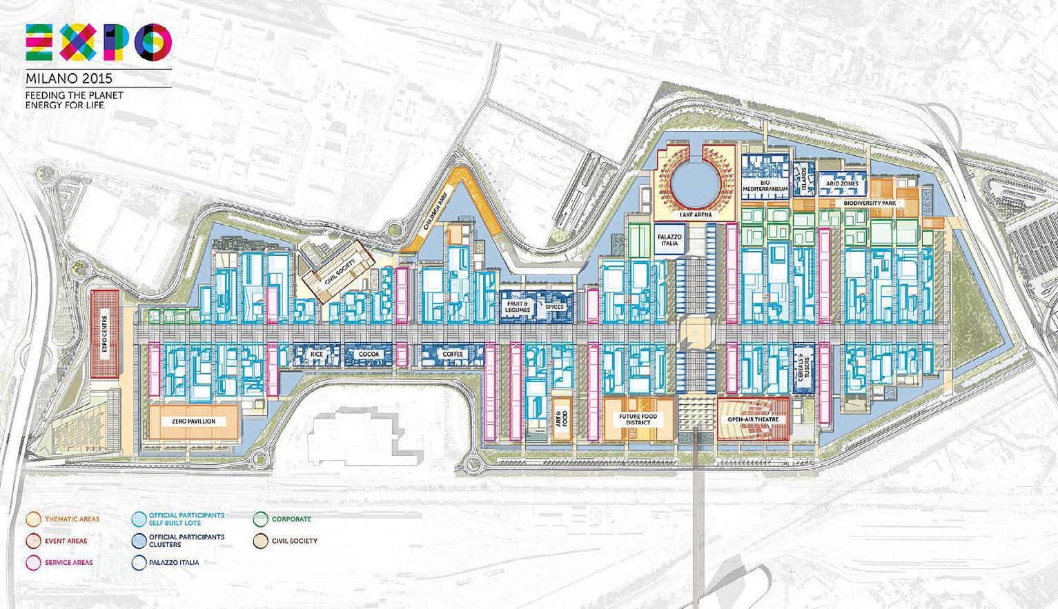
The masterplan, proposed by the architects Jacques Herzog, William McDonough, Stefano Boeri e Richard Burdett, relied on one main principal, the concept of urban spatiality offering the visitors an immediate and direct experience of the theme chosen.
The main element characterizing the project lied on the perpendicular intersection between the Cardo e Decumano, generating a first axis 1.4 km long, placed in line with the old historical track of the Sempione, which hosted the pedestrian and cyclable boulevard. The other axis, which recalls the geometry of the agricultural path that surrounds Milan, was the reference for the National Pavilions that faced the central axis.
At the center of the main intersection rose the Piazza Italia, with an area of over 4000 sqm. At the edge of the north side of the Cardo was built the Tree of Life, surrounded by the Lake Arena, with a diameter of almost 100 m. At the opposite direction instead was located the Open-Air Theaters “San Carlo”, with a capacity of over 9000 people.
7
Figure 8 - EXPO 2015
Figure 9 - View of the Decumano during EXPO 2015
Figure 10 - Israel Pavilion during EXPO 2015
Figure 11 - U.S.A. Pavilion during EXPO 2015
The tree of Life is an installation of 37 m high made by a weave of wood and steel and was designed to be inherited to the future of the new district.
At the end of the west side of the Decumano it is placed the Expo Center, a space with more than 8500 sqm, that hosted a conferences hall and an operation center. At the other side instead, there is the Collina Mediterranea, with an height of 12 meter (82800 cum) that accommodates an olive grove and a typical Mediterranean forest, composed of cork oats (sugheri), holm oak (lecci), cypress and downy oaks (roverelle).
It has been considered a tribute to biodiversity and preservation of the landscape and environmental heritage. It can be visited thanks to a series of ramps that help to reach the top and have a complete look at the EXPO. The trail to the top offered the visitors the opportunity to explore the role of the food biodiversity, tasting food from all over the world and adopt new
consumption habit.
Access to the exhibition was guaranteed by 4 main gates:
- Fiorenza, west gate: connected to Rho Fiera Exposition and the metro line
- Triulza, west gate: next to the previous one, connected with the train station
- Merlata, south gate: connected to Cascina \ Merlata district and to the city of Milan
- Roserio, east gate: firstly, used only by taxi, \ then open also as a pedestrian access
Very important for the connection of the Exposition to the city of Milan was the area next to the south of EXPO, Cascina Merlata, because this was, apart from the west gate, the only tangible connection with the city. This area hosted the EXPO Village and in particular the accommodations facilities for the volunteers, workers, and country delegations.
It was connected to the EXPO thanks to a pedestrian’s bridge, crossing the roads and the railway.
8 Figure 12
- Masterplan EXPO 2015
1.3 - After Expo
After the EXPO 2015, which, according to the data, has been visited by 22.2 million people, a lot of discussions took place about the inherits and the future of the area.

Then dean of the Università Statale of Milan suggests moving inside the future of the area EXPO the scientific department of the university. Matteo Renzi, the then-prime minister, proposed also the Human Technopole project together with the University Statale.
Arexpo issues a call for the elaboration of a masterplan for the urban regeneration of all areas of the Exhibition. They agreed for a concession, by the municipality of Milano, of 99 years for the lease and construction of the new district on the condition to keep an index of construction between 250000 and 480000 sqm of gross floor area. The proposal for the construction of the Galeazzi Hospital exceeded the initially allowerd construction area, but it was still added to the project.
In April 2017 Arexpo evaluated the three major construction agency who passed the qualification criteria: COIMA, STAM and LANDLEASE. The last one, with the Masterplan proposed by the Carlo Ratti Associati, won the competition for the new district.
The Human Technopole Hub instead will be designed by the Piuarch studio, after a competition held in 2019 that involved more than 30 architecture studios.
Mind Anchors
Federated Innovation Institutions Unimi Science Campus Companies Human Technopole

Startups Research
Third Sector IRCCS Galeazzi Fondazione Triulza
Mind Strategies
Environment Well- Being
Social Impact
9
01-History of Context
Figure 13 - EXPO area under demolition
1.4 - MIND- Rearrangement of the city fabric
At the end of the decade the future of the area was defined. A new district, Milano INnovation District, will rise and every day will host more than 60000 people coming to work, study and spend their free time.
MIND will rise from the heredity of the EXPO 2015 and will inherit its main urban structure, the Decumano and Cardo and its connection to the trade fair, exhibition and congress center of Fiera Milano and the city of Milano through the bridge used to connect the EXPO with Cascina Merlata.
The new district, that will be focus on the research in the field of Life Sciences and the city of the future, will host four main anchors: the Galeazzi hospital, Human Technopole, the new campus of the Università Statale and Fondazione Triulza. Alongside those anchors, building with mixed functional spaces will be built, which includes offices, light – industries, residence built-to-rent, retail, services, public spaces, houses for the students and workers.
Since the project is growing and more investors are willing to participate in the future of the MIND, some private companies have decided to join the new district:
- Astrazeneca, pharmaceutical multinational, will be the first to settle in their new offices

- ROLDS, leader of household appliances
- Esselunga, Bio4Dreams, Illumina, Valore Italia and SkyDeck Europe will soon open their branches and offices
- Moreover, several collaboration agreements were signed for building sustainability with Solar Impulse, Built By Nature and E.on
The massing for the workspaces and the ligh industries will follow a compact and flexible grid, while the houses will follow a vertical development. All of those will be connected together by the common ground, a break that join alongside the roofs and the terraces of the buildings, creating a podium on top of the complex
10
Figure 14 - Proposal for the open common ground by Mario Cucinella Architects

-
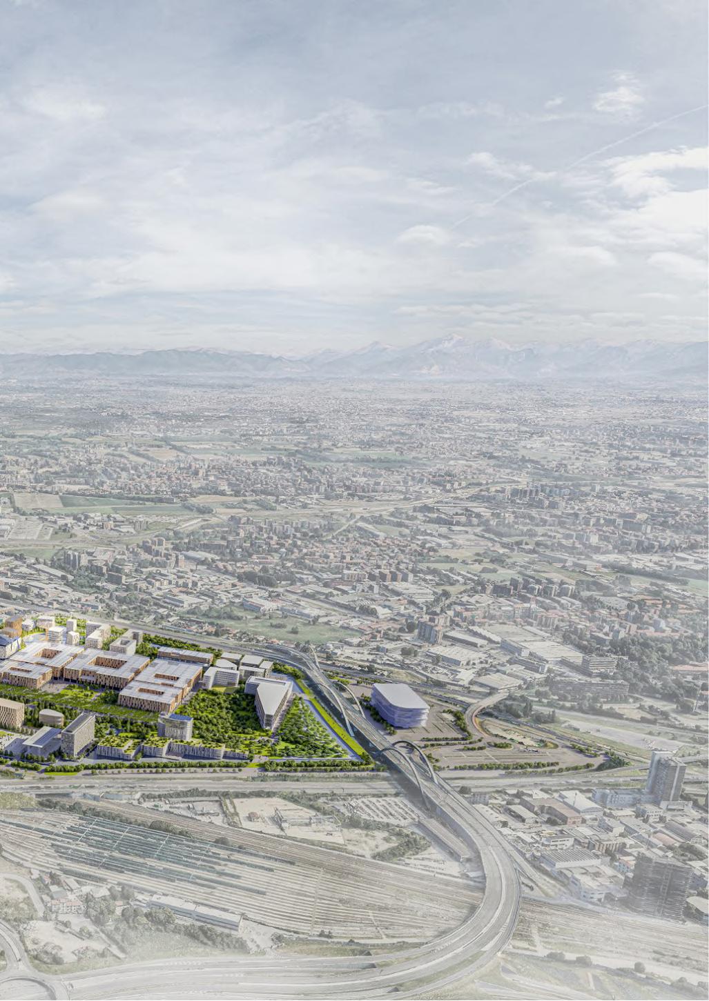 Figure 15 - Approved Masterplan by Carlo Ratti Associati
01-History of Context
The new proposed Masterplan for MIND district and the implementation of the West Gate presented by MCA, Land, Systematica, ARUP, is based on 4 main points:
-Space for work and the innovative creation
-Space for living
-Space for caring
-Space for moving
All these aspects are linked together by the common ground as a unique space of connection at the ground level for pedestrian and slow mobility.
Around Decumano, all the new buildings will take place and its linearity will be broken by the green infrastructure and parks. The main road will be covered with trees and will became the longest linear park in Europe. The district, even more, will be entirely car-free, so the common ground will have the job to keep together all
the aspects with the aim to create a unicum project, giving priority to the pedestrian and the slow mobility.
The master plan predicts buildings imagined for maximum permeability at street level, thanks to a system of public and semi-public courtyards connected to each other and the common areas outside, shops, activities and restaurants are providing dynamism of the area.
Another great innovation at MIND is its high standards of innovation and sustainability, not only at urban level, on which it will be given the LEED certification for Citizen Communities, but also at the building level, where, since the starting of the masterplan, those concepts of modularity and scaling based on DFMA (Design for Manufacturing in Assembly) helps to control the emission of CO2 and carbon during the entire life of the building.

13
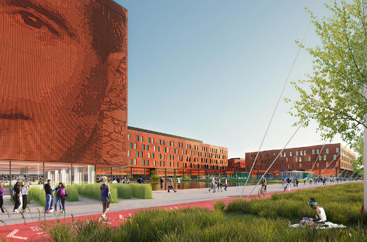
Figure 16 - Proposal for the open common ground by Mario Cucinella Architects

14
Figure 17 - Aerial view of the West Gate by Mario Cucinella Architects
Figure 18- Proposal for the Univerisità di Milano Statale by Carlo Ratti Associati
01-History of Context
1.5 - Proposed Master Plans of Mind
The first proposal Masterplan, submitted by Landlease and designed by Carlo Ratti Associati in 2017, relied mainly on the development and new layout of the Decumano, converted into a one and half kilometre long linear park, one of

the longest in Europe, which becomes the social centre of the neighbourhood.
Alongside this landmark, a mix of plazas, pedestrian areas, shared vegetable gardens, laboratories and retail facilities will take place.
15
In this project, the Decumano became a connection point between the north side of the district, which hosts the leading anchors in MIND, the Galeazzi hospital, Cascina Triulza, Human Technopole and the Università di Milano, and
the south one on which side takes places the offices and research centres, facilities, residences and cultural spaces. At the end they designed the final green park, with some sport facilities integrated in the landscape design.

16
Figure 19 - First Masterplan proposal by Carlo Ratti Associati and PII
01-History of Context
The new proposal presented by Mario Cucinella architects for the implementation and final decision on the West Gate still rely on the Decumano, but its linearity is broken by perpendicular axes, becoming the new

urban trails inside the district.. The rhythm of the new landscape regeneration is interrupted by the green route which completes the new landscape design.
Nature will have a leader role inside this new
17
masterplan, creating a harmonious combination with the urban city fabric, starting from Decumano and irradiating inside the whole district. The common ground will connect the first 10 meters in height of all the buildings, linking together the
district fabric and the landscape urban design. Compared to the previous one, there is a lack of sporting facilities, with a masterplan that reflects the one designed fot the EXPO, with the urban fabric perpendicular and facing the Decumano

18
Figure 20 - New proposed Masterplan with implementation on the West Gate by Mario Cucinella Architects
01-History of Context
The final proposal designed by the studio Carlo Ratti Associati, as the first two masterplans showed, shapes a long linear park on the Decumano, creating different green areas alongside its path. Green is always present between the urban fabric that seems more
integrated inside the the new district, detaching itself from the inheritents of EXPO 2015 At the end of Decumano, on the east side, a more dense greenery and a park is designed between the University and the collina Mediterranea..

19
A new system of gardens and water canals will give birth to a green-blue park all around Mind, an oasis of 120000 sqm, dedicated to biodiversity, connected to the green paths inside the district and with a large body of water
to richness the environmental quality of the area. Moreover, a big green area dedicated to health and food (an inherits from EXPO 2015), starting from Cascina Triulza, will rise to link together the two sides of Decumano.

20
Figure 21 - Approved Masterplan of Mind by Carlo Ratti Associati
- CHAPTER 2 -
INNOVATION DISTRICT ANALYSIS
02.1- MIND in the City Structure 02.2- Entrances and Connections 02.3-Greenery in MIND 02.4- Functional Program of MIND 02.5- MIND Topologies
2.1 - MIND in the City Structure
Like many metropolitan cities in the world, Milano has an innovation district in the city context. It is located west-north of the city center which is a new settlement area. Even though it is located in the perimeter of the city, the area is well connected by the subway and highways. With urban transportation, it is quite convenient to reach Mind area in around 30 minutes from the city center. Despite all these connections, when it comes to the small scale, Mind area is not reachable easily. Although there are some slow mobility connections, it is not enough and some changes are needed.
Three sides of Mind area face the highways and railway. As an advantage of this situation, it can be said that there is a high number of cars passing by daily even at night. It creates a lot of potential in terms of accessibility with a vehicle. On the contrary, for pedestrians, it is a tight corner, because one of the best ways to perceive the context is to experience it by walking. For Mind area, this is one of the main issues that need to be considered.
To address this problem, there are some solutions such as bridges between the surrounding neighborhoods around Mind area. When it is analyzed on a small scale, slow mobility is deemed important and the connections with the surroundings are the essential issues. The figure on the left shows that with different kinds of vehicles it is convenient to reach the area from the city center. Moreover, visitors from other cities can access to Mind without entering the city center by using the ring roads.
Currently, there are some missing slow mobility routes.The figure on the right shows the existing and missing routes for pedestrians and bikers. The routes are passing by the surrounding area of Mind and some of them continues till city center.

As it is seen on the map below Mind might be an intersection point of slow mobility routes in the foreseeable future and these paths could be the base of the potential focal points which create social and commercial life in MIND.

23 02-MIND Analysis
Mobility in the City and around Mind Area
Current and Missing Slow Mobility Routes
Highway Main Road Pedestrian and Cycable Path Trails M1 Metro
Missing Natural Trails Natural Trails Metropolitain Urban Trails Missing Metropolitain Urban Trails
For people who pass from Milan in transit, Mind area can be a stop or a pause. With this position in the city, it has a great future to be the second city center. The current slow mobility routes can be completed within Mind area. Thus it can be part of the city and the importance of the current routes will boost on the urban scale.


When it comes to the Mind scale, the long side distance of the area is 1500 meters and approximately by walking 25-30 minutes. This strong axis called decumano is designed as a car-free path just for pedestrians. However, the roads surrounding the whole area are normal streets with some car parking areas. Between the perimeter road and Mind, there is a canal which seems kind of an obstacle in the current situation. However, in the new master plan, canals are extended to the inside with different shapes to create particular open spaces. In this manner, the landscape layout generates passages and directs pedestrians into the area.
As seen in the figure below, the inside of Mind is completely pedestrian friendly. This walkability on a small urban scale should be extended to reach the area conveniently from all sides. Since Expo, this issue has developed significantly. Nevertheless, the area needs more connection with surrounding neighborhoods. Currently, there is a bridge under construction to the south neighborhoods and a similar connection to the north side can be also considered.

24
Figure 22 - The mobilities in Mınd area
DECUMANO
Mobility around Mind
Current and Missing Slow Mobility Routes Around Mind
- Entrances and Connections
Mind area has relations with roads ‘Autostrada dei Laghi’ to the north, ‘SpexSS11’ to the east, ‘A4 Torino-Trieste’ to the south, and ‘Tangenziale Nord Milano’ to the west. Differences in the level of roads create difficulty in terms of accessibility. In this situation, the location of entrances is important. Nowadays, there are 2 main entrances which are located on the east and west side of the area. The West main entrance is connected with the Rho Fieramilano metro station.
In 2028, a new entrance and metro station will be opened from the south side. This new entrance has a quite strategic point due to the connection with Uptown (the new urban renovation project that was completed recently). With the same approach, the municipality wıth Regıone Lombardia, is planning to do a renovation on the north side of Mind with a project called EXCAVA in 2031. The project is proposed by the team ‘Park Associati’.

Figure 23 - ‘EX CA VA’ by Park Associati Commerce, residence, public spaces and some buildings for the municipality are designed as functions in this project.
In the proposed master plan by them, it is considered to have connections to Mind, since Mind will be one of the big complexes of the area. In the future, as it is observed, the number of entrances is increasing and it will affect the MIND area through its accessibility and social arrangement.
25 02-MIND Analysis
2.2
1
2
Current Situaiton After 2031
1-Entrance from the existing metro station
Within ten years the value of the whole area will increase substantially. The project Excava on the north side and the new redevelopment Uptown project in Cascina Merlata on the south side will have an enormous contribution to the Mind area in terms of urbanism. Within this frame, it is assumed that another entrance (number 4) can be considered with a bridge design, as in the 3. entrance from the new metro station.

In 2028
2-Secondary entrance from parking area

3-Entrance from the new metro station and bridge connection for the Cascina Merlata
4-EXCAVA New Proposed Project for the north side of MIND area

There might be a new bridge above the high way to create an entrance area


26
Figure 24 - ‘EX CA VA’ by Park Associati
1 1
2 3 2 3 4


DECUMANO Galeazzi Hospital Post Office West Gate Galeazzi Hospital Cascina Triulza Uptown Park Merlata Bloom Shopping Center
Fiorenza Maintenance Facility Rho Fieramilano Station (M1) New Metro Station M M 27 Existing Entrance New Entrance Missing natural trail Metropolitain Urban Trail Missing Metropolitain Urban Trail Natural trail
Milano
Universita Statale di Milano Human Technopole Collina Mediterranea New Project EXCAVA Collina Mediterranea Train towards to Garibaldi Station Human Technopole Universita Statale di Milano Open Air Theather 28 Manufacture Commercial Station Prison AccomodationHotel Education Housing Housing-Commercial
2.3 - Greenery in MIND
Green environments are one of the most essential landscape elements in Mind. According to the function of the building, the usage of the green spaces varies. For instance, the green area usage in the courtyard of university buildings is significantly more than other green spaces.
The map below shows the differences in the greenery according to their relations with the function of the building. On the axis of decumano, public greeneries are formed by its accessibility. Green areas between more private buildings such as offices or semi-public spaces have limited users.
As you go to the east side of Mind area it is clearly seen that the density of greenery is increasing visibly. It creates more social life on that side by itself.
Around the university building, there is a park next to the Decumano and it continues till the end of the east border. We can consider that these areas have more green density compared to the other side of Mind. On the eastern side at the end of Decumano there is an artificial hill called Collina Mediterranea with a 12-meter height and it creates a buffer zone between Mind and the highway bridge. With the walking path on the hill, it is possible to see all Mind from top and it is important to have a powerful connection between Decumano and the hill due to its strategic location. In the district, the idea of having greenery is not only to have some parks between the buildings but it is also aimed to create spaces with greenery on the different levels of the some structures.
29 02-MIND Analysis
Mixed Use Education Commercial
Less Public Health Student Residence Laboratory
As it is seen in the figure25 green areas shape the open spaces for several functions such as leisure time or sports activities. This concept continues also on the ground floor of the buildings. The open ground floor design provides permeability between open and closed spaces. It makes it possible to create more public spaces smoothly (figure26). Greenery can be also considered on the upper levels. Some proposals in Mind bring the green area to the upper floors to create public and semi-public spaces on different levels. The axonometric drawings in figure27 belong to Human Technopole in the Mind area. The headquarters of scientific laboratories for the campus. It will complete the renowned Italian research institute’s cluster, adjacent to the State University’s campus. It is seen that the common ground idea continues till the roof level and it gives a completely different atmosphere to the visitors. Hence, it is possible to bring public areas from the ground level to the upper levels by implementing green public roof designs.


30
Human Technople
2.4- Functional Program of MIND
At MIND area, the vision includes a variety of functions by proposing business and scientific centers. Masterplan the functions are conceived as districts: the West Gate, the Green Heart, and the Knowledge Hub.
The new district forms an ecosystem based on education, work, sport, accommodation, commercial, entertainment, and services. Public and private functions coexist in MIND area and users are researchers, students, professionals, and residents. Different user profiles create great potential related to companies and start-ups. The headquarters of public interest act within the district as real urban catalysts: These buildings are; Human Technopole,
IRCCS Galeazzi, Triulza Foundation, and Science Campus of the University of Milan.
At the west gate, mixed used-commercial functions are located in the majority. On the east, the University of Milan plays an essential role. Green areas are spread over the site, and public green areas are focusing mostly on the surroundings of Decumano. This green corridor supports the social contribution of the MIND’s vision. On the south next to the new metro station, an open-air theatre is located which creates another attraction point. At the surrounding site, Fiera Milano(on the west) and uptown mall (on the south) build social activity spaces that feed the MIND area as well.
31
02-MIND Analysis
Mixed Use Education Commercial
Less Public Health Housing Hotel Laboratory

32
Figure 28 - Mind and New Surrounding Projects
2 5
3 1 4
The typology of the structures are depending on the functions mainly and in Mind we can see this situation clearly. Similarly, in some regions, there are volumes with more than 5-6 stories with a large footprint mostly for education functions. On the contrary, functions for accommodation or commercial structures have smaller volumes.

To make a comparison of volumes with the city of Milan, 5 regions are chosen from the master plan. In the region 1 and 2 commercial buildings are located primarily and they have similar volumes.

Region 3 has particular volume shapes and sizes with the education function. When it is compared to Politecnico Leonardo Campus, the differences between volumetric density are visible in all respects.
Region 2
Region 4
In regions 4 and 5 there are some mixed-use structures and in the comparison between the historical city center of Milano, building clusters in the center have more density than Mind area. However, in the last image the overlapping with Isola area (which is the new settlement area of the city) it can be seen the similarities in terms of the building volume.


Typıcal Housing Cluster in the City Center
To conclude this part we can say that buildings with education functions differentiate from other parts of the master plan. The same situation can be seen also in the city with a similar courtyard typology and wide footprint. In addition, Mind typologies resemble some parts of the city except the historical city center which has high building density. The new proposed structure in the master plan is designed within this framework.

Location of Proposed Design
Volume Schemes
Building Program
Design Strategies -CHAPTER 303.1-
03.2-
03.3-
3.1 - Location of Proposed Design
Context awareness is essential and in this area, surrounding elements’ axis with orientation are taken into consideration. Mixed-used buildings at the north and south can be beneficial for the project. To the west, there is the State University cluster and to the east the Mediterranean Hill.
The hill is a powerful component but in the current situation, it is not given importance. With the proposal, regaining the site’s potential is one of the critical issues. Another important factor of the master plan is the water in the site. It surrounds the site and affects the accessibility of MIND.
The map below shows future focal areas in MIND. According to the map, the east side has potential due to amount of public green
spaces near Decumano, a type of entrances. and University. In the north, the EX CA VA project is providing the new entrance in the future. Adjacencies of the site have great capacities and the project, is aimed to profit from these elements.
As a result of the analysis, the area shown in the section below is selected for the project site. This area is located on the east side of the district. The suggested site for the project is enclosed by all different profitable elements and this creates the promising potential for the site. It has a direct relation with the university and Collina Mediterranea hill. Furthermore, the north, east, and south main entrance axis are also crucial and have effects on the chosen site.
UNIVERSITY 37 03-Design Stratagies
38
Stratagies
The site’s location has a great potential of a public park. The volume of the building is constructed according to the reference of surroundings. To the west, there is a university that creates a social component near the site. On the East side, there is the hill which brings an important connection with the volume.
In the North, two main entrances are located. In the South, the documano connects with the chosen site area. These elements formed the general layout of the building. The general idea occurred by the continuation of public spaces by connecting existing landscapes. Volume is shaped by the general idea of ‘landscape integration’.

1-Footprint-Axis
The footprint is shaped according to the axis. At surrounding, there are two main entrances; at the east and at the north. North entrance will take more importance with the proposal ‘EX CA VA’, university, and the decumano.
UNIVERSITY
HILL
2-Massing
Mass is elevated according to the footprint. Mass is folded from the landscape to create a continuity of the green idea, and under the mass closed areas are designed. The South touches the ground which creates a connection with the terrain. This elevated terrain identifies a walkable roof.
39 03-Design
MIXED USE MIXED USE 3.2
- Volume
Schemes
3- University Axis- Functions
The program of the building is the ‘ Recreation and Sports Center’ and the main functions are separated by the ‘urban link’. This link is connected with the university and the hill and it is a permeable and flexible space.
4-Folded Mass
Sports center functions are elevated by the folded-shaped floors. Functions at the elevated mass connect with the roof. The general form is creating a folded terrain idea which comes out from the ground.
5-Skylight
Skylights are formed with the same idea of folding the landscape and they are placed according to the need for sunlight in spaces. These skylights build a visual connection between the walkable roof and indoor spaces.
6-Landscape Integration
The continuity of the landscape is the main idea of the project. Mass is oriented and formed according to context. The landscape of MIND continues and moves through the walkable roof of the project. In the end, it creates terrain folded mass which is integrated with the landscape.
CENTERSPORT RECREATION
40
Figure 29 - Mind and The Main Important Functions Inside
Functions in the site provide the vision of creating an attraction. The project is situated east of MIND which is between the university and the hill. Different kinds of users are involved in the area. University is located at the heart of the MIND. Students are the important users at the east of the site.

It is observed that ‘Recreation and a Sports center’ can be required on the site. Mostly, commercial and laboratory function buildings are involved in MIND. Entertainment is foreseen to be a good fitting by its function and by its location. The project is situated in an important area because of its closeness to the university and entrances of the MIND. With the proposal project, the east side of Mind will have an activity center.
Before, the project site had an undeveloped green area. The project proposes defined outdoor activities while protecting public green areas.
There are three main functions in the building: -Sport Center -Recreation Center -Care Theraphy Center
These main functions are supported with many outdoor activity areas, likewise, there are some indoor functions which connects these main functions and and creates thresolds between them.
Outdoor Spaces
- Football Field - Basketball court - Paddle court - Tennis court - Volleyball court - Skateboard Area (with tribuns on the Collina Mediterranea)
-Activity areas on the green piazza (public roof): -Table Tennis -Yoga Pilates Mats -Sitting Areas etc.
41 03-Design Stratagies 3.3 - Building Program
Sport Center
- Athletic Gym
Basketball court Locker Rooms Grandstands Climbing wall area with common locker rooms
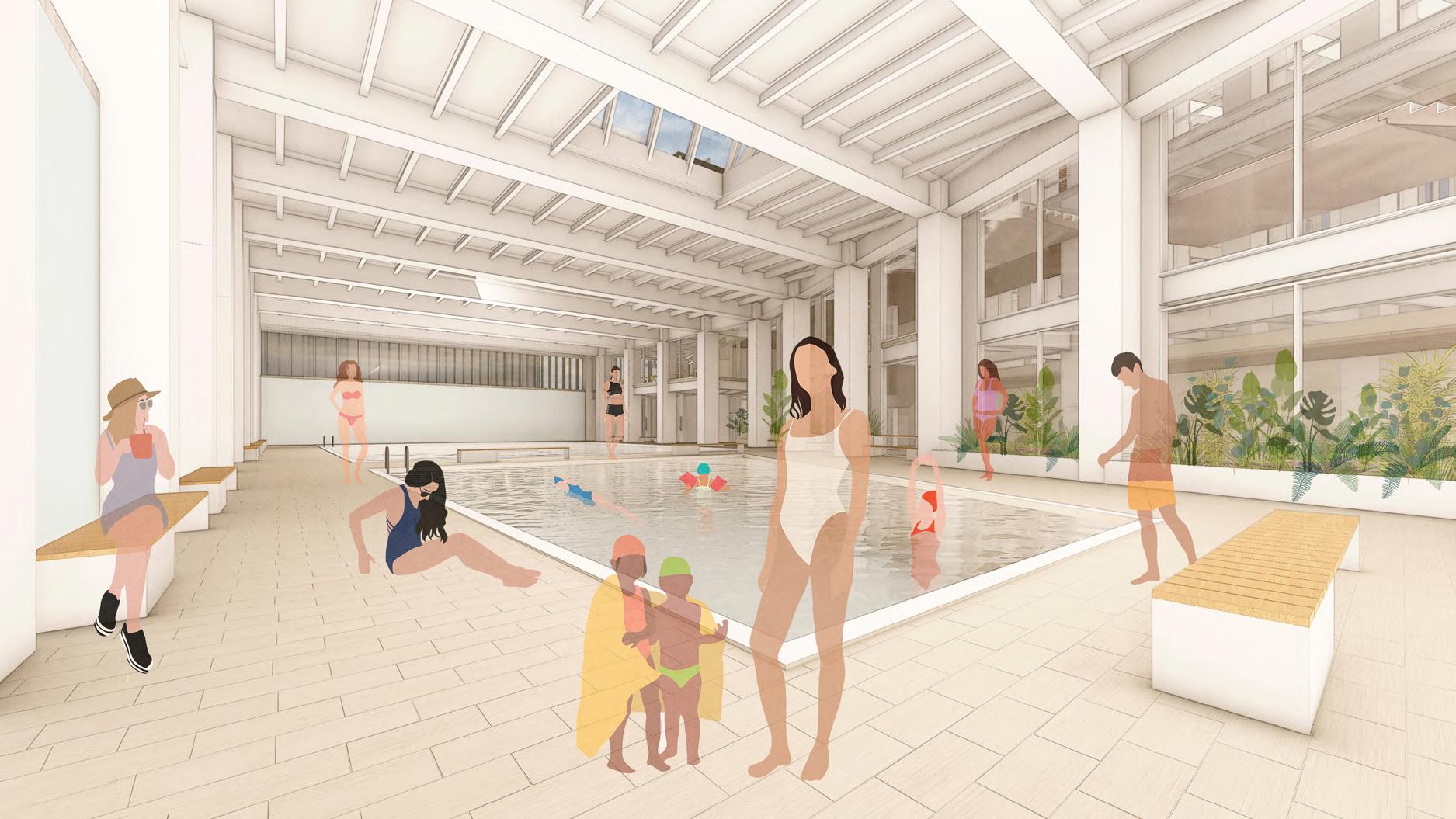
- Aquatic Gym 2 Pools (semi-olimpic and training pools) Locker Rooms


- Fitness Weight Gym
Weight-lifting area Cardio-fitness area Training courses area Minor gym area Locker Rooms - Multi functional room - Cinema - Theather - Ball Room - Workshop
Fitness Gym Green Piazza
Public Passage - Reception - Offices - Cafe - Retail, Shop
-Tecnical Spaces
Recreation Center Care Theraphy Center
- Reception - First aid room - Patient Rooms - Laboratories


Aquatic Gym
Care Center Public Passage
Fitness Gym Recreation Center
Athletic Gym
42
Eco-Roof
- CHAPTER 4 -
Case Study
04.1- Hangzhou Cloud Town Exhibition-Convention Centre 04.2- Changchun Community Sports Complex
04-Case Study
‘Landscape urbanism’ represents a new experimentation that combines urban planning and landscape design. According to James Corner, landscape acts as a powerful bridge between nature and culture. He says ‘It can renew the common and banal and reconcile our modern estrangement from the place.’
In landscape urbanism, culture and nature complement each other through the combination of a new type of public space where the landscape drives the process of urban transformation. Transform the territory, and finding new hybrid spaces in the city are part of the investigation of landscape design.

Landscape design is more than filling gaps between buildings, and blocks. It is finding coherence between nature and culture by attempting to find the character of the space. In the proposed project in MIND, it is investigated how to create urban transformation by reviving the character of the site in the urban void.
There is a hierarchy between ‘public’ and ‘private’ spaces. At the present time, increasing awareness of the response of spaces to new social and cultural demands. In the research and case studies, there is an exploration of these connections between landscape and city content.
45
4.1 - Hangzhou
Figure 30- The Green Continuation from the hill (next to the project site) to roof
Cloud Town Exhibition-Convention Centre
The project is located in Hangzhou. ‘Approach Design’ studio looked from a different perspective for an ‘exhibition center’. “Just when everyone expected an even larger, iconic building, we designed it as a park,” says the ‘Approach Design’. In general, examples of exhibition centers are iconic large buildings. The studio proposed a new intention for an exhibition center. With this intention, it is foreseen to not intimidate people. The studio proposed a public park on the rooftop of the Convention Center. It is about questioning the coexistence of public parks and convention centers. The studio offers a new way to achieve more of the utilization of the
center by integrating with urban public facilities. Reducing the building’s size was one of the first steps to be less ‘aggressive’. 66,000 square meters are compressed to 6.6 meters tall. It is aimed to attract people to the urban public park and provide this building to be able to be used in daily life too.
This roof is called ‘3D Park’ and the rooftop park is accessible from several places. Therefore it is possible to enter the roof from one side of the building and by using other staircases visitors can reach the other street level again. In this way, the permeability of the roof can work together with the existing landscape.

46
Figure 31- The Public Roof Topview
04-Case Study
The rooftop is not just a typical park. It offers different kinds of outdoor activities such as football, a watchtower, a sand pit, a studio theatre, a roller skating platform, a community vegetable garden, a pavilion, and hopscotch. These kind of activities are not very common facilities in Convention and Exhibition Centers.

The interior of the building is not only an exhibition center but also a mixed-use sports facility. When there are no conferences, the exhibition hall can be transformed easily into sport facility spaces such as basketball, table tennis, fitness, etc. It is designed to use the wide capacity of the building.

47
Figure 33- The Public and its accessibility
Figure 32- Some Indoor Areas for the Public Usage Except from Convention Center
The integration of indoor and outdoor areas is one of the major inspirations for the proposed project in MIND by using the idea of landscape transformation. In many big cities, the relationship with nature is getting weaker. With this idea, it is provided to embrace nature while designing a new building. It is about questioning a new approach to understanding how public parks and Convention Centers/Recreation and Sport centers can share common spaces and facilities together.
In this Convention Center, a public park attracts and catches people. It creates a

In this case study and project in MIND, buildings give space to the public with the green rooftop park. From the top perspective view at the Convention Center, the act of unity of the green areas in the surrounding is observed. This is one of the other inspirations for the proposed project of MIND.
Nowadays, the idea of creating livable spaces is changing according to needs. In this case study, the link between the park and the Convention Center is an interesting interrogation. In the project in MIND, the connection between interior and exterior

48
Figure 34 - The steps on roof and its integration with te indoor areas
04-Case Study 4.2 - Changchun Community Sports Complex

‘GBBN’ architecture office designed Changchun Community Sport Complex and which is located in a changing neighborhood. The building is separated into 2 spaces; one for the basketball court and climbing wall and the other one is for a coffee shop, community space, and gym. The building itself is connected by a path through a sculpted landscape. The landscape makes bending movements and orients through the building. According to the typology of the building, spaces are separated to have a clear distribution of 2 different spaces; sports and recreation. There is a connection between these spaces which means that it is not divided independently.
Permeability between spaces is the important point of this project. It is seen that there are no strict borders between spaces which gives flexibility.
The material and form are taken from references from the history of the site. Three elements are taken from the powerplant: the sawtooth roof, the smokestack, and power. In the project taking into consideration, the character of the land gives value to the project.
Similarities between this project and the proposal project in MIND are the approach of the separation of main functions in the building and the connection between them and the investigation of landscape interpretation by bonding with the building.
49
Figure 35 - Context of the project
Figure 37 - Axonometric
Figure 38 - Ground Floor Plan


50
Figure 36 - View from entrance
-
CHAPTER 5 -
BUILDING DESIGN
05.1- Master Plan 05.2- Green Roof and Skylights 05.3- Manifesto Section 05.4- Floor Plans 05.5- Sections 05.6- Facade Concept & Elevation

The master plan is designed as a continuation of the park next to Decumano. In the general layout of the proposed master plan, new bridges to Excava and Collina Mediterranea are considered. When it is reached at the end of Decumano the proposed structure is creating a new focal point in the area. With the idea of a folding landscape, the design respects the green and creates livable spaces within this concept.


The pavement on the roof is continuing till buildings on the south. Similar benches and pavement like on the roof also can be seen in the surrounding area. Thus, the green roof becomes a part of the landscape more effectively. Landscape integration is not designed only with green roofs but also pavements, plants, and continuation of water from canals are supporting elements to develop the master plan. Pavement starts from buildings on the south part and continues all over the roof. Besides, water is located parallel to the building to have the alignment and to create a loop with the canals on the perimeter of the Mind area.
The urban section longitudinally crossing Decumano from west to east shows how the building mediates the relations between the Hill, 12-meter-high, and the University Campus, 25-meter-high. The proposed design redresses the balance in the surrounding context by creating the landscape.

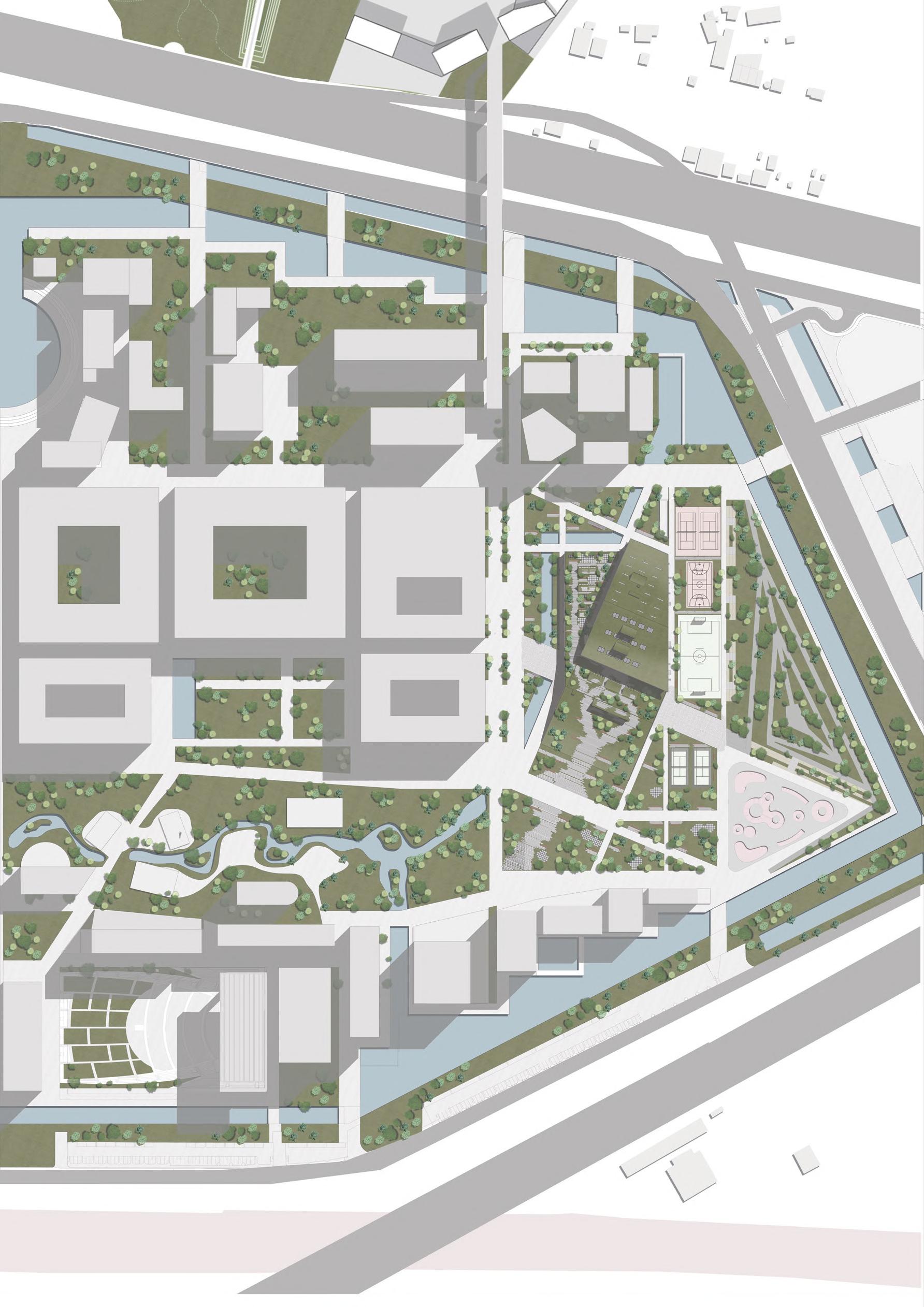
55 05-Building Design 5.1 - Master
Hill
Facilities
Plan 1- New Bridge to Excava 2- Green Roof 3-
& Open Sport
MIND RECREATION AND SPORT CENTER

56 DECUMANO
UNIVERSITY
COLLINA MEDITERRANEA
5.2 - Green Roofs and Skylights

The width of the building on the south side is approximately 60 m. As we go to the north side of the structure it becomes larger. After the sunlight analysis to bring the sunlight to indoor areas better, it is decided to use skylights to have also visual connection between the public roof and closed spaces.
One of the other important considerations is their functions and location of them. Eventually, the locations of skylights are arranged according to functions and the darkest point under the roof. The forming process is done with the same idea of folding landscape as is seen in the section diagrams below.
57 05-Building Design
Green Piazza
Eco-Roof
Lower roof is the major public space in the design proposal. It creates the continuation of Decumano within the park next to it. The path on the decumano continues till the end of the Green Piazza and this path defines the activities on the roof such as sport and leisure time activities.

Upper roof contains solar panels and wind turbines. It is accessible from the main core in the building only for the maintenance. There are three big skylights located on this roof. They provide the sunlight inside of the building to reduce the consumption of electricity and to avoid the use of artificial light.
 Green Piazza Scenarios :Roof Events
Green Piazza Scenarios :Leisure Activities
Green Piazza Scenarios :Roof Events
Green Piazza Scenarios :Leisure Activities
5.3 - Manifesto Section
The longitudinal section presents the idea of the project in brief: It constitutes the Manifesto of the Sport and Recreation Center’s vision and construction conception, it expresses how the structural system and building services, as the technological and material choices, combine to give shape to the architecture. The approach is aimed at continuing the public space by the integration of the existing terrain. Landscape regeneration is prevailing over the structure. In this way, the building is recognised as being part of the terrain.


60
60


63 63

64
- Floor Plans
Ground Floor Plan in the Context

Beside the green roof, the public passage is one of the most important public areas in the building. It has a strategic location in terms of having a connection between the hill and the university. Even though the public passage divides the building into two parts, a public, permeable and vital “threshold” identifying the main functional nuclei: on the one side, the sports center, and on the other side the recreation facilities. Moreover, this passage also originates from a shortcut from university buildings to Collina Mediterranea. With the help of folding doors on both sides, it is possible to convert this area into a semi-open space. As the same pavement characterizes both the urban axis and the indoor environment of the “passage”, visitors will have the perception of walking on the street even passing under the green roof. Thus, the passage becomes a real public space or passageway by itself.
Distribution of functions in the structure:
On the south side of the passage, the recreation center is located and on the ground floor the offices, cinema, and theater are positioned. On the other side of the passage sport and care center are located. From the passage, we reach the main circulation area of this side. On the ground floor, athletic gym and care center are located. Even though the main entrance for the care center is from outside, it has a connection with the main circulation of the building. The main circulation area includes also monolithic staircases to go down (for the aquatic gym) or to go up (for the fitness gym).
65
Design
05-Building
5.4
66
Main Entrance and Passage in the context
Standing adjacent to the University of Milan’s compound, the Recreation Center features a “permable” ground floor and accesses designed concerning the main pedestrian paths structuring the campus.
For this reason, the campus’s central axis continues, bending, towards Collina Mediterranea, while crossing the main foyer of the new building complex and revealing the sports facilities through the public passage.
-3d sectioned view from Decumano
-On the right rendered view from at the end of the Decumano.
-3d sectioned view from the university complex to show the continuation of the road into the proposed design.

-On the right rendered view from the public passage
This “passage” can be considered a semiopen area, thanks to the folding doors on both sides, conceived as a proper urban street. Moreover, the change in orientation generated by the pedestrian path shapes the main volumes of the Rec Center, starting from the southern part in front of Decumano. A strip of the park ascends directing the visitors to the district’s northeastern entrances and welcoming pedestrian flows from Decumano on top of the building’s green roof.
67 05-Building Design
Even though the maximum height of the structure is 17m, as can be clearly understood from the views the Recreation and Sport Center is an integral part of the landscape.

The vision of the building, with its ascending green roof, merges with that of Collina Mediterranea, which becomes part of the new park.

68
Passsage View
View from Decumano

Basement Floor Plan
RoomTechnical BallRoom Cinema Workshop Theather Storage
Storage Storage
AreaLoading 69 05-Building Design
Aquatic Gym LockerAquaticGym Rooms StreamBath RoomTechnical RoomTechnical
Sauna
RoomTechnical

Ground Floor Plan
RoomsAtleticGymLocker WallClimbing Office PublicPassage Cinema Theather Cafe Multifunctional Room Store Reception Cafe 70
CareCenter GymAtletic
Athletic Gym Scenarios
The athletic gym, as it was designed, can change its interior layout and arrangement depending on the activities that will host.
For instance, volleyball, basketball matches or recreational activities such as chess tournaments and board games competition.


05-Building Design


72
Views
Athletic Gym

First Floor Plan 73 05-Building Design
FitnessGym Cafe MinorGym WeightArea
AreaCourseTrainingFitnessGym

CardioArea
Second Floor Plan 74

75 05-Building Design
Aquatic Gym View
Ball Room View


5.5 - Sections 76 West Facade
BB Section CC Section


5.6 - Facade Concept &
77
Elevations
Facade designs are made according to conceptual ideas and lighting. To provide more light for the indoor spaces, transparent façade is chosen for all the envelopes. To take the sunlight in a controlled way wood shading system is used to have a better connection with green roofs and to have a nature-friendly material. These shaders identify the shell of the building with its waved form with rectangle-sectioned timber elements.
To differentiate the two main volumes, shaders are used differently. Even though the horizontal section of the shader is the same in all facades, the vertical section is faulted in some places which give the waved effect to the envelope. Under
the lower roof straight sectioned timber, and under the upper roof angled sections are used. Along with shader shapes, distances between each timber is changing according to the function inside. The plan on the right shows the distance between shading elements depending on the function. Three distances are applied; 40-60-80 cm. For instance, on the side envelope of the care center that requires more privacy the distance is 40 cm (red dashed line). In public spaces such as recreation center, this distance increases to 80cm. This rule that is applied to the facade gives a rhythm to the facade and it creates regulation related to need.

Passage
78
View
Tubular Beam 40*40cm


L Shape Steel Profile 8*28cm

T Shape Steel Profile 40*40cm
Wood Shading System 30*10cm

79
05-Building Design FH B3 SH TS Sr TS
Manifesto Section Detail
North Facade Detail Section
Detail of Wood Shading System on the Facade
Design
80
Roof Entrance Detail Section on the dilatation area
- CHAPTER 6 -
Structure Design
06.1 - Structural concept and decision 06.2- Aquatic gym structural design
06.3- Structural drawings
6.1 Structural concept and decision
The main body of the building has a steel structure formed by the columns that follow the structural grid, the staircases and elevators as a core which are also useful for the stability of the building. As horizontal elements, we designed secondary beams which support the corrugated sheet-concrete slab and primary beams to support the load of the slab and the secondary beam. Our building consist of two main bodies, one starting from the ground and lifting to the first floor, and the other reaching to the third floor.
The entrance at the ground floor can be seen as a point of connection between two functions in the same building;
On the right side we can find the recreation centre, which, following the inclination of the roof, hosts the entrance to the cinema, theatre and ballroom, all of these take place on the lower level, and some offices at both levels; at the
left side of the entrance we placed the sports activities centre, which at the ground floor host the athletic gym, its changing rooms and also the entrance to the aquatic gym at the lower level.
Still on the ground floor is located the care centre, with its entrance from the north side of the complex and a direct connection with the sports centre.
The first floor hosts the fitness gym, the weight gym, the minor gym and its changing rooms, while on the second floor is placed the cardio area and the training course area.
At the basement level, we can find the entrance to the ballroom, the cinema, the theatre and a workshop area. On the opposite side of the basement level, under the gym, we located the aquatic gym and its changing rooms. Technical rooms are also located there.
06Structure Desing
83
Walkable green Roof Not
- walkable green roof

84
Structural and architectural plan overlapping
06Structure Desing 85
86
The building is designed with different grids according to the function inside. The most regular one, which can be found on the north side of the building at the gym, follows a grid of 6 x 9 m as a basic module.
In the south part instead, where we placed the recreation centre since we needed bigger space inside, we designed a grid of 9 x 12 m, and in some parts also 9 x 15 m.
The largest span we have in our building is placed and designed for the aquatic gym and the athletic gym; in the first one, we designed a grid of 5 x 26 m, while the second one is 3 x 30 m.
Before proceeding with the design of all structural elements it is necessary to calculate the loads.
Each building is subject to different types of loads, which are divided into dead loads and live loads: dead loads are loads of the self-weight of all permanent construction such as beams, columns, floors, walls, roofs and finishes, which are due to the effects of gravity. The computation of the self-weight of the building elements takes into account their size and specific density.
As for living loads, they are loads that are due to variable effects such as the movement of people, furniture, equipment and traffic. The weight considered in this case varies depending on the type of use envisaged for the building and the category of the same.
This information will then be used as the first data to calculate the forces acting on the building. We have considered the biggest value that we have in the project, according to the use of the different floors. Therefore, looking at the floor most stressed, we have considered 5 kN/m2 as the standard for the gyms and the activities inside our building.
The sum of all these factors is the result of the forces acting because of the weight of the elements considered. To proceed with the verification and design of the structural elements, the value considered is to be scaled through some safety factors, which allows us to verify the structure with a greater safety margin.
The load case combination used for element design during verification of the ultimate limit state (USL) conditions is: 1.35G1 + 1.5G2+ 1.5Q1.
06Structure Desing
ground level 0.00 Level bulkhead -8.45 Level excavation level -6.45 basement level -5.00 A B C D E F G H I J K L M N O P R S T U V Y Z AA BA CA DA EA first level 5.00 second level 10.00 roof level 17.00 first roof top 8.00 3.00 3.00 3.00 3.00 3.00 3.00 3.00 3.00 3.00 3.00 3.00 3.00 6.00 6.00 6.00 6.00 6.00 6.00 6.00 9.00 9.00 9.00 9.00 9.00 6.00 9.00 60.00 78.00 0.61 1 : 200 Section AA ST 1 Section A - A’ 87
88
Structural plan - ground floor
06Structure Desing
Slab design - Load analysis
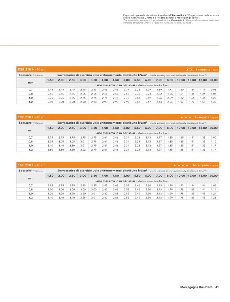
Since we are designing a steel structure, we decided to use slabs with collaborating concrete sheet metal. To define the one perfect for our project we need to calculate the sum of


30.04.2021
W = 1.35 x G1 + 1.5 x Q1= 14.52 kN/m
100
10 10 14 8 15
30.04.2021
5,5
1/2
89
Continous beam design: Secondary beam
Looking more in detail at the computation of the total bearing loads of the secondary beams, we will consider the influenced area of 1.5 meters, according to the structural grids. In that case, we have to consider the self-weight (G2), the slab weight including the corrugated sheet (G1), and the considered live loads and we will magnify those values by the safety factor.
Dead loads G1:
- Soil: 15 cm 3.0 kN/m2
- Drainage board: 06 cm 0.1 kN/m2
- Insulation: 14 cm 0.05 kN/m2
- Screed: 10 cm 2.0 kN/m2
- Corrugated sheet: 10 cm 1.9 kN/m2
Total: 7.1 kN/m2
Dead loads G2:
- IPE 330 weight: 0.49 kN/m2
Live loads Q1:
- Offices / gyms: 5 kN/m2 Total: 5 kN/m2
Loads combination: W = 1.35 x (G1+G2) + 1.5 x Q1= 16.95 kN/m2
IPE 330 (S235) properties:
- Lenght (L): 6 m
- Infleance area: 1.5 m
- Weight (G2): 0.49 kN/m2
- Wpl adm: 804.3*103 mm3
- I y : 11770 * 104 mm4
- E: 206000 MPa
- fyd (235/1.05): 224 MPa
Calculation and verification: First we calculate the Maximum Bending moment: M (W*L2/8): 123.37 kNm Then we calculate the Section modulus: Wpl max (M/fyd):: 551*103 mm3
Section modulus verification: Wpladm > Wplmax 804.3*103 > 551*103 mm3
The second important check that needs to be done is the maximum displacement; for this one, we took in consideration both the Dead loads and the Live loads. First, we calculate the admissible displacement that the IPE 330 can withstand and the maximum we calculated: Sadm (L/200): 30 mm S max (5*ql4/384*EI): 13 mm
Maximum displacement verification: Sadm > S max 30 > 13 mm
The last one is the Ultimate Limit State (ULS): We calculate the admissible shear forces and maximum one calculated: Vadm: 426.8 kN V max : 82.2 kN
Ultimate Limit State verification: Vadm > V max : 426.8 > 82.2 kN
IPE 330: VERIFIED
90
06Structure Desing
Continous beam design: Primary beam
Looking more in detail at the computation of the total bearing loads of the primary beams, we will consider the influenced area of 6 meters, according to the structural grids. In that case, we have to consider the self weight (G2), the slab weight (G1), the considered live loads and we will magnify those values by the safety factor.
Dead loads G1:
- Soil: 15 cm 3.0 kN/m2
- Drainage board: 06 cm 0.1 kN/m2
- Insulation: 14 cm 0.05 kN/m2
- Screed: 10 cm 2.0 kN/m2
- Corrugated sheet: 10 cm 1.9 kN/m2
Total: 7.1 kN/m2
Dead loads G2:
- HEM 700 weight: 3 kN/m2
Live loads Q1:
- Offices / gyms: 5 kN/m2 Total: 5 kN/m2
Loads combination: W = 1.35 x (G1+G2) + 1.5 x Q1: 21 kN/m2
HEM 700 (S235) properties:
- Lenght (L): 9 m
- Infleance area: 6 m
- Weight (G2): 3 kN/m2
- Wpl adm: 9198*103 mm3
- I y : 329300 * 104 mm4
- E: 206000 MPa
- fyd (235/1.05): 224 MPa
continuousbeam3spans: l:9.009.009.00m
permanentloads: p:111.00111.00111.00kN/m
liveloads: P:164.40164.40164.40kN a=1.501.501.50m P:164.40164.40164.40kN a=3.003.003.00m P:164.40164.40164.40kN a=4.504.504.50m P:164.40164.40164.40kN a=6.006.006.00m P:164.40164.40164.40kN a=7.507.507.50m
Calculation and verification: First we calculate the Maximum Bending moment: M (W*L2/8): 1906.05 kNm
M -1906.05 kNm 1587.58 kNm
-1.9k
Then we calculate the Section modulus: Wpl max (M/fyd): 8516*103 mm3
Section modulus verification: Wpladm > Wplmax 1906.5*103 > 8516*103 mm3
The second important check that needs to be done is the maximum displacement; first we calculate the admissible displacemnt and then the mazimum we calculted: Sadm (L/200): 45 mm S max (5*ql4/384*EI): 9.5 mm
Maximum displacement verification: Sadm > S max : 45 > 9.5 mm
The last one is the Ultimate Limit State (ULS): We calculate the admissible shear forces and maximum one calculated: Vadm: 2501.1 kN V max : 1122.3 kN
Ultimate Limit State verification: Vadm > V max : 2501.1 > 1122.3 kN
HEM 700: VERIFIED
results-characteristicloads(1.01.0): Mmax:1587.58902.921587.58kNm Mmin:-1906.05-1906.05-1906.05kNm Vmax:762.65990.421122.28kN Vmin:-1122.28-990.42-762.65kN EIdmax:11978.895164.8911978.89m EIdmin:-157.56-3990.14-157.56m Rmax:762.652112.702112.70762.65kN Rmin:351.651098.901098.90351.65kN M: 1.6k 91
Column design:
The columns of the building we designed, follow the structural grid. For this reason, they have a distance, between each other, of 9 m in the horizontal direction and 6 m.
The design choices of the columns, regarding the materials, are similar to those of the floor. The calculation of the pillar takes in consideration the weight of just the primary beams in two directions (R1) and the loads of the primary beams, the secondary beams supported by the previous one and the slab loads (R2):
R1 (G2*L2/2): 18 kN R2 (G2*L2/2 + n*V): 424.75 kN (n*V: number * shear forces secondary beams)
Column weight: 3 kN Number of floors: 4 Total: 3486.15 kN
5 m
Column
R1 R1
The sum of all these loads, plus the weight of the column itself and number of floors will give us the maximum loads that the column needs to bear. The Preliminar calculation leads us to use the same profile as the primary beam: HEM 700. The final check on the steel column regards the maximum compression check the steel profile can resist. According to the maximum value we calculate we can see if the difference doesn’t exceed the standard value of 75%.
871.53 kN 5 m 5 m
1743.08 kN
R2 R2 2614.61 kN
5 m 3486.15 kN 92
The check regarding the column needs to be done according to the compression check, where the difference must not exceed the 75%, - λ1 (S235): λ = 0.76 - λ = 0.76: X = 0.7247 Nrdadm: 5672 kN Nedmax:: 3486.15 kN Nrdadm / Nedmax: 61 % < 75%
HEM 700: VERIFIED
6.2 Aquatic gym structural design
As already mentioned, the aquatic gym occupies the basement level and the ground floor, but it is only accessible by the lower floor, with a staircase directly connected with the main circulation area.
The main room has an irregular shape determined by the grids, functions and layout of the building. The widest part of the room has a dimension of 26 x 25 m, with a total area of more than 1300 m2, and it’s spanned alongside the 26 m wide side every 5.5 meters.
The height of the room instead is simpler, and includes two leves, reaching a height of 10 m, resulting in a volume of more than 13000 m3
From the top of the roof, not only did we have a walkable space hosting lectures and activities, but we created a roof garden, the calculation of this area of the building required more attention and precision regarding the displacement of the beam and its strength.
Since at the top of the roof we designed three skylights to help us bring more light inside the room, we decided to use a long full beam
to cover the area of the aquatic gym, to help us reduce the height of the steel elements.
The secondary beam is an IPE 330, while the primary is a custom-made HEM 1100 X 800 and the pillar is a custom-made HEM 1200X 800.
Since the aquatic gym starts in the basement of our complex, part of its structure it’s done with the use of concrete, which not only gives support to the structure, but it’s also part of the bearing wall concerning the separation from the inside and the terrain.
The decision to calculate this part of the building instead of the Athletic gym, which has a 30 m span, so a longer span and with a triple height, is because at the top of the Athletic gym we have an extensive green roof, not suitable for hosting people on top, while the aquatic gym roof, as already said, host lectures, activities and events for the people.
For the simplicity of the calculation, the 5 m of bearing wall in concrete has been transformed in the custom-made profile HEM 1200 x 800.
Schematic drawing of the structure of the aquatic gym
06Structure Desing
1000 2588 120 120 110 500 500
93
94
Structural plan - First floor
06Structure Desing
Slab design - Load analysis
Since we are designing a steel structure, we decided to use slabs with collaborating
To define the one perfect for our project we need to calculate the sum of the dead load
30.04.2021
W = 1.35 x G1 + 1.5 x Q1 17.22 kN/m2 1/2
30.04.2021
100 5,5 10 10 14 8 25 67 95
Continous beam design: Secondary beam
Looking more in detail at the computation of the total bearing loads of the secondary beams, we will consider the influence area of 1.5 meters, according to the structural grids. In that case, we have to consider the self-weight (G2), the slab weight including the corrugated sheet (G1), and the considered live loads and we will magnify those values by the safety factor.
Dead loads G1:
- Soil: 25 cm 5.0 kN/m2
- Drainage board: 08 cm 0.1 kN/m2
- Insulation: 14 cm 0.05 kN/m2
- Screed: 10 cm 2.0 kN/m2
- Corrugated sheet: 10 cm 1.9 kN/m2
Total: 9.05 kN/m2
Dead loads G2:
- IPE 330 weight: 0.49 kN/m2
Live loads Q1:
- Offices / gyms: 5 kN/m2 Total: 5 kN/m2
Loads combination: W = 1.35 x (G1+G2) + 1.5 x Q1: 20.32 kN/m2
IPE 330 (S235) properties:
- Lenght (L): 5 m
- Infleance area: 1.5 m
- Weight (G2): 0.49 kN/m2
- Wpl adm: 804.3*103 mm3
- I y : 11770 * 104 mm4
- E: 206000 MPa
- fyd (235/1.05): 224 MPa
Calculation and verification: First we calculate the Maximum Bending moment: M (W*L2/8): 99.74 kNm
Then we calculate the Section modulus: Wpl max (M/fyd): 446*103 mm3
Section modulus verification: Wpladm > Wplmax 804.3*103 > 446*103 mm3
The second important check that needs to be done is the maximum displacement; for this one, we took into consideration both the Dead loads and the Live loads. First, we calculate the admissible displacement that the IPE 330 can withstand and the maximum we calculated: Sadm (L/200): 25 mm S max (5*ql4/384*EI): 7.3 mm
Maximum displacement verification: Sadm > S max : 25 > 7.3 mm
The last one is the Ultimate Limit State (ULS): We calculate the admissible shear forces and maximum one calculated: Vadm: 426.8 kN V max : 79.8 kN
Ultimate Limit State verification: Vadm > V max : 426.8 > 79.8 kN
IPE 330: VERIFIED
96
Continous beam design: Primary beam
Looking more in detail at the computation of the total bearing loads of the primary beams, we will consider the influenced area of 5 meters, according to the structural grids. In that case, we have to consider the self-weight (G2), the slab weight (G1), and the considered live loads and we will magnify those values by the safety factor.
Dead loads G1:
Live loads Q1: - Offices / gyms: 5 kN/m2 Total: 5 kN/m2
Loads combination: W = 1.35 x (G1+G2) + 1.5 x Q1: 21 kN/m2
- Soil: 25 cm 5.0 kN/m2
cba0.3.6 continuousbeamanalysis
- Drainage board: 08 cm 0.1 kN/m2
- Insulation: 14 cm 0.05 kN/m2
- Screed: 10 cm 2.0 kN/m2
cba0.3.6 continuousbeamanalysis
cba0.3.6 continuousbeamanalysis
- Corrugated sheet: 10 cm 1.9 kN/m2 Total: 9.05 kN/m2
Dead loads G2:
- HEM 1100 x 800 weight: 3.5 kN/m2
HEM 1100 x 800 (S355) properties: - Lenght (L): 25.88 m - Infleance area (i): 5 m - Weight (G2): 3.5 kN/m2 - Wpl adm: 39636*103 mm3 - I y : 1934252* 104 mm4 - E: 206000 MPa - fyd (355/1.05): 338 MPa
cba0.3.6 continuousbeamanalysis
M
continuousbeam2spans: l:25.887.03m permanentloads: p:135.15135.15kN/m liveloads: P:91.0091.00kN a=1.781.49m P:91.0091.00kN a=3.272.98m P:91.0091.00kN a=4.764.47m P:91.0091.00kN a=6.255.96m P:91.00kN a=7.74m P:91.00kN a=9.23m P:91.00kN a=10.72m P:91.00kN a=12.21m P:91.00kN a=13.70m P:91.00kN a=15.19m
continuousbeam2spans: l:25.887.03m permanentloads: p:135.15135.15kN/m liveloads: P:91.0091.00kN a=1.781.49m P:91.0091.00kN a=3.272.98m P:91.0091.00kN a=4.764.47m P:91.0091.00kN a=6.255.96m P:91.00kN a=7.74m P:91.00kN a=9.23m P:91.00kN a=10.72m
continuousbeam2spans: l:25.887.03m
-13.1k
-13128.05 kNm 10534.7 kNm
permanentloads: p:135.15135.15kN/m liveloads: P:91.0091.00kN a=1.781.49m P:91.0091.00kN a=3.272.98m P:91.0091.00kN a=4.764.47m P:91.0091.00kN a=6.255.96m P:91.00kN a=7.74m P:91.00kN a=9.23m P:91.00kN a=10.72
continuousbeam2spans: l:25.887.03m permanentloads: p:135.15135.15kN/m liveloads: P:91.0091.00kN a=1.781.49m P:91.0091.00kN a=3.272.98m P:91.0091.00kN a=4.764.47m P:91.0091.00kN a=6.255.96m P:91.00kN a=7.74m P:91.00kN a=9.23m P:91.00kN a=10.72
-3.0k 97
06Structure Desing
V:
cba0.3.6 continuousbeamanalysis M: 10.5k
Dead loads forces:
-55.0 -55.0 -55.0 -55.0 -55.0 -55.0 -55.0 -55.0 -55.0 -55.0 -55.0 -55.0 -55.0 -55.0 -55.0 -55.0 -55.0 -55.0 -55.0 -55.0 -55.0 -55.0 -55.0 -55.0 -55.0 -55.0 -55.0 -55.0 -55.0 -55.0 -55.0 -55.0 -55.0 -55.0 -55.0 -55.0 -55.0 -55.0 -55.0 -55.0 -55.0 -55.0 -55.0 -55.0 -55.0 -55.0 -55.0 -55.0 -55.0 -55.0 -55.0 -55.0 -55.0 -55.0 -55.0 -55.0 -55.0 -55.0 -55.0 -55.0 -55.0 -55.0 -55.0 -55.0 -55.0 -55.0 -55.0 -55.0 -55.0 -55.0
Dead loads: W = (1.35*(G1+G2)*i) = 55 kN
Live loads forces: -37.5 -37.5 -37.5 -37.5 -37.5 -37.5 -37.5 -37.5 -37.5 -37.5 -37.5 -37.5 -37.5 -37.5 -37.5 -37.5 -37.5 -37.5 -37.5 -37.5 -37.5 -37.5 -37.5 -37.5 -37.5 -37.5 -37.5 -37.5 -37.5 -37.5 -37.5 -37.5 -37.5 -37.5 -37.5 -37.5 -37.5 -37.5 -37.5 -37.5 -37.5 -37.5 -37.5 -37.5 -37.5 -37.5 -37.5 -37.5 -37.5 -37.5 -37.5 -37.5 -37.5 -37.5 -37.5 -37.5 -37.5 -37.5 -37.5 -37.5 -37.5 -37.5 -37.5 -37.5 -37.5 -37.5 -37.5 -37.5 -37.5
Live loads: W = (1.5*(Q1)*i) = 37.5 kN

Calculation and verification:
For the verification of the primary beam, we checked the Finite Element Method by using the Midas software to satisfy the boundary conditions with the performances of the structure. The first check that needs to be done is the


maximum displacement; for this one we took in consideration just the Live loads applied. First, we calculate the admissible displacement that the HEM 1100 X 800 can withstand:
Sadm (L/250): 103.22 mm

midas Gen POST-PROCESSOR DISPLACEMENT RESULTANT 1.49532e-02 1.35938e-02 1.22344e-02 1.08751e-02 9.51568e-03 8.15629e-03 6.79691e-03 5.43753e-03 4.07815e-03 2.71876e-03 1.35938e-03 0.00000e+00 SCALEFACTOR= 1.0000E+00 CB: ONLY LIVE MAX : 58 MIN : 1
Sadm (L/250): 103.22 mm S max (5*ql4/384*EI): 14.953 mm
Maximum displacement verification: Sadm > S max : 103.22 > 14.953 mm
FILE:04_05_POOL UNIT:m DATE:06/29/2022 VIEW-DIRECTION X:-0.483 Y:-0.837 Z:0.259
98
The second check that needs to be done is the maximum displacement; for this one, we took into consideration both the Dead loads and
midas Gen POST-PROCESSOR DISPLACEMENT RESULTANT 7.95225e-02 7.22931e-02 6.50638e-02 5.78345e-02 5.06052e-02 4.33759e-02 3.61466e-02 2.89173e-02 2.16879e-02 1.44586e-02 7.22931e-03 0.00000e+00
SCALEFACTOR= 1.0000E+00
CB: DEAD + LIVE MAX : 58 MIN : 1
FILE:04_05_POOL UNIT:m DATE:06/29/2022
VIEW-DIRECTION X:-0.483 Y:-0.837 Z:0.259
First, we calculate the admissible displacement that the HEM 1100 X 800 can withstand: Sadm (L/200): 129.44 mm max (5*ql adm max
The last check that needs to be done is the allowable stress design; for this one we took into consideration both the bending moment (M) and the section modulus ((Wpl).
midas Gen POST-PROCESSOR
BEAM DIAGRAM MOMENT-y,z 9.79697e+03 7.90394e+03 6.01091e+03 4.11787e+03 2.22484e+03 0.00000e+00 -1.56122e+03 -3.45425e+03 -5.34729e+03 -7.24032e+03 -9.13335e+03 -1.10264e+04


SCALEFACTOR= 1.0000E+00
CB: DEAD + LIVE MAX : 5 MIN : 72
FILE:04_05_POOL UNIT:kN*m DATE:06/29/2022
VIEW-DIRECTION X:-0.483 Y:-0.837 Z:0.259
First, we calculate the admissible stress design that the HEM 1100 X 800 can withstand: Sadm : 388 MPa s max : 278.19 N/mm2 = MPa
06Structure Desing 99
Column design:
The columns of the building we designed follow the structural grid, 25.88 x 5 meters. The design choices of the columns, regarding the materials, are similar to those of the floor.
The calculation of the pillar takes into consideration the weight of just the primary beams in two directions (R1) and loads of the primary beams, the secondary beams supported by the previous one and the slab loads (R2): for the preliminary calculation we decided to use a custom made column: HEM 1200 X 800 (S355):
R1 (G2*L2/2): 9.66 kN
R2 (G2*L2/2 + n*V): 3648.55 kN
(n*V: number * shear forces secondary beams)
Column weight: 3.5 kN Number of floors: 1 Total: 4587.29 kN
R1 R1
10 m 4587.29 kN
Column
The sum of all these loads, plus the weight of the column itself and the number of floors will give us the maximum loads that the column needs to bear.
The Preliminary calculation leads us to use a bigger profile than the primary beam: HEM 1200 X 800 (S355):
The check regarding the column needs to be done according to the compression check, where the difference must not exceed the 75%,
- λ1 (S355): λ = 0.11 - λ = 0.11: X = 1
Nrdadm: 19740 kN Nedmax:: 4587.3 kN
Nrdadm / Nedmax: 23 % < 75%
R2 R2 100
HEM 1200 X 800 : VERIFIED
-
2 9 10 10 11 11 12 12 14 14 15 15 B1 A A B B C C1 D D1 E E1 F1 F G H I J K L M N O P R S T U V G1 H1 J1 L1 N1 P1 S1 Y Z AA AA BA BA CA CA DA DA EA EA 16 16 17 13 13 7 6 5 4 3 8 8 U1 1 Y1 Z1 276 552 552 552 552 552 552 552 552 552 552 560 826 555 7740 587 594 469 469 469 469 3057 2588 469 2700 600 600 600 600 600 600 600 300 300 300 300 300 300 300 300 300 300 300 300 61 900 600 900 900 900 900 900 6000 1500 1200 1200 900 1062 5862 900 900 900 900 3600 900 900 900 162 11a 11a FB01 FB01 FB01 FB01 FB01 FB01 FB01 FB01 FB01 FB01 FB01 FB01 FB01 FB01 FB01 FB01 FB01 FB01 FB01 FB01 FB01 FB01 FB01 FB01 FB01 FB01 FB01 FB01 FB01 FB01 FB01 FB01 FB01 FB01 FB01 FB01 FB01 FB01 FB01 FB01 FB01 FB01 FB01 FB01 FB01 FB01 FB01 FB01 FB01 FB01 FB01 FB01 FB01 FB01 Bk01 ShW02 60cm ShW0260cm ShW01 40cm C01 C01 90/150 C01 90/150 C01 90/150 C01 C01 90/150 C01 90/150 C01 90/150 C01 C01 90/150 C01 40/80 C02 C02 40/80 C02 40/80 C02 40/80 C02 40/80 C02 40/80 C02 40/80 C02 HEB700 C04 HEB700 C04 HEB700 C04 C04 C02 40/80 C02 40/80 C02 C02 HEB700 C04 HEB700 C04 C04 HEB700 C04 C04 HEB700 C04 HEB700 C04 40/80 C02 40/80 C02 HEB700 C04 HEB700 C04 HEB700 C04 HEB700 C04 HEB700 C04 C04 C04 HEB700 C04 HEB700 C04 C04 HEB700 C04 HEB700 C04 C04 C04 C04 HEB700 C04 HEB700 C04 C04 C04 HEB700 C04 HEB700 C04 C04 C04 HEB700 C04 HEB700 C04 HEB700 C04 Bk 01 C01 120/80 C03 120/80 C03 120/80 C03 C03 120/80 C03 120/80 C03 120/80 C03 C03 120/80 C03 120/80 C03 1600/800 C05 1600/800 C05 1600/800 C05 1600/800 C05 1600/800 C05 1600/800 C05 1600/800 C05 C05 1600/800 C05 1600/800 C05 1600/800 C05 1600/800 C05 1600/800 C05 HEB700 C04 HEB700 C04 HEB700 C04 HEB700 C04 HEB700 C04 HEB700 C04 C04 HEB700 C04 HEB700 C04 HEB700 C04 C04 C04 HEB700 C04 HEB700 C04 HEB700 C04 C04 HEB700 C04 HEB700 C04 HEB700 C04 C04 HEB700 C04 C04 ShW01 40cm B01 B02 B01 B01 B01 B01 B04 B04 B04 B01 B01 B01 B01 B01 B01 B01 B01 B01 B01 B01 B01 B01 B01 B01 B01 B01 B01 B01 B01 B01 B01 B01 B01 B01 B01 B01 B01 B01 B01 B01 B01 B01 B01 B01 B01 B01 B01 B01 B01 B01 B01 B04 B04 B04 B04 B04 B04 B04 B01 B01 B01 B01 B01 B01 B01 B01 B01 B01 B01 B01 B01 B01 B01 B01 B01 B01 B01 B01 B01 B01 B01 B01 B01 B01 B01 B01 B01 B01 B01 B01 B01 B01 B01 B01 B01 B01 B01 B01 B01 B01 B01 B01 B01 B01 B01 B01 B01 B01 B01 B01 B01 B04 B04 B04 B04 B04 B04 B04 B04 B04 B04 B01 B01 B01 B01 B01 B01 B01 B01 B01 B01 B01 B01 B01 B01 B01 B01 C04 HEB700 C04 HEB700 C04 B01 Structural plan
102
Ground floor
Structural planFirst floor
06Structure Desing 103
Structural planSecond floor
104
ground level 0.00 Level bulkhead -8.45 Level excavation level -6.45 basement level -5.00 A B C D E F G H I J K L M N O P R S T U V Y Z AA BA CA DA EA first level 5.00 second level 10.00 roof level 17.00 first roof top 8.00 3.00 3.00 3.00 3.00 3.00 3.00 3.00 3.00 3.00 3.00 3.00 3.00 6.00 6.00 6.00 6.00 6.00 6.00 6.00 9.00 9.00 9.00 9.00 9.00 6.00 9.00 60.00 78.00 0.61 1 : 200 Section AA ST 1 Structural PlanRoof Level Structural Section A - A’ 06Structure Desing 105
To create the timber shaders, a laminated larch wood system, 30 x 10 cm, placed every 60 cm and with a high going from a minimum of 4 m to a maximum of 15 m, was too much heavier to hang on the bottom of the corrugated sheet slab of the roof, we designed a tubular beam, 40 x 40 cm, directly attached to the beam and the structure of the building. This tubular, with the support at the ground, will provide a solid solution for the hanging of the shading profile.
Shading system connection
Column - Primary beam connection: HEM 700
Primary beam - Secondary beam connection
IPE 330
IPE 330
HEM 700
106
Building Technology
07.1- Solar analysis 07.2- Materials 07.3- Detail design
- CHAPTER 7 -
07Building Technology 7.1 Solar analysis


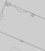


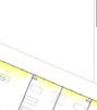


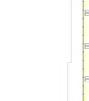


An indisputable feature of the complex is light. Since our main project is focusing on the shaping and the landscaping of the roof, we aimed to bring more natural light as possible inside the building, creating a glass skin all around our building, creating a needed atmosphere as well as adding quality to the internal spaces.

To ensure accessibility to light, several light analyses have been conducted. The one shown in those plans was conducted on the 21 June. For each level of the building, an inside light analysis has been done to know which areas and rooms do not need to during the day to switch on the artificial light and which ones instead could suffer, mostly during the hotter seasons, from too much direct light and therefore, suffering the heat.
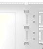


As can be seen from the plans under the analysis, the care centre at the north of the building, not the room next to the facade, and some offices in the recreation centre, both on the ground floor, need to switch on the artificial light, due to shape of the building and their inner position.


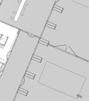


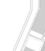


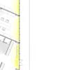


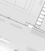


The light analysis can demonstrate the amount of penetration in different areas of the building. The main focus lies within the underground spaces, where the recreation centre, offices, ballroom and aquatic gym take space. It is important to see that all these places received an important amount of natural light, thanks to the glass facade and also to skylight places on the walkable roof.
Basement floor - Daily factor analysis


Ground floor - Daily factor analysis
2 9 10 10 11 11 12 12 14 14 15 15 B1 A A B B C C1 D D1 E E1 F1 F G H J K L M N O P R S T U V G1 H1 J1 L1 N1 P1 S1 Y Z AA AA BA BA CA CA DA DA EA EA 16 16 17 13 13 7 6 5 4 3 8 8 U1 1 Y1 Z1 11a 11a
2 9 10 10 11 11 12 12 14 14 15 15 B1 A A B B C C1 D D1 E E1 F1 F G H J K L M N O P R S T U V G1 H1 J1 L1 N1 P1 S1 Y Z AA AA BA BA CA CA DA DA EA EA 16 16 17 13 13 7 6 5 4 3 8 8 U1 1 Y1 Z1 11a 11a 109
First floor - Daily factor analysis
Solar analysis


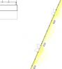


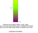


Second floor - Daily factor analysis


The movement of sun during the day is also analyzed and in each season of the year and observe the amount of light falling on each elevation of the complex to have a better comprehension of how much direct and indirect light can enter the building.


2 9 10 10 11 11 12 12 14 14 15 15 B1 A A B B C C1 D D1 E E1 F1 F G H J K L M N O P R S T U V G1 H1 J1 L1 N1 P1 S1 Y Z AA AA BA BA CA CA DA DA EA EA 16 16 17 13 13 7 6 5 4 3 8 8 U1 1 Y1 Z1 11a 11a 2 9 10 10 11 11 12 12 14 14 15 15 B1 A A B B C C1 D D1 E E1 F1 F G H I J K L M N O P R S T U V G1 H1 J1 L1 N1 P1 S1 Y Z AA AA BA BA CA CA DA DA EA EA 16 16 17 13 13 7 6 5 4 3 8 8 U1 1 Y1 Z1 11a 11 Solstice of June 21.11 Equinox of March 18.35 Equinox of September 19.25 Solstice of December 16.43 Solstice of June 05.33 Equinox of March 06.24 Equinox of September 07.06 Solstice of December 07.59 110
07Building Technology 7.2 Materials
As already seen, in our building, in the overground and outside areas, glass and wood overweight all the rest of the materials. Glass walls, doors of the entrance and other elements promote connectivity and create a direct visual connection, between the outside and inside. This connection is both tangible, visual, and physical, direct access. Wood, on the other hand, has a welcoming and warm touch to the rest of the environment. Referring back to the tradition in woodwork and their current green approach.
1- Structural system: by Arcelormittal
HEM 700 - IPE 330 (S235)
2- Structural system pavement: by Metecno
Corrugated sheet and concrete slab
Slab weight: 190 kg/m2
Slab height: 10 cm
3- Cork Insulation panel: by Edisughero
Thermal conductivity: 0.047 λ (W/mK)
Compression reistance: 30 kN/m2
Density: 180 kg/m3
Thickness: 6 cm
4- Lightened concrete screed: by Leca
Thickness: 10 cm
5- Dry floor heating sytem: by SolarCalor


6- Porcelain Stoneware wood: by Italgres
Size: 20 x 120 cm
Thickness: 6 cm
7- Response HG pavement: by AllsportsAmerica
Load capacity: 1.37 MPa
8- Microcement floors: by Idealwork
Thermal conductivity: 0.46 λ (W/mK)
Compression reistance: 13 MPa
Aquatic gym - Interior detail
Athletic gym - Interior detail
Common area - Interior detail
1 2
3 4 5 8 1 2 3 4 5 7 1 2 3 4 5 6
111
1- Structural system: by Arcelormittal
HEM 700 - IPE 330 (S235)
2- Structural system pavement: by Metecno
Corrugated sheet and concrete slab Slab weight: 190 kg/m2 Slab height: 10 cm
3- Cork Insulation panel: by Edisughero
Thermal conductivity: 0.047 λ (W/mK)
Compression reistance: 30 kN/m2 Density: 180 kg/m3 Thickness: 6 cm
4- Lightened concrete screed: by Leca Thickness: 10 cm
9- Water retention slab: by Italgranite
Weight: 5 kg/m2 Size: 57 x 38 cm Thickness: 10 cm
10- Intensive and extensive soil: by Leca
Weight 25 cm: 5 kN/m2 Weight 15 cm: 3 kN/m2
11- Granite Nordic stone: by Pierre & Sol Size: 30 x 10 cm Thickness: 2 cm
12- Grass, vegetation and plants: A selection of vegetation suitable for the green roofs and the climate of the city of Milan. Zone 8a: -12.2°C to -9.4°C
13- Larch wood shading system: by Apropositodilegno Size: 10 x 10 cm
14- Triple chamber glass: by Perfect view Uf glass: 0.7 W/m2K
15- FWS 50.SI green window frame: by Schuco Uf frame: 0.69 W/m2K
16- Steel profile: by Arcelormittal
Intensive green roof detail

Exstensive green roof detail

1 2 4 3 9 10
11 12 2
14 12 16 13
4 3 15 9 10 1
112
Design details

The integration between structural and architectural design deeply influences the design of façades. After a long exploration of different technological solutions, the one more coherent with our design was a unitised
curtain-wall system. Each unit is anchored to the corrugated sheet slabs using vertical mullions, detached by the structural elements (beams and columns), giving more freedom to the facade system.
Structural elements of the envelope detail Envelope detail
A B A B
07Building Technology 7.3
ground level 0 L. bulkhead -8450 basement level -5000 A B C D E F G H I J K L M N O P R S T U V Y Z AA BA CA DA EA first level 5000 second level 10000 roof level 17000
113


B4 In1 Csh Wm Ps ShW1 C4 GL1 TS ML SH IN1 DL WP VE SC CSH WM FH SH B5 DC Wp IN2 B3 DP Gl ML TS B4 C4 B1 A 6000mm C4 B4 IN1 CsH WM PS B1 GL2 Sr GL1 TS ML SH 114

07Building Technology
U V T S ground level 0 L. bulkhead -8450 basement level -5000 A B C D E F G H I J K L M N O P R S T U V Y Z AA BA CA DA EA first level 5000 second level 10000 roof level 17000 1 : 250 AA Section ST localisation drawing 1
115
U V S T ATHLETIC GYM SECONDARY ENTRANCE MAIN CIRCULATION PUBLIC PASSAGE GREEN ROOF AQUATIC GYM TECHNICAL SPACES
Structural elements of the envelope detail in the dilatation part Envelope detail in the dilatation part
The details displayed in these two pages show one problem we had to face regarding the structural composition of the building, the dilatation joints.
This particular feature is important when two complexes with different heights are adjacent to each other. The solution found was to create two different structures, slightly detached from each other but that could still work together.

SH C4 IN1 DL WP VE1 B1 SC CsH WM DP B5 DC FH GL1 ML TS B4 B3 BD ST IN1 DL WP VE2 B1 B4 IN CsH WM B4 IN1 SC WP N2 SR IN1 CsH WM PS U V HR SSC RD 3000mm DP SH C4 B1 DP B5 DC GL1 ML TS B4 B3 BD ST IN1 DL WP VE2 B1 B4 IN CsH WM B4 IN1 SC WP N2 SR IN1 CsH WM PS U HR SSC RD DP DP
116
Structure detail of the aquatic gym skylight
The composition of the skylights required several thinking regarding the structural components of the elements and their design composition. Since it was not possible to cut and interrupt any primary beams of the aquatic gym, the
position of those elements had to be placed between two primary beams.
In addition, two tubular profiles have been added to support the movement of the ground on top of the skylight.
Aquatic gym roof parapet detail
B2 C4 SSH B4 B6 FH RG FH B1 2762 mm DL VE1 RB WP LN1 LN1 SC CSH WM RP 07Building Technology u d e 0 e b h a -8 5 e e a a n e e -6 5 a m e -5 0 e 5 0 c n e e 1 0 0 o e e 1 0 0 o o 8 0
117
B2 B2 B4 C4 C4 B6 B6 B7 GL2 ST ST DL DL AS WP RB VE2 IN1 IN1 VE2 RB WP IN1 IN1 SC SC CSH WM CSH WM VE2 RB WP DL IN1 IN1 SC FH FH IN2 IN1 D1 E1 5523 mm 5523 mm CSH DP RP RP Aquatic gym Skylight Detail 118
There are two types of foundations with igloo and gravel. Under the technical spaces due to heavy machinery it is not proper to use light
igloo elemans. For this reason, in these places gravel is used as material between foundation beams. In other spaces igloos are used.
07Building Technology Foundation Details
CV Wp FP FL C1
Fp2
-5000 -6500 -6000
Fb Wp
FP FL WP
Fb Gr Wp Fp2
A6000mm
C1 A
6000mm
119

120
- CHAPTER 8 -
Building System
08.1 - Heat load 08.2- HVAC system 08.3- Water supply sytem 08.4- Water sewage system
Building
8.1 Heat load
The Heat Load analysis is a set of theoretical and practical knowledge that helps us to obtain the amount of power needed to sustain the building during the winter and the summer seasons. In these cases, we are considering the worst-case scenarios to be able to estimate as accurately as possible. All the calculations have followed the code UNI 7357/1974.
Regarding the calculation of the Winter Heat Load concerning the design temperature, for the external one, the value of -5°C has been chosen, while for the internal one, a value of 20°C has been adopted for the entire building. Some simplifications were introduced to ease the calculation; first of all, the building has been split into different parts based on the programme and configuration of the building, in each box slabs and partitions were considered
neglected and in the interface between the boxes, no heat flux flows since the same internal design temperature has been adopted for all of them.
The division of the structure has been decided and chosen according to the configuration of the building and also based on the differences of the characteristics of the envelope.
Winter Heat Load Calculation:
QHL,i = QT,i + QV,i + QHU,i QHL,i = Total dispersion (W) QT,i = Thermal dispersion by transmission (W) QV,i = Thermal dispersion by ventilation (W) QHU,i = Extraction power needed for compensating the effects of the intermitting heating (W)
08-
System
WALKABLE GREEN ROOF
123
NOT - WALKABLE GREEN ROOF
Our building envelope is composed mainly of two different parts: one is the glass facade, on which the outside is applied our shading system, which is not taken into consideration for the calculation; the second one is the opaque layering of the roof, which we distinguish in walkable green roof and not a walkable one.
A third party alto part is taken into account, the foundation one, which is the one in contact with the earth underground.
The most relevant property of the materials we are going to focus on is the thermal transmittance of each surface (U); it is calculated as the reverse of the thermal resistance (R) of each layer of the Slab.
The thermal resistance of a layer is given by the thermal conductivity of its material divided by its thickness or is measured and provided by the producers. It is worth pointing out that thermal bridges have been neglected during our computations.
Vertical element: The main facade it is composed by a Triple Glass low-e, Solar control : 4 mm glass + 16 mm Argon + 4 mm glass + 16 mm Argon + 4 mm glass
Total thickness: 44 mm
value: 0.7 W/m2*K
Horizontal envelope - Not walkable green roof
U (W/m2*K): 0.119 W/m2*K
Horizontal envelope - Walkable green roof
U (W/m2*K): 0.117 W/m2*K
Horizontal envelope - Foundation slab
U (W/m2*K): 0.575 W/m2*K
U
Winter Heat Load 100 5,5 10 10 14 8 15 57 100 5,5 10 10 14 8 25 72 5 10 20 60 10 5 2
124
Winter Heat Load Calculation
QT,i = Thermal dispersion by transmission torward exterior and ground (W)
QT,i,e= Σ((ei*Ai*Ui)*(Ti -Te)) + ((ei*Li*Ψi)*(Ti - Te))
QT,i,g = G w *Σ(Ai*Ui*f g 1 + f g 2*(Ti -Te))
- ei: exposition factor
- Ai: area of the surface torwards a certain exposition
- Ui: trasmittance of said surface - Li: lenght of the thermal bridge
- Ψi: thermal bridge coefficient depending on the typology
- Ti: internal design temperature - Te: External design temperature
- Gw: correcting factor that takes into account the presence of under-ground water
- fg1: correcting factor that takes into account the variation of external temperature - fg2: correcting factor that takes into account the annual variation of external temperature
Not Walkable green roof: - North/West: 14.7 kW - North/East: 6.56 kW - East: 23.3 kW - South/West: 5.5 kW - Roof: 9.42 kW - Ground: 24.5 kW
- Total: 84.02 kW
Walkable green roof: - North/West: 2.89 kW - West: 7.45 kW - North: 3.971 kW
- South/East: 5.77 kW - Roof: 15.2 kW - Ground: 37.76 kW - Total: 73.06 kW
QV,i = Thermal dispersion by ventilation (W)
QV,i= Σ ((V*n)/3600]*p*Cp*(Ti - Te))
- V: total volume of the room (in this simplified study, the volume of the interal spaces) - n: air change per hour. It is an adimensional value between 0.5 and 2 and was q chosen from values provided in a table in the UNI EN 10339 - p: dry air density (1.225 kg/m3) - Cp: air specific heat (1005 J/kg*K) - Ti: internal design temperature - Te: External design temperature Entire complex: - Total: 253.33 kW
QHU,i = Extraction power needed for compensating the effects of the intermitting heating (W)
QHU,i = Σ (Ai*Ф hu,i)
- Ai: total area of the room (in this simplified study, the area of the interal spaces) - Ф hu,i: specific heating - up power found in the table in the UNI EN 10339 - (18) Entire complex: - Total: 143.77 kW
Total Winter Heat Load:
QHL,i = QT,i + QV,i + QHU,i
QT,i: 157.08 kW QV,i: 253.33 kW QHU,i: 143.77 kW
Total: 554.18 kW
08Building System 125
Summer Heat Load
The Summer Heat Load is an estimation of the amount of Heating that the Cooling system has to provide to the building under the design boundary conditions. The calculation has been performed following the simplified Carrier methods.
Concerning the design temperature, for the external one, the value of 32°C has been chosen, while for the internal one, a value of 20°C has been adopted for the entire building. Following the Carrier Method, the distinction between Sensible and Latent heat is taken into account.
Sensible heat load is considered in a transient state, which means that calculations must be done for every daily hour.
Sensible heat includes different contribution: - Conduction through opaque structures toward external, unconditioned or conditioned spaces; - Conduction through transparent structures - Radiation through transparent surfaces - Ventilation - Internal load
General Data:
- External Design temperature: 32° C
- Daily Thermal Excursion (DTe): 12° C
- Maximum external absolute humidity: 14.4g/kg
- Latitude : 45°
- Longitude: 27’
- Internal Design temperature: 20° C
- Design Internal humidity: 12.7 g/kg
- Mass in plan: 450 kg/m2
- Air flow rate: 103791.6 m3/h
Summer Heat Load data
NORTH 0.1
- Up: trasmittance of the opaque structures previously calculated
- Uf: trasmittance of the transparent surfaces previously calculated
- f: fraction of glass area, calculated as follow: (Area glass/(Area glass + Area frame))
- F: solar factor obtained by multipying the shading coefficient (SC = 0.71 for triple glass panel) times solar factor for single glass (Fvs = 1.15)
- Sf: area of transparent surfaces
- Te: External design temperature
Up Mf,p** Sp UF f F=SC Fvs SF W/(mq K) kg/mq mq W/(mq K) - - mq
Exposition
116 0.0
116 0.0
116 0.0
116
520 0.0
400 0.0 Opaque Surfaces Transparent Surfaces
0.8 0.7 0.82 466.635 EAST 0.1
0.8 0.7 0.82 1336 WEST 0.1
0.8 0.7 0.82 1135.4 SOUTH 0.1
0.0 0.8 0.7 0.82 281.75 HORIZONTAL - SHADED 0.604
ORIZZONTALE SOLE 0.114
126
Internal Load
Internal Loads are divided into their Sensible and Latent Components, and each of these two categories is divided into their Permanent and Variable contributions.
Permanent internal loads are generated by electrical devices. The estimated value for these contributions is again found in Tables from UNI 7357/1974. The amount and type of device have been estimated based on the layout and programme of the typical floor plan of the two blocks.
Variable internal loads are generated on the heat by the people inside the building and the kind of activity.
For the estimation of the Summer Heat Load, taking in consideration the programme of the building, all the people and the electronic devices have been calculated according to the timing of the activity:
- Theater: hour 19 - 24 - Cinema: hour 12 - 24 - Pool & Gym: hour 9 - 24, for every hour a % estimation of the number of people has been calculated
- Offices: hour 9 - 18 - Care center : hour 9 - 18 - Basketball court: hour 17 - 22 - Ball Room: hour 21 - 24
SENSIBLE HEAT LOAD
SPACE A (m2) Indix pp N PERSONEW/PP
TEATRO 315 108 65 CINEMA 315 108 65 PALESTRA 1 862 0.5 431 210 PALESTRA 2 937.5 0.5 468.75 210 PISCINA 1300 0.3 390 210 UFFICI 736 0.12 88.32 70 BALL ROOM 525 1 525 210 BASKET 836.7 0.5 418.35 210 CARE CENTER 700 0.12 84 90
LATENT HEAT LOAD
SPACE A (m2) Indix pp N PERSONEW/PP
TEATRO 315 108 45 CINEMA 315 108 45 PALESTRA 1 862 0.5 431 450 PALESTRA 2 937.5 0.5 468.75 450 PISCINA 1300 0.5 650 450 UFFICI 736 0.12 88.32 65 BALL ROOM 525 0.5 262.5 450 BASKET 836.7 0.5 418.35 450 CARE CENTER 700 0.12 84 65
SENSIBLE HEAT LOAD
DEVICES N APP N PERSONE
TEATRO 550 108 CINEMA 550 108 PALESTRA 1 0 431 PALESTRA 2 0 468.75 PISCINA 0 390 UFFICI 90 88.32 BALL ROOM 0 525 BASKET 0 418.35 CARE CENTER 90 84
LATENT HEAT LOAD
DEVICES N APP N PERSONE
TEATRO 550 108 CINEMA 550 108 PALESTRA 1 0 431 PALESTRA 2 0 468.75 PISCINA 0 650 UFFICI 550 88.32 BALL ROOM 0 262.5 BASKET 0 418.35 CARE CENTER 550 84
08-
System
Building
127
To have a precise value for the Summer Heat Load, the airflow rate has to be taken in consideration, which is calculated multiply the total number of people the building can host (2621) by the airflow needed for each person (39.6 m3/h) F: 103791.6 m3/h
The Summer Heat Load will be a sum of the Maximum value found of the Sensible Heat and the maximum value of the Latent Heat.
Internal Load calculation
Internal Load
Fixed Sensitive Internal Load Qint,s,cost 3600 W
Fixed Latent Internal Load Qint,l,cost 3900 W
Total fixed Load Hour Fixed Variable Fixed Variable H Qint,s,cost Qint,s,var Qint,l,cost Qint,l,var h W W W W 8 3600 188947.5 3900 404887 9 3600 104830 3900 173805 10 3600 104830 3900 173805 11 3600 123724 3900 214294 12 3600 180409 3900 335760 13 3600 218198 3900 416738 14 3600 140742 3900 426188 15 3600 150189 3900 264233 16 3600 112400 3900 183255 17 3600 275832 3900 452490 18 3600 408096 3900 816889 19 3600 443099 3900 1009485 20 3600 386414 3900 875871 21 3600 254151 3900 564108 22 3600 178572 3900 385958 23 3600 90791 3900 197700 24 3600 52929 3900 108625
Total Summer Heat Load: Max Sensible Heat Load: 782.1633 kW
Max Latent Heat Load: 1160.482 kW
Total Summer Heat Load: 1942.645 kW
128
HVAC System
The HVAC (Heating, Ventilation, Air Cooling) system of a complex is extremely important in contemporary buildings and needs to be designed carefully because it is linked with the well-being of its users since it controls the quality and the temperature of the indoor air.


For our building, an all-air system was chosen, which consists of the machinery and also Ducts (return, supply and exhaust). According to the layout and the programme inside the building, a subdivision in 6 major areas was done. Each of these blocks was assigned one AHU (Air Handling Unit) that generates, gathers, filters
and distributes the air and a single Heat Pump was installed in the Underground plan of the building, sustaining all the AHUs.
The AHUs, all placed at the basement level of our building, distributes treated air on the building with a primary system of ducts that pass through the building from bottom to top in the designated shafts. Exhaust indoor air is extracted from the room, partially re-treated and partially expelled outside. The design process has been made following the UNI CODE 10339 standards.
08Building System
8.2
Filter Cooling coil Heating coil Rerurn Air Air Handling Unit or AHU Air Circulating Fan Fresh Treated Air Ventilated Room Outside Air Hot Water In Hot Water Out Chilled Water Out Chilled Water In Heat Pump Outside Air applications Size Airflow (m3/h) Height - mm Width - mm 12 29,800 1,690 2,480 13 33,800 1,870 2,510 14 43,200 1,990 2,940 15 51,000 2,110 3,230 NXW 0503 - 1654 ■ Per i modelli che rientrano nelle detrazioni e negli incentivi fare riferimento solo alle liste presenti sul sito www.aermec.it Pompa di calore condensata ad acqua reversibile lato acqua Potenza frigorifera 111 ÷ 511 kW Potenza termica 127 ÷ 582 kW • Versatilità d'installazione anche per applicazioni geotermiche. • Possibilità di avere da 1 a 2 pompe sia sul lato sorgente che sul lato utenza. • Reversibile in pompa di calore sul lato idraulico.
Air Handling Unit Heat Pump 129
HVAC system
Supply air HVAC System - Basement floor Return air Exhaust air Drainage system Hot water Cold water 4197 2 9 10 10 11 11 12 12 14 14 15 15 B1 A A B B C C1 D D1 E E1 F1 F G H I J K L M N O P R S T U V G1 H1 J1 L1 N1 P1 S1 Y Z AA AA BA BA CA CA DA DA EA EA 16 16 17 13 13 7 6 5 4 3 8 8 U1 1 Y1 Z1 11a 11a 130
Ventilation rate
Following the UNI 10339, we managed to design the ventilation rate needed to supply air to the indoor spaces.
After calculating the area and volume of the served spaces, each function was assigned a crowding rate value and an airflow volume value, both picked from the regulation tables. It was then defined the maximum number of people using the building and the ventilation rate per person. Multiplying these two values for each space, the total airflow volume was found and it was later used to dimension the duct sections for each area.
Ventilation rate
To size the air ducts, an Air Velocity Method was adopted. For each duct segment, a maximum air velocity was chosen, and considered constant; in its function of it, the dimension of each duct section was defined. To simplify the process, the pressure drops were assumed constant as well. With attention to comfort requirements, for the primary system ducts, a velocity of 7 m/s was chosen.
The ducts will be rigid and will have a rectangular section that changes according to the needs of the layout of the building.
SPACE A (m2)
A (m2)
Volume Crowding rate N People Air flow volume
Ventilation rate Air flow Volume Ventilation rate [m2] [m3] [l/s per person] [m3/h per person] [m3/h] [m3/s]
Air flow volume Ventilation rate Air flow Volume [m2] [m3] [l/s per person] [m3/h per person] [m3/h]
Volume Crowding rate N People
315 1260 - 108 5.5 19.8 2138.4 0.594 315 1260 - 108 5.5 19.8 2138.4 0.594 862 4310 0.5 431 16.5 59.4 25601.4 7.1115 937.5 4687.5 0.5 468.75 16.5 59.4 27843.75 7.734375 1300 13000 0.3 390 16.5 59.4 23166 6.435 736 3680 0.12 88.32 11 39.6 3497.472 0.97152 525 4725 1 525 5.5 19.8 10395 2.8875 836.7 10040.4 0.5 418.35 16.5 59.4 24849.99 6.902775 700 3500 0.12 84 11 39.6 3326.4 0.924 1440 9360 0.5 720 11 39.6 28512 7.92
THEATER 315 1260 - 108 5.5 19.8 2138.4
CINEMA 315 1260 - 108 5.5 19.8 2138.4
GYM 1' 862 4310 0.5 431 16.5 59.4 25601.4 GYM 2' 937.5 4687.5 0.5 468.75 16.5 59.4 27843.75 POOL 1300 13000 0.3 390 16.5 59.4
OFFICES 736 3680 0.12 88.32 11 39.6 3497.472 BALL ROOM 525 4725 1 525 5.5 19.8 BASKETBALL COURT 836.7 10040.4 0.5 418.35 16.5 59.4 24849.99
CARE CENTER 700 3500 0.12 84 11 39.6 3326.4 LOBBY 1440 9360 0.5 720 11 39.6
Volume Crowding rate N People Air flow volume Ventilation rate Air flow Volume Ventilation rate [m2] [m3] [l/s per person] [m3/h per person] [m3/h] [m3/s] 315 1260 - 108 5.5 19.8 2138.4 0.594 315 1260 - 108 5.5 19.8 2138.4 0.594 862 4310 0.5 431 16.5 59.4 25601.4 7.1115 937.5 4687.5 0.5 468.75 16.5 59.4 27843.75 7.734375 1300 13000 0.3 390 16.5 59.4 23166 6.435 736 3680 0.12 88.32 11 39.6 3497.472 0.97152 525 4725 1 525 5.5 19.8 10395 2.8875 COURT 836.7 10040.4 0.5 418.35 16.5 59.4 24849.99 6.902775 CENTER 700 3500 0.12 84 11 39.6 3326.4 0.924 1440 9360 0.5 720 11 39.6 28512 7.92
Regarding the space of the Aquatic gym, since it’s hosting the pools it needs to have its own AHU, because we are working with different humidity and temperature compared to the building and therefore also the ducts bringing air inside are working only for that space.
Considering a ventilation rate of 6.435 m3/h and air velocity inside the ducts of 7 m/s, the area required for the ducts of the Aquatic gym is Ad: 0.45 m2; therefore the main duct pushing the air needs to have a section of 80 x 60 cm.
08-
Building System
e
131
HVAC System - Ground floor Return air Exhaust air Drainage system Hot water Cold water 2 9 10 10 11 11 12 12 14 14 15 15 B1 A A B B C C1 D D1 E E1 F1 F G H I J K L M N O P R S T U V G1 H1 J1 L1 N1 P1 S1 Y Z AA AA BA BA CA CA DA DA EA EA 16 16 17 13 13 7 6 5 4 3 8 8 U1 1 Y1 Z1 11a 11a 132
Supply air
08Building System
8.3 Water Supply
The water supply system of the project is anticipated to be connected with the Municipality Water Network. Other backup sources, used for sanitary appliances can be found within the building from rainwater collectors.
To fit the project into the system of the city the UNI CODE 9182 standards and the UNI EN 806-2 standards have been followed. We are involving the Cold water distribution grid along with a separate Hot water grid which is composed of piping, control valves, pressurization and arrogation parts at the top of the supply to regulate water flow that needs to be calculated.
After consideration of applying a Top Up system for cold water distribution, we have decided to not implement Rain Water into the general supply system. This is the result of safety
Cold Water Loading Units and Diameters
OUTLETS
reasons as we are building a highly complex Research centre, which has to avoid any sort of contamination.
The Bottom Up Hot water distribution system is based on placing the recirculation and supply manifolds placed on the underground level. Following the charts of the UNI code, we estimated the minimum storage of water according to the maximum outcome of people inside the complex.
Recirculation
Local supply
n LU SUM LU
WC 4 1 4 Shower 8 2 16 Wah basin 4 1 4
TOTAL LU TYPICAL FLOOR 24 28 mm DN n. FLOOR 3
TOTAL LU VERTICAL UNIT 72 35 mm DN
Hot Water Loading Units and Diameters
OUTLETS
n LU SUM LU
WC - 1Shower 8 2 16 Wah basin 4 1 4
TOTAL LU TYPICAL FLOOR 20 22 mm DN n. FLOOR 3
TOTAL LU VERTICAL UNIT 60 35 mm DN
The UNI code provides for each outlet inside the building a specific Loading Unit that needs to be applied for each of that. The sum of all these outlets distributed all over the building
gives an estimation of the Loads and litres of water that the building needs for everyday use. The material chosen for the piping system is a multi-layered plastic material.
133
HVAC System - First floor
Exhaust air Drainage
Hot water Cold water 2 9 10 10 11 11 12 12 14 14 15 15 B1 A A B B C C1 D D1 E E1 F1 F G H I J K L M N O P R S T U V G1 H1 J1 L1 N1 P1 S1 Y Z AA AA BA BA CA CA DA DA EA EA 16 16 17 13 13 7 6 5 4 3 8 8 U1 1 Y1 Z1 11a 11a 134
Supply air
Return air
system
8.4 Water Sewage System
The sewage net is discharged underground and connected to the local sewage system that connects our building to the rest of the city model. The main concept is to divide the drain into 2 components, which means it is a separated system. It is based on Waste Water and Rain drain.
Splitting each system will allow the reuse of rainwater and implementation into a separate water supply leading to gardening support. Systems are discharged under the lowest basement level.
For the design of the Drainage system, the EN 12056-2 code has been used. The system which has been chosen for the project is System 2 to have a greater capacity to serve quantities of spaces simultaneously and has long pipe segments.
The system has been divided into 6 subsystems, with 6 different columns inside the building and 5 collectors.
The material used for the pipes is PVC.
For each sewage column, the outlets are taken into consideration and the sum of the Loading Units for each of these outlets.
System II: Single discharge stack system with small bore discharge branch pipes.
Sanitary appliances are connected to small bore branch discharge pipes. The small bore branch discharge pipes are designed with a filling degree of 0.7 (70%) and are connected to a single discharge stack.

The method used for sizing the pipes is the one suggested in the UNI EN 12056-2.

The waste water flow rate has been calculated with the following formula: Q ww = k*e(Σ DU)
Q ww : waste water flowrate (l/s) k: frequency factor Σ DU: sum of the discharge units

08Building System
Frequency Factors Reference Table EN 12056 - 2 135
Discharge Units Reference Table EN 12056 -2


Horizontal branches limitations Reference Table EN 12056 -2
Vertical stacks Table EN 12056 -2
Local Sewer Rain water Cleaning system Rain water tank Gardening - Sanitary water supply Rain water
136
Water Sewage system scheme
Water Sewage Column - 1
As already mention, to establish the diameter for the column pipe, we need to calculate Waste Water Flowrate for each outlet of each floor connected to the column.

Here we are going to show the calculation for one of the biggest columns, which is attached to three bathrooms on three different floors, the Aquatic gym in the basement, the care center on the ground floor and fitness gym on first floor
Basemente level - WC 7 1.8 1 12.6
Basemente leve - Wash Basin 7 0.3 1 2.1
Ground level - WC 5 1.8 1 9
Ground level - Shower 10 0.5 1 5
Ground level - Wash basin 4 0.3 1 1.2
First level - WC 5 1.8 1 9
First level - SHower 10 0.5 1 5
First level - Wash basin 4 0.3 1 1.2 SUM Σ DU 45.1 Q ww = e(Σ DU) = e45.1 = 6.715 (l/s)
Column DN: 150 mm
Drains DN: 250 mm Drains Slope: 3 cm/m Drains velocity: 2.2 m/s
Horizontal drains collectors Reference Table EN 12056 -2
OUTLETS (Aquatic gym, care center, fitness gym) n DU k Σ DU
08Building System 137
Water Sewage Column - 2, 3
As already mentioned, to establish the diameter for the column pipe, we need to calculate Waste Water Flowrate for each outlet of each floor connected to the column.
Here we are going to show the calculation for two big columns, which are attached to three
bathrooms on three different floors, the Aquatic gym in the basement, the athletic gym on the ground floor and the fitness gym on the first floor and collect in one single drain.
OUTLETS (Aquatic gym, athletic gym, fitness gym) n DU k Σ DU
Basemente level - WC 7 1.8 1 12.6
Basement level - Shower 8 0.5 1 4
Basemente level - Wash Basin 7 0.3 1 2.1
Ground level - WC 6 1.8 1 10.8
Ground level - Shower 8 0.5 1 4
Ground level - Wash basin 5 0.3 1 1.5
First level - WC 4 1.8 1 7.2
First level - SHower 8 0.5 1 4 First level - Wash basin 4 0.3 1 1.2
SUM Σ DU 47.4
OUTLETS (Athletic gym) n DU k Σ DU
Ground level - Shower 6 0.5 1 3 Ground level - Wash basin 6 0.3 1 1.8 Ground level - WC 6 1.8 1 10.8
SUM Σ DU 15.6
Qww2 = e(Σ DU) = e47.4 = 6.884 (l/s)
Qww3 = e(Σ DU) = e15.6 = 3.95 (l/s)
Qwwtotal: = e(Σ DU) = e62.6 = 7.91 (l/s)
Column DN: 150 mm
Drains DN: 300 mm Drains Slope: 2 cm/m Drains velocity: 2.0 m/s
138
Water Sewage Column - 4,5,6
As already mentioned, to establish the diameter for the column pipe, we need to calculate Waste Water Flowrate for each outlet of each floor connected to the column. Here we are going to show the calculation for
OUTLETS (Lobby and gym)
the last small column and drains, which collect the water sewage from the lobby, gym on the ground floor, the recreation centre and staff bathroom at the basement level.
n DU k Σ DU
Ground level - Shower 8 0.5 1 4
Ground level - Wash basin 30 0.3 1 9 Ground level - WC 26 1.8 1 46.8
SUM Σ DU 59.8
Q ww = e(Σ DU) = e59.8 = 7.73 (l/s)
Column DN: 150 mm
OUTLETS (Recreation center)
Drains DN: 300 mm Drains Slope: 2 cm/m Drains velocity: 2.0 m/s
n DU k Σ DU
Ground level - Shower 0 0.5 1 0 Ground level - Wash basin 9 0.3 1 2.7 Ground level - WC 11 1.8 1 19.8
SUM Σ DU 22.5
Q ww = e(Σ DU) = e22.5 = 4.74 (l/s)
Column DN: 125 mm
OUTLETS (Staff bathroom)
Drains DN: 200 mm Drains Slope: 2.5 cm/m Drains velocity: 1.7 m/s
n DU k Σ DU
Ground level - Shower 0 0.5 1 0
Ground level - Wash basin 6 0.3 1 1.8 Ground level - WC 6 1.8 1 10.8
SUM Σ DU 12.6
Q ww = e(Σ DU) = e12.6 = 3.55 (l/s)
Column DN: 125 mm
Drains DN: 200 mm Drains Slope: 1 cm/m Drains velocity: 1.1 m/s
08Building System 139
HVAC System - First floor
Exhaust air Drainage
Hot water Cold water 2 9 10 10 11 11 12 12 14 14 15 15 B1 A A B B C C1 D D1 E E1 F1 F G H I J K L M N O P R S T U V G1 H1 J1 L1 N1 P1 S1 Y Z AA AA BA BA CA CA DA DA EA EA 16 16 17 13 13 7 6 5 4 3 8 8 U1 1 Y1 Z1 11a 11a 140
Supply air
Return air
system
- CHAPTER 9 -
CONCLUSION
In Milano Innovation District, different kinds of facilities are involved such as mixed-use buildings, commercial, education, health, labratory, and residential buildings. Inside the new district, entertainment facilities are not well developed to offer a space for leisure, free time,
To lay out an embrace of nature, the permeability of the building between the interior and exterior is proposed with the idea of integration of the landscape.
The linear park coming from Decumano continues through the roof called the green

09-Conclusion

- CHAPTER
10 -
Bibliography & Sitography
Arexpo, pwc, Roland Berger (2016), Milan. Guidelines for the Arexpo strategic development and enhancement plan
Arexpo (2018), Milan. Thematic park, Human Technopole: the new headquarters
Arexpo (2018), Milan. Guidelines, Human Technopole: the new headquarters
Arexpo, Lendlease, Aecom, Land, Systematica, Carlo Ratti Associati (2019), Milan. Accessibility study from west gate to the municipality of Rho, MIND: Regeneration project for sustainable urban development
Arexpo, Lendlease, Aecom, Land, Systematica, Carlo Ratti Associati (2019), Milan. Landscape report, attachment n.3, environmental Impact Study, MIND: Regeneration project for sustainable urban development
Arexpo, Lendlease, Aecom, Land, Systematica, Carlo Ratti Associati (2019), Milan. Strategic environmental assessment of the integrated post-expo intervention program, MIND: Regeneration project for sustainable urban development
Arexpo, Lendlease, Aecom, Land, Systematica, Carlo Ratti Associati (2019), Milan. Integrated program of intervention – final proposal, MIND: Regeneration project for sustainable urban development
Arexpo (2019). Relazione Paesaggistica
Arexpo (2020), Milan. Enhance Covert Innovate
CRA – CARLO RATTI ASSOCIATI (2018), Science for Citizens. The Science Campus of the University of Milan in MIND (Schematic Design)
CRA – CARLO RATTI ASSOCIATI (2017), Milan Science & Innovation Park. Master plan
International Design Competition, Human Technopole: the new Headquarters for the design of the new headquarters of Fondazione HT, located in MIND – Milano Innovation District
Lendlease (2020), Milan. MIND Workplace Experience Strategy
Lendlease (2020), Milan. MIND West gate competition design brief MIND (2019), Milan. Innovation agenda for MIND – Life Sciences• MIND (2019), Milan. Welocome to MIND: a strategic project for Lombardy and Italy
Cichella S., (2008). Expo e post-Expo : analisi e progetto sul tema del riutilizzo del sito della Expo di Milano del 2015. Milano: Politecnico di Milano Corsi E., (2012). Milano 2016: la nuova veste del villaggio Expo Dezza, P. (2022), Lendlease ed Equiter per la Statale di Milano, Il sole 24 ore - Real Estate Pileri P., (2011). Spazi aperti: un paesaggio per Expo. Milano: edizione Electa Romano M., & Turri D., (2016). La via di Expo. (Ri)progettazione dell’area di Expo Milano 2015 Selleri B., & Zagari F., (2015). Moving forest Expo Milano 2015 landscape. Melfi: editore Libria Seema, A., John, P. (2016), Public-private partnerships for future urban infrastructure, Proceedings of the Institution of Civil EngineersManagement, Procurement and Law, Vol. 169, pp. 150 – 158.
Tingting, L., Sherif, M., Sherif, M., Tuan, S. N. (2021), Emerging themes of public-private partnership application in developing smart city projects: a conceptual framework, Built Environment Project and Asset Management, Vol. 11, pp. 138 – 156.
Università degli Studi di Milano, The new University Campus in Mind” Visconti, R.M., Martiniello, L., Morea, D., Gebennini, E. (2019), Can public-private partnerships foster investment sustainability in smart hospitals?, Sustainability, Vol. 11, pp. 1 – 19.
Vecchi, V., Casalini, F. (2019), Is a social empowerment of PPP for infrastructures delivery possible?, Annals of Public and Cooperative Economics, pp. 353 – 369
10-Bibliography & Sitography
Bibliography
MIND
EXPO 149
Scıence, Knowldege and Innovatıon Dıstrıct and Campus
Curvelo Magdaniel, F. (2016), Technology campuses and cities. A study on the relation between innovation and the built environment at the urban area level, (A+BE I Architecture and the Built Environment), TU Delft Open, Delft.
Hoeger, K., & Bindels, E. (2007), Campus and the city: urban design for the knowledge society, gta Verlag, ETH Zurich, Zurich.
Katz, Bruce, Wagner Julie, The Rise of Innovation Districts: A New Geography of Innovation in America, Metropolitan Policy Program at Brookings.
MIT School of Architecture and planning (2011), Innovation Technology Innovation Park. A research Study: Nandasoft Innovation Technology Development Park, Massachusetts Institute of Technology School of Architecture and Planning, Cambridge.
Moodysson, J., & Jonsson, O. (2007), Knowledge collaboration and proximity the spatial organization of biotech innovation projects. European urban and regional studies, 14(2). Russell, J. S. (1992), The New Workplace, Architectural Record, June 1992.
Urban Design
Balmori S., & Sanders J., (2011). Groundwork: Between Landscape and Architecture, The Monacelli Press
Bianchini F., & Hewage K. (2012). Building and Environment - How “Green“ are the green roofs? Lifecycle analysis of green rood material, 48, 57 - 65
Corner J., (2012), Lotus - High Line Section 2, 150, 25 -27
Corner J., (2014), The Landscape Imagination, Princeton Architectural Press
Maroni S., (2010) Mega eventi modificazioni urbane. Il ruolo delle grandi Esposizioni Universali nei processi di riqualificazione e rigenerazione urbana : un’opportunità per Milano. Milano: Politecnico di Milano
Landscape architecture European foundation, (2009). On Site: landscape architecture Europe. Basel: edizione Birkhäuser Merkel J., (2007). Architectural Design - Weiss/Manfredi Architects, 77, 104 - 111
Repishti J., (2009), Lotus - Scavo e sovrapposizione/Excavation and Superimposition, 139, 114 - 121
Register R., (1987). building cities for a healthy future, Berkley: edizione North Atlantic books Secchi B., & Viganò P., (2012), Lotus - Spoornoord Parc, 150, 102 - 113
Recreational Centers
Asensio Cerver F., & Duenas A., (1994), World of environmental design: Landscape of recreation 1. (Sports facilities), Arco Editorial, Barcelona
Diedrich R.J., (2005), PBuilding type basics for recreational facilities, Wiley, Hoboken
Geraint J., & Heard H., (1981), Handbook of sports and recreational building design / The Sports Council, Technical unit for sport, The architectural press. London
Raslanas S., & Stasiukynas A., (2013), Procedia EngineeringSustainability Assessment Studies of Recreational Buildings, 57, 929 - 937
Construction Design
Gonalves, C., & Margarıdo, F., (2015), Materials for Construction and Civil Engineering (Science, Processing and Design), Springer, Berlino - Heidelberg
Gauzın-Muller, D. (2002), Sustainable architecture and urbanism: concept, technologies, examples, Birkhauser, Basel-Berlin-Boston Khatıb, J.M. (2016), Sustainability of Construction Materials, Woodhead Publishing Series in Civil and Structural Engineering 70 (second edition)
Lyons, A., (2006), Materials for Architects and Builders, ButterworthHeinemann, Oxford
Zımmermann, A. (2009), Constructing Landscape: Materials, Techniques, Structural components, Birkhauser, Basel
150
Raitano P., La terra prima di Expo, Altraeconomia https://altreconomia.it/la-terra-prima-di-expo/ Han S., Second Stage of Hangzhou Cloud Town Exhibition Center, Archdaily: https://www.archdaily.com/903443/second-stage-ofhangzhou-cloud-town-exhibition-center-approach-design Di Marzo C., Presentato il masterplan del MIND - Milano Innovation Distric, Archiportale: https://www.archiportale.com/news/2022/07/ architettura/presentato-il-masterplan-del-mind-milano-innovationdistrict_89590_3.html
The cloud town conventıon and exhıbıtıon center (phase ıı),hangzhou,chına, Architecture Prize: https://architectureprize.com/ winners/winner.php?id=3461
Mind. Trasformare in realtà una visione per il paese, Arexpo: https:// www.arexpo.it/mind/ Milan’s Science & Innovation Park, Carlo Ratti: https://carloratti.com/ project/milans-science-knowledge-and-innovation-park/ Astbury J., Approach Design covers convention centre in Hangzhou with a sports park, Dezeen: https://www.dezeen.com/2019/04/21/ approach-design-hangzhou-cloud-town-exhibition-centre-greenroof-sports/
Guzzini G., Expo 2015: il Masterplan, Domus Web: https://www. domusweb.it/it/notizie/2009/09/09/expo-2015-il-masterplan.html
28 Ottobre: “Community Park in MIND” evento in presenza , Fondazione Triulza: https://fondazionetriulza.org/28-ottobrecommunity-park-in-mind-evento-in-presenzia/ Ruffolo E., Innovazione e sostenibilità: la strategia energetica del distretto MIND, Icona Clima: https://www.iconaclima.it/sostenibilita/ mind-milano-innovazione-sostenibilita/ Zorloni L., Dopo Expo, Matteo Cabassi: “Dieci anni per il futuro delle aree” Il Giorno: https://www.ilgiorno.it/bergamo/cronaca/expocabassi-1.1659792
Mancini G., Il futuro di Expo si chiama «Mind»: nasce il Milano Innovation District, Il Sole 24 Ore: https://www.ilsole24ore.com/art/ il-futuro-expo-si-chiama-mind-nasce-milano-innovation-districtAEVcLnNE
MIND Innovation District - Milan, IT, Land: https://www.landsrl.com/ portfolio-land/mind-innovation-district ll Masterplan di MIND – Milano Innovation District , Mario Cucinella: https://www.mcarchitects.it/progetti/ll-masterplan-di-mind-milanoinnovation-district
Merlata Bloom Milano, Merlata Bloom: https://www. merlatabloommilano.com/ Milan Innovation District, MindMilano: https://www.mindmilano.it/ EX.CA.VA, Park Associati: https://parkassociati.com/en/projects/exca-va
Human Technopole Headquarters & Campus, Piuarch: https://piuarch.it/works/human-technopole-hq-campus/ Human technopole campus and headquarters, desıgned for people’s well-beıng, The Plan: https://www.theplan.it/award-2021education/human-technopole-campus-and-headquartersdesigned-for-peoples-well-being-piuarch
Il campus della Statale a MIND, Unimi: https://www.unimi.it/it/ateneo/ la-statale/tra-passato-e-futuro/progetto-campus UpTown-MIND, the new innovation district, Uptown Milano: https:// www.uptown-milano.it/en/location/
Ma D., The cloud town conventıon and exhıbıtıon center (phase ıı),hangzhou,chına, World Architecture: https://worldarchitecture. org/architecture-projects/hefnv/the-cloud town-convention-andexhibition-center-phase-ii-hangzhou-china-project-pages.html
10-Bibliography & Sitography
151
Sitography
Sitography for the Figures
Figure 1-5 https://www.google.com/maps
Figure 6
https://www.landsrl.com/portfolio-land/green-rays
Figure 7
https://www.laprovinciadicomo.it/stories/Cronaca/lareaexpo-come-e-comera-primafoto-dal-cielo-made-incomo_1123559_11/
Figure 8
https://www.laprovinciadicomo.it/stories/Cronaca/lareaexpo-come-e-comera-primafoto-dal-cielo-made-incomo_1123559_11/
Figure 9
https://ilgiornaledellarchitettura.com/2015/10/20/expodopo-expo/
Figure 10 Expo Milano Presstour Figure 11
https://www.sceproject.it/it/expo-2015-padiglione-usa/ Figure 12
https://www.a2c.it/News-Alimentare/a2c-ad-expomilano-2015.html
Figure 13
https://ilgiornaledellarchitettura.com/2015/12/30/exposmontaggio-vs-demolizione//
Figure 14
https://www.mcarchitects.it/progetti/ll-masterplan-di-mindmilano-innovation-district
Figure 15
https://milano.corriere.it/notizie/economia/21_giugno_24/ astrazeneca-entra-villaggio-mind-nell-area-ex-expomilano-arrivo-anche-bio4dreams-rold-43cbd1c6-d4b411eb-a631-8b78d473314e.shtml
Figure 16
https://www.mcarchitects.it/progetti/ll-masterplan-di-mindmilano-innovation-district
Figure 17
https://www.mcarchitects.it/progetti/ll-masterplan-di-mindmilano-innovation-district
Figure 18
https://lastatalenews.unimi.it/universita-statale-milano-saralendlease-realizzare-campus-scientifico-mind
Figure 19
https://www.regione.lombardia.it/wps/portal/istituzionale/ HP/lombardia-notizie/DettaglioNews/2018/07-luglio/2-8/ fontana-mind-expo
Figure 20
https://www.mcarchitects.it/progetti/ll-masterplan-di-mindmilano-innovation-district
Figure 21
https://www.landsrl.com/portfolio-land/mind-innovationdistrict
Figure 22 https://fondazionetriulza.org/28-ottobre-community-park-inmind-evento-in-presenzia/ Figure 23
https://parkassociati.com/en/projects/ex-ca-va Figure 24 https://parkassociati.com/en/projects/ex-ca-va Figure 25-26 https://fondazionetriulza.org/28-ottobre-community-park-inmind-evento-in-presenzia/ Figure 27
https://www.theplan.it/award-2021-education/humantechnopole-campus-and-headquarters-designed-forpeoples-well-being-piuarch
Figure 28 https://www.uptown-milano.it/en/location/ Figure 29 https://milanoandlombardyatmipim.com/arexpo/ Figure 30
https://www.archdaily.com/903443/second-stage-ofhangzhou-cloud-town-exhibition-center-approach-design Figure 31
https://www.archdaily.com/903443/second-stage-ofhangzhou-cloud-town-exhibition-center-approach-design Figure 32 - 33 https://www.archdaily.com/903443/second-stage-ofhangzhou-cloud-town-exhibition-center-approachdesign/5bbb2211f197ccd6540000f2-second-stage-ofhangzhou-cloud-town-exhibition-center-approach-designphoto?next_project=no
Figure 34 https://www.archdaily.com/903443/second-stage-ofhangzhou-cloud-town-exhibition-center-approachdesign/5bbb2238f197ccfdd50001be-second-stage-ofhangzhou-cloud-town-exhibition-center-approach-designphoto?next_project=no
Figure 35
https://www.archdaily.com/990086/changchun-communitysports-complex-gbbn/633ddd784dba6e22d53bbc85changchun-community-sports-complex-gbbn-photo?next_ project=no
Figure 36 - 37 - 38 https://www.archdaily.com/903443/second-stage-ofhangzhou-cloud-town-exhibition-center-approach-design
5 6 6 7 7 7 7 8 9 10 12 13 14 14 16 18 20
Page
24 25 26 30 30 32 41 45 46 47 48 49 50 Page 152
- A c k n o w l e d g e m e n t s -
We would like to express our sincere gratitude and thanks to our supervisors firstly Prof. Francesca Battisti and then Prof. Grigor Angjeliu, Prof. Giovanni Dotelli, Prof. Francesco Romano, Prof. Massimiliano Nastri for their guidance and comments.

