8 minute read
The Effects of Heat from Electro-mechanical Components in Critical Instrumentation

from IPI Spring 2021
by Senglobal

Heat in electronic and fluidic control systems such as those seen in analytical, scientific and medical instruments will in many cases be an unwanted byproduct of the excessive power required to initially operate electro-magnetic devices such as solenoid valves and electro-mechanical devices. Although the initial power is unavoidable, the need to maintain full power when the device has been energised becomes excess to requirement in many instances. In the majority of cases, it is possible to reduce the power to a level that maintains the required function but reduces the excessive currents being drawn, and in doing so there is less heat and a lower overall power requirement that can be considerable, depending on the number of devices present.
Reducing power consumption is both cost-effective and desirable in this day and age of carbon-footprint awareness.
Solenoid valves in particular are a source of localised heat which, if unchecked, can transfer to the media passing through them and in doing so can elevate the temperature beyond the desired limits, and can be a particular problem if the media is a physiological fluid or is heat-sensitive. However, any electro-magnetic device can emit heat and draw higher than necessary current if not intelligently controlled. Such devices can be as simple as electromagnetic clamps, locks and sorting devices.
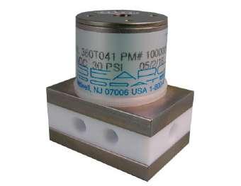
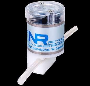
Figure 1. Typical solenoid valve
One of the many laws of physics states that energy is the quantitative property that must be transferred to an object in order to perform work on, or to heat, the object. Energy is a conserved quantity; the law of conservation of energy states that energy can be converted in form, but not created or destroyed.
In the real world, we are more likely to think of the concept of power rather than pure energy as it is more relative to the tasks we need to perform. For electro-magnetic devices, the subject of this editorial, the principle is simple:
Electricity In = Electro-Magnetic Field = Magnetic Attraction = Mechanical Movement.
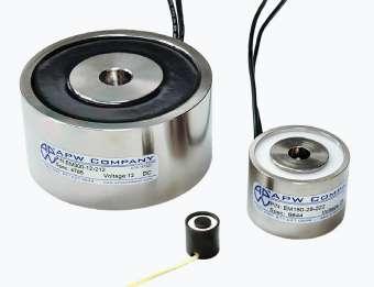
Figure 2. Sample electro-magnet
Simplistically speaking, that is all there is to it; however, each time there is a transfer from one form of power/energy to another, there will be some losses that are inherent in the device. The most wasteful phase is after the mechanical movement has been achieved and the magnetic circuit has been completed, the power to hold the device in position is considerably reduced. Assuming that the instrument’s design allows the same power to flow through the device, the excess power is liberated as heat and it is this heat build-up that should be addressed.
Wasting power may not appear to be a major consideration for mains-powered
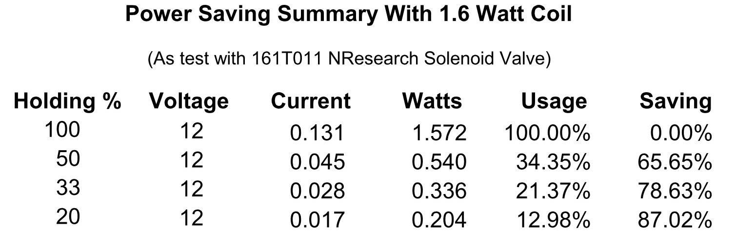
Figure 4. Sample power savings
equipment, but what if there is need for a battery-operated instrument with a long field life? Even mains-operated instruments can benefit from power reduction, savings on the cost of electronic power supplies and reduction in physical size and weight of the final instrument.
Electro-mechanical devices are designated to have specific duty ratings which will greatly affect their potential to generate excessive heat, and particular care needs to be taken when selecting such devices to match the application in hand. A 100%
duty coil may happily remain energised for 24/7 but it will still get warm, possibly higher than the actual application can comfortably tolerate. Whereas, a 50% duty coil when energised then held at a reduced power setting will remain cool even at 24/7, and will more than likely be physically smaller and more cost-effective too.
Mitigation of the impact of heat from electro-mechanical devices is a two-fold problem, as not only can the heat be detrimental to chemists and other users of analytical instruments, it is also a design conundrum for the designers of the devices themselves.
There are a multitude of solenoid valves used in laboratory instruments and process systems. What they have in common is that heat can be detrimental to their performance and reliability, and can directly affect the materials of construction and promote premature failure.
Most solenoid valves for analytical and scientific use are designed to be small and inert and have low internal volumes. However, many do not have 100% duty rated coils – something that is often overlooked when the valves are being used and, as a result, the performance can be compromised. Because of this, applications that may well have worked well using manual valves during the development phase can have unwelcome results when solenoid valves are substituted for their counterparts and energised for long periods. Vaporising of media and formation of crystalline structures within valves is a particular problem.
The duty rating is also important when it comes down to basic physics, as noted earlier in this article: put power in and heat will come out somewhere along the line if nothing is done to control the device efficiently.
The coil in the solenoid is designed to develop sufficient force to operate the valve at a specified voltage by attracting the armature and completing the magnetic circuit. Once the armature has moved and completes the magnet circuit between itself and the core, the power required to keep the valve energised is reduced. However, the coil is still drawing the same current as it did to initially energise as the resistance of the coil remains the same and the excess power is dissipated as heat. Once again, physics is the reason for this; the attraction of the magnetic field is calculated as the square
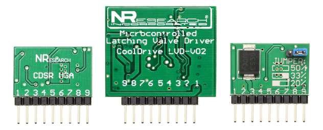
Figure 5. Typical driver implementations
of the distance the armature must move, double the distance, quadruple the power requirement. Therefore, as the air gap in the magnetic field of the device closes, the power requirement reduces.
What can be done to reduce the heat and power requirements of solenoid valves? There are a number of options available to the system designer, the two most common being latching valves and the use of strikeand-hold drivers.
Latching valves are devices that are bistable, only being energised to change state but then held in position by mechanical means. More often than not, this is achieved with at least one permanent magnet or a mechanical latch. The advantages include excellent power-saving, as no power is required once the desired state is achieved and they maintain position even when there is no power available at all. Their holding is limited only by the magnetic force or latch designed into the device, and they are ideal for use on battery-operated portable equipment.
The disadvantages of latching valves are the facts that they are more expensive than standard valves, in most cases physically larger than standard products, and always need a specific driver to operate them. Care must also be taken when designing systems and instruments using bi-stable latching valves to be mindful of the fact that a recovery sequence must be programmed in to the control software to ensure the valve is in a known position when re-starting the system, health and safety always being a priority.
With regard to strike-and-hold drivers, this refers to energising valves using an electronic driver to first apply a pull-in voltage and then a lower voltage to hold the valve in the energised state. This type of operating system is in general use, but the methods used to attain the function vary widely. One of the advantages of this approach is that it is possible to power boost the strike voltage by over driving a coil for a short period of time before reducing the voltage to hold the device. Three of the methods generally used are voltage control, current control and pulse width modulation (PWM).
The advantages of strike-and-hold drivers include the fact that they can use standard valves at no extra cost, and they can also work on pinch valves.
Power-saving can typically be 68 per cent (but will vary between manufacturers) and they provide improved battery life when used on portable equipment. There are only two main disadvantages associated with strike-and-hold drivers: they need a driver for switching and some pinch valves need increased holding currents as they need to maintain compression, so less power savings are attained.
Voltage-controlled drivers, as the name suggests, work on the principle that after initially energising the device, the voltage is dropped to the holding voltage. This is a simple approach, but in most cases a resistor is used to drop the voltage and in doing so the total heat emissions are not always reduced, just transferred to the resistor and in doing so, there is minimal power-saving.
Current controlled drivers operate similarly to the voltage-controlled circuits, but reduce the current instead.
Far more efficient and cost-effective are pulse width modulation drivers as there is virtually no resistance in the path of the current flow and as such, little or no heat is generated within the driver circuitry. By switching the power on and off at a set frequency with variable duty cycles, it is possible to generate precise holding states. This method of voltage/current generation is variable from 0–100% duty within a simple circuit and with readily available components.
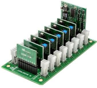
Figure 6. Modular drivers Figure 7. Integrated driver and connector
Implementation of drivers for energising solenoid valves and electro-magnets is a matter of manufacturer’s preference, and can be anything from integral circuits on the main mother boards or as single drivers, modular, multiple assemblies, integrated within or mounted on the device or incorporated in an electrical connector. Some drivers will incorporate visual aids such as LEDs indicating they are energised or a fault condition. There is such a variety available, the choice is whatever fulfils your specific requirements best.
Whatever method is ultimately chosen to mitigate heat-rise and promote costeffective and efficient control of your electro-magnetic devices, rest assured just switching them on and off is not the best option.
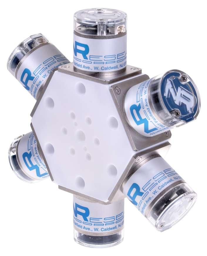
Figure 8. DIN connector driver

Gary Stevens
Gary Stevens is Managing Director of NResearch UK Limited and has over 40 years of experience in the fluidic valve control market. Specialising in the application of pinch valves, solenoid operated isolation valves and precision metering pumps for scientific and analytical instruments. In addition to the supply of proprietary products, Mr. Stevens also designs bespoke components for embedded manifold assemblies and devices for electronically interfacing and driving solenoid valves. Visit www.nresearch. com for more information.
Email: gstevens@nresearch.com


