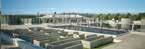
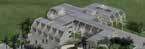
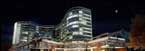
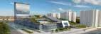
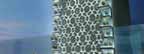
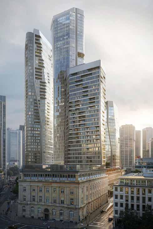
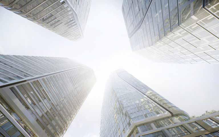
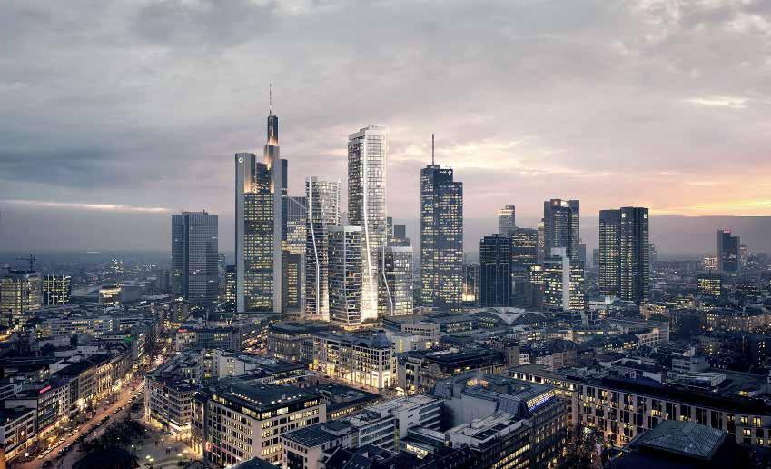
The area addresses a development blockade in the city center that had persisted for more than seven decades: Roßmarkt and Junghofstrasse, reconnecting the city with the banking district structurally. The four skyscrapers rest on a multi-story podium that forms the core of the new district. Here, access routes to the city and surrounding neighborhoods flow, including inviting passages with retail and gastronomic offerings such as a food hall. Between the facades, city squares with unique atmospheres are created, and a spacious roof terrace on the podium provides a memorable experience.
The tallest tower (T1) of the quartet reaches a height of 233 meters. Similar to Tower 4, office spaces will be distributed across its 55 floors. Tower T2, at 173 meters, will be among the tallest residential high-rise buildings in Germany, while the second residential tower (T3) also stands impressively at 120 meters. The office tower (T4), standing 100 meters tall, has 25 floors. In addition to a hotel, serviced apartments, and office spaces, the development will include approximately 600 apartments with loggias and direct visual connections to the weather and clouds.
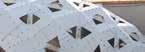
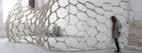
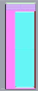
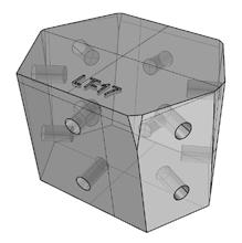
My role in this project focused on creating 3D files of facade panels in LOD 400 standards. Although it was possible to model these panels manually in Rhinoceros software, using algorithmic tools like Grasshopper offered significant benefits, such as reducing modeling time, increasing precision, and simplifying edits.
There are approximately 72,000 possible panel variations based on the parameters in the facade design. Each panel contains between 350 and 550 elements depending on these parameters, making manual modeling and verification challenging. The Grasshopper code we developed can model each panel in less than a minute, including all detailed features.
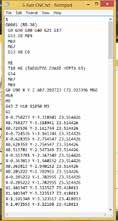
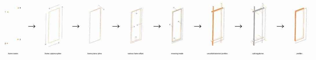
The final step was to provide the manufacturing team with shop drawings for each part. We automated most of this process using an algorithm. The user would access the 3D model, specify the part’s orientation, and the algorithm would generate a shop drawing that includes an isometric image, top view, and front view with dimensions. A few adjustments might be required by the user before submitting the documents to the client.
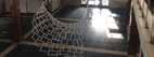
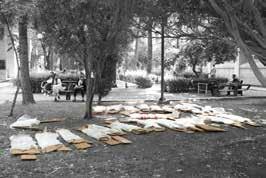
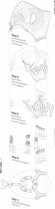
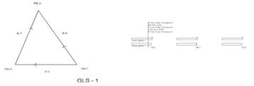
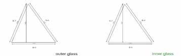
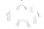
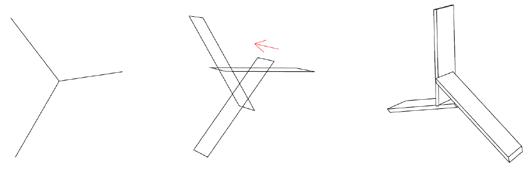
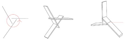
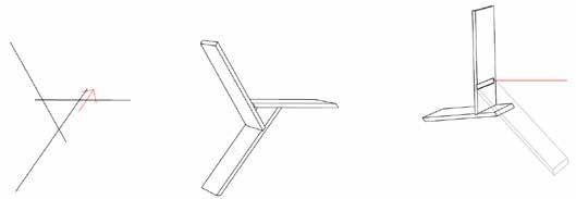
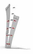
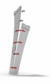
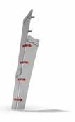
Assembely Process
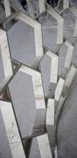
Step 0: offloading the elements and sorting them
Step 1: assembling the base plate segments
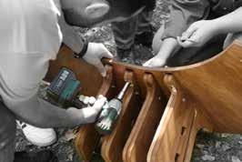
Step 2: connecting the supports to the base plate
Step 3: assembling the elements related to the outer supports
Step 4: assembling the elements related to inner supports
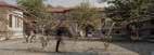
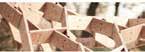
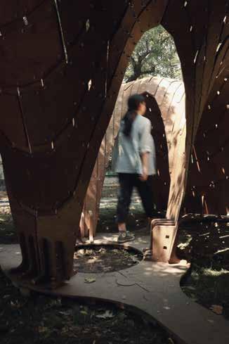
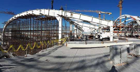
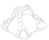
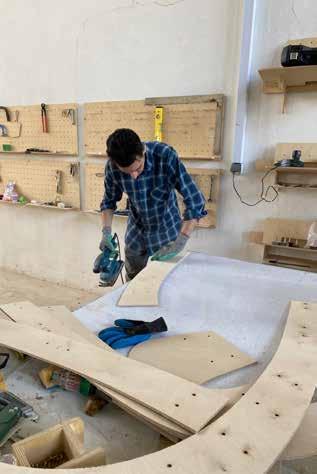
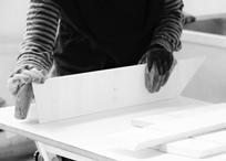
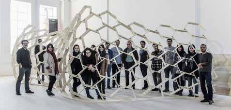
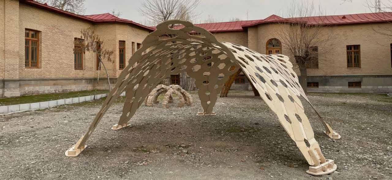
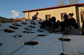
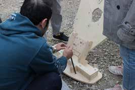
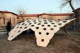
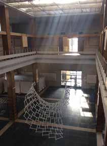
The DigiPy Workshop, held during the summer of 2023, was a hybrid digital fabrication workshop organized by digitalFUTURES in collaboration with Digital Craft House and Dahi Studio. This workshop aimed to introduce participants (48 students) to computational design and digital fabrication, allowing them to construct a pavilion at a 1:1 scale.
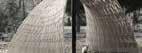
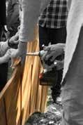
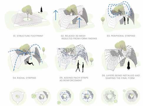
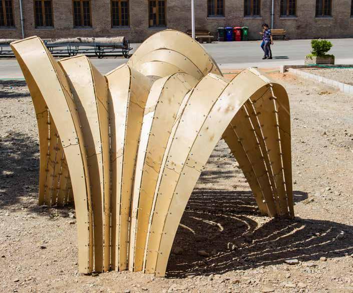
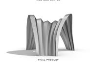
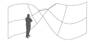
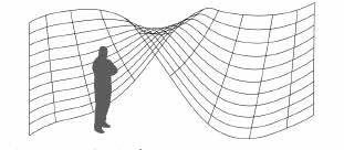
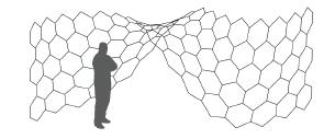
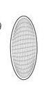
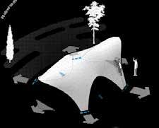
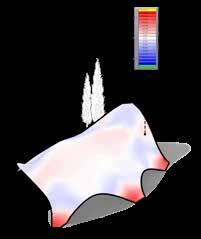
The final project centers on utilizing bending to induce elastic deformations within the structural framework. Through the active-bend methodology, the workshop introduced an innovative approach to conventional flat-based manufacturing processes. The primary objective of this fabrication approach was to achieve a bending-active structure, as exemplified by the double-curved surface of the Cavilion, which emerged from the elastic deformation of initially planar components.
The choice to employ the active-bend methodology as the primary approach was based on its inherent simplicity in manufacturing planar components, which are subsequently shaped into curved elements during the assembly process. Additional benefits include ease of transportation and assembly, as well as enhanced structural performance and adaptability. Moreover, by applying elastic deformation, the approach enabled a cost-effective construction for the intricate architecture of the Cavilion.
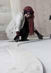
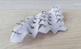
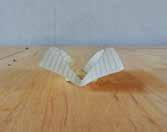
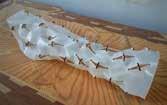
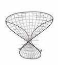
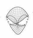
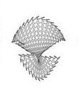
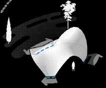
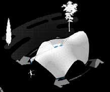
The assembly process began with the installation of the base plate and supports, facilitating the positioning and installation of the strip elements. Guided by the weave map generated from the Grasshopper model, assembly started from the supports and areas with minimal curvature, progressively advancing toward areas with higher curvature. This systematic approach ensured a smooth and efficient construction process. The fabrication of the Cavilion structure took place over three days on the campus of the University of Tehran, culminating in the pavilion’s successful physical realization.
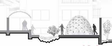
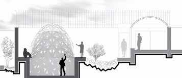
Exploded Diagram
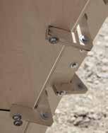
Connecting the Layers to Each Other
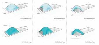
Form Development Process
FARMANIE MALL FREEFORM
Tehran, Iran | 2017 summer
Role: Concept Designer and Detail Designer
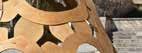
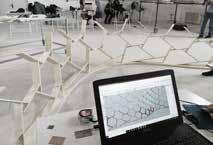
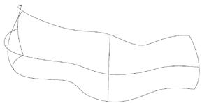
This project aimed to automate the creation of shop drawings for a freeform spatial frame system. In such structural systems, each element, joint, and glass sheet is geometrically unique. Therefore, preparing shop drawings manually for each component is a tedious and time-consuming task, often prone to human error due to the variety of shapes involved. To address this, our approach was to create a code in Grasshopper that would convert the structure’s wire mesh into a fully detailed Building Information Model (BIM). This program eliminated the need for an operator to manually create the model, generate shop drawings, and check for errors.
This solution greatly simplifies the design and construction of freeform spatial frames. Designers can now generate a basic wire mesh and instantly view a real-time, fully detailed model. Up to 2018, two freeform surfaces in Tehran were designed and built using this code, with another currently under design in Istanbul.
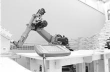
Another critical aspect of this project was the use of 5-axis CNC machines for fabricating the nodes—a type of machine rarely used by architects in Iran. To streamline the fabrication process, I developed a Grasshopper script to generate a toolpath for the CNC machine, converting the data into G-code compatible with a table-table 5-axis FANUC CNC machine.
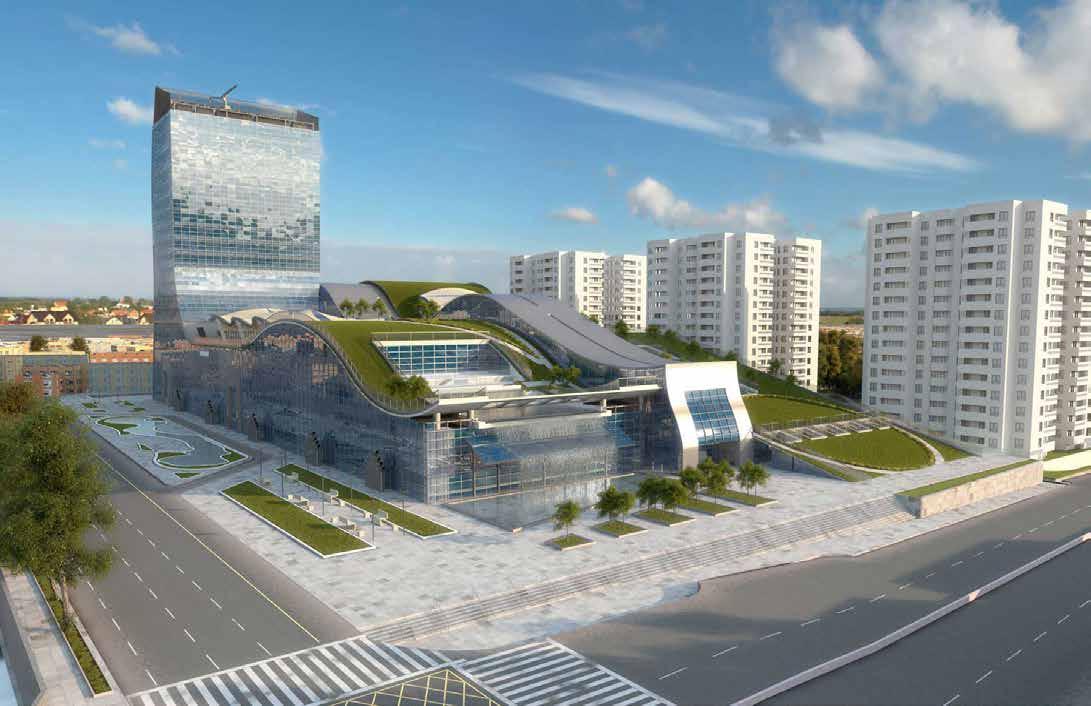
MEGAPARS
Tehran, Iran | 2016, Spring Role: Energy Consultant for facade
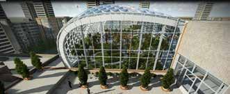
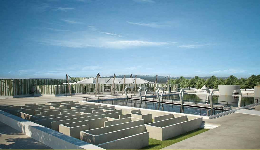
MegaPars, the first green mall in Persia, showcases a high level of sustainability across various dimensions, making it a distinguished project in the region. Nature serves as a central inspiration, evident in features like a massive, sparkling waterfall (24x11m) and the sweeping natural curves of a 1-hectare green roof covered with herbs, bushes, and trees, plus an additional 10,000 square meters of landscaped area. These elements blend architecture with nature, transforming MegaPars into a green landmark within the city.
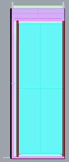
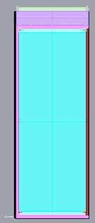
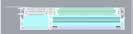
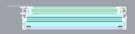
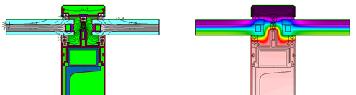
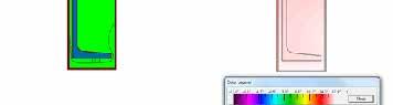
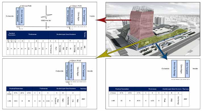
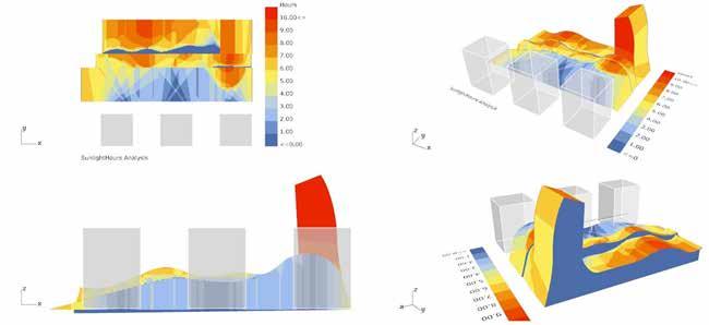
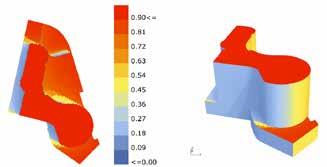
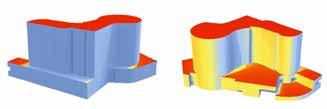
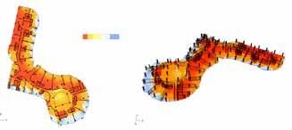
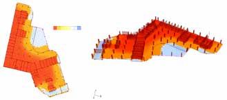
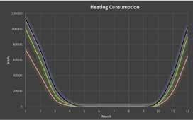
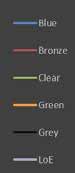
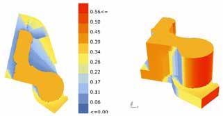
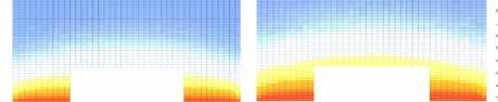
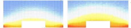
Energy efficiency is a critical priority for the project’s owners. Given the scale of the project, optimization in each element significantly impacts energy performance. I began with general analyses such as solar radiation, illuminance, energy consumption, and thermal bridging for the proposed façade system. By adjusting specific parts of our curtain wall details, I was able to reduce the façade’s heat transfer rate. This approach allowed our company to avoid changing materials, which positively impacted our financial and scheduling goals. It was the first time our company achieved such energy efficiency through detailed design adjustments rather than material changes. Additionally, I evaluated the effects of different types of glass to reduce energy consumption based on climate analysis. Last year, MegaPars received the prestigious Energy Globe World Award for its commitment to energy efficiency.
Heat Transfer Rate in Mullions
MOT TOWER
Free-form Facade Shop drawing
Baku, Azerbaijan | 2017
In cooperation with EMRE ISTIKAM Co
Role: Writing the generative code which convert the wire mesh model to full detailed BIM model
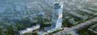
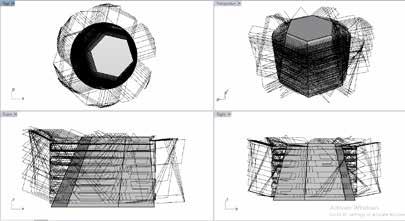
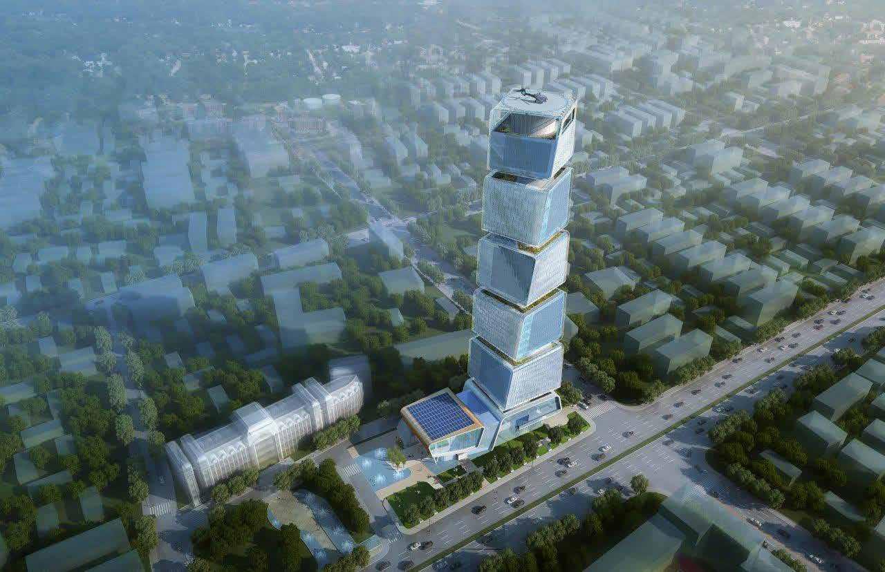
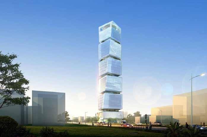
The new 170-meter-tall building consists of five twisting cubes of varying sizes positioned on podiums. Its unique geometric design, characterized by the twisting forms and innovative building services, establishes the MOT Tower as a landmark project in Azerbaijan.
The unitized curtain wall system used in this tower features non-planar glass panels that present challenges in construction. Therefore, the primary objective of this project was to identify the best planar panel that closely approximates each non-planar panel, ensuring that the overall shape of the building remains intact. Additionally, it was essential to devise an efficient method for generating shop drawings for these panels. Due to the gradual, subtle variation in each panel, the drawing process could be extremely challenging for any draftsperson. To address this, we developed code in Grasshopper to automate the drawing process, making it both fast and error-free.
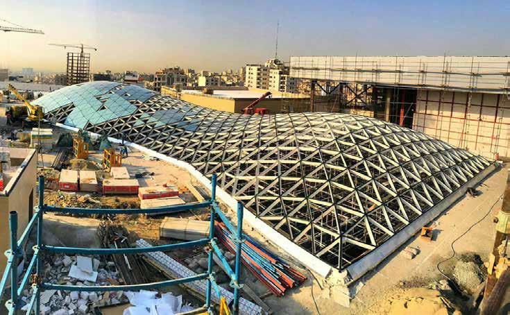
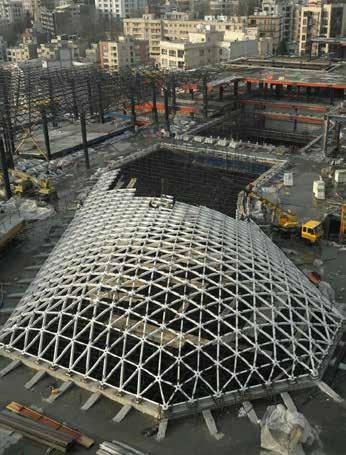
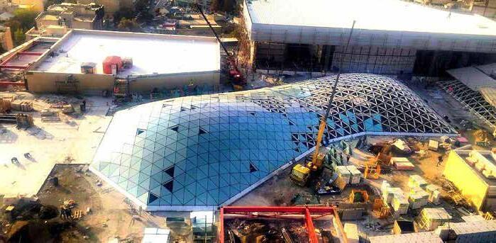
MASHHAD MALL FREEFORM
Mashhad, Iran | 2019 Fall
Role: Form optimizer and Structural pre-optimizer of the freeform
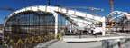
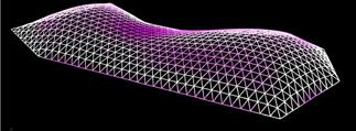
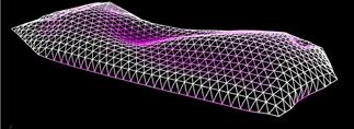
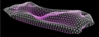
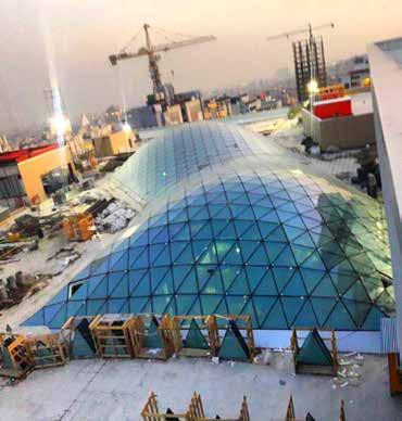
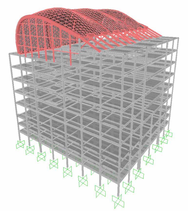
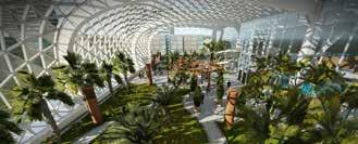
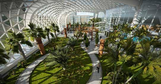
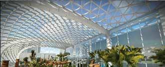
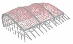
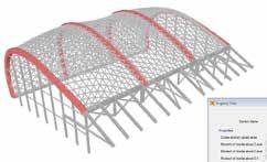
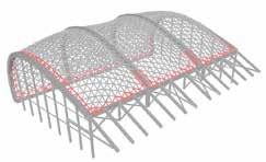
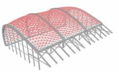
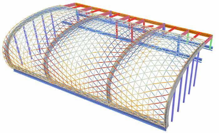
This project involves architectural form-finding and structural pre-optimization of the freeform skylight in the tropical garden of Mashhad Mall. Spanning 22 meters in width and 52 meters in length, it is the largest freeform structure in Iran. For form-finding of the skylight shape, the Karamba 3D plug-in was used for parametric modeling, integrating both architectural and structural optimization. To achieve optimal structural behavior, various profile sections and beam patterns were analyzed.
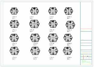
Due to the unique shape of each beam, node, and glass panel, detailed design and fabrication must be executed through a parametric process. For this purpose, creating a flawless and comprehensive model in Grasshopper was essential, requiring advanced geometric knowledge.
Another crucial aspect of this project was the use of 5-axis CNC machines for node fabrication, which is uncommon for architects in Iran. To streamline the fabrication process, I developed a Grasshopper definition to create the CNC machine’s toolpath and convert the data into G-code for a table-table 5-axis FANUC CNC machine.
ROBOTISM WORKSHOP
Tehran, Iran | 2019 Fall
Role: Tutor
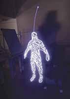
ROBOTISM was a ten-day workshop held in December 2019 at the University of Tehran, focusing specifically on computational design and robotic fabrication. The workshop included 45 undergraduate and graduate architecture students, who were divided into groups of 5 to 6 to practice working with the KUKA KR6 robot, equipped with a KRC2 controller.
Process: At the beginning of the workshop, students were introduced to KRL syntax and the basics of generating G-codes. In the first part of the workshop, each group completed two series of foundational exercises to understand path concepts in robot simulation. For the first exercise, they used Grasshopper 3D to draw continuous curves with specific patterns and define the robot’s motion path. After generating the G-codes, they practiced light painting by attaching a simple LED tool to the robot’s head, enabling it to follow the specified paths and “paint” the pattern with light. In the next exercise, each group was tasked with designing a structure using wooden pieces of specified sizes and quantities and assembling it with the Pick and Place technique. The challenge was to ensure the structure’s stability without using screws or glue.
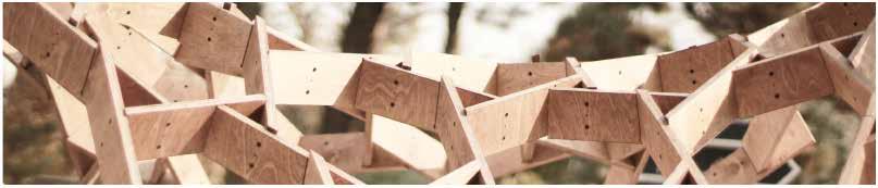
Final Product: After completing the introductory tasks and becoming familiar with practical challenges— such as properly defining planes to prevent collisions with the robot arm, installing a pneumatic gripper, and setting up an air pump—students began designing a 1:1 scale pavilion. A major design restriction was the limited material: 40 square meters of 18-mm plywood. All proposals were reviewed by a jury, and one design was ultimately selected as the final project.
Cells
Computer-Aided Design & Fabrication
Tehran & Karaj, Iran | 2022 Winter Role: Instructor
This project presents the outcome of a ComputerAided Design and Fabrication elective course offered at the University of Tehran, Iran, in the winter of 2022. The course was designed for both bachelor’s and master’s students in Architecture and spanned sixteen weeks. During the first six weeks, students were introduced to Rhinoceros software and the Grasshopper plug-in. The following six weeks were dedicated to the conceptualization and development of a pavilion design. At the end of this stage, students voted for the best design, which was then selected as their final project. The last four weeks were allocated to redesign, detailed design, and 1:1 scale mockup tests.
The chosen pavilion design process involved using random points as the initial input to create Voronoi cells. The Voronoi edges were then offset to create an integrated planar strip. This strip was transformed into a 3D curved mesh using the Kangaroo plugin, simulating a catenary chain. In the following steps, longitudinal and transverse strips were extracted from the curved mesh. Reinforced strips were created by varying the offset of the main mesh to strengthen the structure against lateral and gravitational loads. Finally, a curved base was used to connect all the elements in their correct positions.
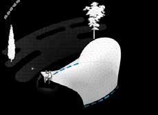
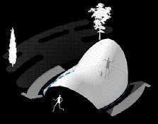
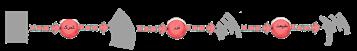
Generative diagrams, shows how the final shape is result of a path and a section. ACADEMIC AND PROFESSIONAL
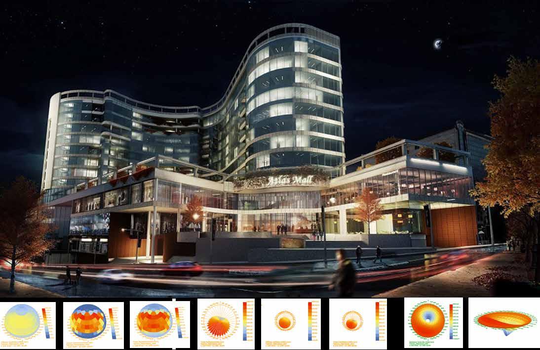
ATLAS MALL CENTER
Tehran, Iran | 2015 summer
Role: Energy Consultant for facade
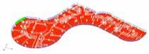
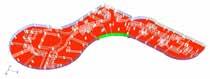
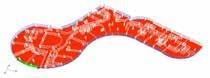
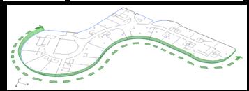
Atlas Mall Center is located in the northern part of Tehran, Iran. This project involves a façade covering a nineteen-floor commercial complex, consisting of various materials such as double-layer glass, ceramics, aluminum panels, and vertical gardens. To achieve optimal material properties for this building, I focused on energy consumption and illuminance analyses. During these analyses, I found that the location of the vertical garden has a significant impact on both heating and cooling consumption. By adjusting the vertical garden’s position by only 12 meters, energy consumption was reduced by around 10%.
To determine the optimal location and minimize energy consumption, I used a Genetic Algorithm along with Grasshopper, DIVA, Honeybee, and Rhinoceros software. Additionally, I calculated the impact of different glass types and colors on energy costs throughout the project’s life cycle.
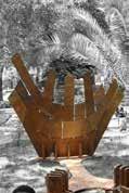
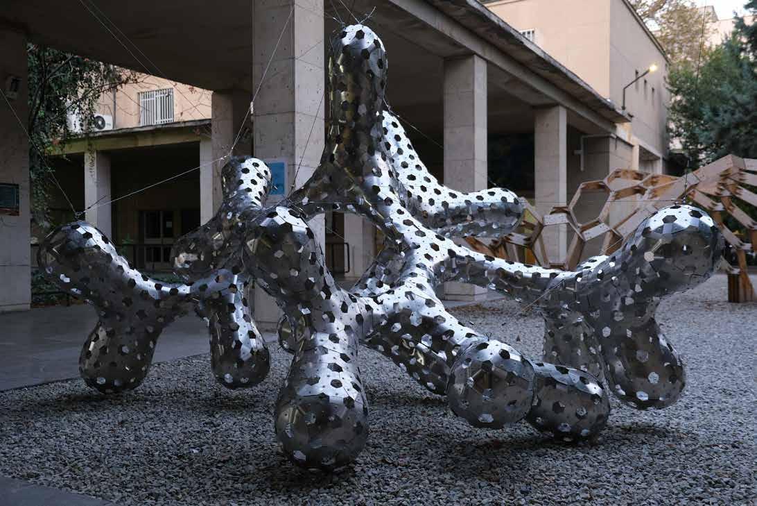
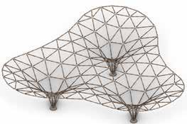
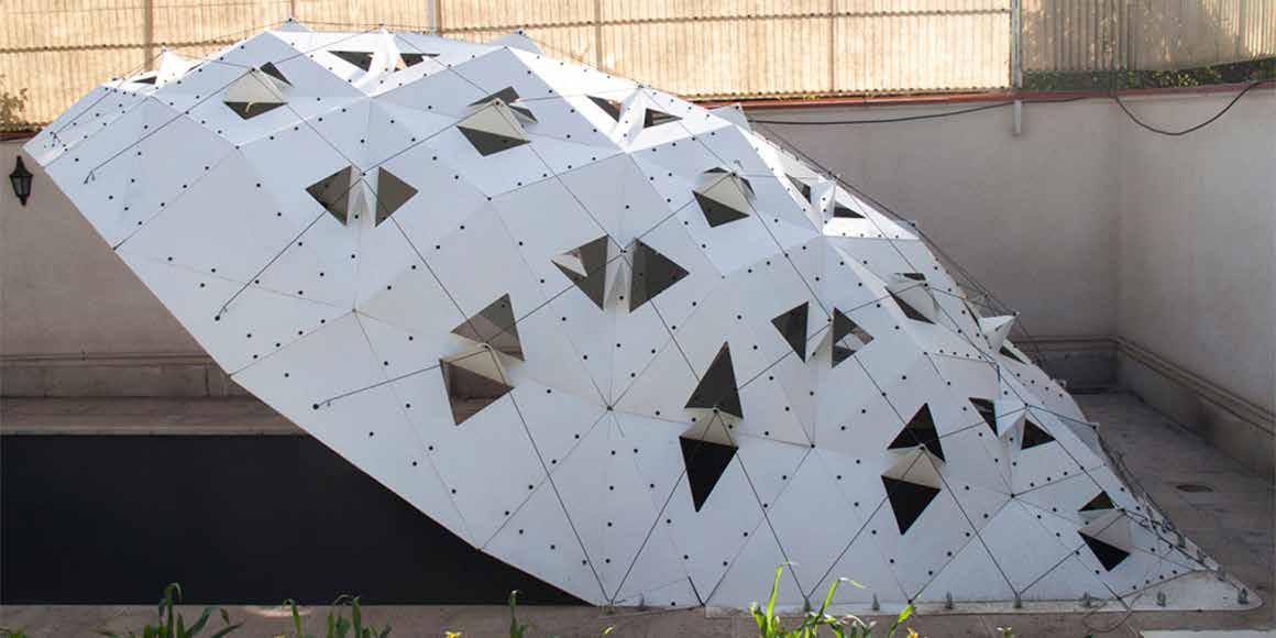
Hydra Structure
University of Tehran, Iran | 2023 Spring Role: Instructor
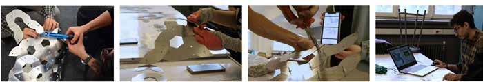
The “Computer-Aided Design and Fabrication” course, held at Tehran University, aimed to introduce students to the fundamentals of computational design and digital fabrication. In this course, students designed projects based on the theoretical knowledge gained throughout the semester. One of these projects was selected by the students for fabrication.
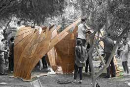
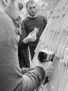
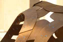
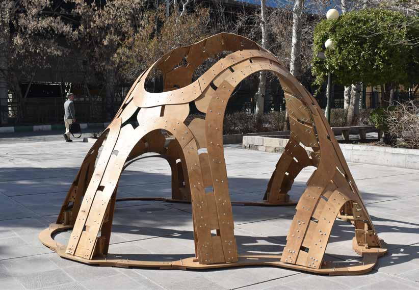
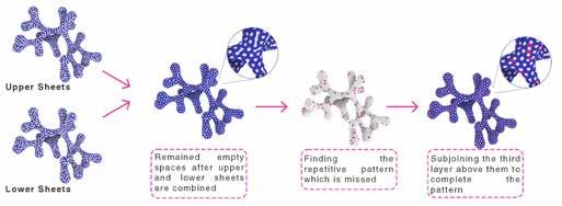
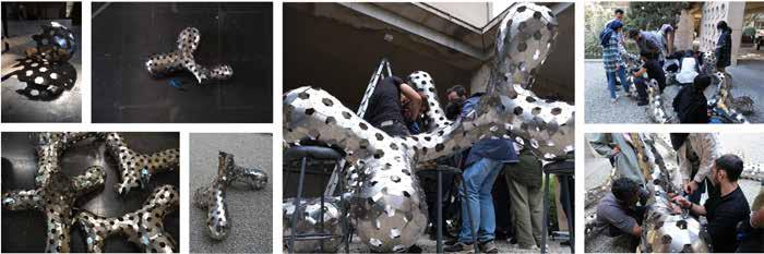
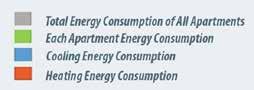
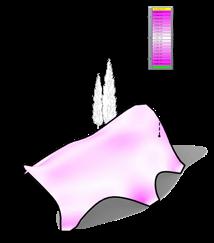
The final project was formed based on the bending-active concept. To achieve the desired stress tolerance within the structure, spring steel sheets (0.3 mm thickness) were used for their resilience within the bending range. Each uniquely shaped slab overlapped with others and contributed to the final form, assembled in three layers.
This course enabled students to explore parametric modeling, algorithmic thinking, teamwork, experimental fabrication, and the challenges of constructing at a real-life scale.
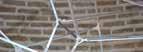
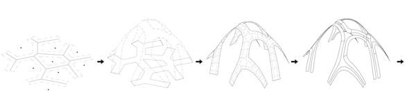
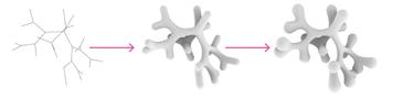
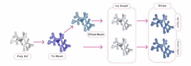
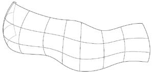
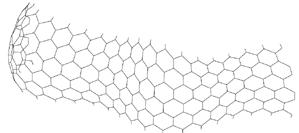
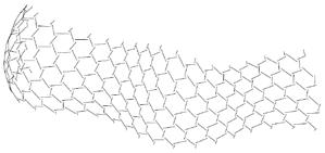
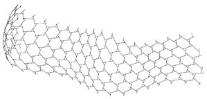
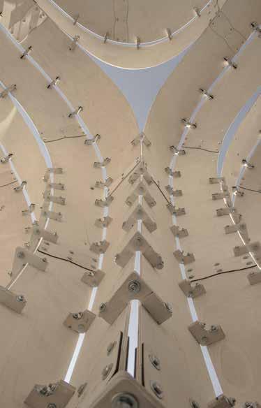
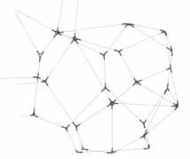
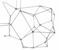
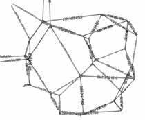
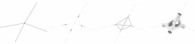
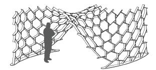
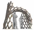
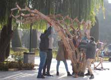
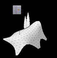
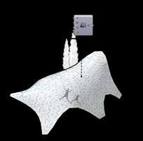
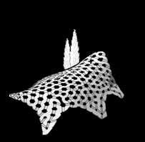
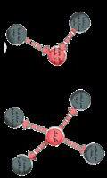
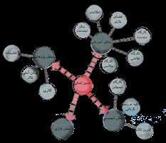
Inspired by Marc Fornes’ designs, the form initially began as a three-dimensional net composed of linear components. This net was transformed into a ramified mass using the multi-pipe technique, with free ends of the branches curved to refine the structure.
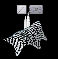
To break down the polysurface of the form into ribbons, the Ivy plugin was used to create a graph on the triangulated mesh. The ribbons were aligned through two perpendicular rows to shape the form. However, the ribbons were not woven together but instead stacked on top of each other and secured with bolts and nuts. Two layers—upper and lower—were created. To ensure perpendicular alignment, the lower layer graph was based on the upper layer graph, meaning the weight of the upper layer graph was used to generate the lower layer graph.
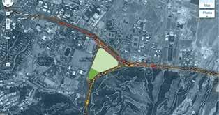
BAHARAN RESIDENTIAL COMPLEX
Tehran, Iran | 2014 Winter
M.A. Final Project
Role: Designer
19.5 out of 20
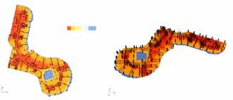
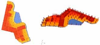
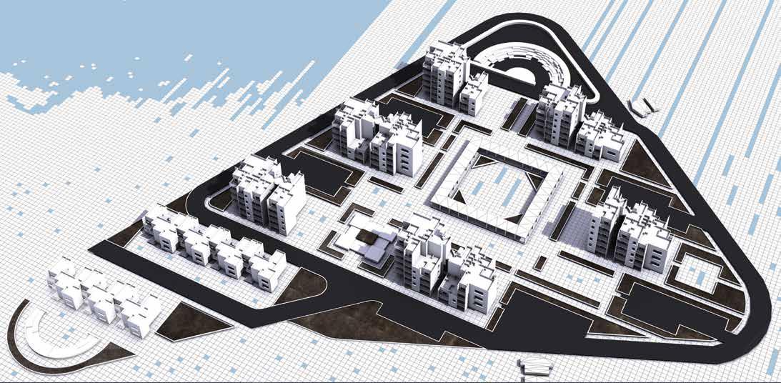
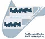
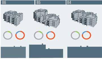
The research presented in this project is divided into three main sections: 1) designing optimal plans for a two-story villa unit, 2) designing an optimal site plan for villa units, and 3) designing the optimal form of 12-story apartment buildings based on a fixed plan and specific locations within the site plan.
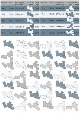
Villa Units: Given the variability of computer-generated plans, the area of each floor of the villa units ranges from 140 to 160 square meters, with a floor height of 3 meters. Prototype plans were developed to initiate the optimization process, and some computer-generated forms are shown in the figure. The computer can adjust parametric angles of elements to create new plans. Due to the movement constraints at 90-degree angles, there are 729,000 possible configurations for the initial plan. Table 1 displays the results for the top 10 configurations, showing energy consumption per square meter, area, and perimeter. The optimization process reduces energy consumption by 21% compared to the original plan.
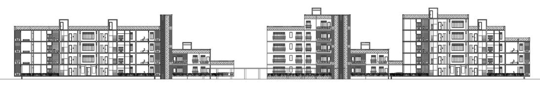
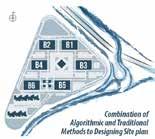
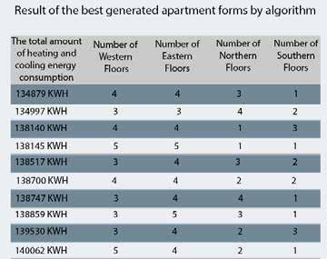
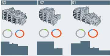
Apartment Units: The apartment buildings consist of four units per floor, with unit dimensions as follows: 158 m² for Unit A, 55 m² for Unit B, 55 m² for Unit C, and 167 m² for Unit D. The computer generates different forms based on these fixed plans and can vary the number of floors used from each apartment building plan to produce additional configurations. The location of the apartment buildings within the site is predetermined and remains fixed. Table 2 presents an analysis of the top 10 results, including key parameters. The optimization process reduces energy consumption by 26% compared to the initial configuration.
For all results and further progress, please refer to the video links below: https://www.youtube.com/watch?v=f0QkDzTHngA
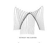
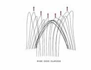
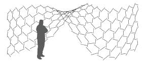
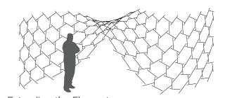
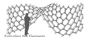
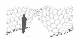
Main Curves
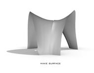
Generating the surface
Pattern drawing
Rotating the elements
Extending the elements
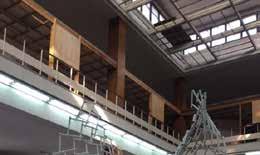
Nexorade II Workshop
Tehran & Karaj, Iran | 2018 Winter Role: Tutor
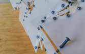
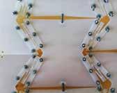
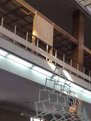
Free-form Space Structure Workshops are conducted to research and practice in the areas of freeform structures and computer-integrated construction and design methods. Each training program focuses on a specific method of constructing free-form structures. In this particular workshop, participants explored and constructed a Nexorade structure. Initially, students worked to understand the logic of the Nexorade system. They then developed their designs using digital fabrication tools, ultimately producing them at full scale. All parts of this structure were made from 12mm thick plywood and cut using digital cutting machines, with the components connected by nails.
Process: The workshop began with a two-part phase: training and hands-on experience. In the training portion, students were introduced to Grasshopper software as a digital design tool and to digital fabrication tools to explore their design capabilities. They practiced building a simple structure with wooden sticks. In the next step, students engaged in an integrated computational design and fabrication process. They designed a Nexorade structure, adaptable to 3mm thick plywood and laser cutting systems, incorporating a basic joint detail and developing a Grasshopper code to generate models and shop drawings. In the final phase, one of the students’ designs was selected for the full-scale model. This proposal featured a partition to separate two sections of DCHouse. Here, students worked to optimize joint details, adhering to material restrictions (12mm thick plywood) and limiting fabrication techniques to CNC milling.
Final Product: After finalizing the model, the team generated a G-code for the CNC milling machine to cut the components at the specified angles. The structure’s footprint served as the base plate. Students then assembled the pieces, placing each element one by one until completion. During this process, a designated person directed the placement of each component. The entire installation process took approximately 15 hours.
Numbering
Nailing line
Footprint of the other element
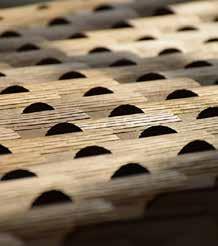
In order to ease in assembling, footprint of each element engraved on the other by CNC milling machine.
Bending Active Surface Workshop
Tehran & Karaj, Iran | 2019 Summer Role: Tutor
The workshop, held in September 2019, was organized in collaboration with the University of Art and the University of Tehran by Digital Craft House at the University of Art, the Centre of Excellence in Architectural Technology, and the Association of Architectural Technology at the University of Tehran. The workshop aimed to provide students with an integrated digital design experience and familiarity with digital fabrication tools and facilities. Our ultimate goal was to produce two pavilions at the two universities. Both pavilions were constructed using plywood sheets and a surfaceactive structural technique. The testing, manufacturing, and assembly of all pavilion components were digitally managed.
Process: In the preliminary phase, various fabrication methods and materials were tested to assess their suitability for elastic deformation and compatibility with digital cutting machines. As a result, cardboard and high-impact polystyrene were selected for prototyping, and plywood with varying thicknesses was chosen for the final construction.
The first phase of the workshop had two components: training and practical experience. In the training segment, students were introduced to Grasshopper software as a digital design tool, along with digital fabrication methods to maximize their design potential. In the hands-on segment, students were tasked with bending sheets to form modules or components of active bending structures. Through this exercise, students successfully designed seven prototypes.
In the subsequent phase, three structural systems were selected as main options, with students divided into three groups to study and develop these systems further.
The outcome of this phase was prototypes representing one-fifth of the total structure, allowing each group to experience the process of producing a pavilion prototype using digital tools and the same level of detail as the final design. In the final step, students voted to select two designs to be built at full scale. The construction drawings were entirely generated through code in Grasshopper software, and all components were produced via CNC milling and laser cutting.
1 - WIRE MESH
2 - JOINT MODELING
3 - ELEMENT MODELING
4 - TAGGING
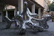
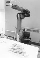
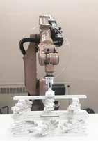
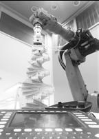
PRINTED STRUCTURE WORKSHOP
Tehran, Iran | 2022 Winter
Role: Tutor
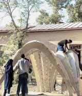
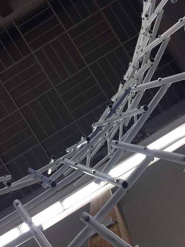
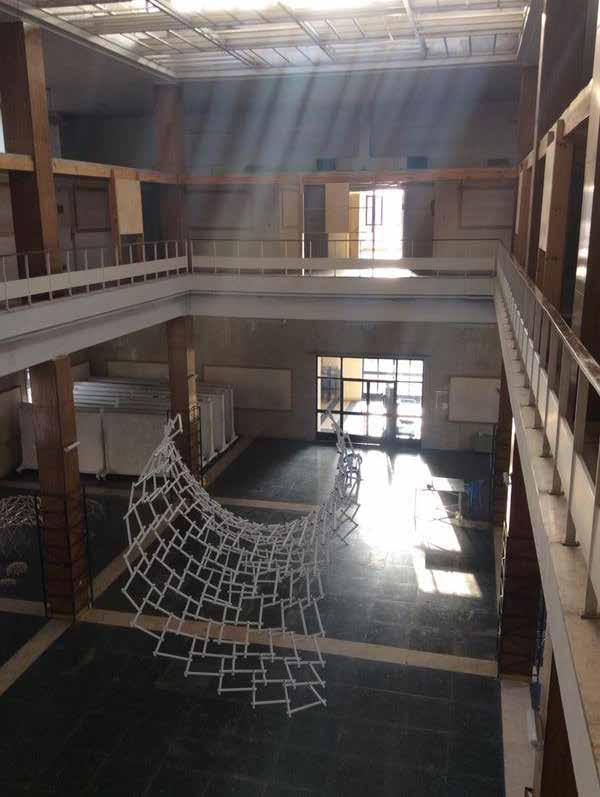
This workshop aimed to develop a lattice space frame system using 3D printing technology. Held in the winter of 2022 at the University of Art, Bagh-Melli campus, it resulted in a spatial structure with 3D-printed joints and steel bar elements.
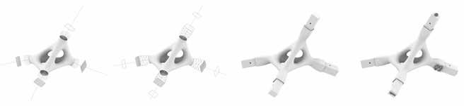
The workshop focused on two main topics: 3D printing technology and the computational design and fabrication of a freeform, non-standard spatial structure. To help participants understand and practice 3D printing, the workshop began with the fabrication of a simple object. Next, students designed and fabricated different types of joints. We then developed a BIM tool to convert a wire mesh into an LOD400 BIM model and generate fabrication data. Finally, participants fabricated the elements and assembled the structure. The workshop included seven phases:
Chapter One: The New Fabrication Paradigm
Phase One: Introduction to digital fabrication and 3D printing
Phase Two: Practicing 3D printing, understanding materials and techniques
Chapter Two: Design
Phase Three: Joint design and prototyping
Phase Four: Form design, selecting the optimal form and joint system
Chapter Three: Final Product
Phase Five: BIM modeling
Phase Six: Fabrication
Phase Seven: Assembly
On the first day, tutors introduced several topics, including digital fabrication, types of 3D printing and their applications, 3D modeling, and generating fabrication data.
To better understand 3D printing technology and its functionality, students started by designing and fabricating simple objects. Through this exercise, they learned about suitable designs for 3D printing and its limitations.
In the third phase, each group designed and developed a joint system to connect the structural elements, applying what they had learned in the introductory phases. They then fabricated these prototypes and selected the best alternative based on criteria like aesthetics and strength.
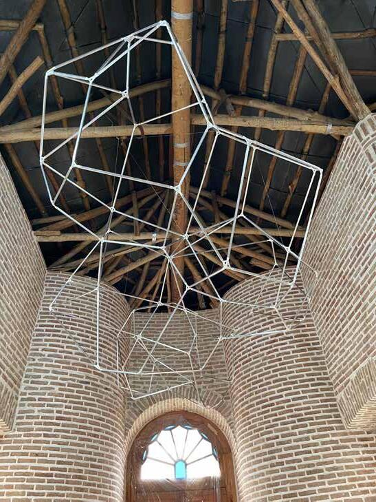
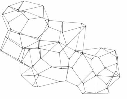
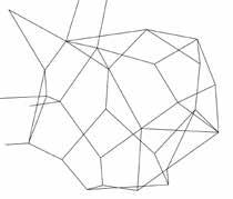
Participants generated various wire mesh forms as options for the final product of the workshop, a full-scale structure. Several designs were developed and evaluated based on their compatibility with the selected joint system. Ultimately, the researchers chose a cellular 3D Voronoi form as the optimal structure.
Since a model containing all elements, joints, bolts, and precise information was required for fabrication—a challenging task for freeform designs—we developed a computational tool that could convert the wire mesh into the final model immediately and automatically.
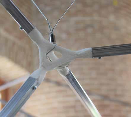
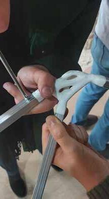
The joints, the most complex part of the structure, were fabricated using multiple 3D printers over five days. As the only variable property of the elements was their length, steel bars were cut to varying lengths from long metal profiles.
Finally, the structure was assembled by the students in a single day and was then suspended from the ceiling of the hall at the University of Art.
MAIN CURVES PATERN DRAWING GENERATING THE SURFACE ROTATING THE ELEMENTS
EXTENDING THE ELEMENTS EXTRUDING THE ELEMENTS ADDING BASE ELEMENTS COMPLETE FORM
ACADEMIC AND PROFESSIONAL
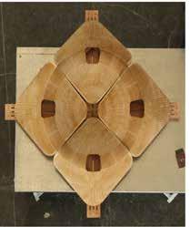
1. ELEMENTS BOUNDING BOX 2. CUT THE TOP SIDE SLOPES
3. DRILING THE CONNECTION HOLES 4. MILLING THE BACK SIDE
5. CUTTING
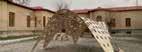
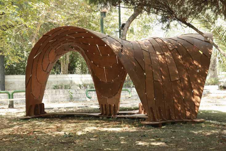
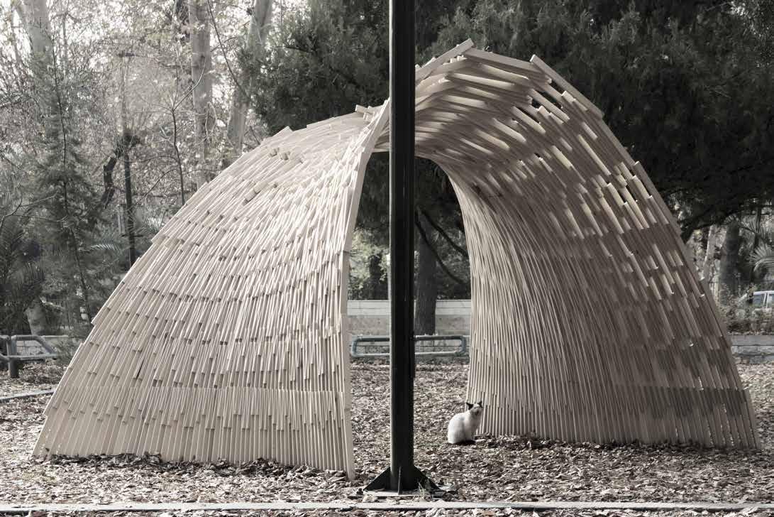
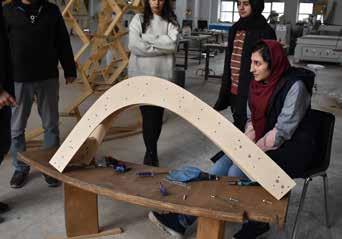
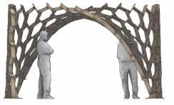
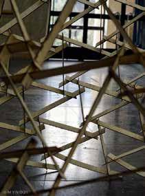
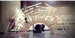
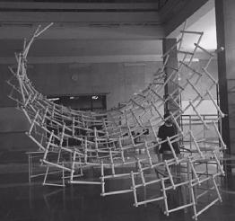
Integrity Tehran international sculpture
fair
Tehran, Iran | 2020 Winter
Role: Designer and Fabricator
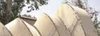
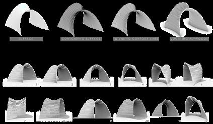
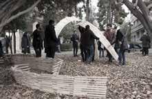
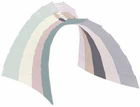
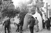
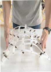
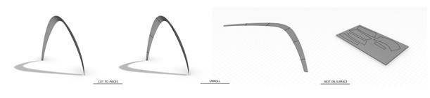
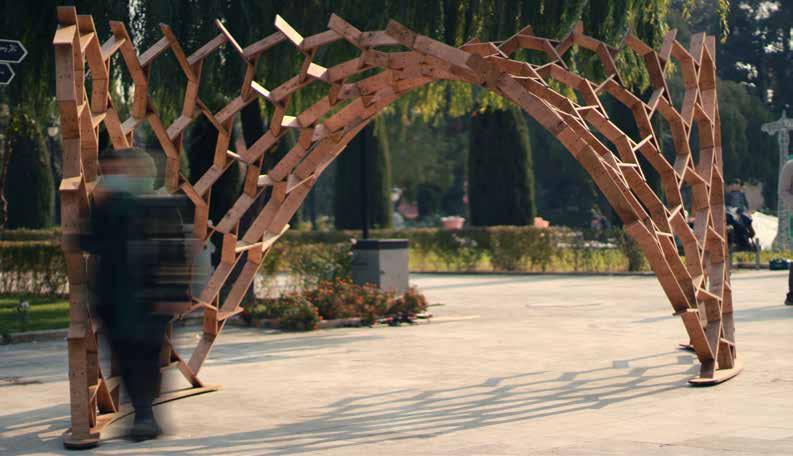
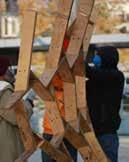
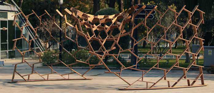
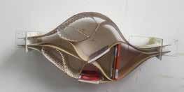
The structure was designed and fabricated in collaboration with the University of Art and Dahi Group, organized by the Digital Craft House at the University of Art in December 2020 for “The 8th Tehran National Sculpture Biennial.” This pavilion was constructed with plywood sheets using a Nexorade structural technique. Final tests and manufacturing of all pieces for this installation were digitally produced.
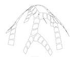
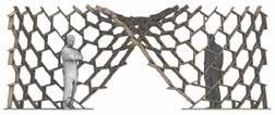
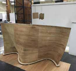
This pavilion is a strip that rises from the ground, forming an arch with a twist. This twist creates a double curvature, allowing the structure to be executed as a single layer with increased strength.
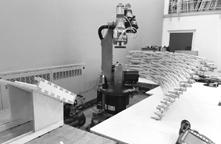
After selecting the best design alternative, the final model was prepared. The team then created G-code for the CNC milling machine to cut the parts at the designated angles. The structure’s footprint served as the base plate, and elements were placed sequentially until the structure was complete.
Three features were added to the final model:
Numbering
Footprint marks for other elements
Screw holes
Each element was screwed to the adjacent one. Holes were designed and cut by the CNC to indicate the screw positions.
To facilitate assembly, each element’s footprint was engraved onto the adjoining elements by the CNC milling machine.
During the assembly process, one person guided the team, indicating the correct placement of each element.
Uique Elements
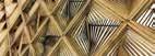
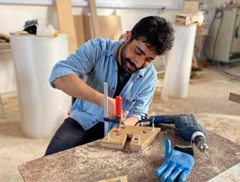
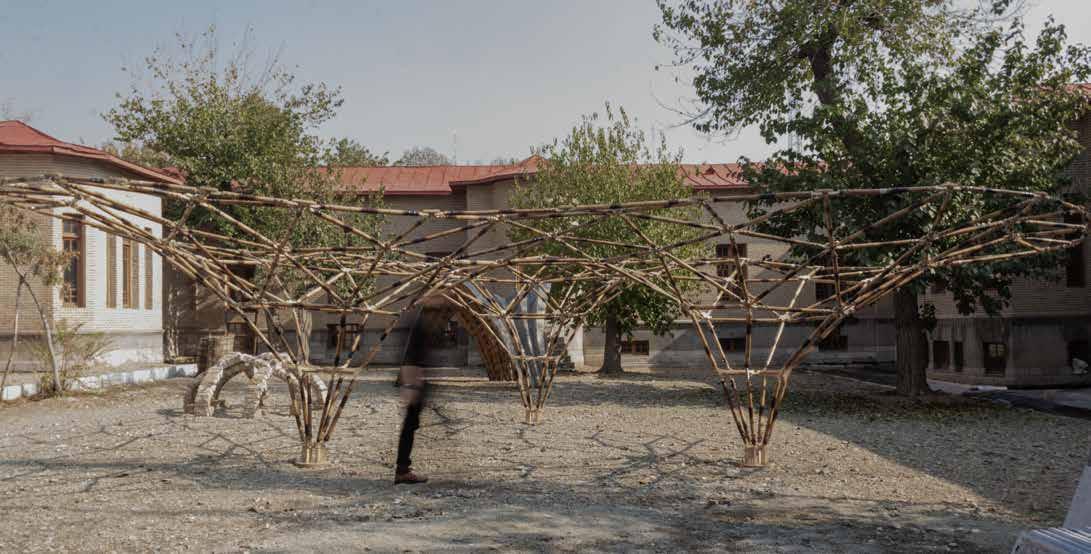
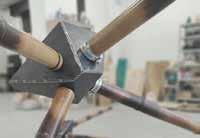
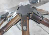
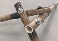
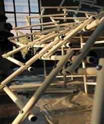
BAMBOO-BAM
Tehran, Iran | 2021 Summer
Role: Tutor
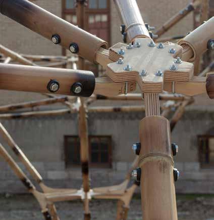
During the workshop, five major research areas were covered: material studies, sustainability, computational design, form-finding, structural design, and digital fabrication.
At the same time, research into various systems for free-form grid shells was also underway. Despite inherent differences among these systems, each was considered a potential direction for our workshop. This section of the study aimed to provide sufficient information for the upcoming phase of system design.
In the form-finding section, two groups were assigned to research different form-finding methods. They presented a brief overview of the fundamentals of each method, along with examples of projects constructed using these methods. They also explored the available tools and plugins for each. A Grasshopper code for each method was prepared to be shared and readily tested by other students.
Through a series of brainstorming sessions, various systems were proposed and then narrowed down to a shortlist. Prototypes of the shortlisted systems were created, with the fabrication method for each carefully examined. An evaluation procedure based on several criteria was conducted to assess the benefits and drawbacks of each system. The final choice was selected from these four options, and we proceeded with it.
Three-axis CNC milling machines were available, capable of drilling vertically through bamboo poles. However, the poles could not be rotated due to the unidirectional drilling capability. To address this, we considered purchasing a rotary axis, though it was not affordable and might not fit our CNC bed. As a solution, we decided to design a custom rotary axis.
1. Polyhedron
2. Nexorade
4. Radial
3. Star
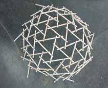
NEXORADE
WORKSHOP
Tehran, Iran | 2016 Fall
Role: Tutor
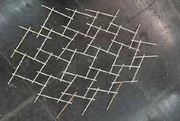
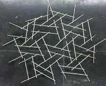
The Nexorade Workshop is another initiative by the Computational Design Committee at the University of Tehran. The aim of this workshop was to introduce digital fabrication using a CNC milling machine with a rotary axis and a laser cutter. This workshop included 34 students and 5 instructors, including myself.
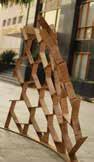
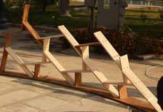
The Nexorade is a type of spatial structure that is challenging to design but relatively easy to build. This made it a suitable focus for a fabrication and computational design workshop, as it involves complex digital form-finding, providing students with valuable practice. Additionally, it is straightforward to assemble after the digital fabrication process, allowing students to construct it with limited tools and resources.
The workshop was divided into three steps: familiarity, small-scale structure, and large-scale structure. First, students worked in groups of three, arranging wooden sticks in reciprocal configurations to understand the structural logic. Following this, they used Grasshopper and Kangaroo for computational design to create small structures with a diameter of 2 meters. They used laser cutters and plywood to fabricate these models in groups of six. In the final stage, groups designed various models, after which a jury selected one design. All students collaborated to build a 5-meter-tall structure made from plastic pipes.
You can view all results and progress on the official workshop page, which is open to anyone interested: https://trello.com/b/WJVfytem/nexorade-workshop
Above: First step, Familiarity, samples created by students. Below: Product step
Below: Final results.
Form-finding Process
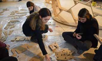
BENDING ACTIVE STRUCTURES
WORKSHOP
Tehran & Karaj, Iran | 2021 Fall
Role: Tutor
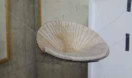
Freeform Space Structure Workshops are organized to advance research and practice in freeform structures and computer-integrated construction and design methods. The November 2021 workshop, held by Digital Craft House in collaboration with the University of Art, aimed to give students an immersive experience in digital design and fabrication tools. Our ultimate goal was to produce a pavilion at the university. The pavilion was constructed using plywood sheets and employed a surface-active structural technique. All final tests and manufacturing of pavilion components were digitally processed.
During the workshop, students explored various methods to achieve optimal solutions for form-finding and detailed design. The final form was based on large deformation logic using the Karamba 3D plugin, while IVY generated the shapes of the elements. Mesh graphs were used to determine the optimal shapes and lengths of the parts, taking fabrication and material constraints into account. Two different mesh graphs generated layered elements.
Each element was cut from plywood sheets by a CNC machine. To connect each tessellated surface to the corresponding surface in the adjacent layer, three screws were used. For enhanced structural stability and force distribution, five supports were anchored to the ground.
During assembly, participants began weaving parts from the center of the form outward. As the assembly progressed, additional teams joined to continue the construction process efficiently.
Step 1.
Formfinding based on the large deformation concept by Karamba 3D
Step 2.
SHEET no.04
HINGE PANELING WORKSHOP
Tehran, Iran | 2015 Fall
Role: Tutor
The Hinge Paneling Workshop is a flagship project of the Computational Design Committee at the University of Tehran. As a fabrication-focused workshop with 56 student participants, it yielded numerous innovative products that addressed predefined design challenges. The workshop, which focused primarily on fabrication techniques, was led by a team of five other instructors and held as follows:
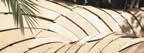
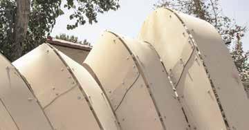
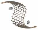
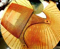
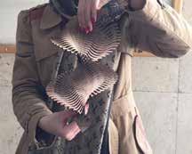
The “Hinge” technique involves a specialized cutting approach used on rigid sheet materials to introduce flexibility along certain axes. For example, as shown in the images, these curved forms were created from rigid plywood sheets, cut in a specific pattern to achieve flexibility.
The workshop was organized into three phases: Familiarization, Product Development, and Final Paneling. In the first phase, after an introduction to the hinge concept, students were tasked with designing a parametric hinge pattern and testing it on small pieces of cardboard. This trial-and-error phase lasted one day.
In the next phase, spanning one and a half days, teams of 5 to 8 students selected a product theme, such as a lamp, and crafted prototypes using cardboard to better understand the technique.
The final phase, which focused on paneling, lasted four days. In this phase, students were instructed to design architectural panels for applications such as interior curtain walls, partitions, or exterior shades, using only 3mm plywood sheets. Due to limited space here, only a few of the workshop’s outcomes are displayed.
You can find the complete results and progress on the official page of the workshop, accessible to anyone interested: https://trello. com/b/KG2OyAKR/hinge-paneling-workshop
Above: First step, Familiarity, samples created by students.
Below: Product step
Below: Final results.
COMSTRUCT
Kish, Iran | 2015 Summer Role: participant
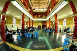
During a two-week workshop on computational structures held at the Contemporary Architects Association in Tehran, Iran, I, along with 24 students and five instructors, used Rhino, Grasshopper, and Karamba to design and build a pavilion. The workshop aimed to explore material behavior, element directionality, and the structural potential of complex geometries. Fabrication methods, tools, and materials were limited due to 20 years of embargo on Iran, making it challenging to access the latest industrial machinery in Tehran.
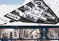
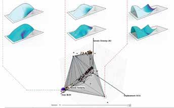
The venue, located in a converted residential house, featured an unused and empty swimming pool in the front yard. The task assigned to workshop participants was to design a structure to cover the 4x10m pool, transforming it into a dynamic exhibition space. To achieve this, the parametric FEM program Karamba was used to aid design development, with a four-step structural analysis leading to the final optimized design:
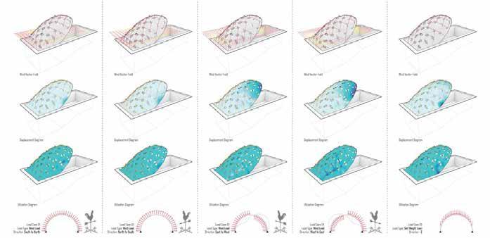
Shape Optimization: The first step involved finding an optimal shape that accounted for the site’s boundary conditions and material usage.
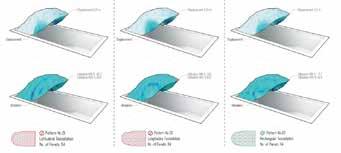
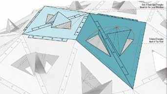
Surface Discretization: In the second step, the surface was divided into different folding patterns to increase stiffness through added inertia.
Gravity Load Analysis: The third step involved reanalyzing the folded shape under gravity load. Each triangular panel’s utilization was assessed, and hole sizes were differentiated in the center of each panel pair accordingly.
Final Structure Assembly: In the final stage, a zig-zag cable pattern joined the bent triangles, forming a three-dimensional tension truss. Additional load cases were introduced, combined with the self-weight, to simulate structural behavior under snow and wind loads.
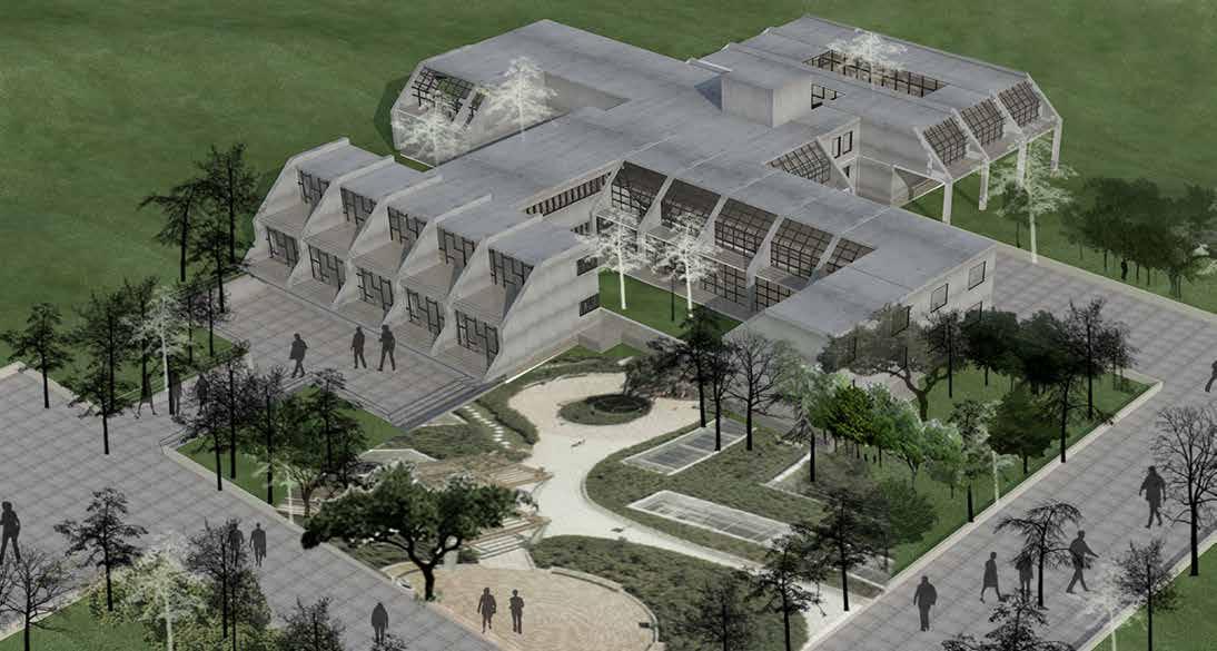
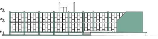
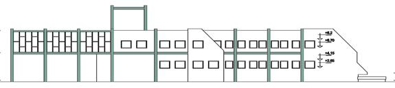
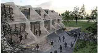
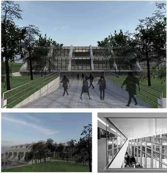
AGRONOMY SCHOOL
Karaj, Iran | 2013 Spring
M.A. Design Studio 2
Role: Designer
According to the project brief for a modular agronomy faculty, this design must not only meet the requirements of the school and small agricultural units as various laboratories, but it also needs to be designed with modular structural elements. The site is located in Karaj. The faculty’s position divides the site into four main agricultural fields, and its configuration creates several small units for student projects.
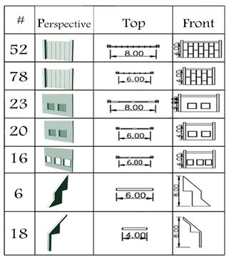
The goal of modular design in this project is to minimize the types of elements while maximizing the frequency of each type. The structural elements and their frequencies are shown in the table. Horizontal elements are limited to lengths of 8, 6, and 4 meters, while vertical elements are limited to 8 and 4 meters. Designing varied spaces within these constraints was another challenge in the design process.
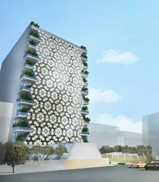
IPM FACADE DESIGN COMPETITION
Tehran, Iran | 2016 Spring Role: Co-Designer
One of the leading companies in construction and refinery management in Iran, IPMI, is responsible for some of the most prominent projects in this field. The company’s headquarters, located in Tehran, the capital of Iran, announced a competition to design a new façade for their main office building.
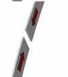
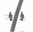
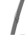
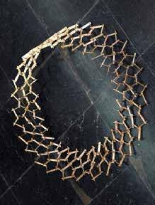
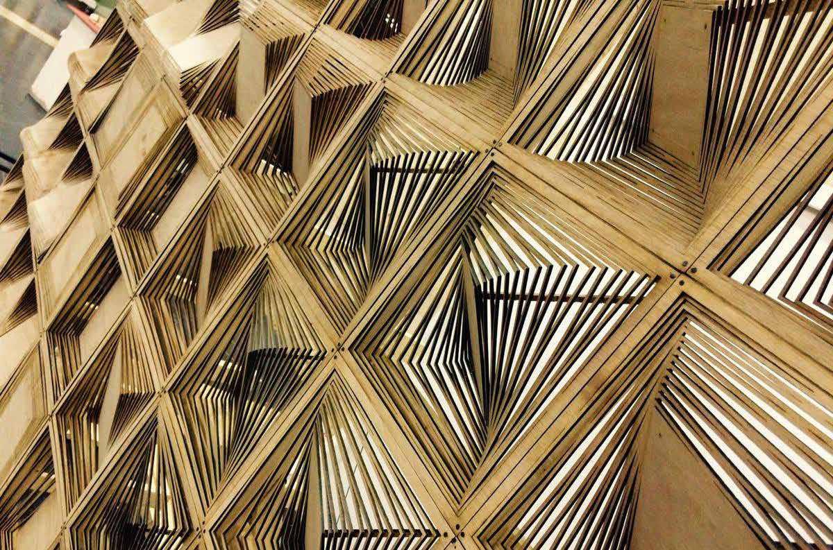
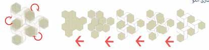
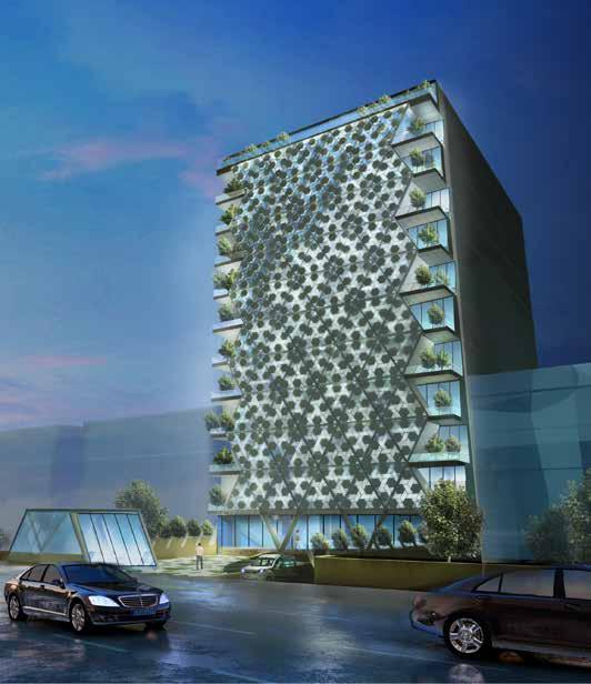
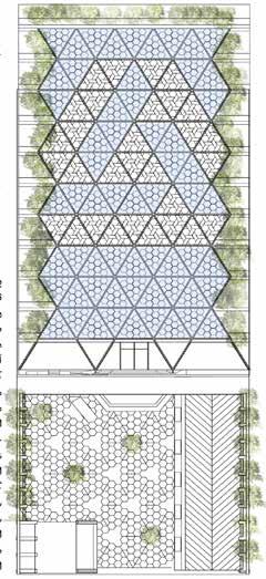
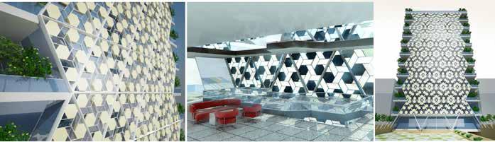
This project focuses on a façade covering the outer skin of the office building, designed to reflect the company’s core values of movement and advancement in Iran’s crucial industrial sector. The concept centers on a kinetic façade that aligns with the building’s architectural plans.
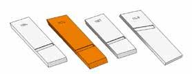
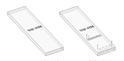
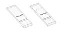
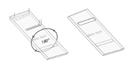
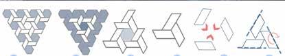
The design draws inspiration from the company’s logo, which consists of three parallelograms representing a sense of movement in a static form, akin to the principles of Gestalt movement. The desired façade features both a localized control system and an integrated kinetic mechanism capable of generating various patterns. These patterns adapt according to sunlight and shading requirements, with the ability to create a unified pattern for special occasions aligned with the office’s programmatic needs.
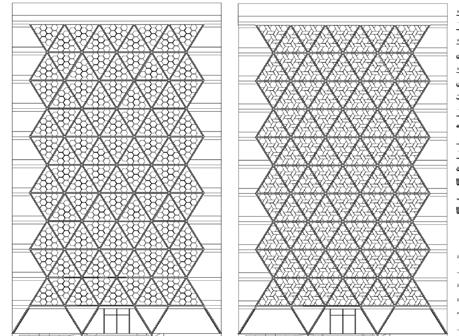
The façade’s primary pattern is divided into 90 large triangular modules, each containing three kinetic logo shapes and six hexagons. Each triangle module can provide coverage ranging from less than 30% to over 90%, maximizing the façade’s shading potential. The kinetic envelope operates through in-plane rotating actuators that switch between different patterns by overlapping the parallelogram and hexagon shapes. Additionally, perimeter modules lead to large balconies that extend the greenery from the ground level up to the rooftop garden, creating a green continuum across the building.
INSTITUTE FOR THE INTELLECTUAL
DEVELOPMENT OF CHILDREN AND YOUNG ADULTS
Karaj, Iran | 2010 summer
B.S. Final Project
Role: Designer
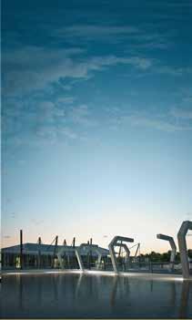
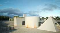
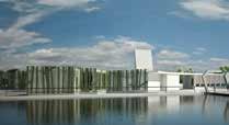
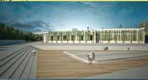
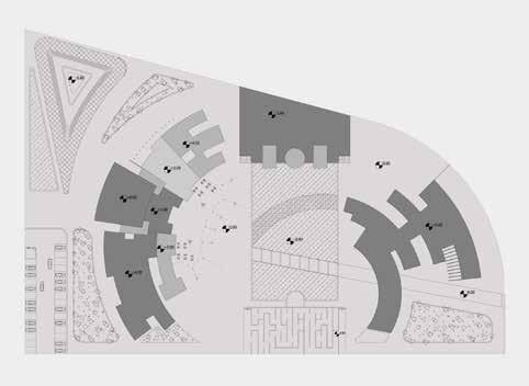
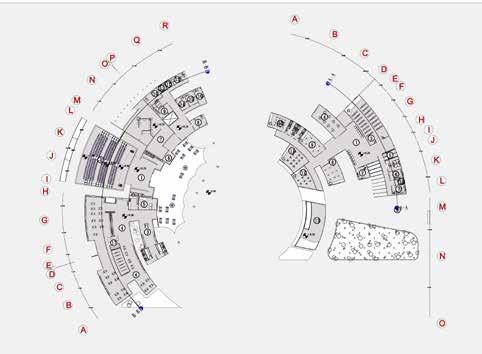
This project involves designing the building complex for the Institute for the Intellectual Development of Children and Young Adults in Karaj. This institute aims to help children improve and develop their abilities in various areas, including physical, psychological, and social realms. Children’s needs, their requirements, and the local context serve as the primary design concepts for this project.
To address the needs of both children and youth, the complex features two separate cores. One core is dedicated to children, with spaces for classes, workshops, playgrounds, and more, while the other core contains a library, conference hall, indoor and outdoor theaters, a café, and additional facilities. A large, shallow pond—symbolizing purity and knowledge in my country— separates these two cores, with a suspended light bridge connecting them.
The building heights are minimized to suit the primary users (children) and to integrate with the green site plan. The building envelopes feature dendroid decorations to blend with the natural environment. Dynamic form and ample light access are the principal factors guiding the configuration of the buildings and the site plan.