10 minute read
AMATEUR AIRCRAFT GONSTRUCTORS' GUIDE


by Arthur W. J. G. Ord-Hume P.q.nr V.
Aircraft Woodwork
Before dealing with actual carpentry, there are two dumb assistants who each play a vital part in woodwork. They are therefore worthy .of detail. One is the brad (known variously as .gimp pin, tack or nail) and the other is the screw.
The aircraft brad is a sharp-pointed brass nail with a flat head. It is available in lengths from * irr. to I in., and in thickness from 22 S.W.G. to 18 S.W.G. It is different from the commercial nail in that its flat head does not cut the surface of the timber when it is driven home. This flat head also increases the pressure which the nail can exert on the wood.
As a general rule, brass brads are used only to secure a joint until it is dry. When attaching plywood to a structure, it is common practice to tack it on with brads and remove them when the glue is dry. With modern synthetic resin glues, no great advantage is to be gained by leaving them in place although if they are they will not corrode or damage the wood by their presence.
In place of brads, ordinary staples may be used where they can definitely be removed after the glue has set. For the use of staples, a good stapling machine (such as any of the Velos office models) should be bought and the base either folded back or removed altogether by the withdrawal of the pin at the joint. The machine is then held firmly in contact with the wood and the staple driven home by pressing the knob with the other hand.
In the removal of brads or staples, exercise care not to damage the fibres of the wood in the process. A screwdriver with a cleft in the blade and the end bent through 60' is ideal for the job.
The wood screw is used for the additional attachment of certain parts such as wing tip bows, inspection panels, hinge seat members and so forth. Screws for aircraft use are made of brass and may be cadmium plated to resist corrosion. They are available either roundheaded or countersunk and should only be used as specified on the drawings.
Wood screws are designed to cut their own threads in the timber and they derive their holding power from these threads. If the screw is driven into the wood without a pilot hole, the timber may well split. If the pilot hole is too big, the threads cut by the screw will be insufficient to hold the screw tightly.
Pilot holes for screws should be drilled to enable the screw to be used to its maximum advantage. Two drills are necessary-one to drill the hole for the shank of the screw and the other, smaller in diameter, for the threads.
The first hole should be very slightly smaller than the diameter of the screw shank. If it is too large the shank will not be a tight fit and the entire load will be thrown upon the head of the screw which may pull through the timber.
If the clearance hole is too small, the shank will bind so tightly that the threads will be unable to draw the screw into the hole and they will ream out the second hole.
This second hole again must be of the correct size to allow the threads to get a proper grip in the wood. If it is too large, all the wood necessary for the screw to bite into will have been removed and it will not hold. There again, if the hole is too small, the wood is likely to split.
Also of importance is the length of this second hole. If it is too short, the screw may tend to hold the members apart or fail to draw them tightly together. This is particularly the case with hard woods.
Carefully measure the screw to be inserted and select two drills accordingly. Il many screws of the same size are to be used, fit a stop ,on the drill shank so that all the holes are of the same depth. A piece of wood such as a dowel rod of the right length will make a good drill stop.
If the screw to be used is a countersunk one, use a proper wood screw countersinking bit. Woodscrew heads have an angle of 90". Do not use an ordinary large twist drill as a countersinkthe head angle is 120' and also the edges of the drill will chip the surface grain of the wood.
In aircraft carpentry, there are only two basic types of joint which are used. Each of these depends on careful workmanship to enable it to develop its maximum strength.
First is the scarf joint in which the two pieces of wood are equally tapered over a precise length so that they fit together, one onto the other. The scarf joint, properly made, will at least equal the strength of the surrounding timber since it presents a very large surface for gluing. For example, a one inch square spruce strip, scarfed up out of two pieces with a one in sixteen taper have between them a glue area of sixteen square inches.
The scarf method of joining is the only method which may be used for joining or splicing spars, longerons, stringers or any other strip of timber. It is also used for the joining together of two panels of plywood to make one.
The width of a scarf is sixteen times the thickness of the wood-a piece of +" thick plywood will need a scarf one inch wide (16 times +"") and a strip of *" x f;" wood will require a twelve inch one (16 times f;").
When joining a piece of timber of unequal section such as *" x t", one can either scarf the $' face 8" long, or the $" wide face 14" long. For ieasons of economy, however, it is usual to make the scarf as short as necessary. In all cases, however, timber which has one face three or more times width of the other must be scarfed on tl-re broadest face-for example a plank 4" x l" would have a 4" wide scarf 16' long.
The accurate cutting of a scarf requires a really sharp smoothing plane with a very fine setting. After marking out for the scarf using a carpenter's square, rule and pencil, the timber may be roughly cut to the angle of the scarf using an ordinary tenon saw. Care must be taken however to avoid splitting the wood during this operation.
Secure the required portion of the timber to the bench with the longest edge of the scarf lowermost and supported by a piece of scrapwood with a straight edge. This is so that as the thin edge is prepared, the end is supported and remains level with the lower edge of the timber-if it is not supported, it will bend down under the weight of the plane and the scarf will not be accurate. Firmly locate the timber and the supporting board to the bench with G clamps to prevent it moving during planing.
The cutting of the scarf will be facilitated if the plane is held at a slight angle to the direction of the cut so that the wood is sheared off. This angle may be between about 15' and 20". When scarfing plywood, it is important to keep the cutting edge at a convergent angle to the cut or else the blade will dig in and chip away this very hne edge. The plane sliould be set to give the finest possible cut. A coarse setting will chip the wood and fail to produce good work.
Take great care whilst planing to ensure that the surface being produced is level and true. Use a square and a rule and check frequently. When both pieces of timber have been preparcd, try them together as a final check for accuracy.
In scarfing plywood, the finished edge should show the three laminations as straight bands. The glue used in the manufacture of plywood is a synthetic resin which will show up as two parallel, straight dark bands. If these glue lines are not parallel but are converging, wavy or kinked, then the scarf is not true. This can be caused by faulty planing or, as usually the case with kinks, by an uneven base board, dirt on the board under the plywood, or by the presence
A L{H,NATED CI,PYEb FoRHER WMT A PLY FACE EAC'I SDE rYPtcAL WING RtB CoxsTRucrloN
CLAMP,r.lq BLocK S h,Arcb PAFE
SHoRT-SPAINEb PAY 7A-c(rNQ SIPIP
LOCATINS BRAbS-\- .)
TooL FoR REHovlNCz BEAbS AND STApL.ES, tlAl(G FPonr OLb 6CREN\R.IVER, Re-rcr*reE AFrEre Bexuxq GLUETNq UP A SCARtr TO/N7 'N Ftvwoos
How To SoPPoRT PLYNoOb
WATEb PAER of knots in the base board causing the cutting edge of the plane to lift at one point.
When gluing up a scarf joint, one must apply even pressure along the total length and width of the joint. The glue should be applied ,evenly to both faces and then the two pieces rubbed together to exclude any air bubbles. Select two pieces of scrap wood several inches longer than the total length of the joint and place these one on each side. To prevent the .adhesion of glue to these clamping blocks, insert a strip of waxed paper between the block and the joint. The wrapping paper from sliced loaves of bread is ideal for this purpose ! Clamp up using G clamps at intervals to ensure adequate pressure. Achieve adequate not excessive pressure. Never put a clamp directly into contact with aircraft wood-it will press into and damage it. The load should always be spread by transmittingit through clamping blocks.
Joining plywood presents a slightly different problem. Due to the size of the panels of ply which may have to be joined, it will not be possible to clamp the two togetl-rer as detailed above. Let us suppose that the constructor has to scarf up two panels of plywood and the ,scarfed edge is twenty inches long. First of all, a batten of wood will be required about two feet long, three inches wide and about threequarters-of-an-inch thick. A strip of waxed paper is laid over this batten and one panel of plywood laid witl-r its scarf edge uppermost and approximately on the centre-line. Tack it every six inches or so to the edge of the batten. Apply glue to the joint, shuffie the other panOl onto the scarf to exclude air and line it up in the correct position. Secure it to the batten with tacks as the other piece. Place a strip of waxed paper over the joint and prepare a strip of plywood as long as the scarf joint and about 1| inches wide. This must be short grained so that it will press the full width of the joint. Line this strip up and proceed to tack it at half inch intervals along itg centre line (the centre line of the scarf joint). Use brass gimp pins of sufficient length to go right through the joint and well into the base batten. 16
When the glue has set, the tacking strip may be removed and the odd securing brads withdrawn. If properly executed, the joint should require only a light sanding to remove any surplus glue.
We have now learned to use one of the most versatile applicetions of light clamping-the tacking strip. It is a method of applying sufficient pressure to set a glued joint when it is either impractical or impossible to use a clamp or other means of pressure application. When covering the leading edge of a wing, for example, it is impossible to use clamps for securing the plywood since both sides are not accessible. In such cases the tacking strip has to be used.
Strips may be prepared from offcuts of *", &' or t' ply and should always be short grained unless they are for special use. The whole idea of the tacking strip is that the fibres of the major (outer) veneers should press down on the joint or centre of pressure application. This means that the grain should be at right angles to the line of pressure wanted. Do not forget that any glue squeezed out of a joint will stick to a tacking strip or clamping block. Use waxed paper wherever there is a risk of this happening. (continued).
HOW TO WIN THE KING'S CUP
WITH A LITTLE 'UN-Cor/inueCfront page 5
The weather af,ter the Air Races trapped us at Coventry for some time, but when we got her home we convened a meeting and with the generous assistance of the Kemsley Flying Trust we are now having a Belfair made out of the Tipsy. This is the closed cockpit version of course, sorrowful as we are to lose all that lovely fresh air and rain economic considerations force us to accept the fact that paying customers prefer to fly under glass.
We shall be back at the Air Races next summer, Number 46 as before, but if anyone has a mqtal prop for a Walter Mikron engine (X4 if possible), for mercy's sake sell it to us. Our wooden one is about as much use as a spoon.
Popular Flying, January February, 1958
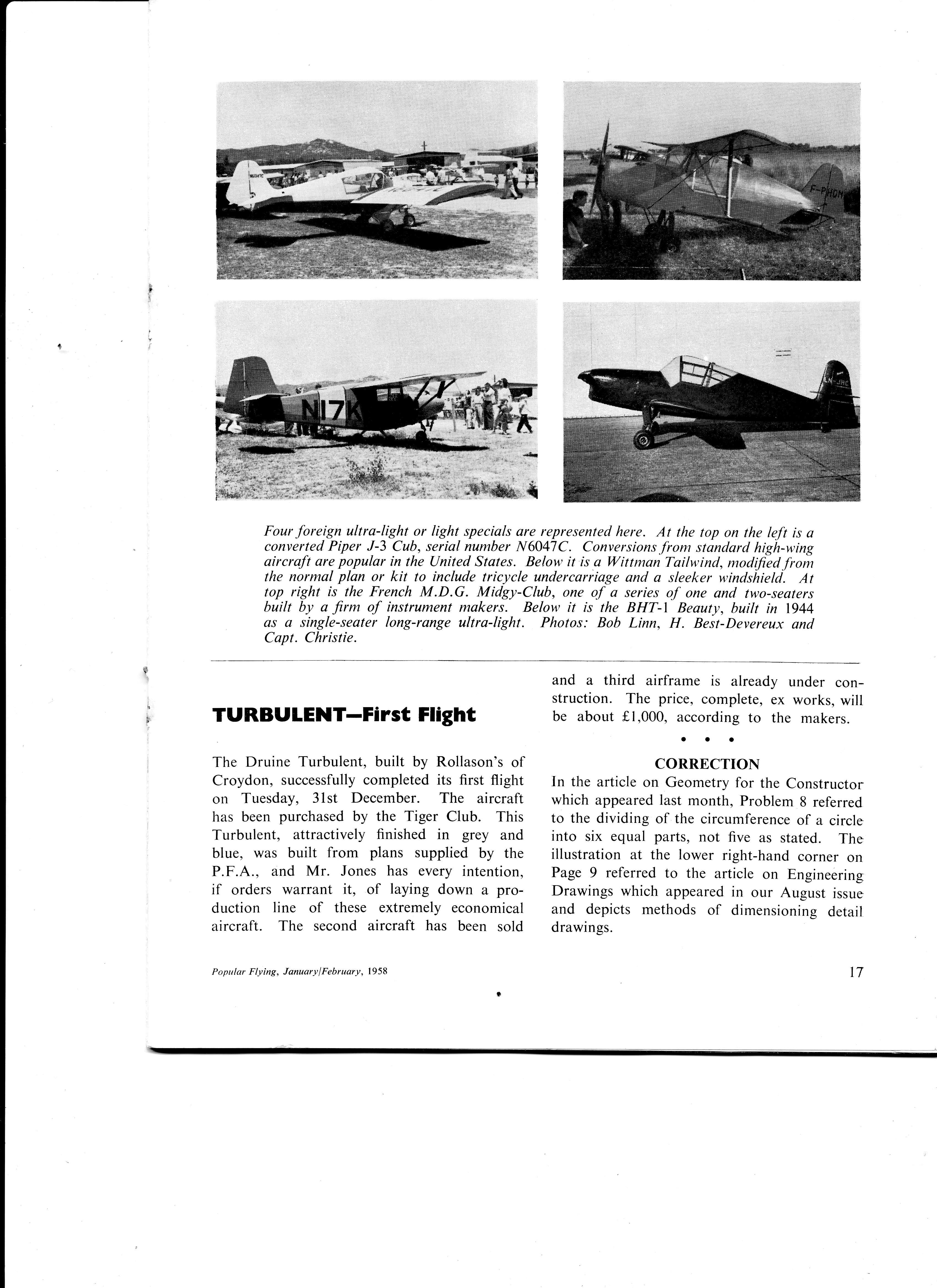
Four foreign ultra-light or light specials are represented here. At the top on the left is a converted Piper J-3 Cub, serial number N6047C. Conversions.from standard high-wing aircraft are popular in the United States. Below it is a Wittman Tailwind, modified from the normal plan or kit to include tricycle undercariiage and a sleeker wtndshield. At top right is the French M.D.G. Midgy-Club, one of a series of one and two-seaters built by a firm of instrument makers. Below it is the BHT-I Beauty, built in 1944 as a single-seater long-range ultra-light. Photos: Bob Linn, H. Beit-Deyereux and Capt. Christie.
TURBULENT-First Flight
The Druine Turbulent, built by Rollason's of Croydon, successfully completed its flrst flight on Tuesday, 31st December. The aircraft has been purchased by the Tiger Club. This Turbulent, attractively finished in grey and blue, was built from plans supplied by the P.F.A., and Mr. Jones has every intention, if orders warrant it, of laying down a production line of these extremely economical aircraft. The second aircraft has been sold and a third airframe is already under construction. The price, complete, ex works, will be about f1,000, according to the makers.
co**uctro*
In the article on Geometry for the Constructor which appeared last month, Problem 8 referred to the dividing of the circumference of a circle into six equal parts, not five as stated. The illustration at the lower right-hand corner on Page 9 referred to the article on Engineering Drawings which appeared in our August issue and depicts methods of dimensioning detail drawings.


