12 minute read
Engineering Matters


Including: Engine mount maintenance, propeller bolts and correct torque values, Permit revalidation applications…
Welcome to Engineering Matters – the section of Light Aviation that is dedicated to discussing all manner of topics concerning both technical and operational aspects of the LAA fleet. If you have anything to say that you think would benefit others, then please email words and pictures to LAA Engineering at engineering@laa.uk.com
Engine mounts
Engine mounts have to cope with a lot as they transmit the loads from the engine and propeller, through to the airframe.
It is not uncommon for the taildragger variants of the Van’s RV engine mounts to suffer from cracking, as they are also the mounting points for the main undercarriage, and are therefore subjected to the associated loads from that area, too.
There have been two examples found recently on Rotax-powered aircraft where engine mount tubes have cracked through completely and not at the more common failure area of a weld cluster.
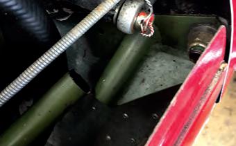
LAA Inspector, William McMinn, reported that one of the aircraft he oversees is a Sting TL200 UK that has flown for approximately 1,000 hours. After landing, recently, the engine started to run roughly with a lot of vibration. Once the engine cowlings had been removed the owners discovered a fractured engine mount tube. The engine mount is to be replaced by a new one.
It is always good to not instantly jump to conclusions, but look at the complete picture. A vibrating or rough running engine might be a physical issue with the engine itself, such as an ignition system defect or a failed cylinder. It can also be as a result of something like a failed engine mount, which allows the engine to vibrate and that in turn upsets the engine, causing it to run rough. With the Rotax 912 series of engines, the carburettors do not take kindly to excessive vibration as it can upset the fuel delivery resulting in a rough running engine – a result not cause.
The other aircraft with a failed mount was a Zenair CH CH 601UL, with around 500 hours total time flown. The owner spotted the failed engine mount tube on the pre-flight check. It is not always practicable (i.e. easy!) to remove engine cowlings on a ‘Check A’, but it can certainly pay dividends at times, such as in this case.
As engine mounts are stressed items, a repair should be carried out in accordance with the requirements of LAA Technical Leaflet TL 3.05 with an LAA/MOD 8 Repair Proposal submitted to LAA Engineering.
There are various ways to mitigate potential problems with engine mounts, such as having propellers dynamically balanced and ensuring that the engine shock mounts are in good order. The shock mounts can easily be contaminated by oil and suffer if exposed to excess heat, such as being close to the exhaust system.
It has long been an industry standard on certified aircraft to paint engine mounts black. A lighter colour is a much better idea, as cracks tend to appear as a dark line, so are not easily spotted on something painted black. As was mentioned last month in Engineering Matters, powder coating can also mask defects.
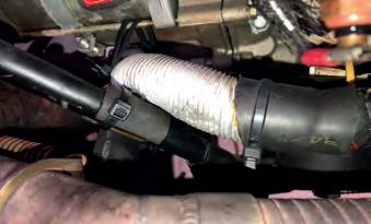
Engine mounts are often used as a convenient place for securing hoses and wiring looms and whatever is used as the securing device, ensure it cannot move, as it is this relative movement that will lead to chafing, removal of the protective coating, leading to corrosion issues. Suitable securing methods might be rubber coated ‘cushion clamp’ P-clips or even the relatively new invention (1956) of cableties. Some will no doubt reel away in horror at the thought of using cable ties but they do work provided decent quality ones are used and fitted correctly.
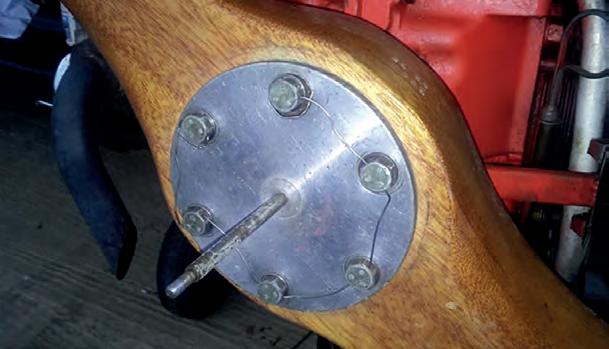
Propeller bolts and torque
LAA Engineering design engineer, Andy Draper, deals with the majority of the propeller change modification applications and has been looking into the correct torque values for propeller attachment bolts.
There are a number of factors involved in ascertaining the correct torque of any bolt and this is particularly important when it comes to propeller attachment bolts.
Not only is it the strength of the bolt that is important in working out the correct torque value but also the material used for the actual propeller. For instance, there have been a multitude of different woods used in propeller manufacturing over the years and each type of wood will have a specific ‘compression strength across the grain’ value, i.e. a ‘crush’ value.
The primary source of information to correctly install a particular propeller should be the propeller manufacturer. If the propeller manufacturer does not specify the attachment bolt torque, then the next source of information should be the airframe manufacturer and then, the engine manufacturer.
If all other attempts at finding out the required information fails, then it must be ensured that the maximum torque value for the bolt is not exceeded. The type of bolt used should also be specified by the propeller, airframe or engine manufacturer. When smaller diameter bolts are specified (it is not uncommon to see ¼in AN bolts called up on the smaller airframe/engine/propeller installations), the required torque can be quite close to the maximum allowed for that bolt.
Various locking methods are used for propeller bolts – sometimes they use nuts (normally of the self-locking variety, something else to be considered if calculating a torque value), and at other times they screw into threaded bushes pressed into the engine crankshaft propeller flange. Quite often, propeller bolts are wire locked, which in itself might be considered a bit of an art form, but is easily achievable by everyone, with a bit of practice.
Bolts produced specifically for propeller attachment normally have a longer threaded section than standard bolts. Something to be considered if the installation calls up the use of a standard bolt.
Bulldog fatigue meters and Tiger Moth tie-rods
Mark Miller of de Havilland Support Ltd has good news for Bulldog owners, the fatigue meter overhaul capability is shortly to be restored and DHSL will be issuing an associated Service Letter shortly. Also, DHSL have had 300 Tiger Moth tie-rods manufactured and should be available for purchase soon.
ELT retention by velcro strap
Although intended primarily for certified aircraft, the FAA have issued Special Airworthiness Information Bulletin HQ-13-32 concerning Emergency Locator Transmitters ELT) that are secured by ‘hook and loop’ (commonly referred to by the trademarked name of ‘Velcro’) straps and mountings.
EASA has highlighted this FAA SAIB by issuing its own Safety Information Bulletin SIB 2013-04R1.

From the EASA SIB: “In several aircraft accidents, ELTs mounted with textile style fasteners have detached from their aircraft mounting. The separation of an ELT from its mount could cause the antenna connection to sever, rendering the ELT ineffective. The separation of an ELT from its mounting may also cause damage to other parts of the aircraft or pose a risk of parts detached from aeroplanes.”
‘Hook and loop’ fasteners are used in a variety of ways in light aircraft, including for the ‘temporary’ installation of handheld radios and tablets. This recommendation by EASA is relevant wherever this method of installation is utilised:
“EASA recommends in addition that textile style fasteners are inspected for signs of damage, loss of function, wear, or onset of deterioration over its entire length but especially where contact to other materials (buckles, loops, rings) or where it is glued or welded.”
Operating limitations document
An Operating Limitations document is issued for most LAA administered aircraft and are airframe specific. Currently, the types that are not issued with an Operating Limitations document being factory-built gyros, factory-built microlights and aircraft still operating on an EASA Permit to Fly and the Permit to Fly will include the relevant information.
The Operating Limitations document forms part of the legally required Permit to Fly documentation and is directly referred to in the actual Permit to Fly:
‘This Permit to Fly is issued subject to the Conditions listed on the subsequent pages and Light Aircraft Association (LAA) Operating Limitations.’
From the emails and telephone calls received, it is apparent that many owners do not realise the importance of the Operating Limitations document or indeed even know where the one is for their aircraft.
When aircraft are sold, the new owners should ensure that all the required documentation is supplied, including the Operating Limitations document. Replacements are available from the LAA for a £20 fee.
Kitfox low fuel alert sensor
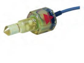
Kitfox owner, Dave Piercy, has alerted us (if you’ll excuse the pun) to a failure in his aircraft’s low fuel warning system. The fuel system header tank has an optical sensor fitted that should send a signal, I presume, to a warning light when the sensor is not immersed in fuel.
While refurbishing the aircraft, Dave tested the system and found it wasn’t working. On removing the sensor, he found that it was showing signs that it may have possibly been adversely affected by contact with fuel, although, according to the manufacturer’s data, that model (Carlo Gavazzi VP03E) should be ‘resistant to various solvents’ and that it has ‘high chemical resistance to most acids and bases’.
Dave reports that: ‘The sensor will have been ‘dry’ for the past two years, as the aircraft has been refurbished. The sensor has never seen any E10 fuel, and my testing has shown little ethanol in the forecourt fuel up to 2020 when the Kitfox was flying. Mogas has been used in the aircraft, almost exclusively’.
Other Kitfox owners using a similar system might contemplate testing their own low fuel warning system and even remove the low
Interesting airspeed indicator failure
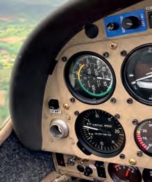

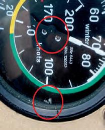
While carrying out a check flight on a Europa, LAA Inspector, Toby Willcox, was somewhat surprised to see the air speed indicator scale spin round and slip to the bottom of the instrument.
It would appear that, for whatever reason, the scale attachment screws had worked loose and the (normal) vibration in the climb was enough for them to finally drop out. It appeared that the needle was clear of the scale and acting as it should but to be on the safe side, Toby ‘carried out a stall, noted stick position and noise and just approached with the stick forward of that and the wind/engine noise slightly
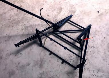
EuroFOX Wing trailing edge
Many of the EuroFOX aircraft on the LAA fleet work hard for a living, operating as glider tugs and flying more flight ‘cycles’ than their pleasure flying siblings.
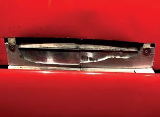
There have been a couple of instances reported, the latest by LAA Inspector Nick Stone, of wing trailing edges cracking. The recent discovery was made by a diligent
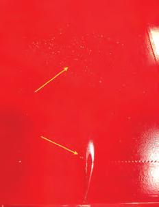
Right fuel sensor to check on its condition. louder but not too loud!’. The subsequent landing was uneventful. Toby’s advice to himself and others following this uncommon failure, is to always note the ASI needle position required for an approximate approach speed prior to take-off if there are secondary instruments and equipment installed (this aircraft had a ‘SmartASS’ ‘speaking air speed indicator fitted) make sure they are turned on – just in case. Toby had not switched on the SmartASS on this flight as he found it could be a distraction but with hindsight it would be better to turn it on and turn the volume down. gliding club tug washing team who noticed some small flecks of paint missing on the upper surface of the starboard wing, aft of the fuel tank.
The initial indication of a problem was the missing paint on the top surface of the EuroFOX wing.
There are two further things to consider with Dave’s discovery. Firstly, it highlights potential issues with components that are in contact with fuel – from seals and O-rings, to hoses, valves and sensors.
The second point is the checking of warning systems. It might be a bit of a pain to routinely drain a header tank to ensure a low fuel alert system is functioning but how else can it be tested? Low oil pressure warning lights can be checked before engine start and similarly, alternator/charging fail lights.
With the multitude of EFIS monitoring systems now in existence, there are many options for the installation warning systems and checking that they function correctly should be included as part of the routine maintenance tasks and their serviceability must not be assumed.
Further inspection showed that the trailing edge was flexing and felt no longer attached. On removing the fabric in the area, three sections of the trailing edge fell out. The cause may be localised turbulent air flow as a result of propeller wash and exacerbated by the aircraft’s operation as a tug and all that it entails.
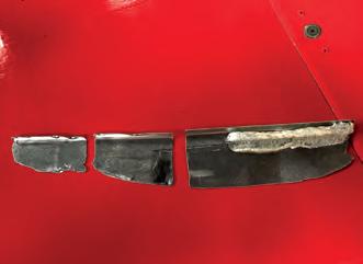
The trailing edge in this instance is not there for structural purposes, it is more to keep the shape of the wing as a fabric attachment area.
FWR-1 Permit to fly revalidation applications
Part of the future planning in LAA Engineering is to head towards a more ‘online’ Permit to Fly revalidation process. Plans are afoot to make some steps in this direction in the coming months, but a fully online system will need careful evaluation and planning, and is a longer term project for the Association.
Currently, every LAA administered aircraft has its details and records on a database that is used all the time by LAA Engineering. It is for internal use although some aspects of the database can be accessed by owners by logging onto the LAA website.
Part of the FWR-1 Permit to Fly revalidation application (Section 2: Aircraft Document Check’) requires the Inspector to complete and sign that the installed engine and propeller are as accepted on the aircraft’s Operating Limitations document, the only Permit to Fly documents where this is stated.
It is quite common to see that owners have filled in this section on behalf of the Inspector and it is even more common to
LAA Engineering housekeeping
have incorrect or missing information included in the FWR-1 Section 2: Aircraft Document Check. The Inspector is taking responsibility for the completion of this section.
The completion of the Aircraft Document Check is not supposed to be a copying exercise from a previous Permit to Fly revalidation application but an actual physical comparison of what is on the Operating Limitations document, against what engine and propeller are actually bolted to the aircraft.
When an FWR-1 is received, the information included in the Aircraft Documents Check section, is compared to that stated on the aircraft’s Operating Limitations document and on the LAA Engineering database. If there are any differences between the Operating Limitations document and what is recorded as installed on the FWR-1, these issues will need to be resolved before the Permit to Fly can be revalidated.
To ensure that, as and when the time comes to have a more ‘automated’ system
Operating limitations In addition to the piece in this Engineering Matters about Operating Limitations documents, please note that to ensure that there is only one issue of an aircraft’s Operating Limitations document in existence, when the document is being reissued, owners will be asked to return the original Operating Limitations document to LAA Engineering or send in a photograph of the Operating Limitations document having been cut up. This has to
LAA Engineering charges
LAA Project Registration
Kit Built Aircraft £300
Plans Built Aircraft £50
Initial Permit issue
Up to 450kg £450
451-999kg £550
1,000kg and above £650
Permit Revalidation
(can now be paid online via LAA Shop)
Up to 450kg £170
451-999kg £220
1,000kg and above £260
Factory-built gyroplanes* (all weights) £275
*Gyros note: if the last Renewal wasn’t administered by the LAA, an extra fee of £125 applies
Modification application
Prototype modification minimum £60
Repeat modification minimum £30
Transfer for the Permit to Fly revalidations, the information stored on the database must be 100% accurate. This in turn relies on the correct information being provided on the FWR-1 application. be the original, laminated, Operating Limitations document as supplied by LAA Engineering – not a photocopy.
Therefore, please do check the accuracy of the information submitted on the application thoroughly and do not be surprised if an email is received requesting further information on an engine or propeller that is currently installed if the recorded information is incorrect.
Despite the high numbers of Permit to Fly revalidation applications being received this time of year, we do still try to process them within a day or two of receipt.
If there are issues with an application, this can lead to delays whilst emails are written and replies received.
Please check the whole FWR-1 form very carefully before posting it off to LAA Engineering – and don’t forget to check the correct postage fee is paid. Underpaid post gets diverted en route by Royal Mail and can take a week or more to appear.
LAA Engineering response times We are now into the busiest time of year for LAA Engineering. Please be understanding if emails take longer to be replied to and applications are not dealt with quite as quickly as you might like. ■
LAA Fleet Summary
New Projects Registered in 2022: 29
Permit to Fly First Issues in 2022: 26
(from C of A to Permit or CAA Permit to LAA Permit)
Up to 450kg £150
451 to 999kg £250
1,000kg and above £350
Four-seat aircraft
Manufacturer’s/agent’s type acceptance fee £2,000
Project registration royalty £50
Category change
Group A to microlight £150
Microlight to Group A £150
Change of G-Registration fee
Issue of Permit documents following G-Reg change £55
Replacement Documents
Lost, stolen etc (fee is per document)£20
PLEASE NOTE: When you’re submitting documents using an A4-sized envelope, a first-class stamp is insufficient postage.
Permit to Fly Revalidations - 2022: 929
Recent Alerts & AILs (check the LAA website for further details)
Zivko Aeronautics Inc. Edge 360, Edge 540 and
Laser Z200: Aileron Centre Hinge Attachment
CAA MPD: 2022-001
LAA Alert: A-001-2022
MT-03, MTOsport, MTOsport 2017, Calidus and Cavalon: Rotor Blade Inspection/Replacement/
Life-Limitation
CAA MPD: 2002-002
LAA Alert: A-002-2022
TLAC Escapade and Sherwood Scout: Seat locking and Secondary Seat Restraint
CAA MPD: 2022-004-E
LAA TSB: TSB-001-2022
Europa: Door Latch System Stop
CAA MPD: 2022-003
LAA AIL: MOD/247/012
LAA Alert: LAA/AWA/21/08
Adjustable Seats in General Aviation Aircraft
CAA Safety Notice SN-2022/001: Security and locking of adjustable seats


