Table of Contents
Heavy Duty cable trays S235 - S240 Pgs 4 - 5
Heavy Duty cable trays S428 - S438 Pgs 6 - 7
Component disposition, splices, bends, crosses and tees . . . . . . Pgs 8 - 9
Assembly guidelines

Pgs 10 - 11


Heavy Duty cable trays S235 - S240 Pgs 4 - 5
Heavy Duty cable trays S428 - S438 Pgs 6 - 7
Component disposition, splices, bends, crosses and tees . . . . . . Pgs 8 - 9
Assembly guidelines
Pgs 10 - 11
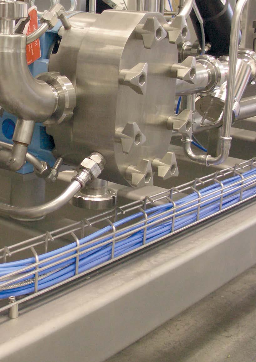
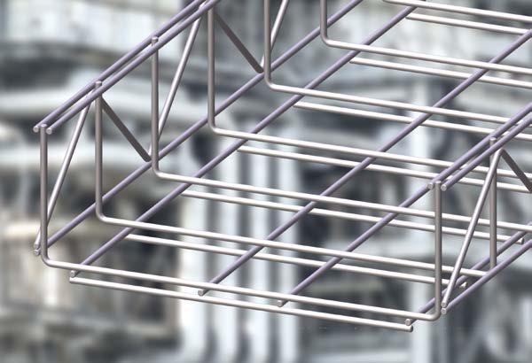
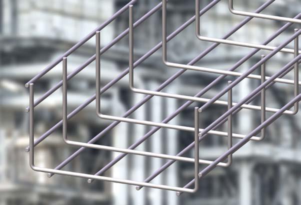
SILTEC cable routing system has been developed with optimal function in mind and with emphasis on simplicity and accessibility for the purposes of thorough cleaning and heat dissipation .
SILTEC cable routing system is made up of durable components of steel of highest quality, resistive to corrosion and with excellent chemical resistance .
SILTEC cable routing system is suitable for:
• The Food industry
• The Chemical industry
• Machine builders
• Office and computer environments
• Electrical installations in general
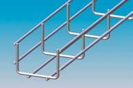
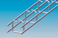
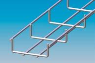
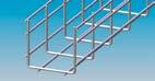
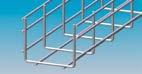
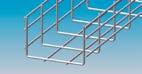
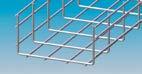
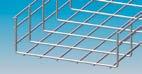
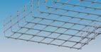
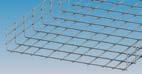
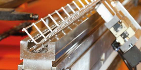
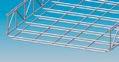
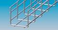
Cable trays are delivered in lengths of 118 inc . / 3000 mm . Width varies from 1 inc. to 24 inc. / 25 mm to 600 mm, and height from 1 inc. to 5 inc. / 25 mm to 125 mm.
Cable trays with custom measurements are made upon request .
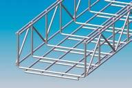
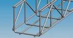
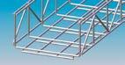
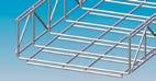
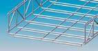
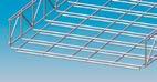
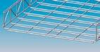
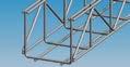
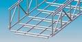
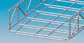
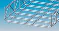
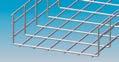
All cable trays are made of round material which is gentle on cables, tubing, installers and maintenance personnel .
SILTEC cable trays are produced in Stainless steel
SILTEC cable routing system solves issues with the transport of energy in cables – simple, effective and environmentally correct .
- Comes with the following wire cable tray types
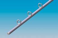
In addition, we offer a large number of specialty trays and a comprehensive program of assembly parts, mounts and accessories .
4.0"
4.0"
4.0"

Dividers
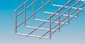
Elbows
Vertical Bends
Radius Bends
S273 T S87+ S90 x 2
S245 = 5 71"
S246 = 9 65"
S247 = 13 .58"
S248 = 17 52"
S249 = 21 46"
S250 = 25 39"
S90 + S42 + S87 x 1
S273 - 118.11"
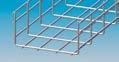
Tees and Crosses
Siltec USA, Inc.
6101 - 23rd Drive West, Suite B, Everett, WA 98203, USA
Phone (+1) 425 328 1006 www siltec us / siltec@siltec us