7 minute read
Permeable paving design and installation guidelines


Permeable Design Pro Software
Design permeable interlocking pavements with ICPI’s Permeable Design Pro Software (PDP):
Advertisement
• Integrates hydrologic and structural solutions. • Includes rainfall data for 12 major cities in South Africa. • Provides base thickness solutions from calculating inflow/outflow & traffic loads. • Design sustainable storm water management with PICPs. • Design solutions with CAD cross section outputs.
The Permeable Design Pro (PDP) software application is used to develop permeable aggregate base and subbase thickness solutions for supporting traffic loads, and for water storage and infiltration. By integrating both hydrologic and structural solutions, PDP helps to ensure the intended performance of permeable paving systems. PDP was developed to assist civil engineers and landscape architects to design permeable interlocking concrete pavements (PICP). The application enables the user to design PICPs for numerous applications, such as, residential driveways, commercial walkways and parking lots, paved roads, as well as industrial paving applications. Permeable Design Pro includes rainfall data for 12 major South African cities, extensive documentation and help library, onscreen mouse-over advice, as well as input error-trapping for learners.
PDP is available for purchase and download from www.permeabledesignpro.com, or alternatively it can be made available through Bosun.

Bosun’s Waterwise Permeable Paving Range
Waterwise Heavy
Waterwise Citylock
Waterwise
View more on pages 94-96
Guidelines for successful functional and structural performance of Bosun permeable pavers.
Please Note: This document is merely a guideline for the installation of the Bosun permeable pavers. Individual analysis and design of a specific site would have to be conducted by a qualified engineer. Bosun could be contacted in order to provide the services of a contracted industry expert in this field in order to assist engineers for a nominal fee.
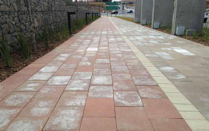
The Bosun permeable pavers bring a new dimension to aesthetic appeal and drainage capability of large areas used by pedestrian or vehicular traffic. Successful use, however, is dependent on proper design and installation. These guidelines assist practitioners in specifying and applying sound procedures. They are focused on specific requirements and are supplemental to general industry documents such as the Concrete Manufacturers’ Association’s (CMA’s) An Introduction to Permeable Concrete Blocks.
Managing water run-off
Managing water run-off is a current environmental focus, as it manages surface water by attenuation and filtration with the aim of replicating, as closely as possible, the natural drainage from a site before development.
Managing water run-off consists of: • minimising water run-off QUANTITY; • improving water QUALITY; and • providing AMENITY and biodiversity through an improvement of the environment.
There are three permeable concrete block pavement (PCBP) systems, which are commonly known as Systems A, B and C. These systems possess different drainage attributes, but visually look the same.
System A – full infiltration This system is suitable for existing soil (subgrade) conditions with good permeability and allows all the water falling onto the surface to infiltrate through the constructed layers to the water table, as shown in Figure 1. No water is discharged into conventional drainage systems, eliminating the need for pipes. This system is only suitable if the subgrade can receive the water without complications.

Figure 1. System A – full infiltration.
System B – partial infiltration This system is used where the existing soil (subgrade) is unable to absorb all the water that falls on the surface. Surplus water is then removed by a pipe drainage system in the pavement structure, as shown in Figure 2. By the attenuation achieved in the permeable sub-base, run-off – and thus the danger of flooding – is significantly reduced.
System C – no infiltration Where the existing soil (subgrade) is poor or contains pollutants, System C allows for the complete capture of all the rainfall, as shown in Figure 3. The porous nature of the sub-base functions as a storage tank, reducing peak flows through the outlet pipes leading to other surface drainage systems, such as ponds or water courses.

Figure 2. System B – partial infiltration.
Figure 3. System C – no infiltration.

Design requirements
Lower membrane:
In Systems A and B, the lower membrane should be a permeable geotextile, to allow water infiltration. This membrane should have the required strength to withstand damage when the stone for the sub-base is placed, and it should remain permeable (not clogged) during the life of the facility. In System C the lower membrane is impermeable, since it is capable of being welded to ensure a complete seal and strong enough to withstand damage (such as holes punched into it) when the porous sub-base is constructed.
Sub-base thickness requirements:
The permeable sub-base consists of a 26,5mm or 19mm single-sized crushed stone. This type of stone has about 40% of the volume of air voids, which means that 40% of the layer volume can be filled with water. If the layer is 150mm thick, it can accommodate 60mm of rainfall in the layer if there is no infiltration or outflow. This is sufficient for most rainfall events. In cases where more substantial requirements must be provided, advanced analysis techniques are available and Bosun can provide a service to assist designers. (We utilise the services of an academic in this field. The costs and timeframe of consultation would be determined by this individual.)
From a structural perspective, a 150mm permeable sub-base is sufficient to carry 1 million standard 80kN axles during the life of the facility (about 25 trucks per day) on a subgrade with a CBR of at least 15. This is adequate for most applications in the urban environment, such as access streets, parking areas and hardstands around office and residential properties.
For large projects or facilities carrying large numbers of heavy vehicles, where the implications of inadequate structural design are significant, detailed mechanistic design can be performed by specialist pavement engineers. Bosun offers a service to assist with the structural design or review designs, as mentioned above.
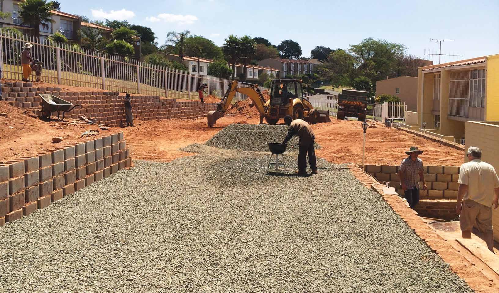
On Figures 1-3, a permeable geotextile membrane is shown as separator between the coarse stone and the bedding layer. From a functional perspective, a membrane is a feasible solution, but in practice this invariably causes problems. Before the membrane is placed, particle interlock of the coarse aggregate must be achieved by using a heavy roller with a mass of at least eight tons and preferably with vibrating capability. A one-ton walk-behind roller does not achieve particle interlock. The area to be paved must be completed so that the membrane can be placed (this is sometimes difficult to achieve on a small site). After construction of the paving, if trenching has to be done, the membrane is invariably pulled up and not reinstated after trenching is complete.
An alternative to using a geotextile membrane, yet preventing the bedding sand from disappearing into the coarse stone layer, would be to select progressively finer materials. These materials are selected using the well-known filter criteria, which is explained below. The two aggregate materials should meet the following criteria: D15 sub-base D85 bedding layer must be less than or equal to 5. where Dx is the particle size at which x% are finer. Using the example in Figure 4, D15 sub-base is the size where 15% of the sub-base is finer, namely 8mm, and D85 bedding layer is the size where 85% is finer, namely 3,7mm. The ratio of 8/3,7 is 2,16, which is less than 5 and thus satisfactory. It is advisable to check visually on site that the laying coarse particles fit into the voids of the sub-base material without excessive migration into the sub-base.
The bedding layer should have a thickness of 20mm to ensure that undue deformation does not take place, but adequate drainage occurs. The bedding layer is spread after complete compaction of the sub-base with a heavy roller to achieve full particle interlock. Compaction of the bedding layer is by means of a plate vibrator on the paving blocks.
Figure 4. Example grading characteristics of permeable sub-base (blue) and bedding layer (yellow).

Jointing material:
The role of the jointing material is to ensure drainage through the joints in the paving blocks and to achieve “lock-up” in the paving system. “Lock-up” is when the paving blocks function as a unity and not as individual blocks, and provide structural strength. By vibrating the dry jointing material into the joints, load transfer between blocks is achieved.
The joints in Permeable pavers are 3-5mm in width. The maximum size jointing material can thus be no larger than 2mm, as a rule of thumb suggests the maximum size to be two-thirds of the joint spacing. The jointing material should have no fine material passing the 0,425mm sieve. In the large squares of the Permeable paver, a 6,7mm single size stone can initially be placed to improve permeability before the jointing sand is added. The suggested materials fulfil the filter criteria and will not wash into the sub-base.
Should the Permeable paver be used for aesthetic purposes and not for its drainage capability in a standard pavement, conventional jointing sand should be used in order to make the system impermeable.