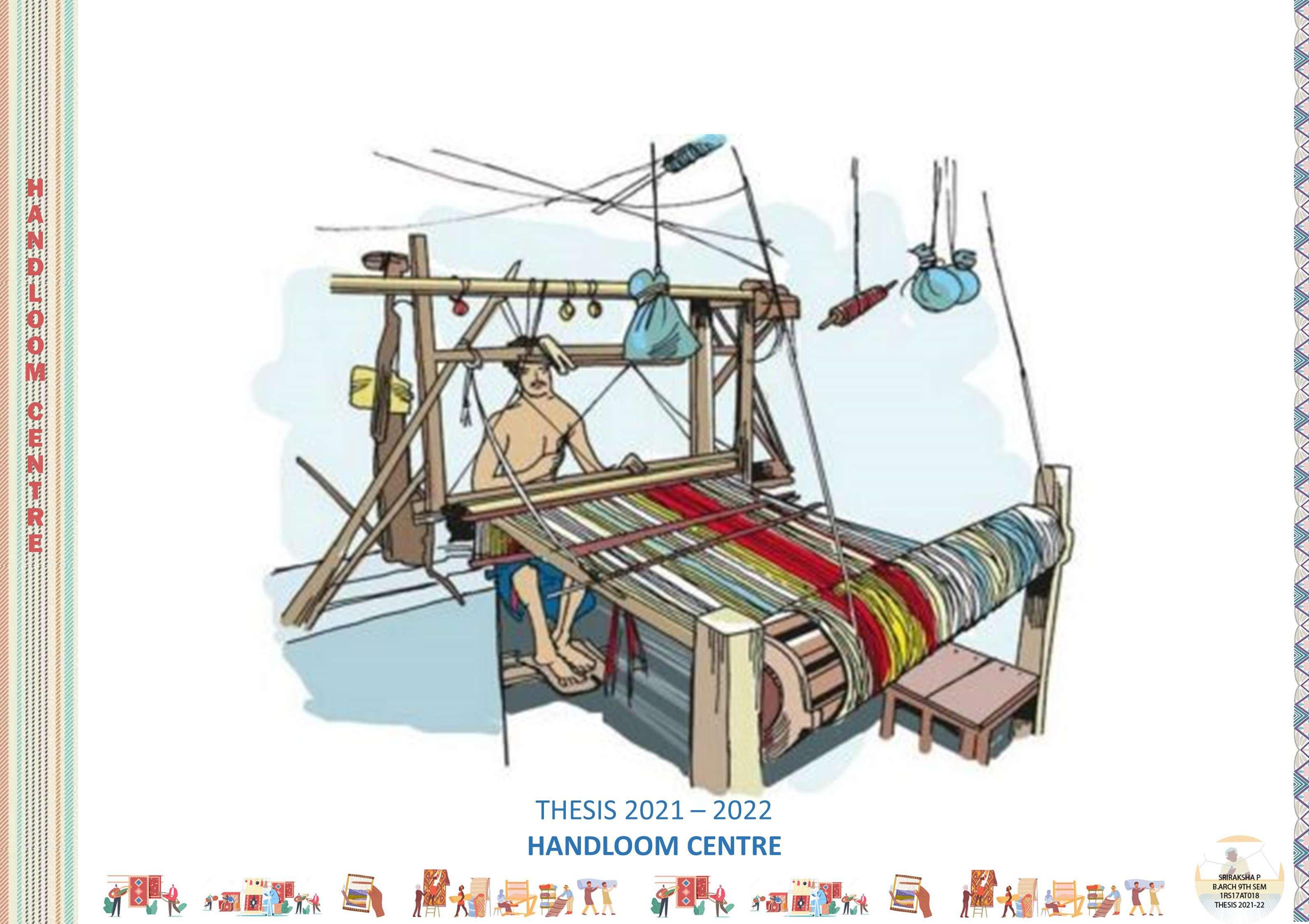
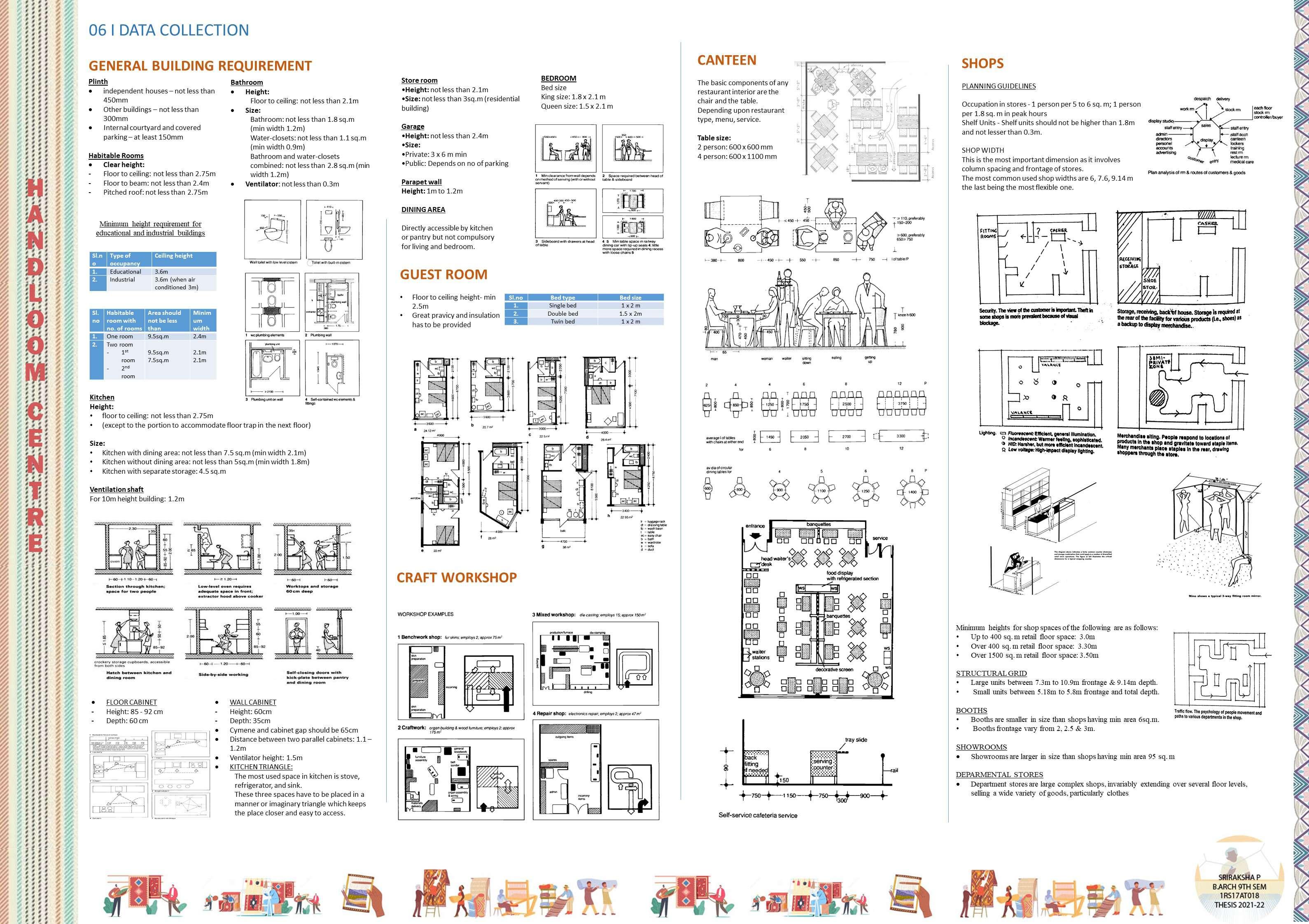
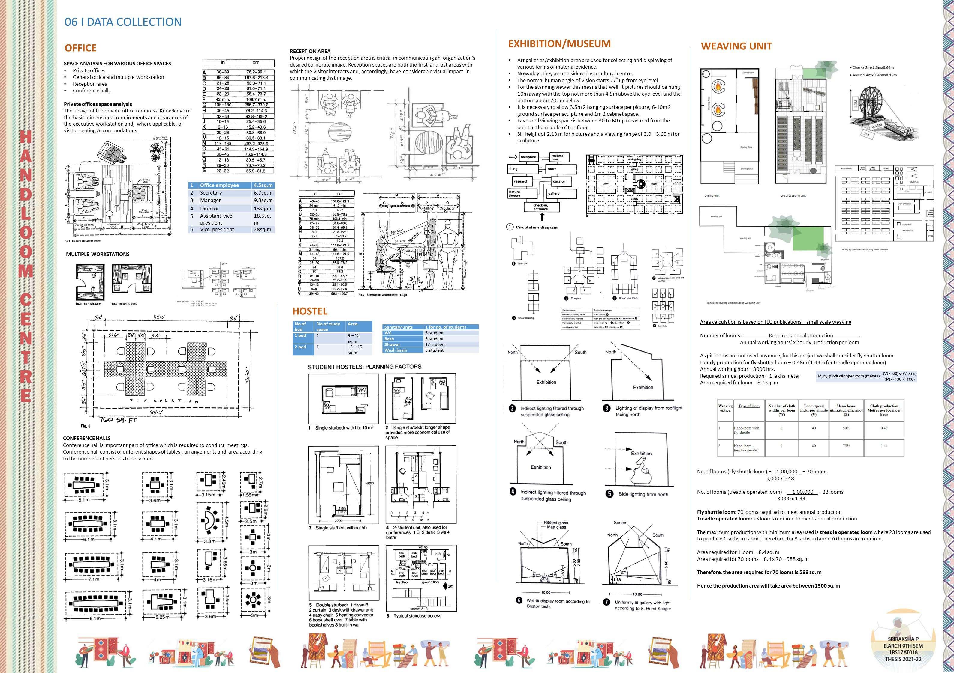
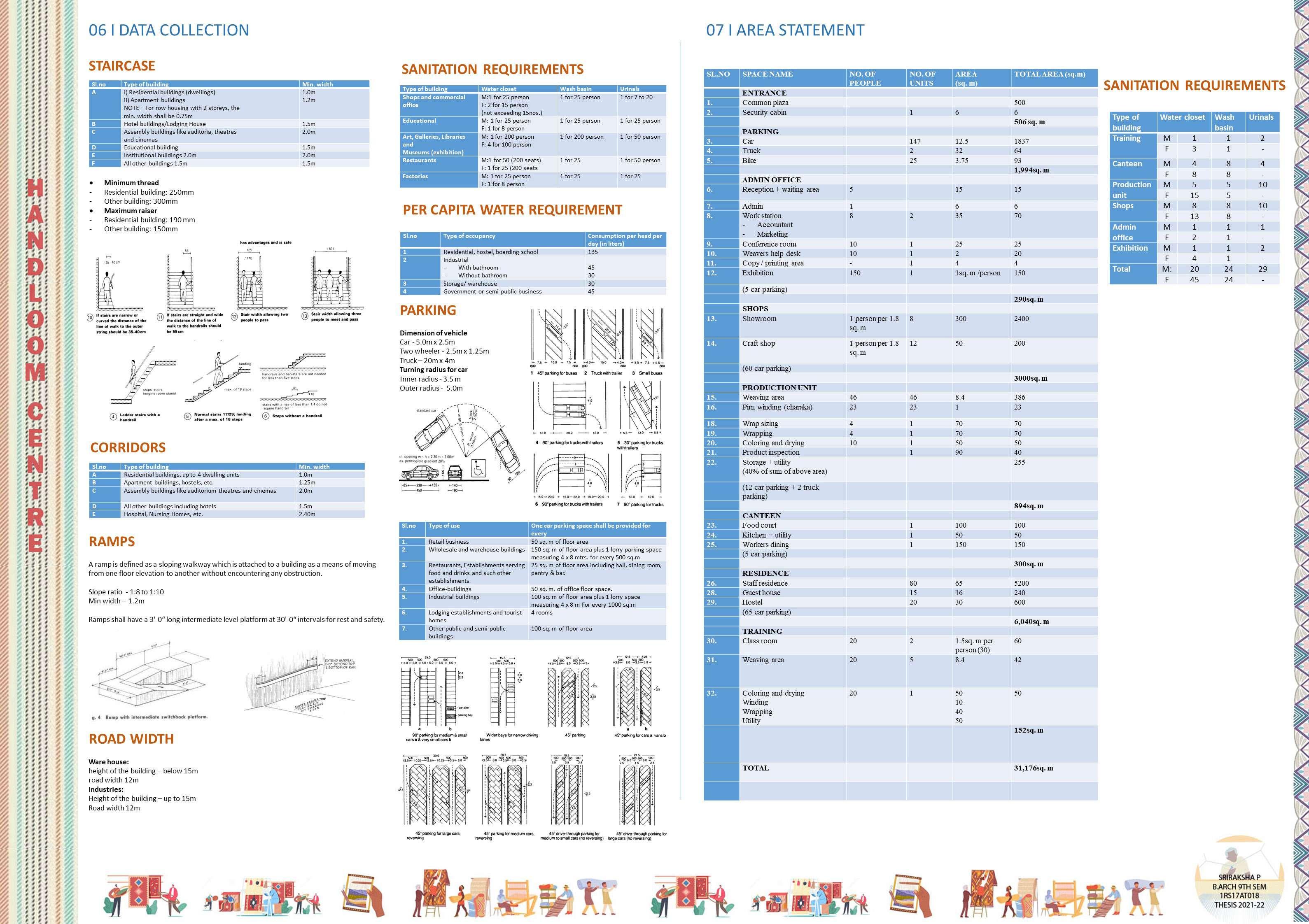
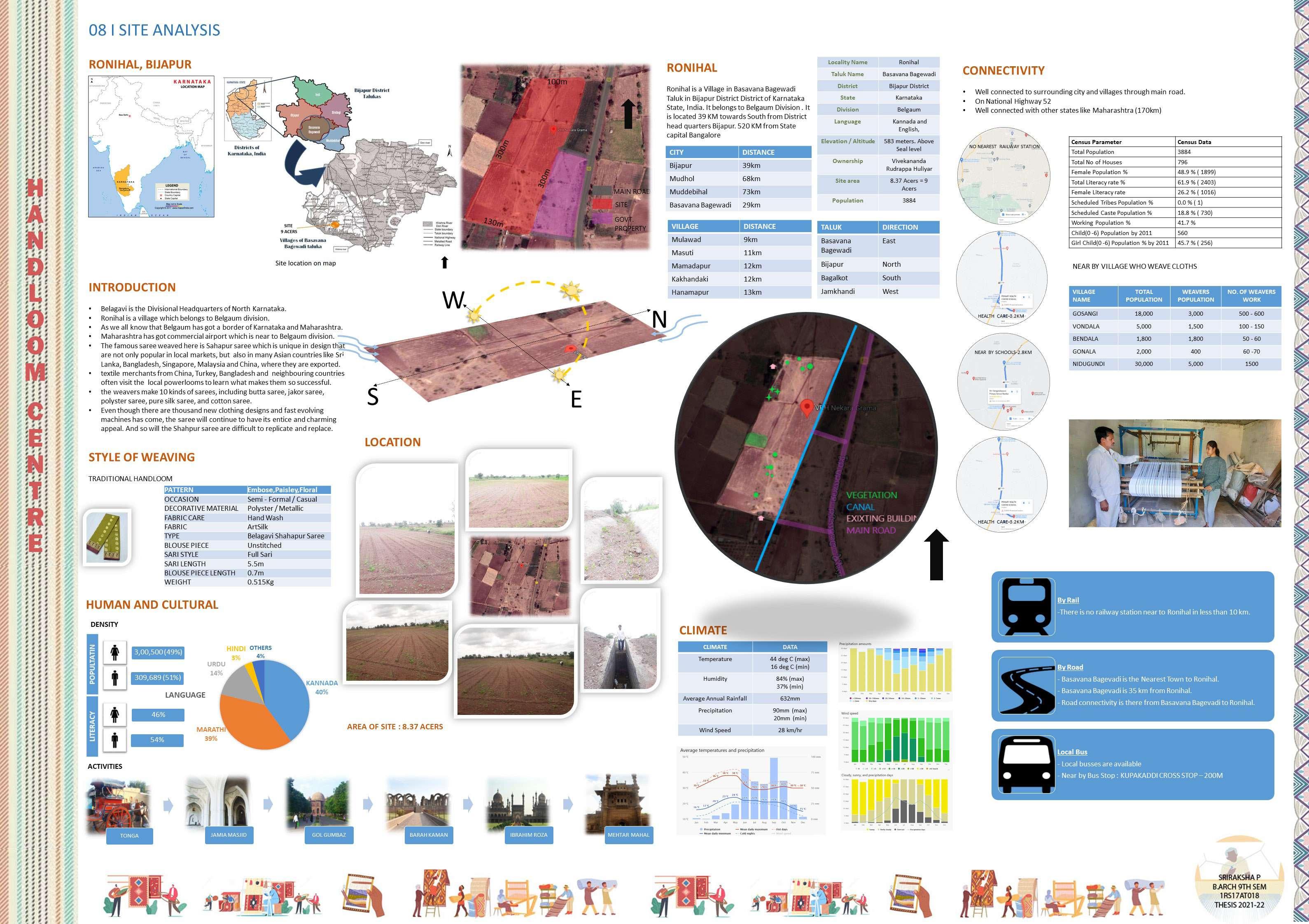
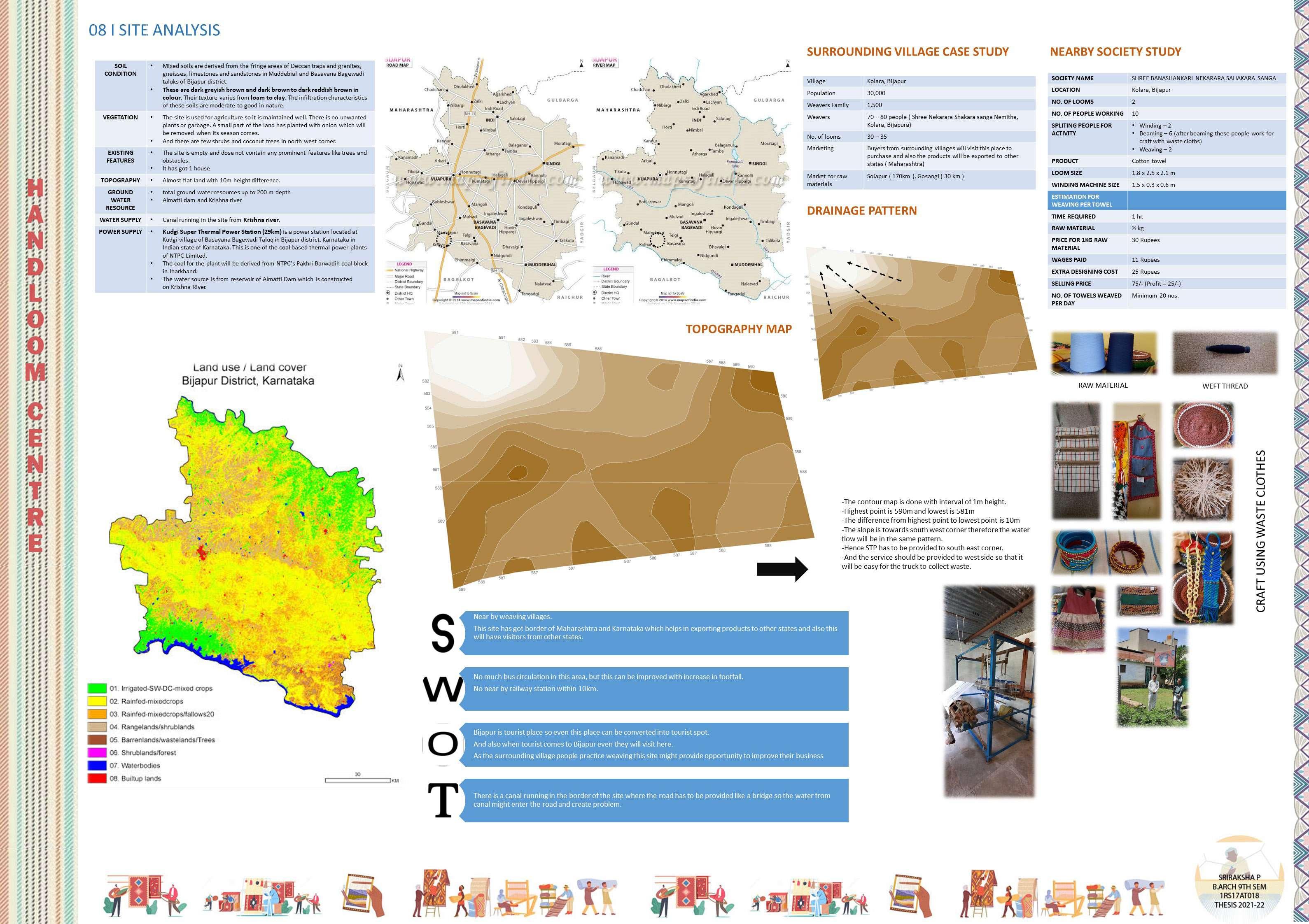
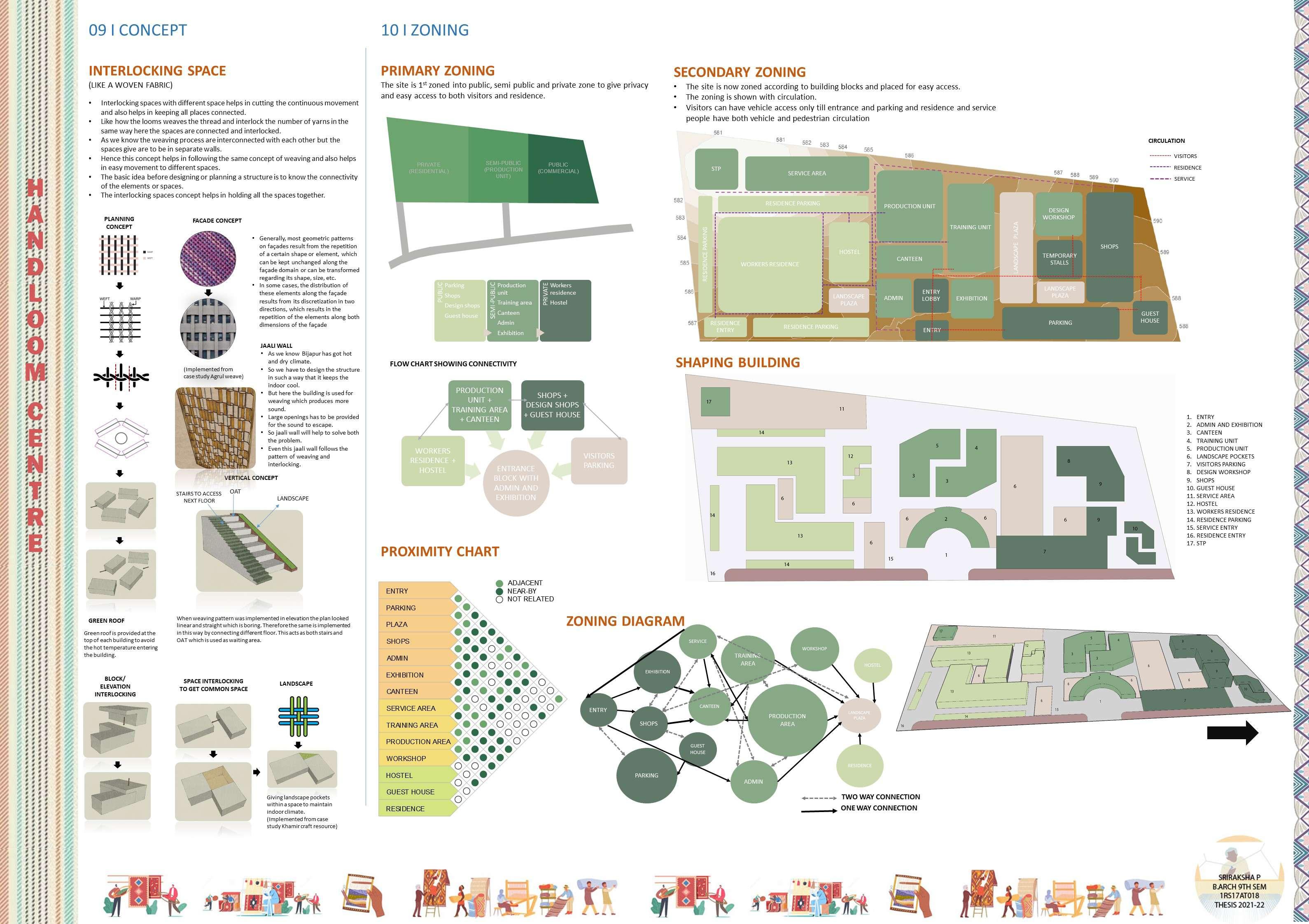
PORTFOLIO SRIRAKSHA P
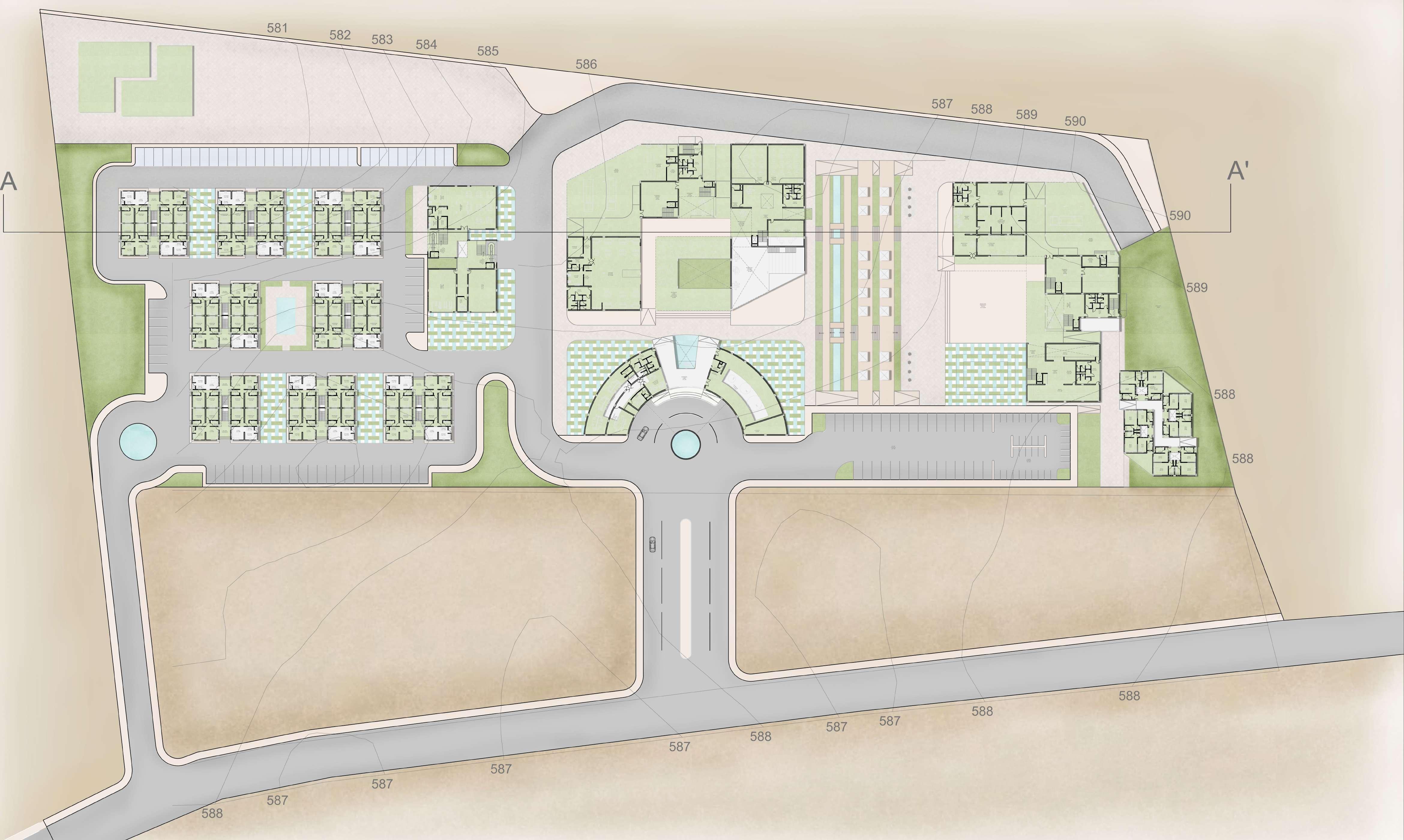

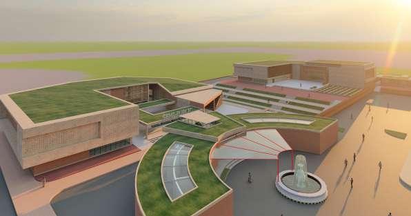
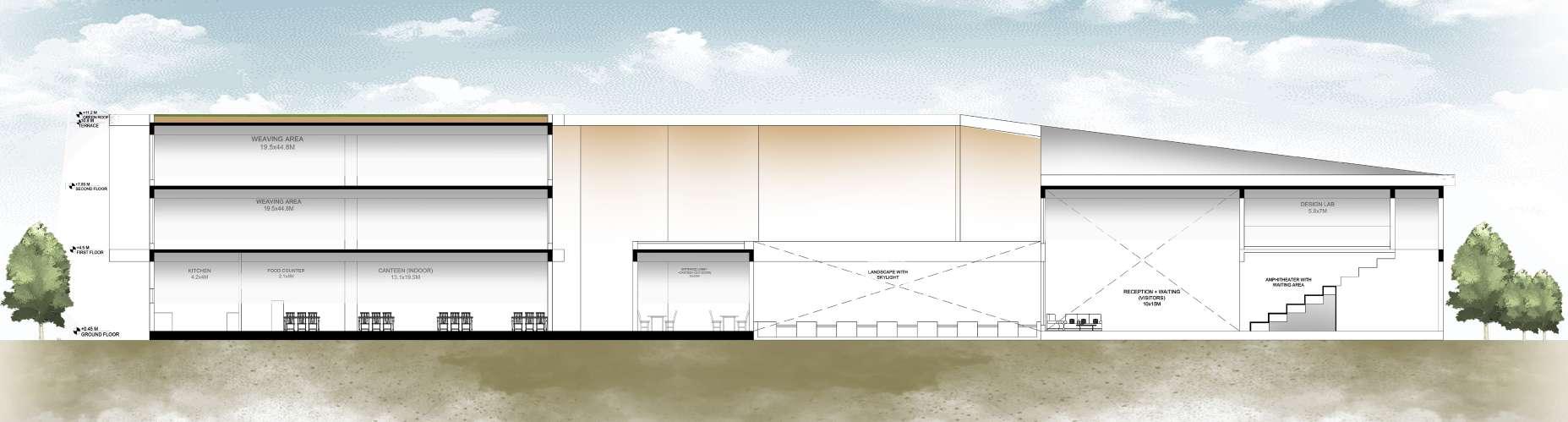
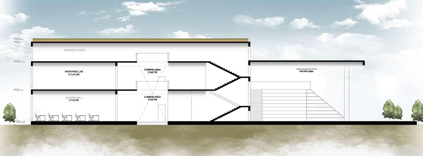
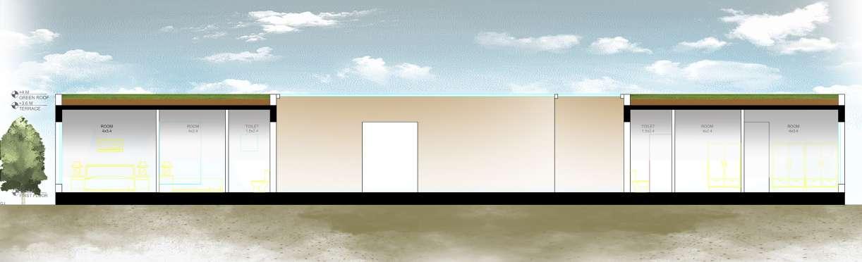
10 I DESIGN MASTER PLAN SECTION AT AA’
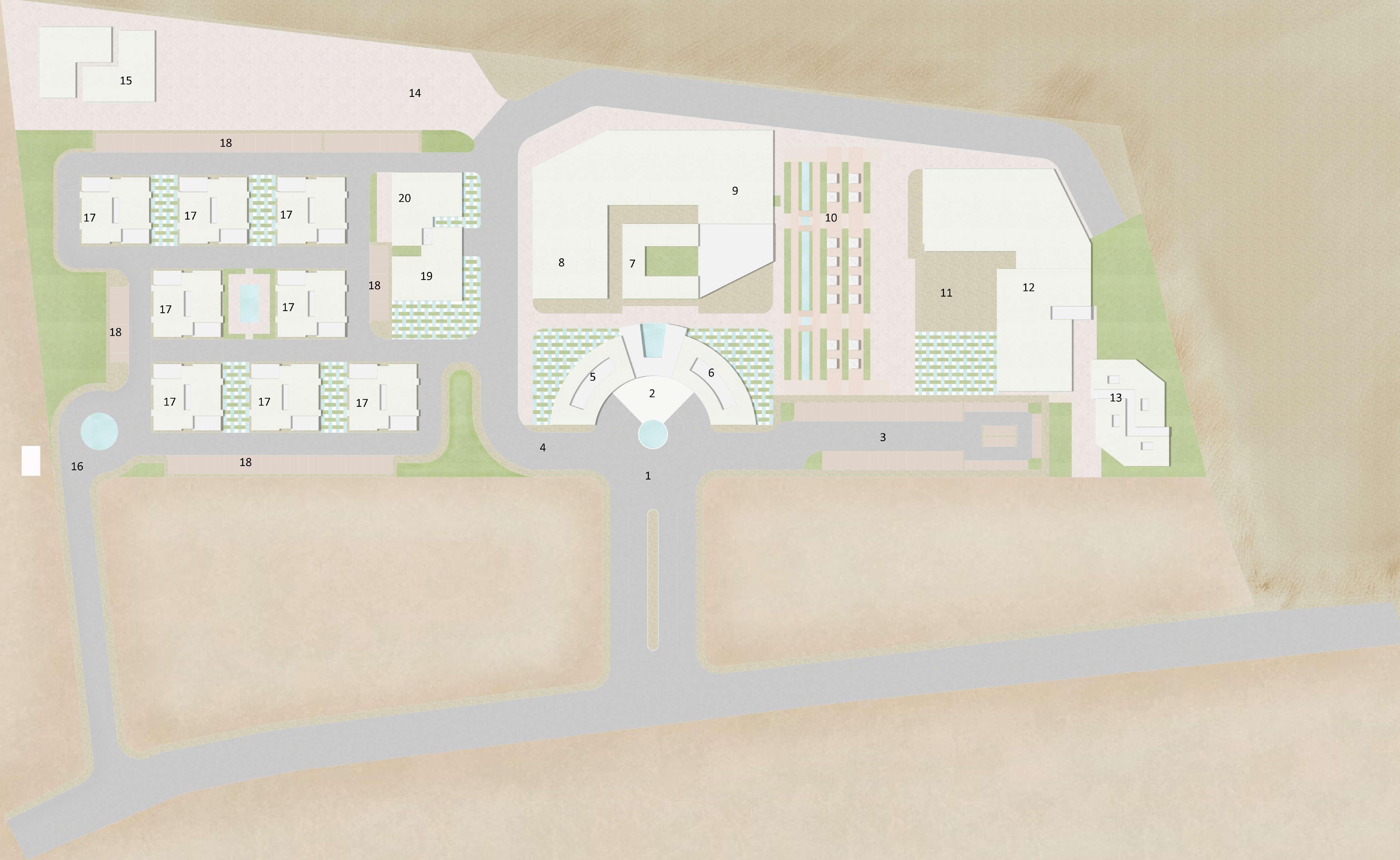
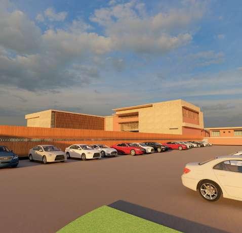
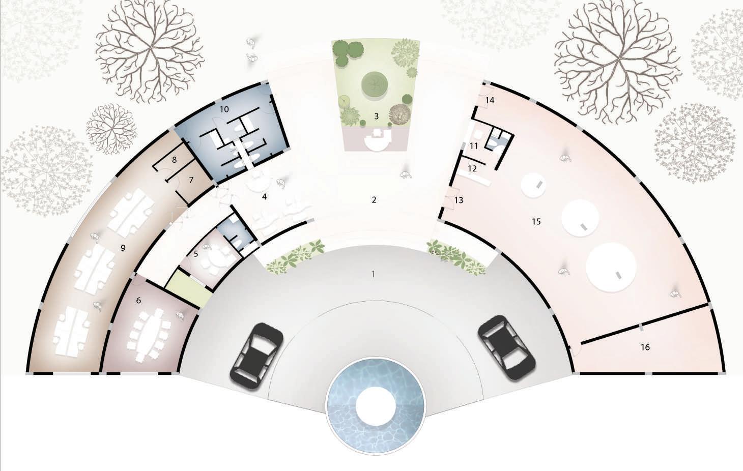
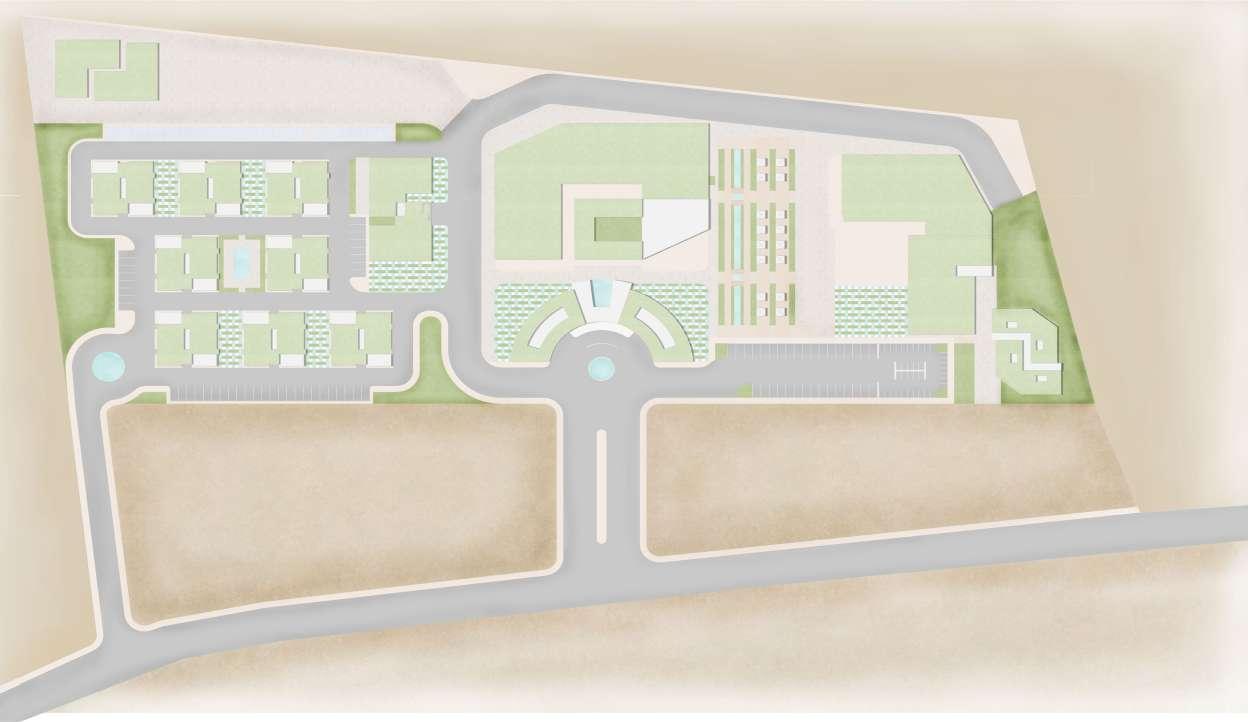
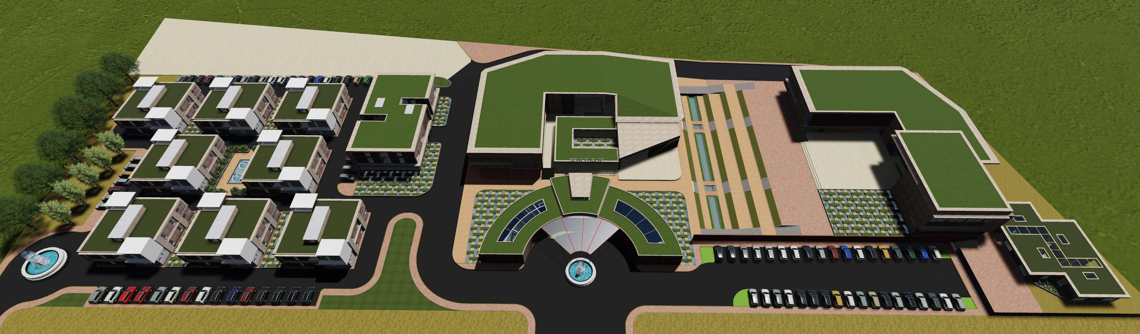
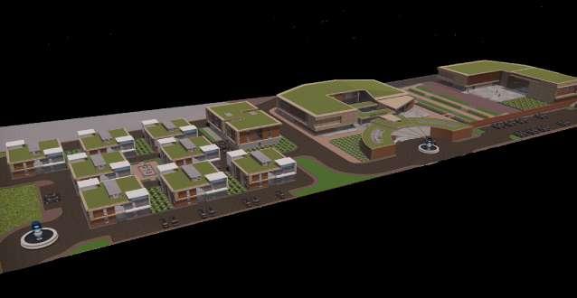
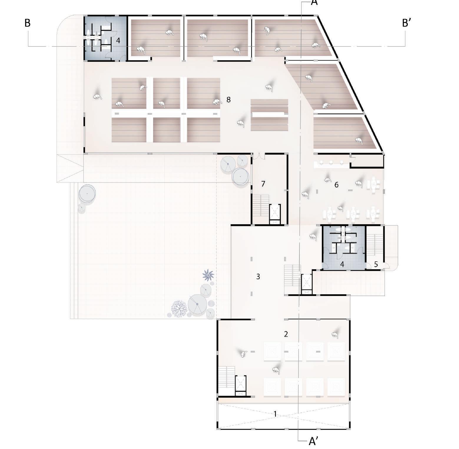
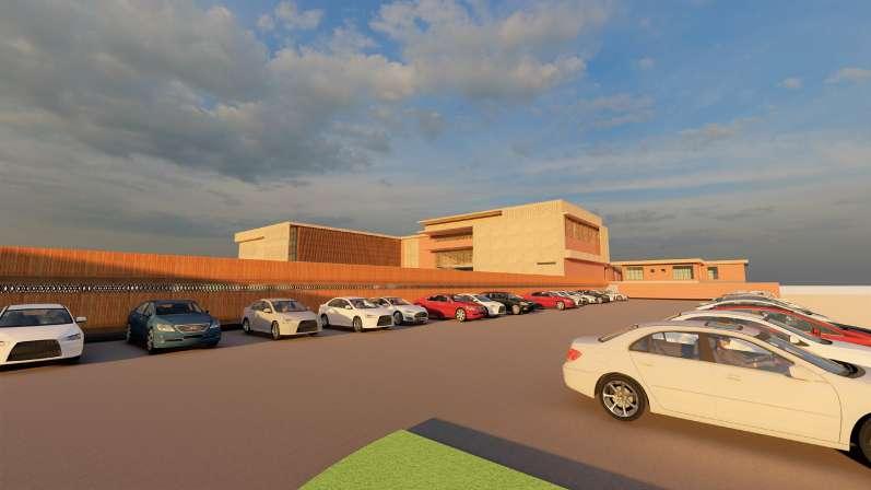
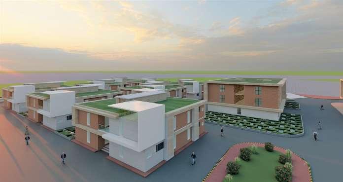
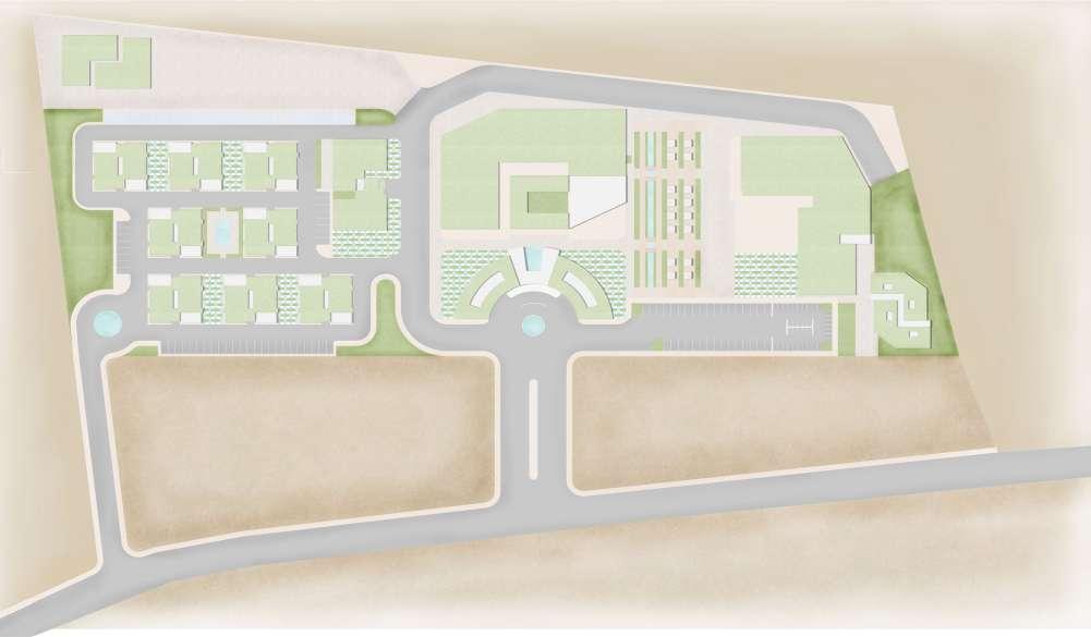
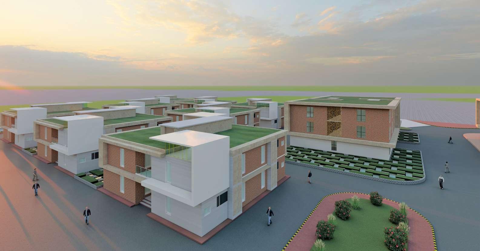
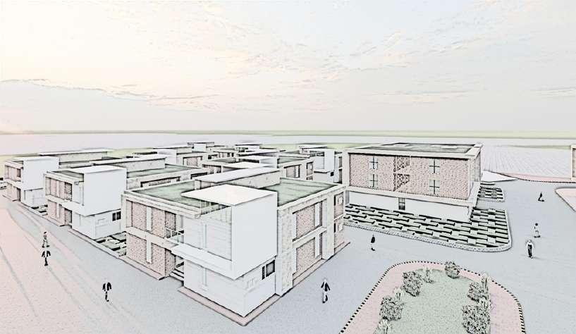
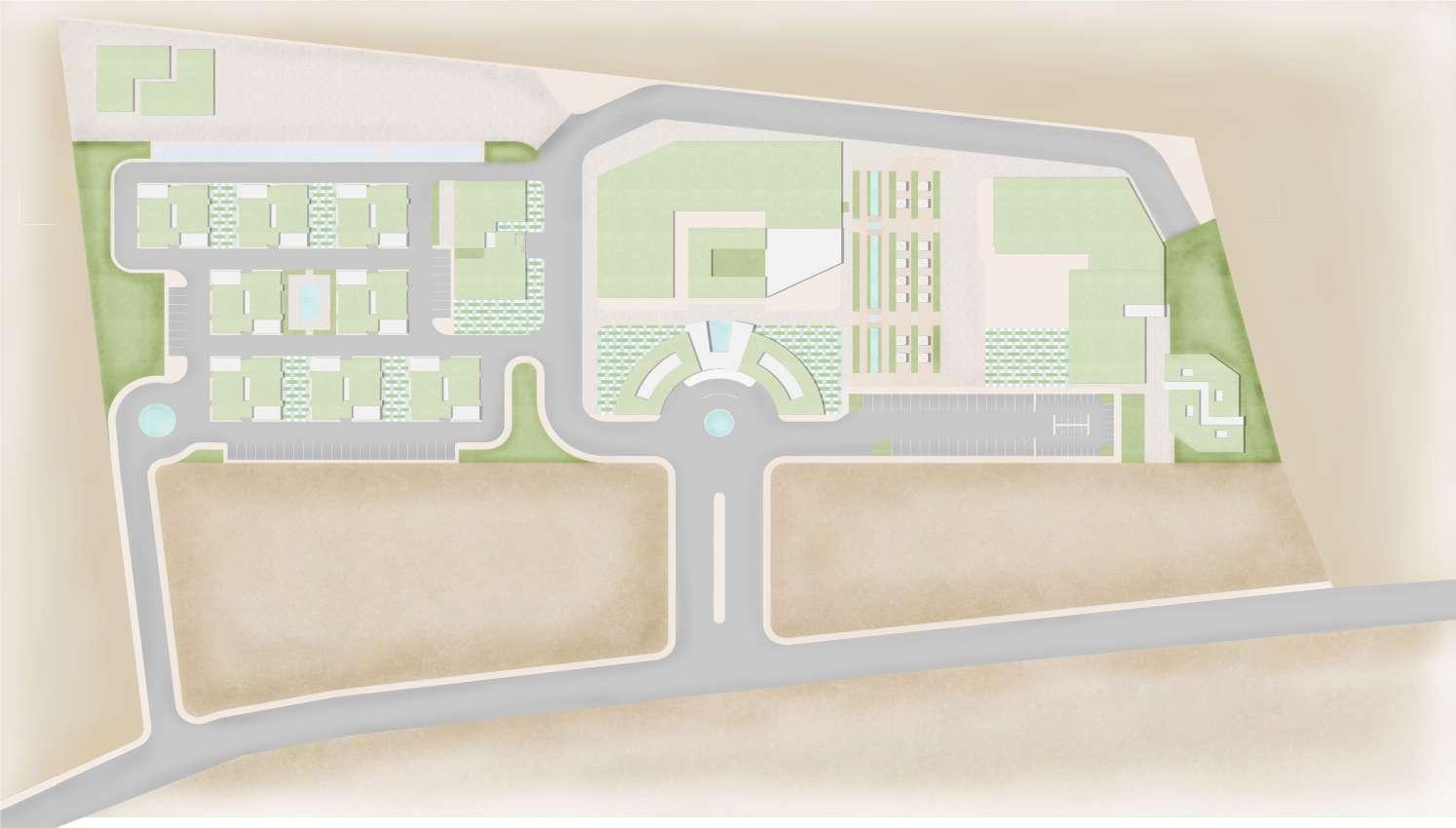
10 I DESIGN SITE PLAN 1. ENTRY 2. DROP OFF 3. VISITOR’S PARKING 4. SERVICE ENTRY 5. ADMIN OFFICE 6. EXHIBITION 7. CANTEEN 8. PRODUCTION UNIT 9. TRAINING UNIT 10. LANDSCAPE 11. TEMPORARY STALLS 12. SHOPS 13. GUEST HOUSE 14. SREVICES 15. STP 16. RESIDENCE ENTRY 17. WORKERS RESIDENCE 18. RESIDENCE PARKING 19. GIRLS HOSTEL 20 BOYS HOSTEL
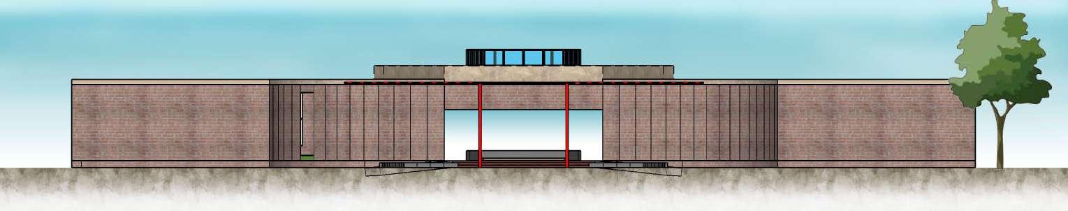

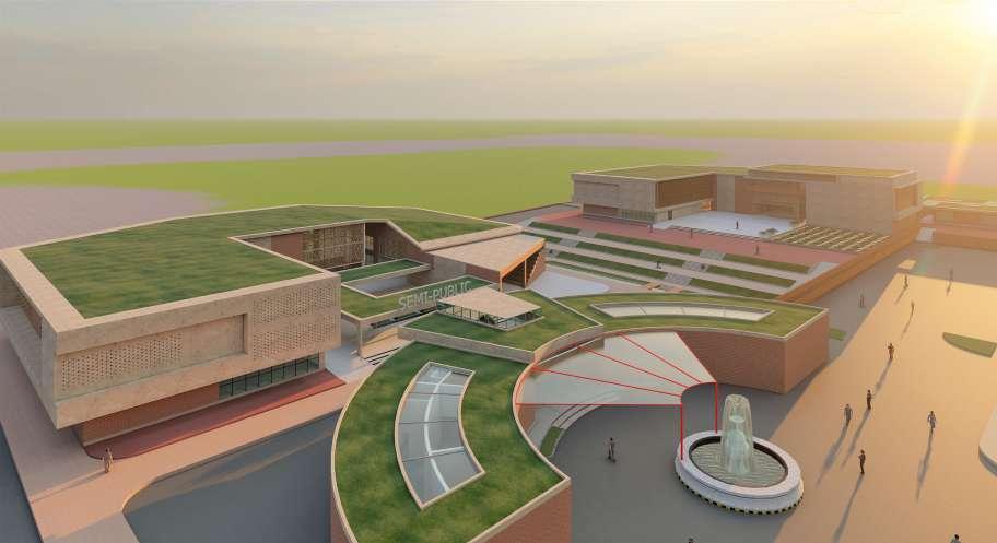

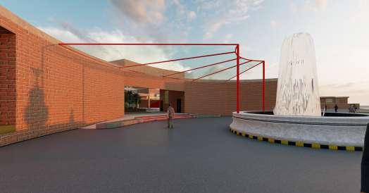
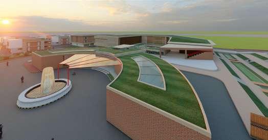
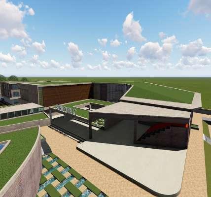
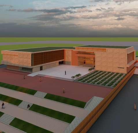
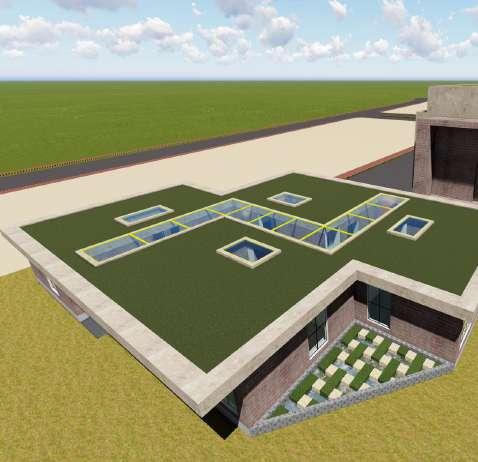
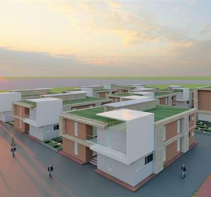
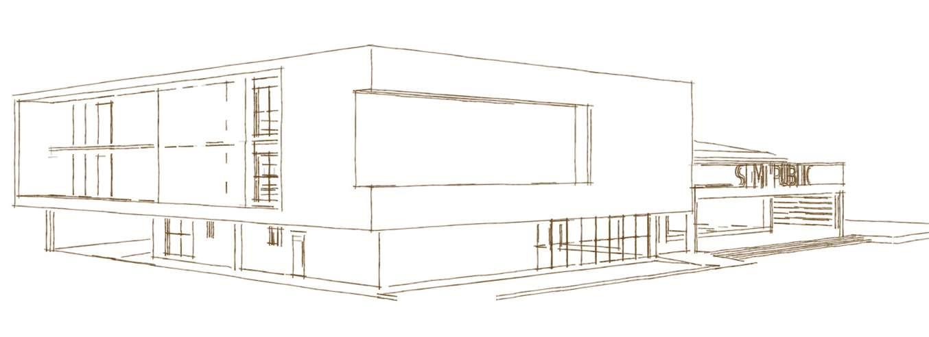
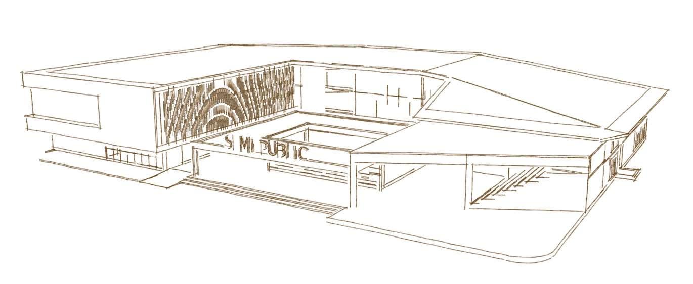
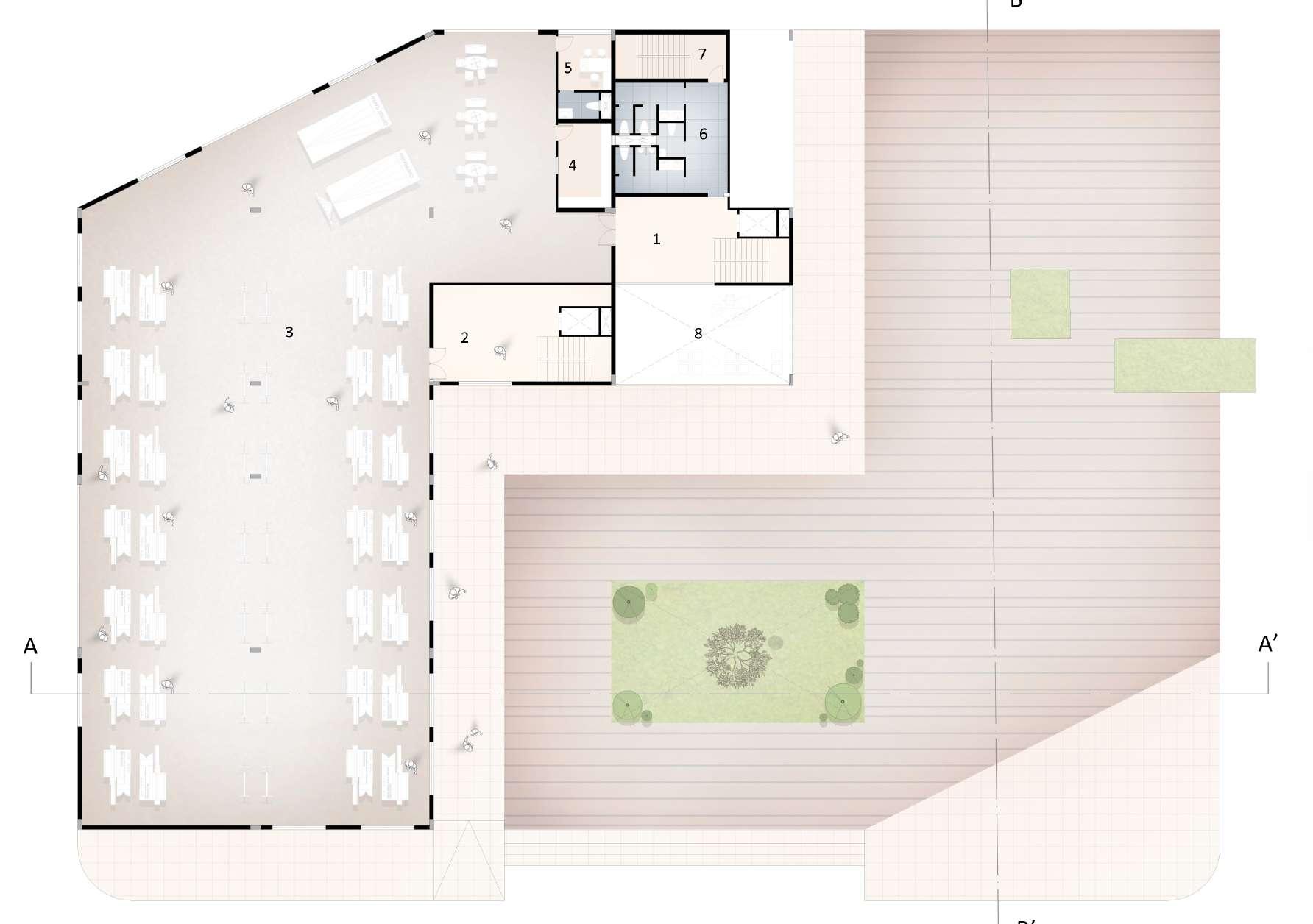
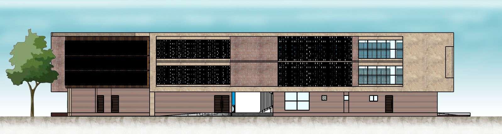
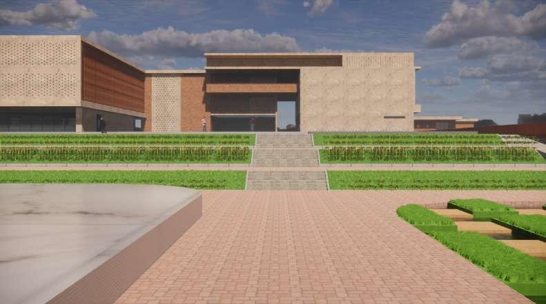
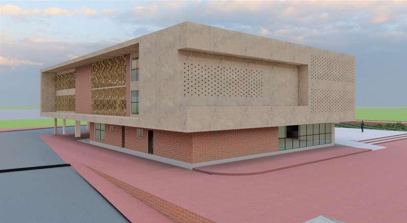
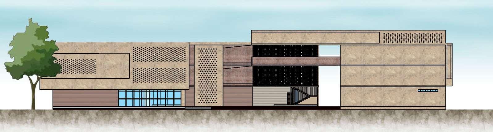
10 I DESIGN SITE 3D VIEW ADMIN OFFICE GROUND FLOOR PLAN 11.Ticket counter 3.5 x 3m 12. Ticket checking 13. Exhibition entry 14. Exhibition exit 15. Exhibition - 11.5 x 22m 16. Store room - 11.5 x 5m 6. Conference hall - 7 x 5.8m 7. Storage - 2.5 x 2.5m 8. Printing area 3 x 1.5m 9. Workstation 21.5 x 5.5m 10. Toilet - 6.2 x 6.2m 1. Entry drop off 2. Entrance lobby - 16 x 12m 3. Reception with landscape 4. Reception + waiting - 5.6 x 5.2m 5. Admin - 5 x 3.2m (toilet 1.6 x 2.6m) K E Y P L A N W E N S SCALE 1:250 1 2 3 4 5 14 13 12 11 10 A B C C B A 5.8 5.8 6 6.2 4.3 3.8 3.9 4.3 6.2 6 5.8 5.8 1 3 5 7 8 10 12 14 5.4 7 4.7 4.6 7 5.4 5.8 6.1 6.1 5.8 COLUMN, BEAM AND CENTRE LINE LAYOUT FRONT ELEVATION REAR ELEVATION WORKERS RESIDENCE STUDENT HOSTEL ADMIN BLOCK PRODUCTION UNIT CANTEEN TRAINING UNIT EXHIBITION COMMERCIAL SHOPS GUEST HOUSE TEMPORARY EXHIBITION LANDSCAPE ON CONTOUR
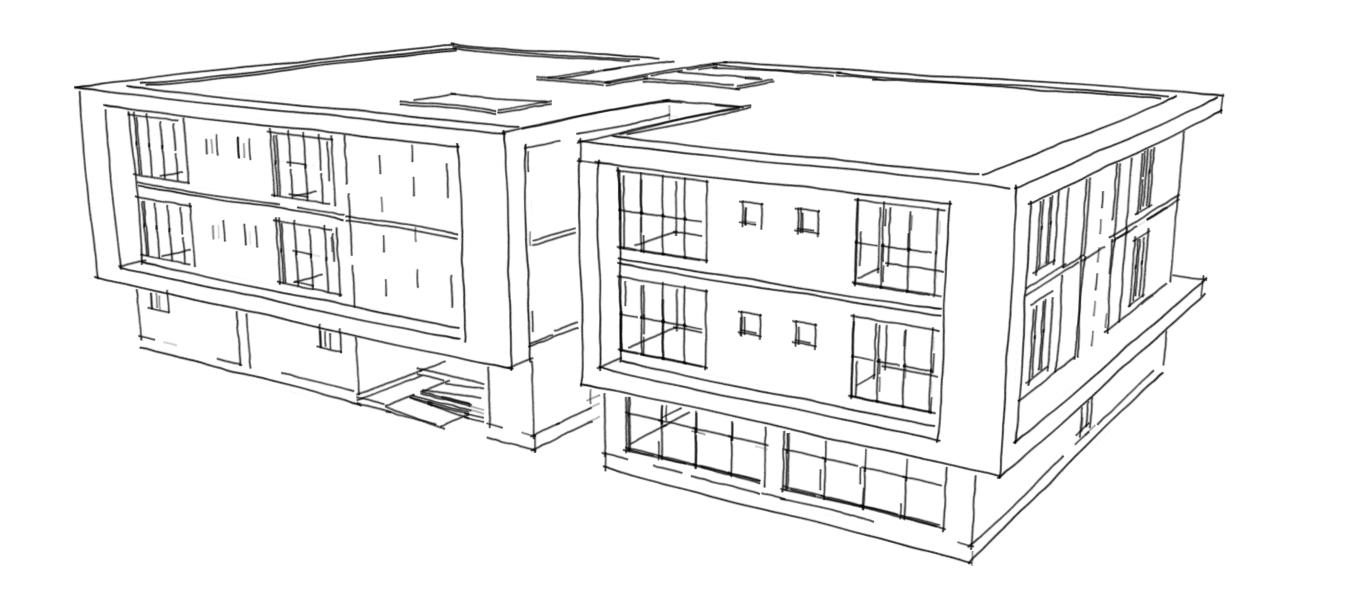
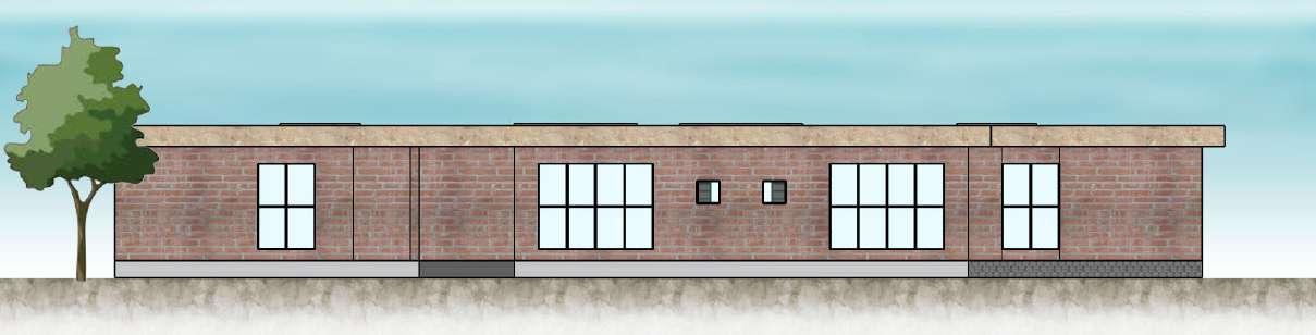
PRODUCTION AND TRAINING BLOCK
LEGEND
GROUND FLOOR
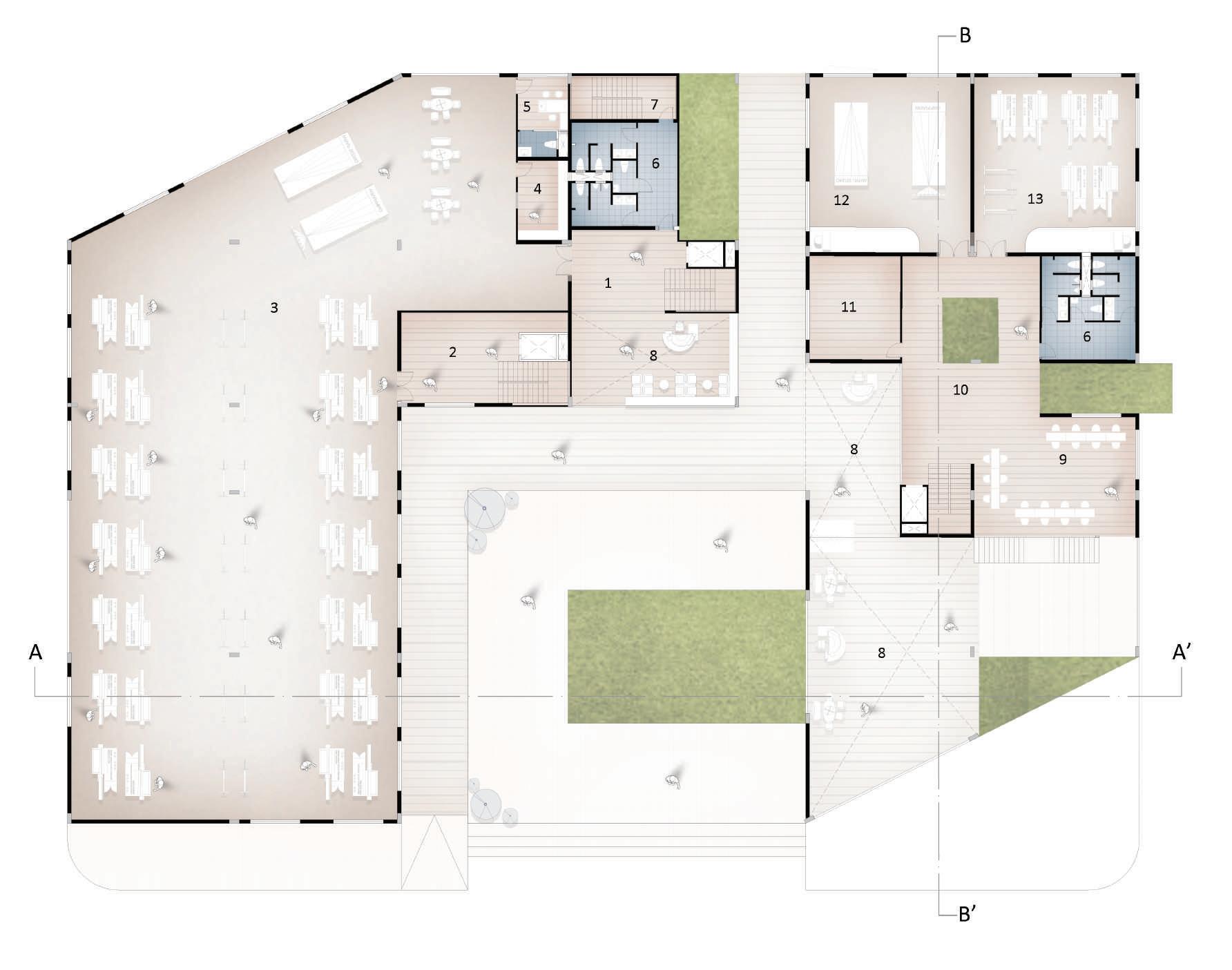
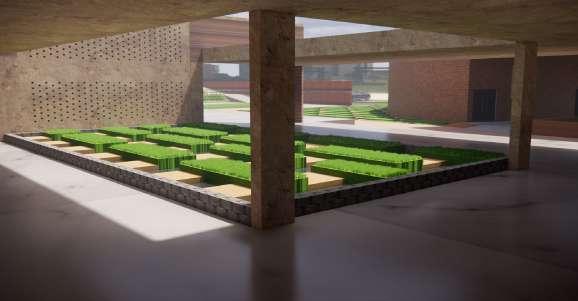
Production and training unit are placed next to eachother so that the students can have interaction with weavers and get some practical knowledge.
Coloring and drying is common area for both workers and students. And this cannot be provided inside the building so the coloring area is placed in semi closed area in ground floor. For drying colored yarns shaded area with nice air flow is provided.

Truck parking is provided in such a way that it is easy to load and unload goods even during harsh sun light and rain. The truck can directly come and park in ground floor with shaded roof.
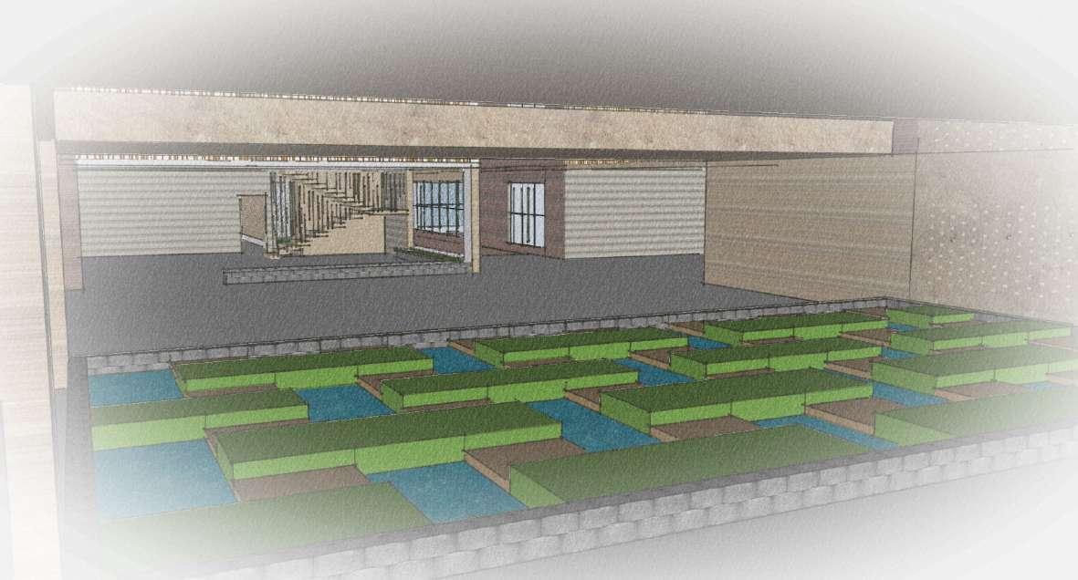
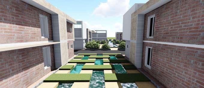
Landscape pockets are provided which is like a space within a space. Providing these kind of landscape with water body helps to keep the surrounding cool.
Weaving area will have more noise pollution hence more openings are provided so the the noise can escape.
FIRST

GROUND FLOOR PLAN SECOND FLOOR PLAN
FLOOR
PLAN
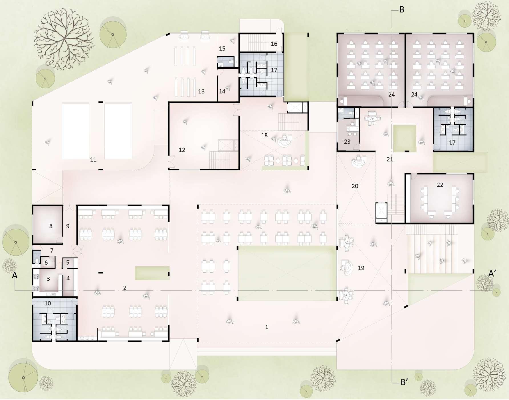
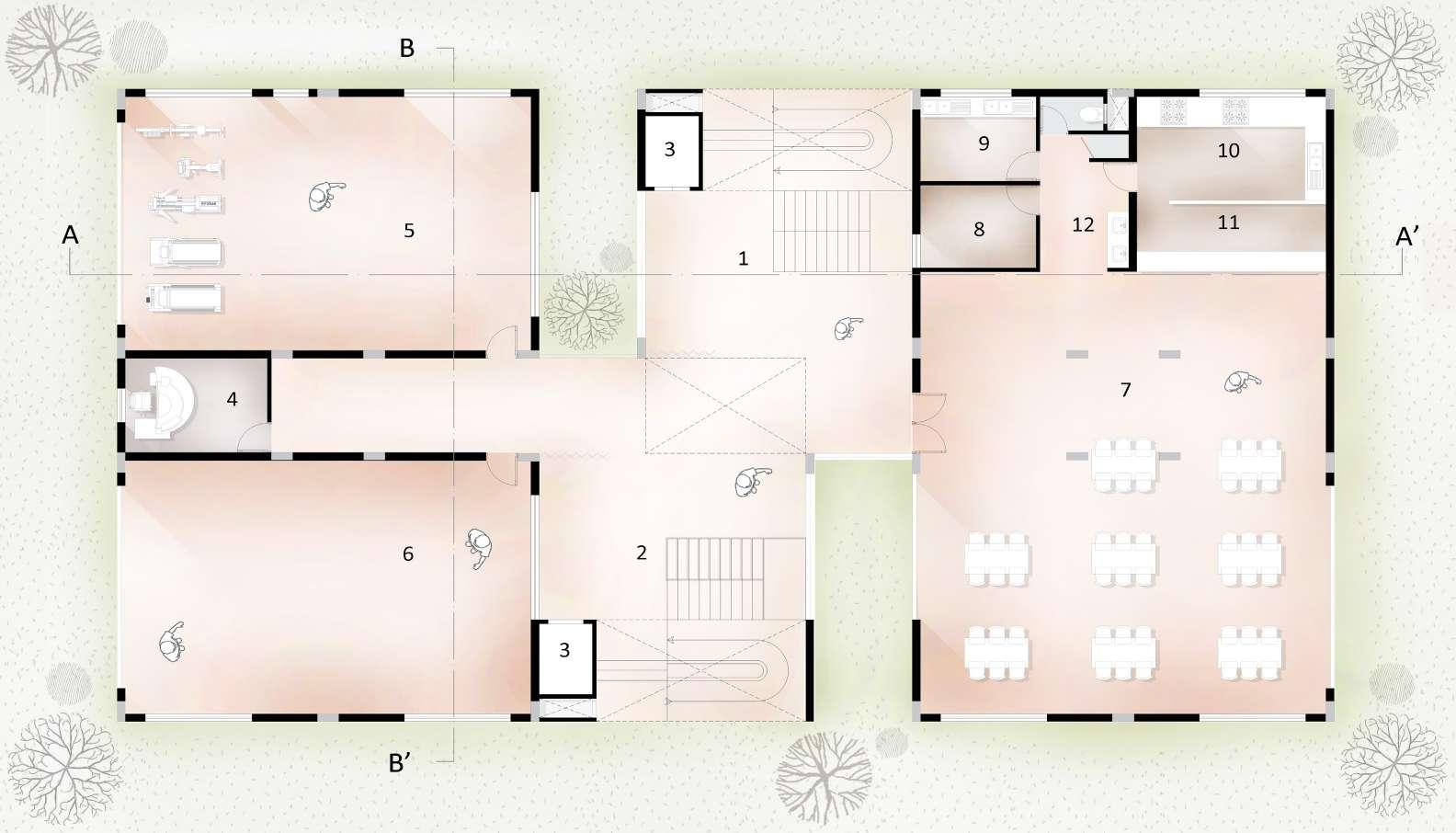
1. Canteen (outdoor) - 20 x 20m 2. Canteen (indoor) - 13.1 x 19.5m 3. Kitchen - 4.2 x 4m 4. Food counter - 2.1 x 4m 5. Billing 2.1 x 1.4m 6. Washing - 1.6 x 2m 7. Service area- 5.2 x 1.6m 8. Store room 4.2 x 5.4m 9. Service corridor - 2 x 5.6m 10. Toilet - 6.2 x 6.2m 11. Truck parking (loading/Unloading) - 20 x 15m 12. Storage + Service area - 10 x 9.5m 13. Coloring + drying - 6.9 x 9.9m 14. Yarn storage 3 x 4.8m 15. Washing - 3 x 3.3m 16. Fire escape - 6.2 x 2.5m 17. Toilet - 6.2 x 6.2m 18. Production unit entrance - 10 x 10.6m 19. Reception + Waiting (visitors) - 10 x 15m 20. Reception + Waiting (students) - 5.7 x 7.6m 21. Circulation area - 8.4 x 9.4m 22. Staff room 5.6 x 7m 23. Principle office - 4.6 x 5.4m 24. Lecture hall - 9.7 x 10.5m FIRST FLOOR 1. Lobby - 6.3 x 4.8m 2. Storage + service area - 10 x 5.4m 3. Weaving area - 19.5 x 44.8m 4. Pantry 3 x 4.8m 5. Office - 3 x 3.2m 6. Toilet 6.2 x 6.2m 7. Fire escape - 6.2 x 2.5m 8. Double heigth 9. Design lab 5.6 x 7m 10. Circulation area - 8.3 x 9.7m 11. Store room - 5.5 x 6.2m 12. Wrapping lab - 9.7 x 10.5m 13. Weaving lab - 9.7 x 10.5m 1. Lobby - 6.3 x 4.8m 2. Storage + service area - 10 x 5.4m 3. Weaving area - 19.5 x 44.8m 4. Pantry - 3 x 4.8m 5. Office - 3 x 3.2m 6. Toilet - 6.2 x 6.2m 7. Fire escape 6.2 x 2.5m 8. Double heigth 3D VIEW SHOWING PRODUCTION AND TRAINING UNIT 10 I DESIGN
W E N S KEY PLAN SCALE 1:250 PRODUCTION UNIT AND TRAINING UNIT
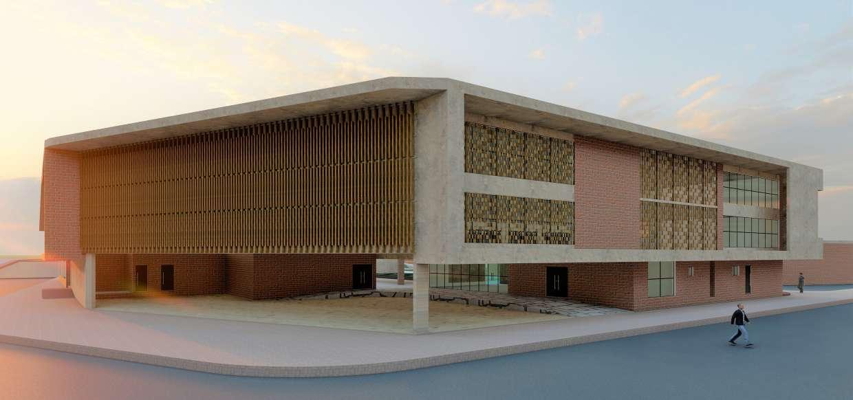
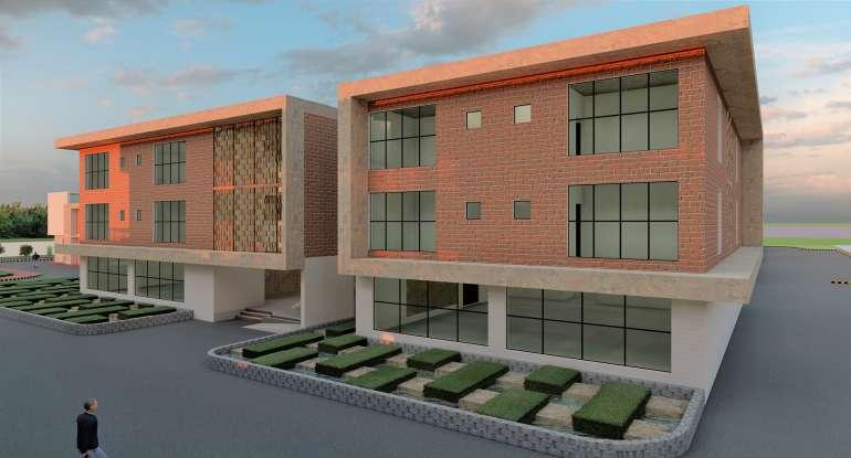
PRODUCTION AND TRAINING BLOCK
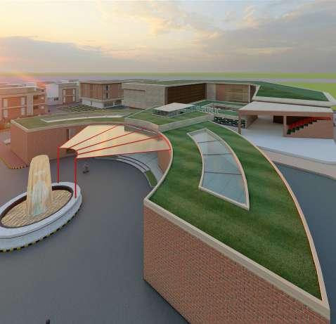
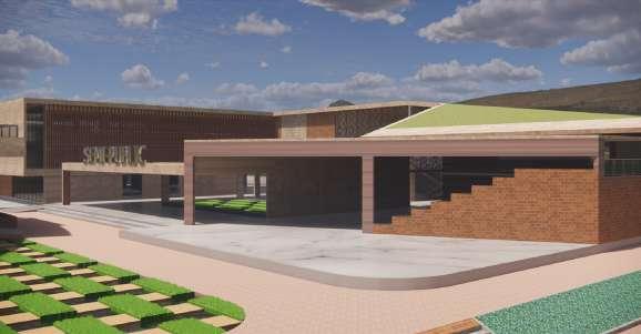
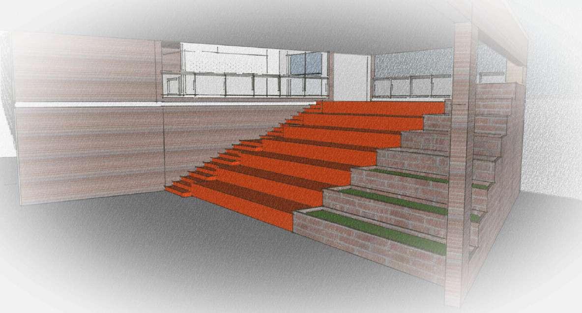
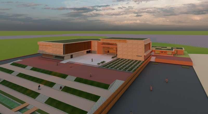
LANDSCAPE AND WATER BODY NEAR OUT-DOOR CANTEEN OAT WHICH ACTS AS BOTH SEATING AND STAIRS
PRODUCTION UNIT TRAINING AREA COLUMN, BEAM AND CENTRE LINE LAYOUT
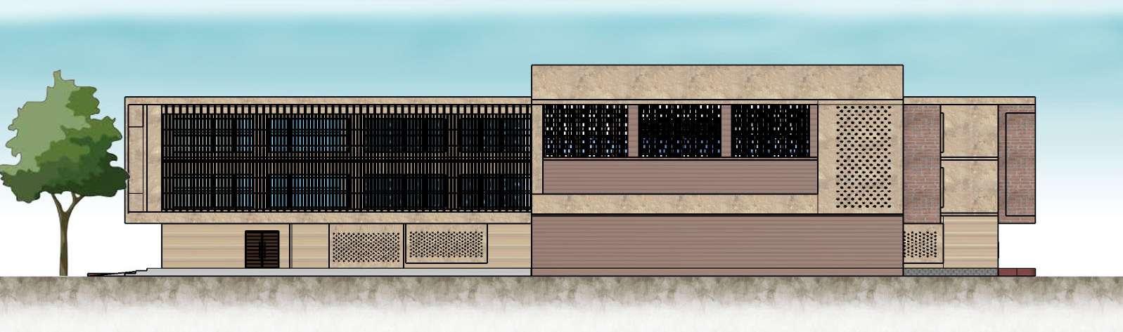
ELEVATION
ELEVATION
10 I DESIGN
SECTION AT AA’
1 2 3 4 A B C D E F 10.1 9.7 10.2 10 10 9.8 5.2 9.8 10 1 4 B C D E F G H A D H 6 14.3 9.9 9.9 10.7 6.4 7.9 19.8 6 3.8 4 6
SECTION AT BB’
FRONT
SIDE
W E N S SCALE 1:250 3D VIEWS
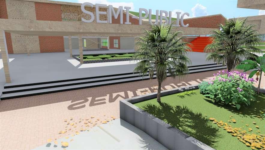
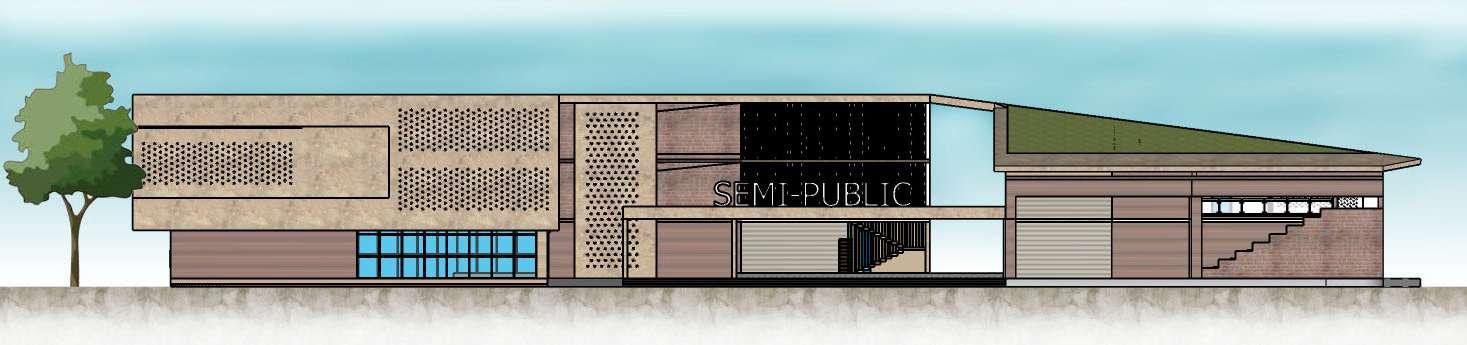
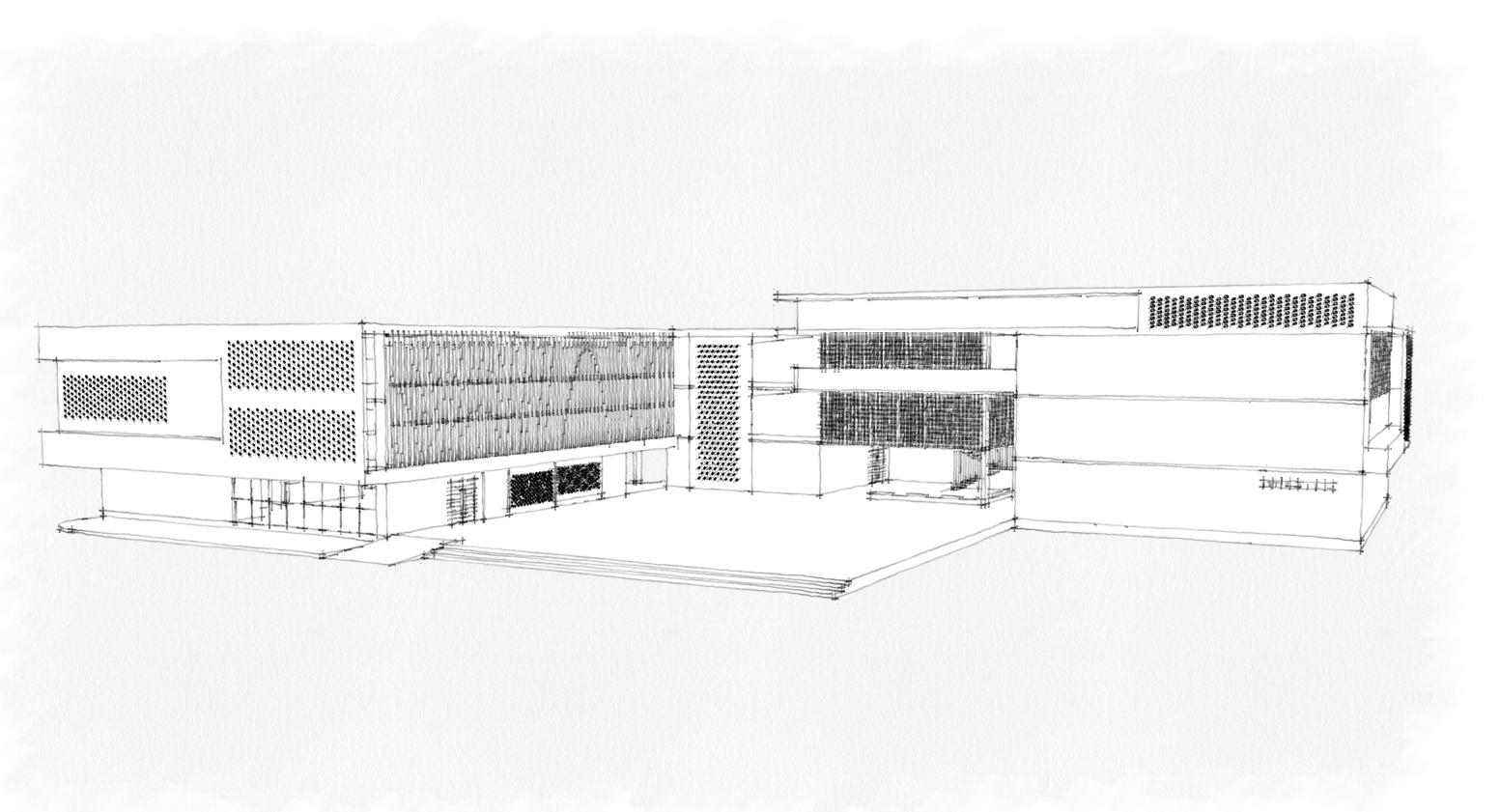
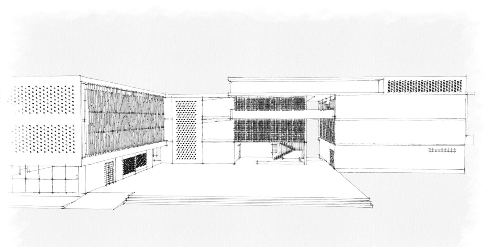
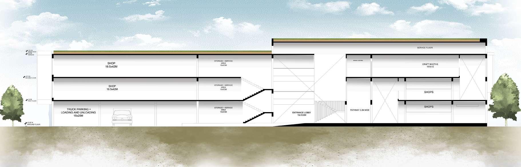
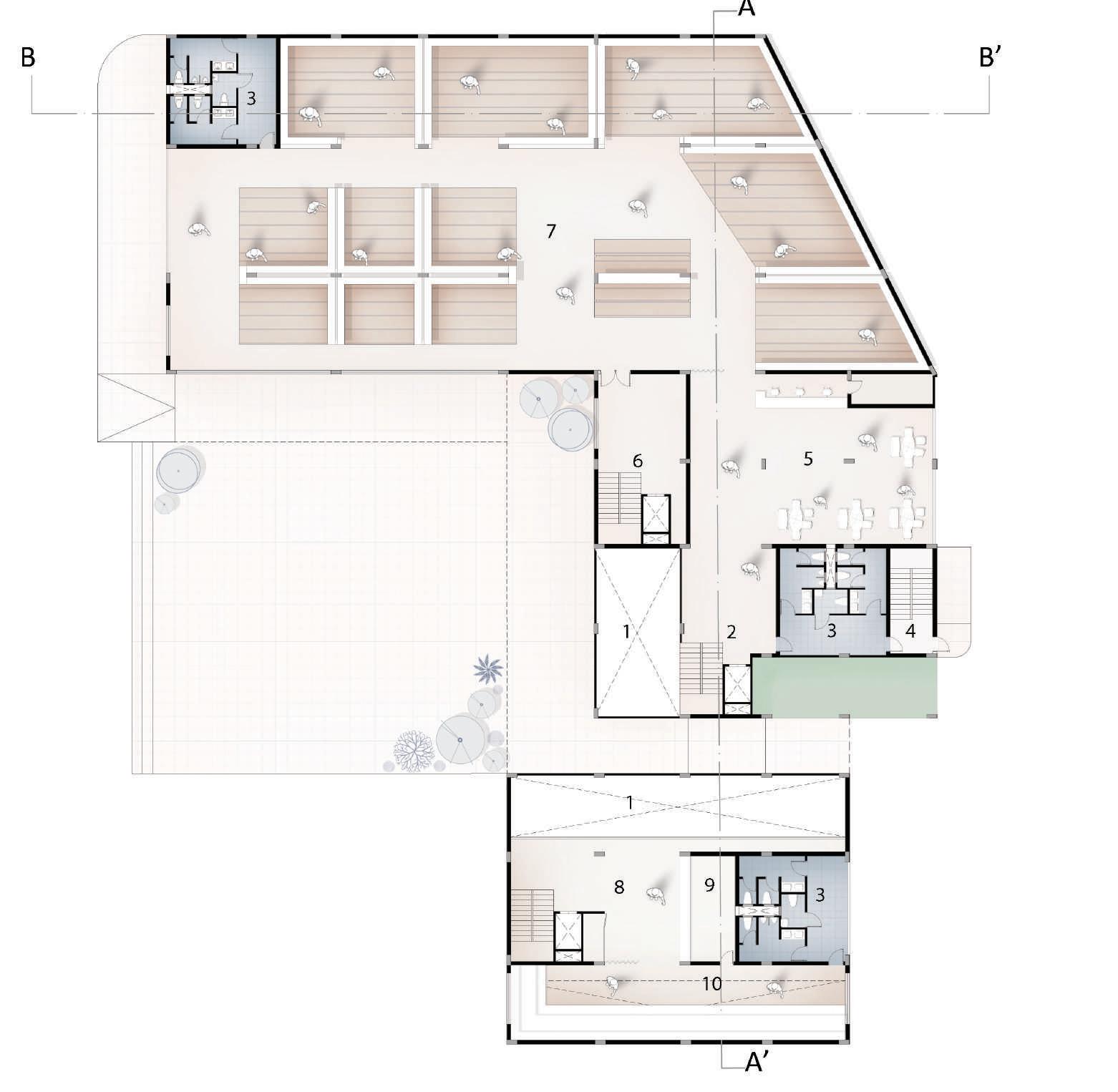
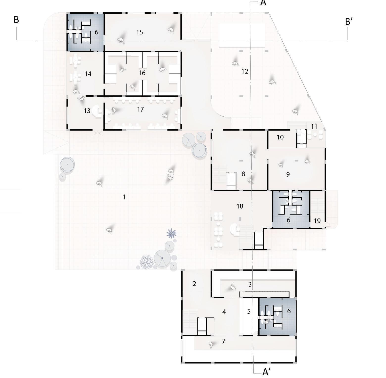
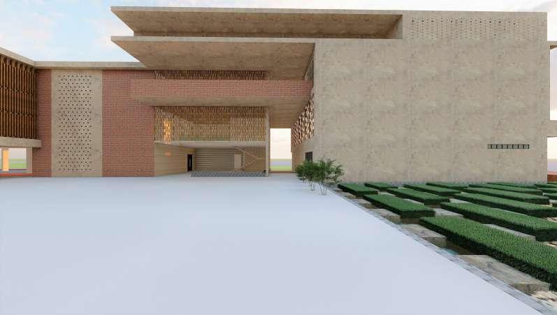
COMMERCIAL AREA (SHOPS)
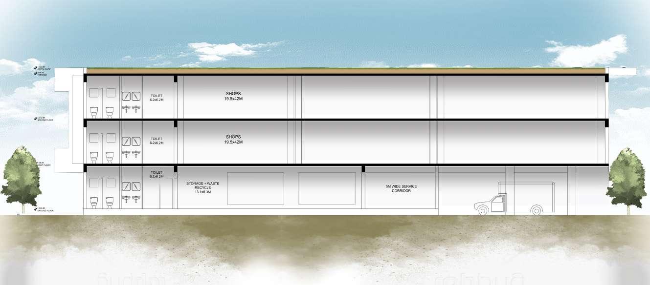

GROUND FLOOR PLAN FIRST FLOOR PLAN SECOND FLOOR PLAN 10 I DESIGN
13. Reception + Billing - 6.2 x 5.5m 14. Waiting area - 6.2 x 7.3m 15. Storage + waste recycle 13.1 x 6.3m 16. Tassels + Embroidery 13.1 x 7.3m 17. Cutting and stitching - 13.1 x 5.5m 18. Shop waiting area - 10 x 10.6m 19. Fire escape 2.5 x 6.2m 7. Shop 2 19.5 x 4.4m 8. Storage + Service area - 10 x 9.5m 9. Storage for ready products - 9.8 x 7m 10. Goods incharge office - 4.8 x 3m 11. Drivers waiting area - 3.3 x 4.3m 12. Truck parking - 15 x 20m 1. Space for temporary shops - 25.8 x 23.5m 2. Entry - 4.9 x 4.6m 3. Shop 1 - 14.4 x 4.4m 4. Circulation area - 9.9 x 6.2m 5. Billing counter 3.2 x 6.2m 6. Toilet - 6.2 x 6.2m 6. Service area 10 x 9.5m 7. Showroom - 19.5 x 42m 8. Circulation area - 9.9 x 6.2m 9. Billing counter - 3.2 x 6.2m 10. Shop - 19.5 x 4.4m 1. Double height 2. Lobby - 5.5 x 6.2m 3. Toilet - 6.2 x 6.2m 4. Fire escape - 2.5 x 6.2m 5. Billing + waiting - 14.1 x 10m 5. Fire escape 2.5 x 6.2m 6. Billing + waiting - 14.1 x 10m 7. Service area - 10 x 9.5m 8. Showroom - 19.5 x 42m 1. Double height 2. Space for craft booths - 19.6 x 12m 3. Connecting corridor - 13.5 x 13.3m 4. Toilet - 6.2 x 6.2m K E Y P L A N SCALE 1:250 SECTION AT AA’ SECTION AT BB’ W E N S
COMMERCIAL AREA (SHOPS)
COLUMN, BEAM AND CENTRE LINE LAYOUT

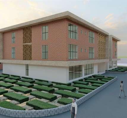
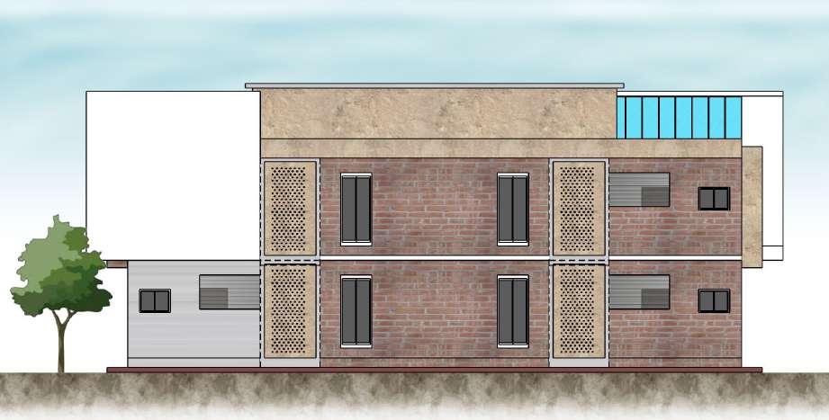
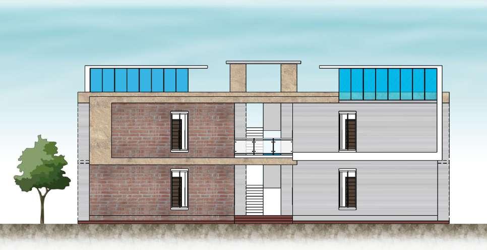
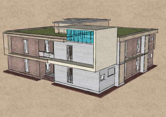
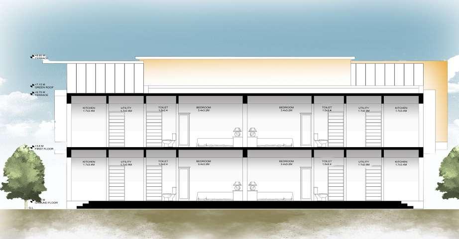
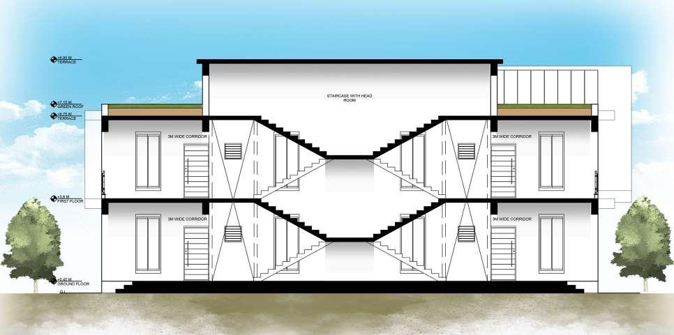
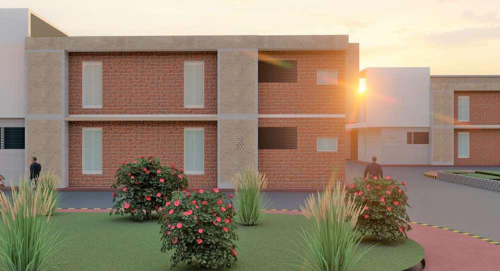
WORKERS RESIDENCE
GROUND FLOOR PLAN (TYPICAL 1ST FLOOR) COLUMN, BEAM AND CENTRE LINE LAYOUT TOP VIEW OF RESIDENCIAL AREA
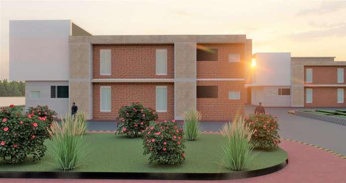
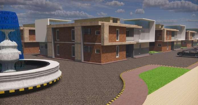
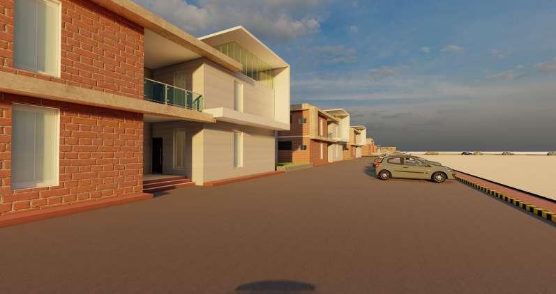
10 I DESIGN
FRONT ELEVATION SIDE ELEVATION 3 4 7 8 10 A B C D E F G H J K L 5.1 4.9 5.1 4.7 5.2 5 4.8 5 5 6.5 7.5 5.7 5.2 5 6.4 3.6 3.5 4.6 6.4 4.6
1 2 3 4 A B C D E 7.3 3.2 7.3 3.8 4.9 3.8 4.9
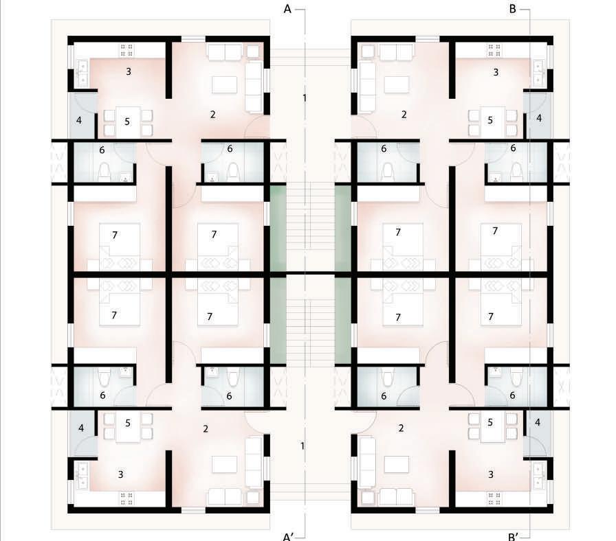
K E Y P L A N SCALE 1:250 RESIDENCE BLOCK SKETCH FRONT ELEVATION SIDE ELEVATION W E N S SCALE 1:150 1. Entry 3m wide 2. Living area - 3.4 x 3.6m 3. Kitchen - 3.4 x 1.7m 4. Utility - 1 x 1.8m 5. Dining area - 3.4 x 1.8m 6. Toilet - 1.5 x 2.4m 7. Beadroom - 3.4 x 3.2m
SECTION AT AA’ SECTION AT BB’
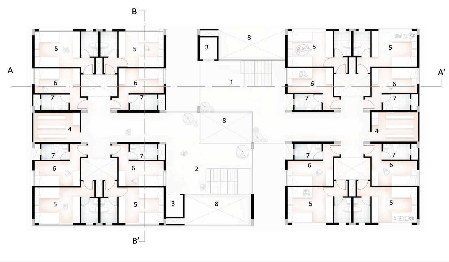
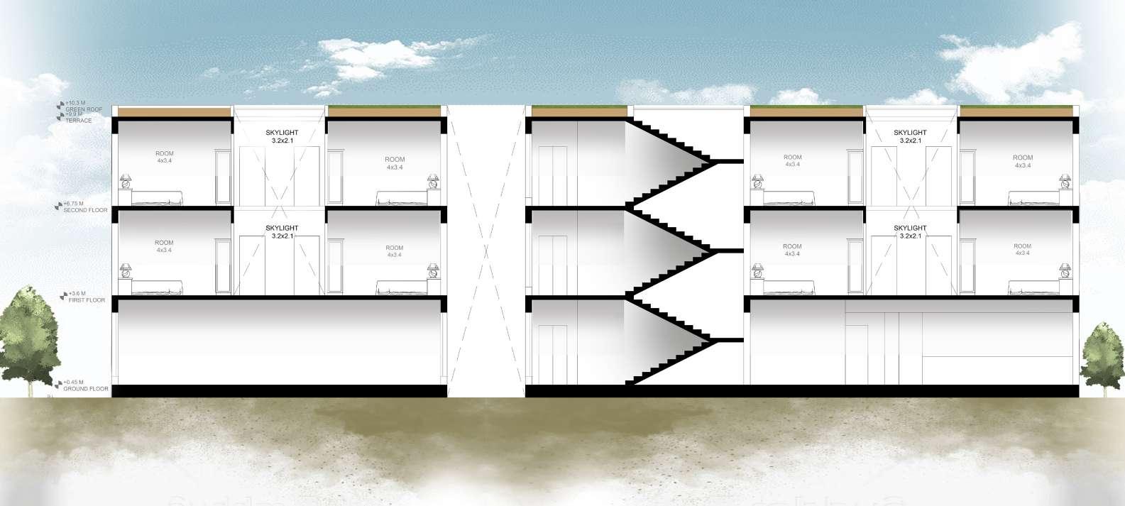
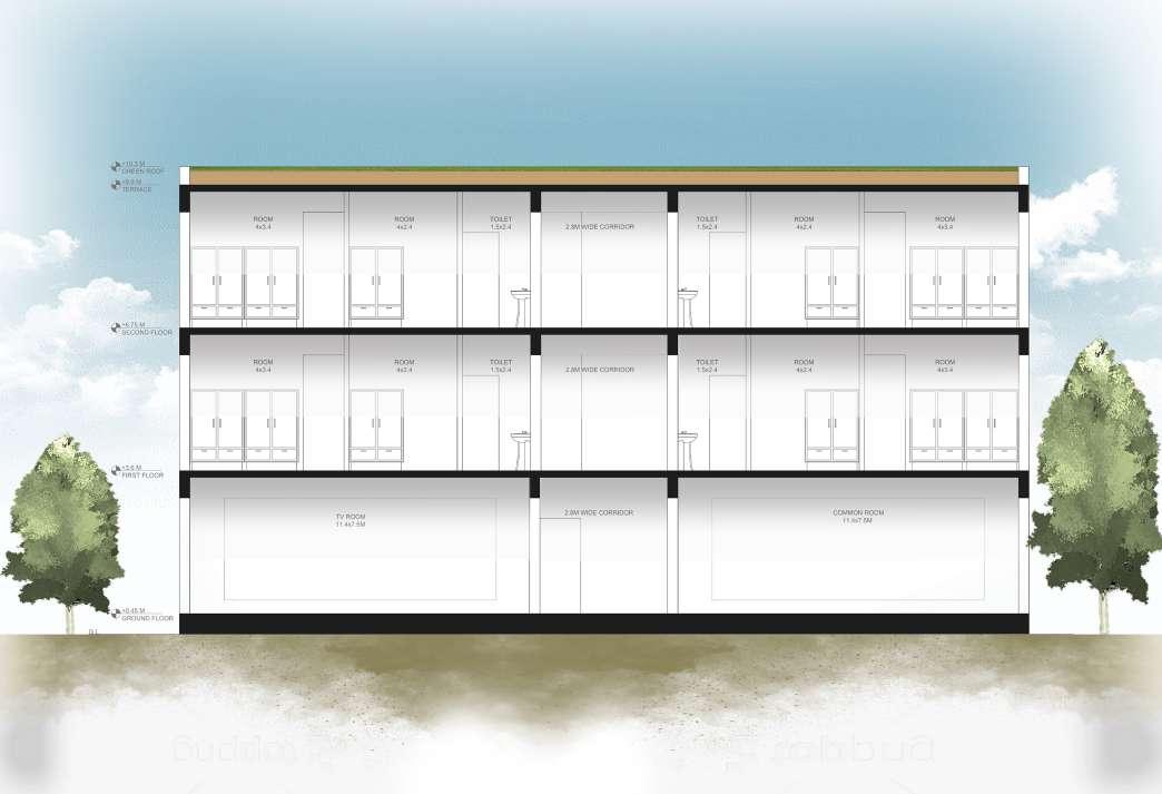
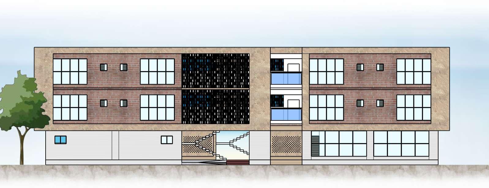


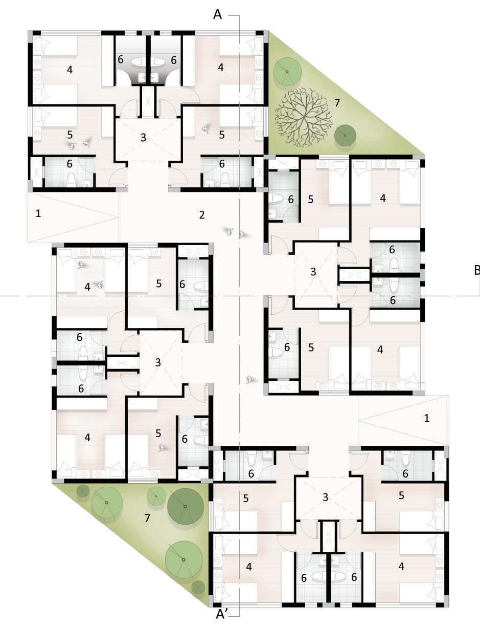
1. Girls hostel entrance - 7.5 x 5.4m 2. Boys hostel entrance - 7.5 x 5.4m 3. Lift 1.5 x 2.1m 4. Office 2.8 x 4m 5. Common room - 11.4 x 7.5m 6. T.V Room 11.4 x 7.5m 7. Dining area 11.5 x 13m 8. Storage 3.5 x 2.5m 9. Washing area - 3.5 x 2.5m 10. Kitchen - 5.3 x 3m 11. Serving area - 5.3 x 2m 12. Service area - 2.5 x 4m GROUND FLOOR PLAN FIRST FLOOR PLAN (TYPICAL FOR SECOND FLOOR) 1. Girls hostle - 7.5 x 5.4m 2. Boys hostle 7.5 x 5.4m 3. Lift 1.5 x 2.1m 4. Laundry - 2.8 x 4m 5. Room (double sharing) 4 x 3.4m 6. Room (single sharing) 4 x 2.4m 7. Toilet - 2.4 x 1.5m 8. Double height 1 3 5 6 8 10 12 9 11 7 5 8 4 2 A B C D 5.6 6 3 7.7 6 5.6 3 4.3 7.7 3 4.3 3 7.7 3 7.7 COLUMN, BEAM AND CENTRE LINE LAYOUT (In meters) SECTION AT AA’ SECTION AT BB’ FRONT ELEVATION Maximum span - 7.7m Minimum span - 3m Column size 0.23 x 0.6m Beam depth 0.45m SCALE 1:150 N S E W HOSTEL BLOCK RESIDENTIAL AREA VIEW HOSTEL BLOCK VIEW SKETCH SHOWING HOSTEL BLOCK KEY PLAN 10 I DESIGN HOSTEL N
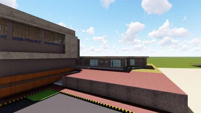
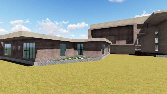
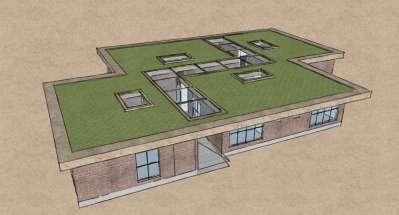
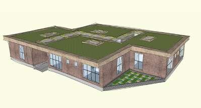
DESIGN DETAILING AND MATERIAL STUDY
• Bijapur has got hot climate.
• So the structure and its surrounding is designed to keep the surrounding cool.
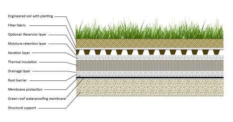
• Here green roof of 550mm is provided at the top of all the building.
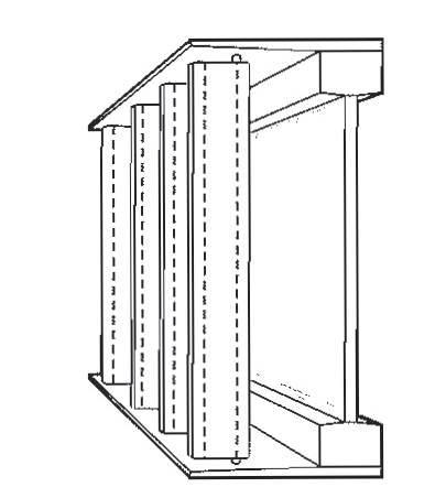
VERTICLE SHADING
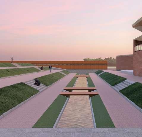
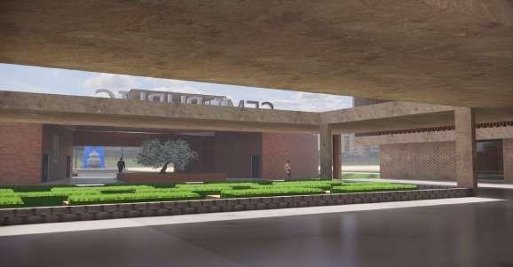
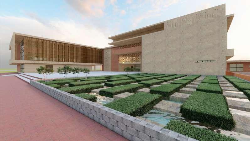
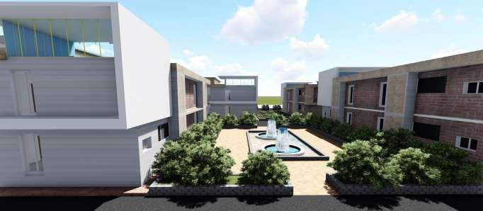
• Courtyards are provided with landscape and flowing water body which helps in taking heat and cooling down.
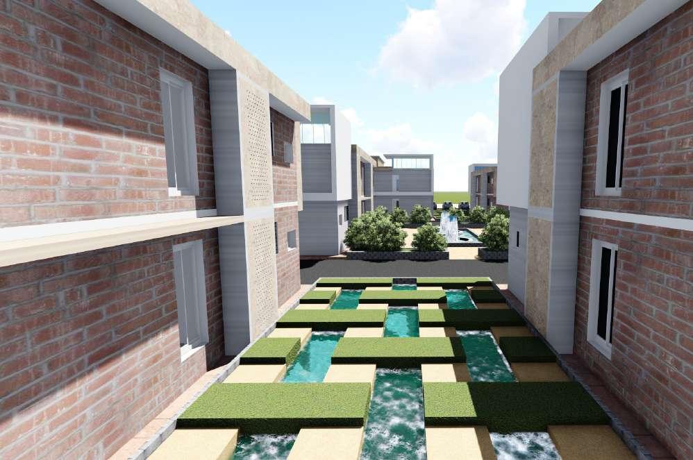
• This is also provided in-between buildings which acts as setback, provide view and also keeps surrounding cool.
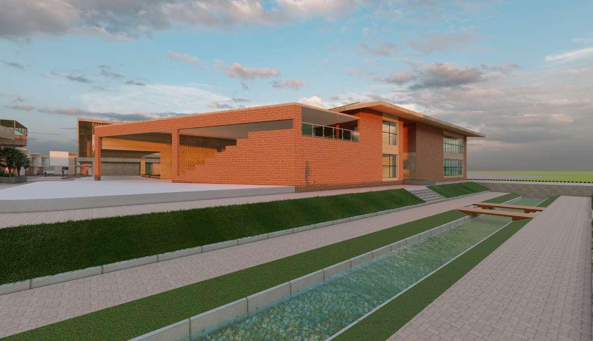
• Exposed brick façade is provided with jaali wall on most of the building.
• This makes the building more sustainable.
• Exposed brick helps in saving cost of plastering.
• Brick masonry can also be arranged in desired pattern.
• Exposed brick is more durable with less maintains.
• Jaali work helps in both reducing heat and noise in the interior.
• Weaving machine produces lots of noise which can affect mental health of the workers.
• So to reduce this noise large openings has to be provided but this is the place where the cloths are weaved hence an open of semi covered structure cannot be given.
• Hence jaali wall are provided to cover it. Even this is provided in the pattern of weaving
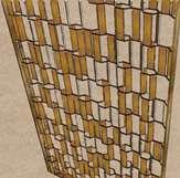
JAALI WORK
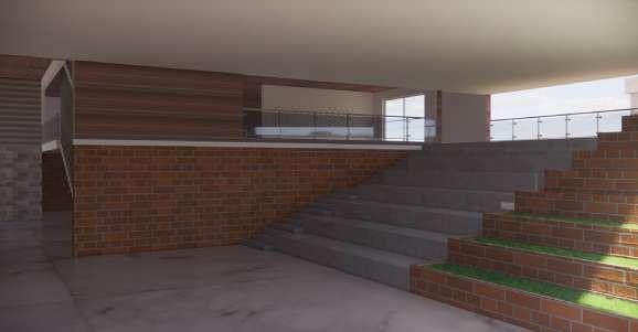
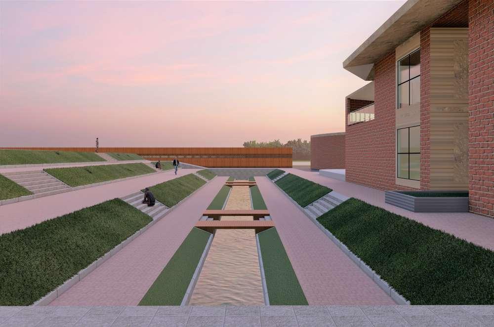
• Landscape with steps are provided to access from entrance to shops this is to match the contour levels.
• This also creates barrier between space.
• Moving water helps in catching heat and create cool environment.
• This space can also be used for temporary stalls and food court.
Vertical shading device helps in blocking harsh sunlight and let only reflected light to interior. And also this acts as jaali wall which also cool down the hot air.
10 I DESIGN
GROUND FLOOR PLAN 1 A 2 C E B D 7.7 5.8 5.8 2.2 4.7 4.7 COLUMN,
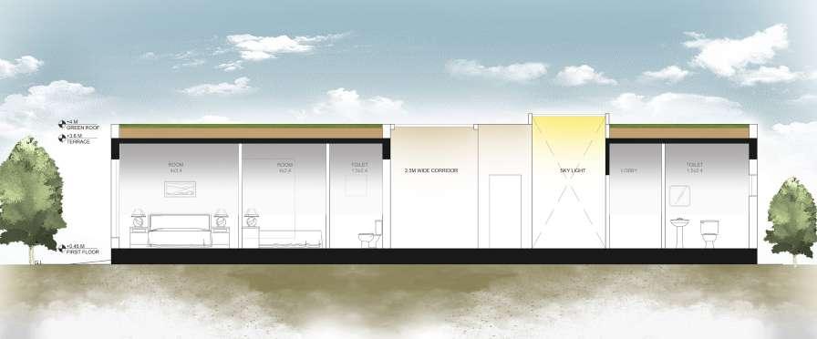
DETAIL SECTION AT AA’ SECTION AT BB’ GUEST HOUSE W E N S SCALE 1:150 1. Entry 3m wide 2. Corridor - 3m wide 3. Sky Light - 3.2 x 2.1m 4. Room 1 - 4 x 3.4m 5. Room 2 - 4 x 2.4m 6. Toilet 2.4 x 1.5m 7. Landscape view FRONT ELEVATION
KEY PLAN
GUEST HOUSE
BEAM
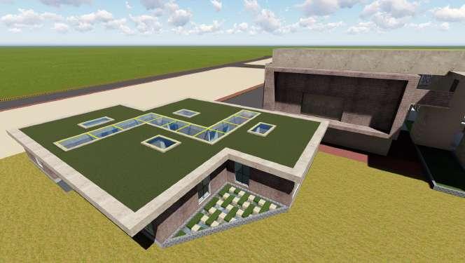
3D VIEW OF GUEST HOUSE
GREEN ROOF
LANDSCAPE COURTYARD
LANDSCAPE TO MATCH CONTOUR
EXPOSED
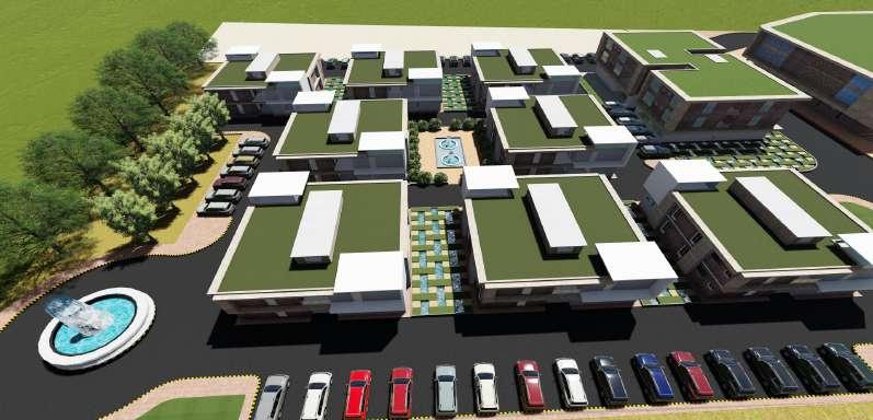
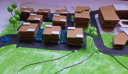
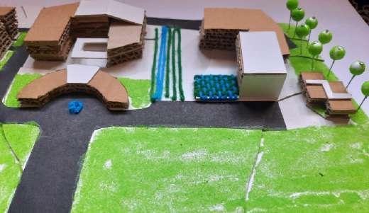
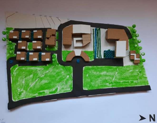
3 D P H Y S I C A L M O D E L
BRICK FACADE
