ADA CHECKLIST
Issue 5/10/23
Effective 9/1/2023 Project No.
PEDESTRIAN SIDEWALKS
Figures/Definitions Requirements 1
Sidewalk Width
Width Measurements: All width dimensions shall be exclusive of the width of adjacent curb.
Pedestrian Access Route: A continuous and unobstructed path of travel provided for pedestrians with disabilities within or coinciding with a pedestrian circulation path.
Pedestrian Circulation Path: A prepared exterior or interior surface provided for pedestrian travel in the public right-of-way.
• Sidewalks within St. Louis County right of way shall be 5 feet wide minimum for arterial (ARS), collector (CRS-2), and non-residential (CRS) roads. Clear width may be reduced to 4 feet only when necessary to avoid obstacles which cannot be practicably relocated. 2
• Sidewalks shall have a continuous and unobstructed clear width of 4 feet wide minimum along residential (CRS) subdivision streets.
• Where 4’ sidewalks are provided, 5 foot x 5 foot passing spaces shall be provided at intervals of 200 feet maximum. Driveway approaches may be used to meet the passing space requirement.
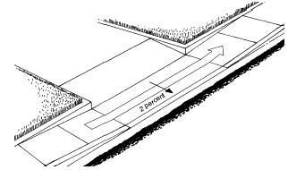
• St. Louis County Sidewalks located within 2 feet of the back of curb are to be constructed 6 feet wide minimum and constructed adjacent to the back of the curb for all development types. 2

• Detectable warning surfaces shall be provided, where a pedestrian access route connects to or crosses a street, signalized commercial entrance, commercial driveway permitted to operate like a public street, pedestrian rail crossings, or pedestrian refuge island.
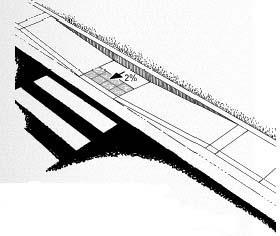
• Where sidewalk stubs are constructed with no pedestrian outlet, a turning space shall be constructed at the sidewalk terminus with a minimum width as defined by the road classification2 and a minimum length of 4 feet. The turning space shall have a maximum running slope and cross slope of 2.0 percent. The Road Grade Exception is not applicable to this pedestrian access route feature. 2
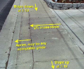
Running Slope: The grade that is parallel to the direction of travel, expressed as a ratio of rise to run or as a percent.
• The running slope of a pedestrian access route shall be 5 percent maximum where not contained within a roadway right-of-way and where the pedestrian access route exceeds the general grade of the adjacent roadway.
• Where sidewalks are contained within a street or highway right-of-way, the grade of the sidewalk is permitted to equal the general grade established for the adjacent street or highway This exception does not apply within a cross walk
Cross Slope: The grade that is perpendicular to the direction of accessible pedestrian travel, measured perpendicular to the curb line or edge of the street or highway, or measured perpendicular to the running grade.
Vertical Alignment
• The maximum cross slope of the walkway of a pedestrian access route shall be 2.0 percent. Cross slope exceptions can be found in sections “PEDESTRIAN STREET CROSSINGS” and “CURB RAMPS”. Cross slope shall be defined as the grade that is perpendicular to the direction of accessible pedestrian travel, measured perpendicular to the curb line or edge of the street or highway, or measured perpendicular to the running grade.

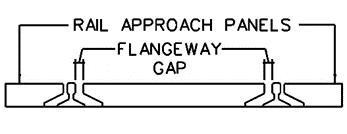
• Vertical alignment shall be planar within curb ramp runs, blended transitions, turning spaces, and gutter areas within the pedestrian access route, and within clear spaces required for accessible pedestrian signals, street furniture, and operable parts. Surface slopes that meet at grade breaks shall be flush. Where the pedestrian access route crosses rail tracks at grade, the surface of the pedestrian access route shall be level and flush with the top of the rail at the outer edges of the rail. The surface between the rails shall be aligned with the top of the rail.
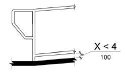
of ¼ inch high maximum shall be permitted to be vertical. Changes in level between ¼ inch high maximum and ½ inch high maximum shall be or flatter. The bevel shall be applied across the entire

No change in level is permitted where Curb Ramps, Blended Transitions, Turning or Sidewalks meet gutter and roadway grade; this transition must be flush.
• Protruding objects on sidewalks and other pedestrian circulation paths shall not reduce the clear width to less than 4 feet minimum
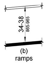
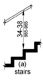
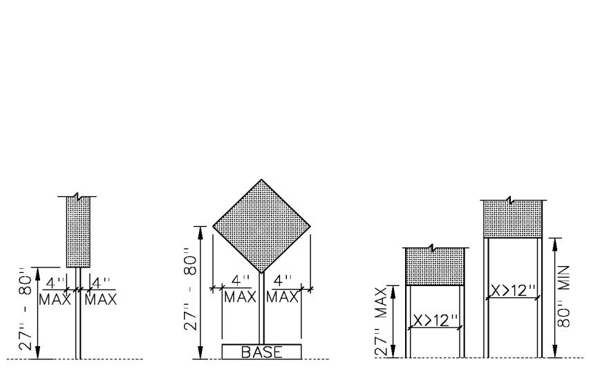
• Objects with leading edges more than 27 inches and not more than 80 inches above the finish floor or ground shall protrude 4 inches maximum horizontally into the circulation path.
• The dimensions of the base for post mounted objects which protrude into the pedestrian access route shall be 2.5 inches thick minimum and the width shall extend to within 4 inches horizontally from the protruding edge of the object.
• Where a sign or other obstruction is mounted between posts or pylons and the clear distance between the posts or pylons is greater than 12 inches, the lowest edge of such sign or obstruction shall be 27 inches maximum or 80 inches minimum above the finish floor or ground.
• Vertical clearance shall be 80 inches high minimum. Pedestrian barriers shall be provided where the vertical clearance is less than 80 inches high. The leading edge of such guardrail or barrier shall be located 27 inches maximum above the finish floor or ground.
PEDESTRIAN SIDEWALKS
Figures/Definitions Requirements 1
Openings
Tip: Plugging of holes greater than ½ inch with a material approved by the engineer is acceptable as long as it complies with the changes in level requirements. 2
• Openings in floor and ground surfaces, including utility covers, shall not allow passage of a sphere more than ½ inch diameter. Elongated openings shall be placed so that the long dimension is perpendicular to the dominant direction of travel.
PEDESTRIAN STREET CROSSINGS
Figures/Definitions Requirements 1 YES NO NA Intersection crosswalks are not required to be marked at nonsignalized intersections.
Crosswalk marking needs will be determined by the St. Louis County Division of Operations.
• All intersections with a minimum of 3 legs, both signalized and non-signalized, shall be constructed with accessible pedestrian street crossings. Exceptions will be made on a case by case basis for documented safety concerns.
• The running grade of the pedestrian access route within a street crossing shall be 5 percent maximum, measured parallel to the direction of pedestrian travel in the crosswalk.
• Crossings without yield or stop control shall have a cross slope of 5 percent maximum.
• Crossings with yield or stop control shall have a maximum cross slope of 2.0 percent.
◼ Exception: A yielding right turn movement at a signalized intersection may use a cross slope up to 5 percent.

• The cross slope at midblock crossings shall be permitted to meet street or highway grade
• Midblock pedestrian crossings must be marked to be legal crossings.
• All pedestrian signal phase timing shall be calculated using a pedestrian walk speed of 3.5 ft/s maximum. The crosswalk distance used in calculating pedestrian signal phase timing shall include the entire length of the crosswalk.
• Crosswalk pavement marking is 12 inches wide white.
• Stop bar is at least 4 feet from the crosswalk.
• Curb ramps at marked crossings shall be wholly contained within the markings, excluding any flared sides.
• Gratings, access covers, and other appurtenances shall not be located on curb ramps, landings, blended transitions, and gutters within the pedestrian access route.
• Grade breaks shall not be permitted on the surface of curb ramps, blended transitions, landings, or gutter areas within the pedestrian access route. Surface slopes that meet at grade breaks shall be flush.
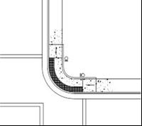
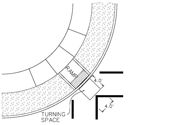
• Roundabouts:
Figures/Definitions
PEDESTRIAN STREET CROSSINGS
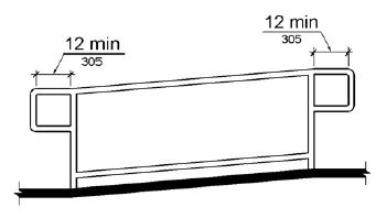
◼ When sidewalks are flush against the curb, a continuous detectable edge treatment (NOT a detectable warning surface) shall be provided where crossings are not intended. Where chains, fencing, or railings are used, the bottom edge shall be no more than 15 in above the sidewalk.
◼ Where multilane crossings exist, pedestrian actuated signals are required.
• Pedestrian activated signals shall be provided at pedestrian crossings at multi-lane channelized turn lanes at signalized intersections.
CURB RAMPS
Figures/Definitions
A curb ramp, blended transition, or a combination of curb ramps and blended transitions shall connect the pedestrian access routes at each pedestrian street crossing.
Cross Slope: The grade that is perpendicular to the direction of accessible pedestrian travel, measured perpendicular to the curb line or edge of the street or highway, or measured perpendicular to the running grade.
15 Foot Rule: For a compliant Curb Ramp to exceed 8.33 percent running grade, its constructed length must exceed 15.0 feet.
• CURB RAMPS exist only where transitioning from sidewalk grade to street grade within the public right-of-way. A curb ramp, blended transition, or a combination of curb ramps and blended transitions shall connect the pedestrian access routes at each pedestrian street crossing.
• Curb Ramps shall all follow all criteria in the “CURB RAMPS” section in addition to the ramp type specific criteria in curb ramp subsections 1 – 6, as applicable.
• New construction and redevelopment projects shall incorporate a design that provides individual ramps for each crossing direction.
• The clear width of Curb Ramps, excluding flares, shall be 5.0 feet wide minimum for arterial (ARS) and collector (CRS-2) roads 2 Curb Ramp width may be reduced to 4 feet wide along residential (CRS) subdivision streets.
• Curb Ramp runs shall have a running slope between 5 percent minimum and 8.33 percent maximum but shall not require the ramp length to exceed 15.0 feet.
◼ Exception: 15 Foot Rule: The running slope for a curb ramp is not limited to 8.33 percent maximum if the constructed curb ramp length exceeds 15 feet in length.
• Permeable pavement shall not be permitted for construction of Curb Ramps, blended transitions, or turning spaces. 2
• Curb Ramp and Blended Transition cross slope requirements:
◼ The maximum cross slope at intersections with stop or yield control shall be 2.0 percent.
◼ The cross slope at intersections without stop or yield control, where vehicles can proceed through the intersection without slowing or stopping, shall be 5 percent maximum.
◼ The maximum cross slope for yielding right turn movements at signalized intersections shall be 5 percent. 2
◼ The cross slope at midblock crossings shall be permitted to meet street or highway grade.
CURB RAMPS

• Turning Spaces shall be required at the top of all Curb Ramps where turning movements are required:
◼ Turning spaces shall be 4.0 feet minimum by 4.0 feet minimum. If the turning movement is at back of sidewalk or constrained on two sides, the turning space shall be 4.0 feet minimum by 5.0 feet minimum. See PROWAG 2011 sections R304.2.1 and R304.3.1 for the location of the 5.0 feet dimension.
◼ Turning spaces shall have a maximum cross slope of 2.0 percent.
◼ Turning spaces shall have a maximum running slope of 2.0 percent.
• A Clear space shall be provided beyond the bottom grade break of all Curb Ramps.
◼ The Clear space shall be a minimum of 4 feet by 4 feet.
◼ The Clear space shall reside wholly outside of the parallel vehicle travel lane.
◼ Clear spaces shall be permitted to overlap other Turning and Clear spaces.
• Handrails and Edge protection shall not be required on curb ramps, their landings, or their clear spaces.
• Street and ramp slope break is 13 percent or less. (See adjacent figure.)
• No change in level is permitted where Curb Ramps, Blended Transitions, Turning Spaces or Sidewalks meet gutter and roadway grade; this transition must be flush
• Flared sides with a slope of 10 percent maximum, measured parallel to the curb line, shall be provided where a pedestrian circulation path crosses the curb ramp.
• In alterations, where there is no landing at the top of curb ramps, curb ramp flares shall be provided and shall not be steeper than 1:12. 2
• Detectable warning surfaces shall be provided, where a pedestrian access route connects to or crosses a street, signalized commercial entrance, commercial driveway permitted to operate like a public street, pedestrian rail crossings, or pedestrian refuge island.
• Gratings, access covers, and other appurtenances shall not be located on Curb Ramps, blended transitions, turning spaces, clear spaces, or gutters within the pedestrian access route.
◼ Exception: For alteration type projects, gratings, access covers, and other appurtenances may be located within Curb Ramps, blended transitions, clear spaces and gutters when relocation of said features is not practicable.
• Grade breaks shall not be permitted on the surface of curb ramps, blended transitions, landings, or gutter areas within the pedestrian access route. Surface slopes that meet at grade breaks shall be flush.
• Grade Breaks at the top and bottom of curb ramp runs shall be perpendicular to the direction of the ramp run.
Figures/Definitions
CURB RAMPS
Parallel Curb Ramp
CURB RAMP SUBSECTION 1: PARALLEL CURB RAMPS
• Parallel Curb Ramps shall have a running slope that is in-line with the direction of sidewalk travel. (PROWAG 2011, R304.3)
• Parallel curb ramps must follow all criteria in the “CURB RAMPS” section in addition to the criteria of subsection 1.

• A Turning Space shall be required at the bottom of all parallel curb ramps and shall be permitted to overlap other turning spaces and clear spaces:
◼ Turning spaces shall be 4.0 feet minimum by 4.0 feet minimum. If the turning movement is at back of sidewalk or constrained on two sides, the turning space shall be 4.0 feet minimum by 5.0 feet minimum. See PROWAG 2011 sections R304.2.1 and R304.3.1 for the location of the 5.0 feet dimension.
◼ Turning spaces shall have a maximum slope of 2.0 percent perpendicular to the sidewalk running grade.
◼ Turning spaces shall have a slope equal to the adjacent road grade parallel to the sidewalk running grade.
CURB RAMP SUBSECTION 2: PERPENDICULAR CURB RAMPS
Figures/Definitions Requirements 1
• Perpendicular Curb Ramps shall have a running slope that cuts through or is built up to the curb at right angles or meets the gutter grade break at right angles. (PROWAG 2011, R304.2 & R304.5)
• Perpendicular curb ramps must follow all criteria in the “CURB RAMPS” section in addition to the criteria of subsection.
• A Turning Space shall be required at the top of all perpendicular curb ramps where a turning movement is required and shall be permitted to overlap other turning spaces.
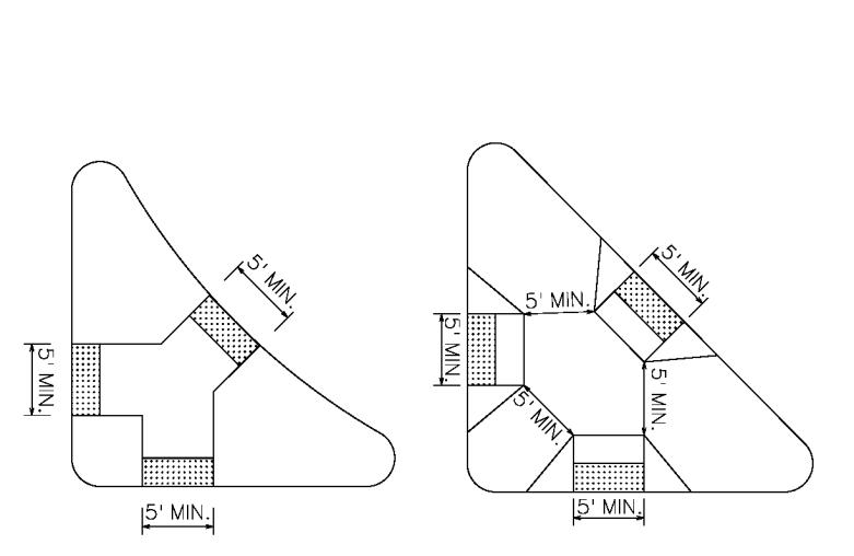
• Turning spaces shall be 4.0 feet minimum by 4.0 feet minimum. If the turning movement is at back of sidewalk or constrained on two sides, the turning space shall
Figures/Definitions
Flared Sides in Pathway –Turning Space Constrained By Building – X=5’ Min
CURB RAMPS
be 4.0 feet minimum by 5.0 feet minimum. See PROWAG 2011 sections R304.2.1 and R304.3.1 for the location of the 5.0 feet dimension.
• Turning spaces shall have a maximum cross slope of 2.0 percent.
• Turning spaces shall have a maximum running slope of 2.0 percent.
• Flared sides with a slope of 10 percent maximum, measured parallel to the curb line, shall be provided where a pedestrian circulation path crosses the curb ramp.
• Where the pedestrian circulation path does not cross the Curb Ramp (grass next to ramp), then vertical curb returns shall be constructed adjacent to the Curb Ramp.
Flared Sides Not in Pathway – Turning Space Not Constrained – X=4’ Min
• Where both ends of the bottom grade break are 5.0 feet or less from the back of curb, the detectable warning shall be located on the ramp surface at the bottom grade break. Where either end of the bottom grade break is more than 5.0 feet from the back of curb, the detectable warning shall be located on the lower landing.
CURB RAMP SUBSECTION 3: BLENDED TRANSITIONS
• Blended Transitions must follow all criteria in the “CURB RAMPS” section in addition to the criteria of subsection 3.
• Blended Transitions shall have a running slope of 5 percent maximum.
• Detectable warning shall be placed at the back of curb..
• Where level pedestrian street crossings are provided, detectable warnings shall be placed at the flush transition between the street and the sidewalk.
CURB RAMP SUBSECTION 4: DIAGONAL CURB RAMPS
• A Diagonal Curb Ramp is a single parallel or perpendicular Curb Ramp which serves two crossings. Diagonal Curb Ramps shall not be permitted for new construction or redevelopment projects. Diagonal Curb Ramps may only be used for alteration type projects where construction of split Curb Ramps is not practicable.
• Diagonal Curb Ramps must follow all criteria in the “CURB RAMPS” section and applicable subsections
• Diagonal Curb Ramps shall provide a minimum 4 foot by 4 foot turning space beyond the curb line and wholly outside of the both parallel vehicle travel lanes. At marked crossings, the turning space shall be contained within the crosswalk markings.

Figures/Definitions
ENTRANCES
• The minimum continuous and unobstructed clear width of a pedestrian access route provided across commercial and residential entrances shall be 4 feet.

• Cross slope shall be 2.0 percent maximum.
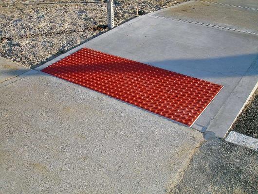
DETECTABLE WARNING DEVICES (TRUNCATED DOMES)
Figures/Definitions Requirements 1
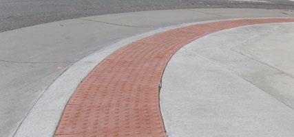
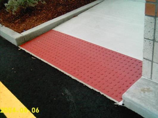
• Detectable warnings shall consist of a surface of truncated domes aligned in a square or radial grid pattern complying with 2010 ADA Standards. All detectable warning products shall require approval by St. Louis County prior to installation.2
NO NA Surface feature of truncated dome material built in or applied to the walking surface to advise of an upcoming change from pedestrian to vehicular way.
• Detectable warning surfaces shall contrast visually with adjacent gutter, street or highway, or walkway surfaces, either light-on-dark or dark-on-light.
• Detectable warning surfaces shall extend 24 inches in the direction of travel and the full width of the curb ramp (exclusive of flares), the landing, or the blended transition. Exception, when detectable warnings are required by a manufacturer’s installation specifications to be embedded into concrete with a surrounding edge, domes may be installed at less than the required full width. However, the detectable warning surface shall never be more than 2 inches from the edge of the curb ramp, the landing, or the blended transition.
• Detectable warning surfaces shall be installed where a pedestrian access route connects to a public street, signalized commercial entrance, or commercial driveways which are permitted to operate like a public street.
• Pedestrian route crossings of residential driveways shall not be provided with detectable warnings.
• Perpendicular Curb Ramps: Where both ends of the bottom grade break are 5 feet or less from the back of curb, the detectable warning shall be located on the ramp surface at the bottom grade break. Where either end of the bottom grade break is more than 5 feet from the back of curb, the detectable warning shall be located on the lower landing.
• Parallel Curb Ramps: Detectable warning surfaces shall be placed on the turning space at the flush transition between the street and sidewalk.
• Landings and Blended Transitions: The detectable warning shall be located on the landing or blended transition at the back of curb.
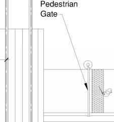
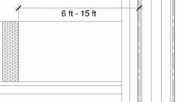
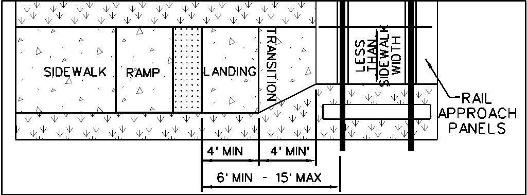
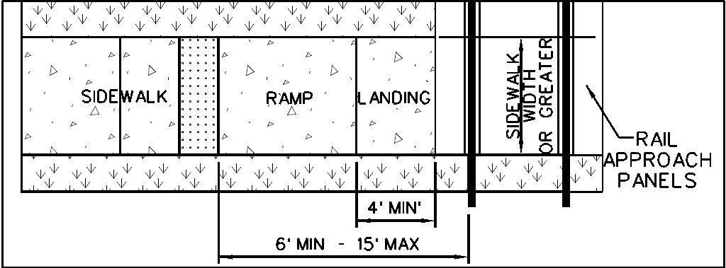
• At pedestrian at-grade rail crossings not located within a street or highway, detectable warning surfaces shall be placed on each side of the rail crossing. The edge of the detectable warning surface nearest the rail crossing shall be 6.0 feet minimum and 15.0 feet maximum from the centerline of the nearest rail. Where pedestrian gates are provided, detectable warning surfaces shall be placed on the side of the gates opposite the rail.
• Detectable warnings at cut-through islands shall be located at the curb line in-line with the face of curb and shall be separated by a 2.0 foot minimum length of walkway without detectable warnings. Where the island has no curb, the detectable warning shall be located at the edge of roadway.
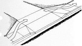
Ramped Island
ISLANDS AND MEDIANS
Requirements 1
• Medians and pedestrian refuge islands in crosswalks shall contain a pedestrian access route, including passing space and connecting to each crosswalk.
• Raised islands in crossings shall be cut through level with the street or have Curb Ramps at both sides.
• Curb Ramps used for ramped islands shall meet all criteria of section “CURB RAMPS” in addition to section “ISLANDS AND MEDIANS”.
• All median and island passage spaces shall provide a clear width of 5 feet minimum.
• Medians and pedestrian refuge islands shall be 6.0 feet minimum in length in the direction of pedestrian travel. 2
• Island Curb Ramp and cut through cross slope requirements:
◼ The cross slope at intersections with stop or yield control shall be 2 percent maximum.
◼ The cross slope at intersections without stop or yield control, where vehicles can proceed through the intersection without slowing or stopping, shall be 5 percent maximum.
◼ The cross slope at midblock crossings shall be permitted to meet street or highway grade.
• The running grade of the pedestrian access route within an island or median shall be 5 percent maximum, exclusive of Curb Ramps, measured parallel to the direction of pedestrian travel.
• Ramped islands shall have a turning space 5 feet long minimum by 5 feet wide minimum at the top of each ramp Cross slope and running slope of the turning space is permitted to equal the grade of the adjacent roadway up to maximum of 5 percent.
• The raised portions of cut through islands and medians shall be a minimum of 4 feet on a side. 2
• Detectable warnings at cut-through islands shall be located at the curb line in-line with the face of curb and shall be separated by a 2.0 foot minimum length of walkway without detectable warnings. Where the island has no curb, the detectable warning shall be located at the edge of roadway.
Figures/Definitions
Sidewalk Ramps
For example, a ramp segment with the maximum allowed running slope of 8.33% would require 5’ x 5’ landing after every 30’ of run.

SIDEWALK RAMPS
• A SIDEWALK RAMP is a sidewalk segment with a running grade in excess of 5 percent but less than 8.33 percent which is not a curb ramp (a curb ramp only exists where transitioning from sidewalk grade to road grade) nor exempted by the Roadway Grade Exception.
• The clear width of Sidewalk Ramps, excluding flares, shall be 5.0 feet wide minimum along arterial (ARS) and collector (CRS-2) roads Sidewalk Ramp width may be reduced to 4 feet wide along residential (CRS) subdivision streets. 2
• Cross slope of Sidewalk Ramp runs shall be 2.0 percent maximum.
• The rise for any ramp run shall be 30 inches maximum.
• Sidewalk Ramps shall have level landings at the top and the bottom of each ramp run. Level landings shall be at least as wide as the widest ramp leading to the landing, be a minimum of 5 feet in length and have a 2.0 percent maximum slope in any direction.
• Edge protection shall be provided on each side of Sidewalk Ramp runs and Sidewalk Ramp landings.
• Sidewalk Ramp runs outside public right of way with a rise greater than 6 inches are required to have handrails.
• When handrail is provided, it shall be provided on both sides of stairs and Sidewalk Ramps.
• Gratings, access covers, and other appurtenances shall not be located on ramps, landings, blended transitions, or gutters within the pedestrian access route.
• Grade breaks shall not be permitted on the surface of ramps, blended transitions, landings, or gutter areas within the pedestrian access route.
• Surface slopes that meet at grade breaks shall be flush.
Accessible Pedestrian Signals and Pedestrian Pushbuttons
Figures/Definitions
An accessible pedestrian signal and pedestrian pushbutton is an integrated device that communicates information about the WALK and DON’T WALK intervals at signalized intersections in non-visual formats (i.e., audible tones and vibrotactile surfaces) to pedestrians who are blind or have low vision.
• Pedestrian signals shall include accessible pedestrian signals and pedestrian pushbuttons complying with Sections 4E.08 through 4E.13 of the MUTCD.
• Pushbuttons shall be pressure activated piezo type with momentary LED and audible alert and be mounted 42 inches above the paved landing with the face of the push button parallel with the associated crosswalk.
• Pushbuttons shall require no more than 5 lbs to activate.
Accessible Pedestrian Signals and Pedestrian Pushbuttons
• Pushbuttons shall be located to meet the following criteria:
◼ Adjacent to a clear space (see below)
◼ An accessible route from the pushbutton to the ramp.
◼ Between the edge of the crosswalk line (extended) farthest from the center of the intersection and the side of a curb ramp (if present) but not more than 5 feet from said crosswalk line. (Subject to physical constraints)
◼ Between 1.5 and 6.0 ft from the edge of the curb, shoulder, or pavement. (Subject to physical constraints)
◼ With face of the pushbutton parallel to the crosswalk to be used.
◼ Mounting height of 42 inches.2
Where two pedestrian pushbuttons are provided on the same intersection corner or within the same island, the pushbuttons shall be separated by a distance of at least 10 feet
◼ Exception for alteration type projects only: If physical constraints make this impractical, the pushbuttons may be placed closer together or on the same pole.
• Signs shall be mounted adjacent to or integral with pedestrian push buttons.
• APS Requirements (in addition to those above) (MUTCD 2009, 4E.09 to 4E.13):

◼ Tactile arrows with high visual contrast clearly indicating which crosswalk signal is actuated by the pushbutton shall be located on each pushbutton, aligned parallel to the direction of travel
◼ Pushbutton locator tones which adjust intensity in accordance with ambient noise shall be provided.
◼ If two accessible pushbuttons are at least 10 feet apart, the audible walk indication shall be a percussive tone, repeating eight to ten ticks per second.
◼ If two accessible pushbuttons are less than 10 feet part or on the same pole, each accessible pushbutton shall have the following features:
▪ Pushbutton locator tone,
▪ Tactile arrow,
▪ Speech walk message for the WALKING PERSON indication, and
▪ Speech pushbutton information message.
◼ If the pedestrian clearance time is set to only allow a pedestrian to cross to the median, an additional pedestrian detector shall be provided in the median.
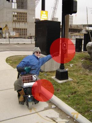
Non-compliant push button installation restricts access for disabled pedestrians.
◼ APS shall have both audible and vibrotactile walk indications. The accessible walk indication shall have the same duration as the pedestrian walk signal except when the pedestrian signal rests in walk. Audible walk indications shall be during the walk interval only and be audible from the beginning of the associated crosswalk. The tactile arrow on the pushbutton shall vibrate during the walk interval.
• Clear spaces:
◼ Compliant with Surface and Vertical Discontinuity section above with a maximum cross slope of 2.0%.
▪ Exception: Within Islands and medians, the cross slope of the clear space adjacent to the push button may match the cross slope requirements in the “ISLANDS AND MEDIANS” section.
◼ At least 2.5 ft by 4.0 ft.
▪ Space below the pushbutton may be included as clear space if knee and toe clearance is provided (see below).
◼ Positioned for either forward or parallel approach.
◼ At least one full unobstructed side of a clear space shall adjoin a pedestrian access route or adjoin another clear space as an approach.
◼ Where confined on all or part of three sides, additional maneuvering space shall be provided:
▪ Forward approach: Clear space and additional maneuvering space shall be at least 3.0 ft wide where the depth exceeds 2.0 ft.
▪ Parallel approach: Clear space and additional maneuvering space shall be at least 5.0 ft wide where the depth exceeds 1.25 ft.
• Toe Clearance: From the finish surface to 9 in above the finish surface.
◼ Shall extend between 17 and 25 inches (inclusive) under the element.
◼ The width shall be at least 2.5 ft.
• Knee Clearance: From 9 to 30 in above the above the finish surface.
◼ Shall extend between 11 and 25 inches (inclusive) under the element and may be reduced by 1 in of depth for each 6 inches in height.
◼ The width shall be at least 2.5 ft.
• Reach Range:
◼ Forward Approach: Pushbutton must be even with the edge of the clear space (no offset is permitted).
◼ Parallel Approach: Side reach of no more than 10 inches is permitted.
• Clear spaces, turning spaces, and landings at APS, pushbuttons, and other accessible elements may have a running slope or cross slope consistent with the grade of the adjacent pedestrian access route or roadway.
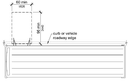
BUS BOARDING AND ALIGHTING AREAS
Figures/Definitions Requirements 1
• Bus stop boarding and alighting areas shall have a firm, stable surface.
• Bus stop boarding and alighting areas shall provide a clear length of 8 feet minimum, measured perpendicular to the curb or vehicle roadway edge
• Bus stop boarding and alighting areas shall provide a clear width of 5 feet minimum measured parallel to the vehicle roadway.
• Bus stop shelters, boarding and alighting areas shall be connected to streets, sidewalks, or pedestrian paths by an accessible route.
• Parallel to the roadway, the slope of the bus stop boarding and alighting area shall be the same as the roadway, to the maximum extent practicable.
• Perpendicular to the roadway, the slope of the bus stop boarding and alighting area shall be 2.0 percent maximum.
• Bus shelters shall provide a minimum 30 inch by 48 inch clear floor or ground space entirely within the shelter.
EDGE PROTECTION
Figures/Definitions Requirements 1
• Edge protection shall be provided on each side of Sidewalk Ramp runs and at each side of the adjacent Sidewalk Ramp landings.
• Edge protection shall not be required on Curb Ramps or their associated landings, turning spaces, or clear spaces.
• Edge protection shall not be required on the sides of Sidewalk Ramp landings having a vertical drop-off on ½ inch maximum within 10 inches horizontally of the minimum landing area. 2
• The floor or ground surface of the Sidewalk Ramp run or landing shall extend 12 inches minimum beyond the inside face of a handrail.

• A curb or barrier shall be provided that prevents the passage of a 4 inch diameter sphere, where any portion of the sphere is within 4 inches of the finish floor or ground surface.
YES NO NA
YES NO NA
STAIRWAYS
• All steps on a flight of stairs shall have uniform riser heights and uniform tread depths. Risers shall be 4 inches high minimum and 7 inches high maximum. Treads shall be 11 inches deep minimum.
• Open risers are not permitted.
• The radius of curvature at the leading edge of the tread shall be 1/2 inch maximum. Nosings that project beyond risers shall have the underside of the leading edge curved or beveled. Risers shall be permitted to slope under the tread at an angle of 30 degrees maximum from vertical. The permitted projection of the nosing shall extend 1 1/2 inches maximum over the tread below.
• Stairs shall have handrails complying with PROWAG 2011 R409.
Truncated Dome Placement
No Pedestrian Gates