Residential ATTACHED GARAGE Checklist and Guide For a Building Permit
(Per the 2015 IRC as amended by St. Louis County Ordinances for 1-& 2-Family Dwellings and Townhouses

This Attached Garage Checklist is based on St. Louis County’s (SLCO) policies, construction codes amended and adopted by ordinance. See list below. It is not a substitute for those codes and ordinances, but serves as a guide to reading them. More information and explanation is provided in commentaries and interpretations published by St. Louis County and acknowledged code organizations.
RESIDENTIAL ATTACHED GARAGES REQUIREMENTS
(Per the 2015 IRC as amended by St. Louis County Ordinances for 1-& 2-Family Dwellings and Townhouses)
List of Applicable Codes and Ordinances:
2015 International Residential Code (IRC) & Ordinance #27,654-Ch.1116 (“R” “G”, “N”, and “M” references and Appendix K - Sound Transmission)
2015 International Building Code (IBC) & Ordinance #27,654-Ch.1116\5 (“B” references).
2014 National Electrical Code (NEC) aka NFPA 70 & Ordinance #24439-Ch.1102 (“E” references).
For inquiries regarding the information provided in this guide, please contact:
Louis County Permit Processing (314) 615-5184

Louis County Zoning Review
615-3763
615-5485
St. Louis County’s Municipal Contracts Matrix shows those municipalities that currently contract for its Code Enforcement services. The Matrix is on our web site at https://stlouiscountymo.gov/st-louis-county-departments/transportation-and-publicworks/residential-building/
For the electronic plan review, scan QR code or visit us online at https://stlouiscountymo.gov/st-louis-county-departments/transportation-and-publicworks/electronic-plan-review/
Sections from the Codes, their Referenced Standards, and St. Louis County Ordinances, are shown at ends of statements and are italicized in parentheses (.)

NOTICES Regarding Permits
• The applicant (property owner or the owner’s authorized agent) is responsible for contacting those applicable agencies that may be affected by the new work, or that may have legal oversight of the new work along with but separate from St. Louis County. Where requirements among the agencies conflict, the most restrictive shall govern the new work. Contact these agencies before beginning work approved under a permit issued by St. Louis County. Such agencies may include:
1. The project site’s Municipality;
2. The local Fire Protection District;
3. The Highway Department;
4. The Sewer District; and
5. Subdivision Trustees.
• An issued building permit does not authorize construction access to the work site. If the existing driveway entrance to the site is unavailable for construction access, the owner/ contractor shall apply for a permit with the owner of the Right-of-Way to construct a temporary entrance from it.
So, for an Attached Garage permit, provide 1 of the following on the site plan:
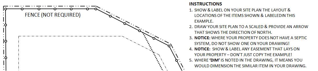
1. Draw an arrow over the property’s existing driveway and pointing into the lot. Label the arrow location as “construction entrance”; OR
2. Draw an arrow over a proposed alternate access location pointing into the lot. Label the arrow location as “construction entrance”. Also provide note required on the site plan of “A separate special use permit for a construction entrance will be obtained from the street right-of-way owner before the start of construction access to the project site”.
• Land Disturbance (SLCO Rev. Ord. LD106.3)
Get a separate Major Land Disturbance permit where any of the property’s proposed new work excavated and/or fill areas exceed 1 acre. This requirement applies to unincorporated areas and to municipalities contracting with St. Louis County for Land Disturbance enforcement.
• Licensed Electrical, Mechanical, and/or Plumbing (MEP) Contractors may sign on to a Residential Building Permit Application before it is approved and issued, as long as each trade’s proposed new work is provided in the drawings. An Integrated Permit allows a sub-contractor to sign-on to the building permit
• A Homeowner may perform Electrical and/or Plumbing new work ONLY if pre-authorized by passing a written test administered by St. Louis County Code Enforcement for either trade. The test is to demonstrate the Homeowner has the knowledge and ability to perform the work.
• All mechanical work must be performed by a licensed contractor authorized to do residential mechanical work. Homeowners may perform their own Mechanical work within their own dwelling with no requirement to be licensed. Sub-contractors are required to sign-on to the permit after it is issued.
• Structural alterations proposed to the existing building must be drawn and submitted as an electronic set and properly sealed by a Missouri registered Design Professional. Properly sealed structural calculations may also be required by the Plan Reviewer, depending on the alterations proposed and the adequacy and completeness of the sealed drawings submitted.
• Only alterations shown in approved and issued permit drawings shall be provided in the field. If the

Field Inspector finds otherwise, a separate permit application submitted with properly sealed structural drawings and calculations shall be required for review of the outside-work scope alterations.
• Properly sealed drawings means the first sheet of the electronic submitted set is electronically sealed, signed, dated by a Missouri registered engineer or architect, with subsequent sheets of set bearing the registered design professional’s electronic seal. The first sheet, or the title block of each sheet in each set submitted, is to note the design professional’s business address and contact number, and is to also include the project address, owner name(s) and a description of the new work proposed. Any revisions to drawings are to be highlighted by clouding or by another easily recognized method.
• Properly sealed calculations means the cover sheet shall be electronically sealed, signed, dated by a Missouri registered professional engineer or architect, with subsequent pages sequentially number and totaled, and starting with the cover as page 1. The design professional shall include on the cover his/her contact number and business address, as well as the project’s description of work, the project address and the property owner name(s); and shall provide in the calculations the Code Basis of Design.
• The Plan Reviewer may determine the proposed work, construction, or conditions require additional drawings and information be submitted to Code Enforcement-Plan Review for review, beyond the minimum submittal requirements noted in this Checklist.
Submittal Requirements: Construction-Ready Drawings, Their General Notes of Construction, & Zoning
• Provide the following for a permit to construct an Attached Garage in Unincorporated St. Louis County, or in those Municipalities that contract with St. Louis County for Residential Code Enforcement Services.
• Electronic Building Permit Application filled out, signed and dated by the applicant
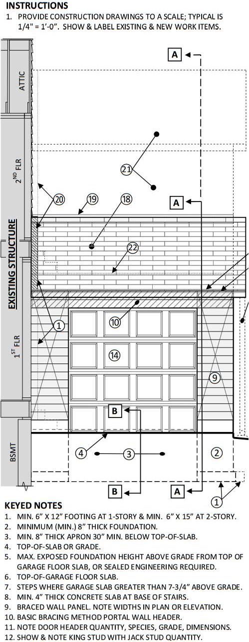
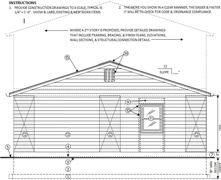
• Submit electronic drawing set provided at an architectural scale that are labeled and dimensioned and as noted below. Also submit other documents as noted (B107.2.1; SLCO Policy):
1. Site Plan for Zoning approval. For projects in a Municipality, submit electronic site plan(s) stamped, signed and dated by the Muni’s Zoning Officer, and submit the approved zoning application receipt signed and dated by the Zoning Officer. For properties located in Unincorporated St. Louis County, provide site plans with the following (SLCO Policy):
a. Draw lot configuration, dimension property lines, and show a North arrow Note the lot number and subdivision name. Label and dimension setbacks and easements. Show and name streets adjoining the lot.
b. Show and name existing dwelling and other structures on the lot, including retaining walls
c. Show and label the location of any existing septic/on-site sewage disposal system and/or well.
d. Show and size the new work Attached Garage. Dash-outline and dimension roof overhang projections more than 18”. Dimension distances from the Attached Garage to property lines and to other structures on lot Dimensions perpendicular to the property line(s).
e. Note finished grade heights at each corner of the Attached Garage, at lot corners, and at the driveway entrance from the street. Show with arrows the surface drainage direction around the Attached Garage. Show and label any swales (SLCO Policy).
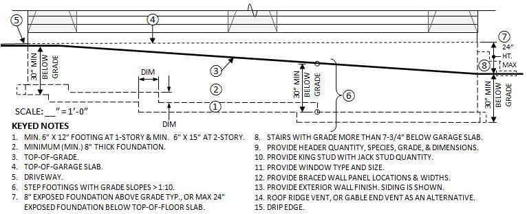
f. Show, dimension and label as new or existing the driveway from the street to the Garage. Identify the driveway material. Provide note the driveway and other proposed impervious surfaces within 10’-0” of the building foundation shall slope minimum 2% away from a building a or 1/4”:1’-0” (R401.3; SLCO Policy).
g. Note on the Site Plans: “Siltation and erosion control measures must be provided to prevent siltation/erosion from leaving the construction site” (SLCO Policy).
h. An Attached Garage proposed in a flood hazard area will go through a Floodplain Plan Review, which includes checking the height required of the garage floor above grade. Contact Floodplain Plan Review for more information (SLCO Rev. Ords. R322.1; R322.1.5; R322.2.1).
a. Architectural/Structural Drawings:
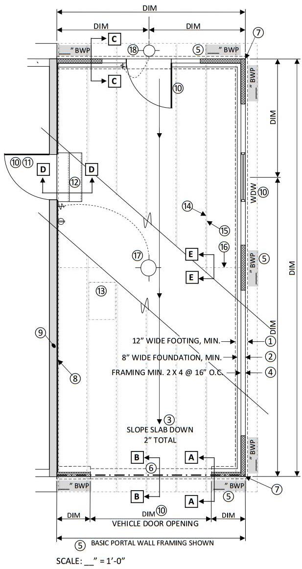
a. Footing/Foundation/Floor Slab Plan, 1/4” = 1’-0” typical;
b. Wall Framing/Interior Finish Floor Plan, including Electrical Layout, scale 1/4”=1’-0” typical.
c. Wall Bracing Plan. May be provided in the Floor Plans, with bracing method identified.
d. Roof Framing Plan, scale 1/4”=1’-0” typ.
e. Truss Drawings (SLCO Rev. Ords. B107.2.1; R502.11.1; R502.11.4; R802.10.1; R802.10)
1. Manufacturer’s Layout of Truss Assembly and Locations of Labeled Trusses
2. Truss Design Drawings properly sealed by a Missouri Registered Professional Engineer. Drawings must include required truss spacing and slope.
3. Sealed truss drawings may be obtained from a lumber dealer or the truss fabricator.
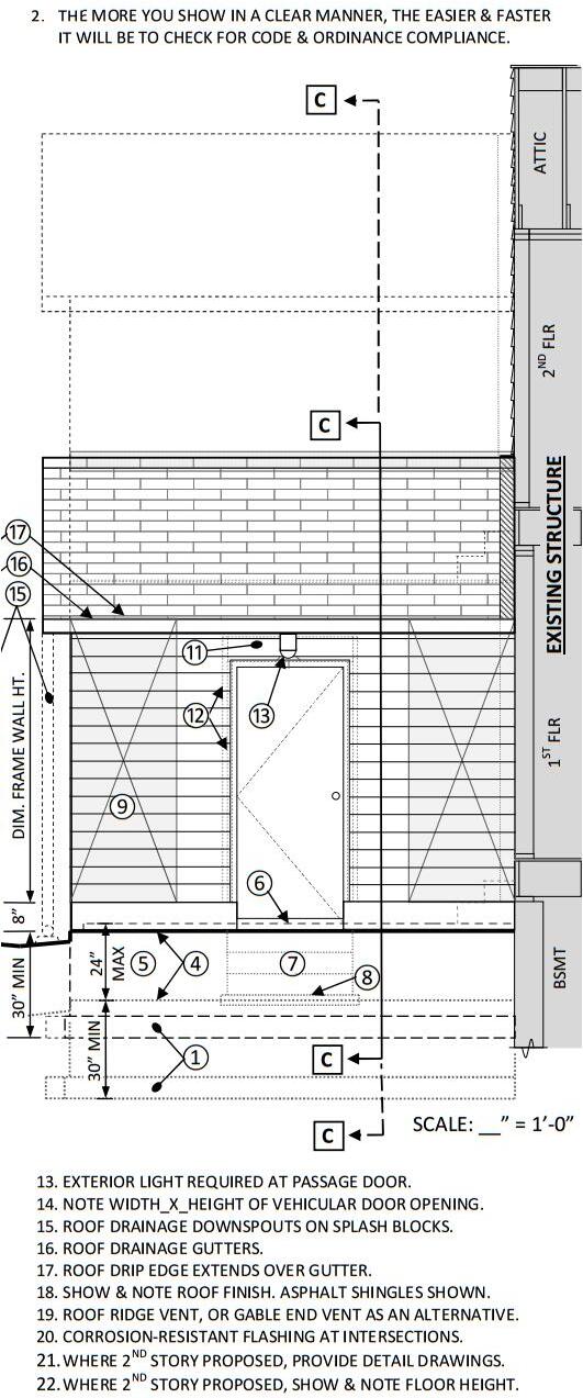
f. Roof Finish Plan with Flashing, Drip Edges and Roof Venting shown and labeled, 1/4”=1’-0”
g. Exterior Building Elevations Front, Rear and Sides, scale 1/4”=1’-0” typ.
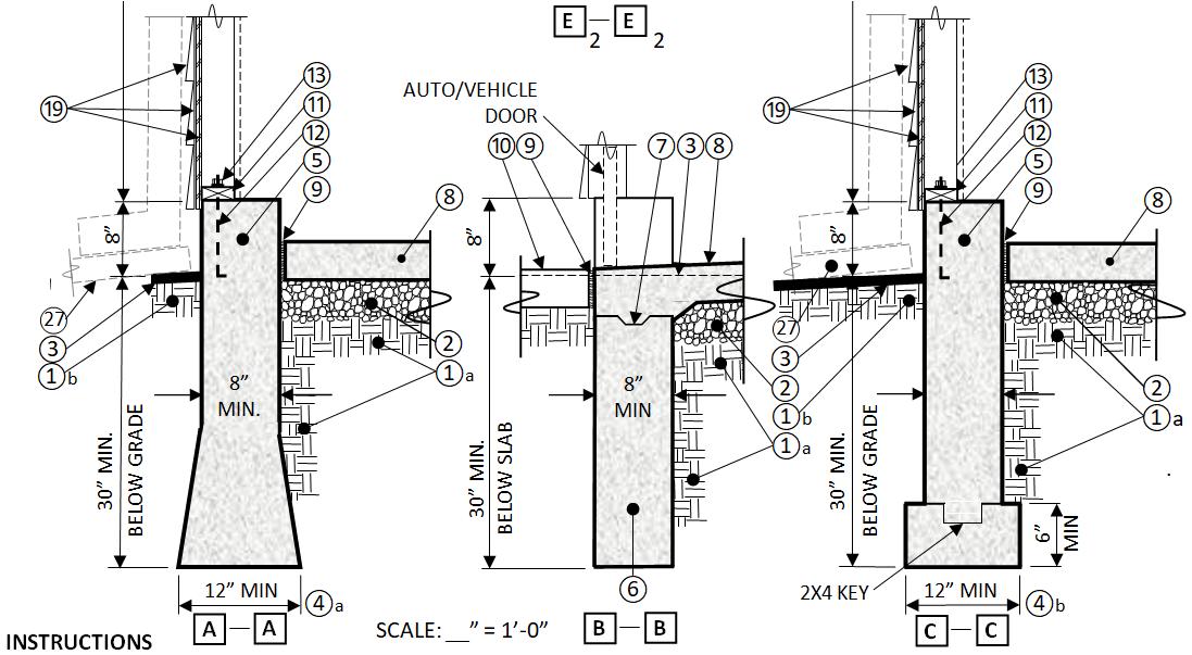
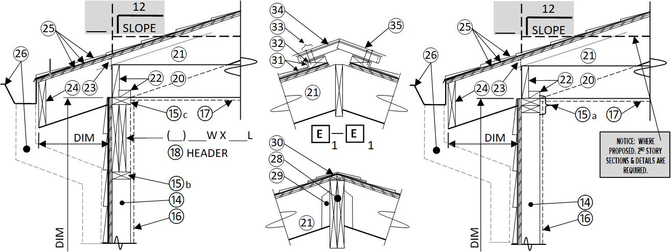
h. Wall Construction/Assembly Section(s), extending from Footing to Roof Finish and from exterior wall finish to interior finish. Dimension roof frame overhang and show venting Show minimum 4’-0” of the interior rafter/joist or truss framing/assembly/finish, scale 1/2” to 3/4”=1’-0” .
i. Construction/Assembly Details, including Wall Bracing details from a prescriptive method, Corner & Portal Framing, any required Bracing Hold-Downs, scale 1/2” to 1-1/2”=1’-0.

j. Electrical Layout Plan(s) – Show and identify electrical devices proposed, including receptacles, lights and switches.
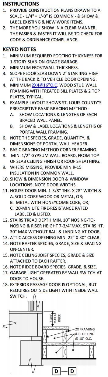
• See the example drawings at the end of this checklist for reference in completing your own projectspecific drawings. The lists below are Code and Ordinance requirements for a residential Attached Garage to be provided in your drawings and notes.
Design, Construction & Finish Requirements
Garage Separation from Dwelling
• Provide minimum 1/2" gypsum board on the garage side of the wall common to the dwelling. Show and note gypsum board shall extend from the top of the garage slab to the underside of the roof sheathing or ceiling finish (R302.6; Table R302.6).
• Where insulation is found missing in the residence/Attached Garage common wall, provide minimum R15 insulation in the stud wall cavities (N1101.5: N1101.5.1; SLCO Rev. Ord. Table N1102.1.2).
• Provide minimum 5/8” Type X gypsum board garage ceiling finish where a habitable room or story is provided above the garage (R302.6; Table R302.6).
• Provide minimum 1/2’’ gypsum board finish on garage bearing walls, beams, and columns that shall support the ceiling/floor assembly above (R302.6).
• Passage-door between garage and residence shall comply as follows:
1. 1-3/8’’ thick solid core wood door OR;
2. 1-3/8’’ thick solid or honeycomb core steel door OR;
3. 20-minute fire-resistance rated door.
4. Notice: Openings between a garage and sleeping room are prohibited (SLCO Rev. Ord. R302.5.1)
Concrete Footing/Foundation
• Minimum compressive strength is 2500-psi for footings and 3000-psi for foundations (Table R402.2).
• Minimum 8” thick continuous foundation that is air-entrained and extends at least 8” above outside grade. Exception: Foundation may extend 6” above grade where those sill plates and studs within 8” of grade are pressure treated (R317.1-Item 2; Table R402.2).
• Footings minimum 6” thick x 12” wide extending at least 30” below grade where only a roof/ceiling assembly with wood-frame walls of approved siding or brick-veneer finish is supported. See the SFD Guide Table or the 2015-IRC for footing sizes required to support other loading conditions (R301.2; R403; R403.1.4.1-Item 1; Tables R403.1(1)(2); SLCO Rev. Ord. Table R301.2(1); SLCO Policy)
• Notice: Garage foundations with more than 2’-0” of unbalanced backfill and parking surcharge must be designed by a Missouri registered design professional. Submit properly sealed electronic sets of structural drawings and set of calculations. Drawings shall include plans, sections, connection details, materials requirements, and construction notes and be scaled, dimensioned, labeled (B107.2.1; R301.1.3).
Concrete Floor Slab and Driveway
• Minimum compressive strength of the garage concrete floor slab is 3500 PSI and air entrainment is required (Table R402.2).
• Floor slab minimum 3-1/2” thick on a minimum 4” thick base course of gravel or crushed stone. Slope slab to direct surface fluids to the main vehicle entryway or to an approved drain (R309.1; R506; R506.1)
• Other garage floor materials proposed must be approved noncombustible, will maintain surface drainage and slope to direct surface fluids to the main vehicle entryway or to an approved drain (R309.1).
Sill Plate Anchorage
• Show and note in the exterior wall section(s) (R403.1.6):
1. Minimum 1/2" diameter anchor bolts spaced maximum 6’-0” o.c around entire foundation and placed in the middle 1/3 of the plate width
2. Anchor bolts extended 7” minimum into the foundation through the wood sill plate. Show and note each bolt fastens to the sill plate using 1-1/2" dia. washers with nuts.
3. Grout sill plate level or provide sill sealer with approved shim materials and methods.
4. An anchor bolt must be 4”-12” from the end of each sill plate segment.
5. Provide at least 2 anchor bolts per sill plate segment, regardless of the plate segment’s length.
6. Provide 2” x 2” x 3/16” square plate washers in place of 1-1/2” dia. washers to anchor bolts at sill plates (see item 1. above) located at any prescriptive Portal Frame Panel Construction (R403.1.6; R602.10.6; R602.11; R602.11.1; SLCO Policy).
Wood Wall Framing
• Provide minimum 2x6 studs #2 grade at 24” o.c. with a maximum 10’-0” wall height and 2-2x6 top plates.
Exceptions:
1. 2x4 exterior wall framing is allowed with roof spans 32’-0” maximum (R602.3; Table R602.3(5)).
2. Frame wall height may increase to 12’-0” where drawings identify and show St. Louis County’s Basic Bracing Method layout and its construction requirements (SLCO Rev. Ord. R602.13)
3. Frame wall height may increase to 12’-0” where drawings identify and show a prescriptive bracing method from the 2015-IRC and all of its adjustment factors that allow the height increase.
• For performance-based construction: Wall construction and the wood and wood-based products and
connections provided in drawings shall be structurally adequate to support the loads exerted on them, shall adequately transfer loads to supporting members, and shall comply with the 2015-IRC woodframing requirements. Drawings must be sealed by a Missouri registered design professional, and sealed calculations may be required with the sealed drawings (R301; R601; R602).
• Dimension the wall height from the bottom of the sole/sill plate to the top of the top plate. A tolerance of +/-2” is allowed, so a 10’-0” wall height drawn may be 10’-2” in the field (R602.3; SLCO Policy).
• Dimension the exterior grade as minimum 6” below the top of the foundation for exterior wood frame walls, and as minimum 4” below brick veneer on wood frame exterior walls. Note pressure-treated wood framing is required for members set on concrete or on masonry foundations less than 8” above exposed ground, and for all other wood less than 6” from the ground (R317.1; R404.1.6).
• Note wall opening widths. Show and note the size, quantity, and grade of wood headers and the quantity of their supporting jack studs. With masonry veneer, note the gage/thickness of lintels above openings (B107.2.1; R602.7; R703.8.3.1; Tables R602.7(1); R602.7(2); R703.8.3.1; SLCO Policy).
• Provide cutting, notching, and/or boring holes in wood beams, joists, rafters, or studs that meet 2015IRC limits (R502.8; R602.6; R602.6.1; R802.7)
• Fasten floor, wall, and roof frame assemblies in accordance with Tables R602.3(1) through R602.3(4). Fasten interior gypsum board in accordance with Table R702.3.5.
Wall Bracing
• Brace an Attached Garage to resist wind forces in accordance with SLCO’s (St. Louis County’s) Basic Bracing method guide provided with this checklist, or brace the attached garage in accordance with 2015-IRC prescriptive methods
• Using the SLCO Basic Bracing Method, show and label in the drawings the required braced wall panel locations and length of each. Show and label in the plans or elevations the locations of any required minimum 800# hold-down devices. Provide required bracing details (B107; B107.2.1; SLCO Rev. Ords. R107; R602.13).
• Using the prescriptive bracing provided by the 2015-IRC, identity in the drawings the bracing method(s) used and show in a layout. Provide details of a) the type of bracing; b) the bracing connections; c) the location and dimensioned length of each labeled braced wall line; d) the braced wall panel locations and length of each; e) the sum of the lengths of braced wall panels in each braced wall line and; f) the minimum required sum of the lengths of the braced wall panels in each braced wall line (SLCO Policy).
• The 2015-IRC’s prescriptive bracing methods for resisting lateral wind forces are for a maximum 10’-0” frame wall height; however, up to a 12’-0” height is allowed where the drawings show the 2015-IRC’s adjustment factors are applied. St. Louis County’s prescriptive Basic Wind Bracing Method allows a maximum 12’-0” frame wall height. Greater frame wall heights must be justified as structurally adequate in bracing drawings and bracing calculations properly sealed by a Missouri registered design professional (R301.3; R602.3.1; Table R602.3(5); SLCO Policy)
• Where walls are to be stacked (like a gable-end wall bearing on a frame wall below it) and NOT ballooned framed from the floor to the ceiling line, provide the following:
1. Floor-to-ceiling height is 12’-0” or less:
a. On the interior side, fasten together an exterior frame wall and the gable end truss or pony frame above it using minimum 16 gauge, 1-1/4” wide x 21” long metal straps spaced apart horizontally maximum 4’-0” o.c.
b. Fasten 10” of the strap to the stud below and the remainder of to the stud above. Use 9-16d nails to fasten the strap to the studs below and above, for a total of 18-16d nails in the entire strap.
c. Straps must be located at each end of the walls connected, or as close to the ends as space
allows for the strap length required for top and bottom studs.
d. Straps are prohibited from being bent horizontally to compensate offset wood framing. Instead, add 2x4/6 studs that align with the stud above or below and to both of which the straps attach
2. Floor-to-ceiling height is greater than 12’-0”: Submit properly sealed structural calculations that justify the tall braced wall and the building structure’s resistance to transverse loading (perpendicular to the wall). Also justify the structure’s resistance to longitudinal loading (racking, in plane with the wall), where the wall is not to be prescriptively braced using the IRC or SLCO methods referenced above, OR where the braced wall panels are located in that portion of the wall taller than 12’-0”
3. Provide 2” x 2” x 3/16” square plate washers in place of 1-1/2” dia. washers to anchor bolts at sill plates (see item a. above) located at any prescriptive Portal Frame Panel Construction (R403.1.6; R602.10.6; R602.11; SLCO Policy).
Fire-Resistant Construction
• Where all Dwellings in a subdivision are not sprinklered in compliance with NFPA 13D, the Attached Garage shall comply with the Table below for exterior walls and projections, openings, penetrations:
Exterior Walls (Without Sprinklers) – SLCO Rev. Ord. Table R302.1(1) below:
a. Fire-resistance rating of the roof eave underside is 0 hours where fireblocking is provided from wall top plate to underside of roof sheathing.
b. Fire-resistance rating of the roof eave underside is 0 hours where the eave that has NO gable vent openings.
• In a subdivision where all dwellings are sprinklered throughout in compliance with NFPA 13D, a Attached Garage shall comply with Table R302.1(2) of the 2015-IRC for exterior walls and projections, openings, penetrations (SLCO Rev. Ord. R302.1)
Finish Siding and Covering
• Exterior wall coverings, siding, backing materials, joint treatment and their attachment must resist wind loads, comply with code and the manufacturer’s requirements (R301.2; R703.3; Tables R301.2(2); R301.2(3); R703.3(1)).
Anchored Masonry Veneer
• Provide minimum 3/16" diameter weepholes maximum 33" apart placed directly above the flashing. Provide flashing between the masonry’s 1st course and the structure supporting the veneer assembly (R703.8.6).
• Maximum wall height is 30'-0” above the foundation and maximum 38'-0” measured to the top of a gableend wall (R703.8; Table R703.8(1))
• Anchor masonry veneer to wall studs with minimum No. 22 gage x 7/8” corrosion-resistant corrugated metal ties spaced maximum 32” o.c. horizontally [x 12” vertically = 2.67-sf] or maximum 24” o.c. vertically [x 16” horizontally = 2.67-sf]. Each tie shall support maximum 2.67 sq. ft. of wall. Provide 1” airspace between veneer and wall sheathing, or grout-fill the 1” space (R703.8.4; R703.8.4.1; Table R703.8.4).
• Provide openings greater than 16” in either direction in a masonry veneer wall with additional metal ties spaced maximum 3’-0” o.c. around and within 12" of the opening (R703.8.4.1.1).
• Masonry veneer over openings shall be supported typically on a steel angle shop-coated to inhibit rust and installed with the longest leg vertical. Lintels shall have 4” of bearing each end. Lintel size and gage required is based on opening width, veneer weight, and story height (R703.8.3; Table R703.8.3.1).
Adhered Masonry Veneer
• At frame walls, provide minimum 4” clearance above grade; min. 2” above paved areas; min.1/2” above exterior walking surfaces supported by the same foundation as the wall; OR as required by the manufacturer. Wood framing less than 8” from grade shall be treated (R703.12)
• At frame walls, provide at least 26-gage, corrosion-resistant metal or 0.019” plastic flashing or screed with a 3-1/2” vertical attachment flange extending at least 1” below the foundation plate (R703.12.2).
• Provide a water-resistive barrier lapping over the screed’s exterior flange or the flashing (R703.12.3).
Roof Frame Assemblies
• Label the roof/ceiling framing method as ridge board framing, ridge beam framing, or the truss method.
• Dimension roof overhangs in the roof framing plan or in the exterior construction/assembly sections.
• Show in plan and section roof rafters and ceiling joists framing and note member sizes, spacing, species, grade and/or fiber stress. Note a minimum 3:12 roof slope is required for the rafters and ceilings joists noted in Tables R802.4(1)(2) and Tables R802.5(1)-(9) in the 2015-IRC.
Notice: For roof framing slopes less than 3:12, submit gravity load and deflection calculations to justify structural adequacy of solid sawn framing and construction proposed Calculations may be required to be properly sealed by a Missouri engineer or architect (R802, esp. R802.2; R802.4; R802.5; Tables R802.4(1)(2); R802.5.1(1)-(9); Figure R802.5.1).
• Note cutting, notching, and/or boring holes in wood beams, joists, rafters shall meet 2015-IRC limits (R502.8; R802.7)
• Note roof frame assemblies must be fastened in accordance with Tables R602.3(1) through R602.3(3).
• Provide conventional roof framing and truss roof framing assemblies to resist uplift. Attach rafters and trusses to supporting wall assemblies in accordance with Table R602.3(1), where the roof assembly:
1. Is verified to have an uplift force not exceeding 200-lbs;
2. Has framing spaced not more than 24” o.c. and;
3. The roof overhang projects 24” maximum from the wall face below it.
• Nail trusses to the wall top plates with 3-16d nails toe nailed without splitting the end of the truss (R602.3; R802.11; Tables R602.3(1); R802.11; SLCO Policy)
• Approved roof tie-down anchorage (clips) is required for the first 8’-0”, measured from the corners of gable ends, and must meet capacity requirements of the 2015-IRC Table R802.11 per footnote d):
1. Roof pitch is less than 5:12, and roof span is more than 28’-4”; OR
2. Roof pitch is 5:12 or more, and roof span is more than 33’-3”.
• Provide roof framing that supports the following minimum loads:
1. Truss top chord or roof rafter:
a. Snow Load: 20 lb. per sq. ft. (R301.2; R301.6).
b. Dead Load: Include the weight of 2 layers of roof covering (R301.4; R908).
2. Truss Bottom chord or conventional framing ceiling joist:
a. Shall support a live load of 20-lb. per sq. ft. where attic storage is possible in a space where a
42” high x 24” wide rectangle can be placed perpendicular to the rafter/ceiling joists or trusses. Use 10 lb. per sq. ft. live load for no attic storage where rectangle-space dimensions are less.
b. Notice: The live load design on the ceiling joist or bottom chord of a truss shall not be required where all of the following conditions are met (R301.5; SLCO Policy):
1) Minimum 1/2” gypsum board at underside of ceiling joists or truss bottom chords.
2) Minimum 22”x30” attic access opening through the ceiling and no pull-down steps (R807.1)
3) On the attic side of the access opening, post warning signs at least 36" above the bottom chord and within 18" of the opening’s edge Each sign shall be min. 40 sq. in. metal or an approved durable material for attic conditions with 3/4" height letters on a contrasting background noting “WARNING-TRUSSES NOT DESIGNED FOR ATTIC STORAGE”
4) In the attic around the access opening over a garage with finished ceiling, provide a horizontal railing attached to the trusses on each side of the access opening 24" - 36" above the bottom chord. The railing shall be made of 1x4's, 2x4's or 3/8"x 6" plywood and shall obstruct easy access for storage Railing may be shop or field applied.
c. Dead Load: Use actual dead load (R301.4).
• Metal-plate-connected wood truss design and manufacture must comply with ANSI/TPI 1. Drawings shall note trusses shall be braced for lateral stability and to prevent rotation during construction and upon completion (R802.10.2; R802.10.3; SLCO Policy).
Roof Sheathing
• Provide the following for Wood Structural Panel (WSP) roof sheathing (plywood or oriented strand board-aka OSB), that has a maximum 24/0 span rating, and fasten to trusses or rafters spaced 24" o.c. (Table R503.2.1.1(1); R803.2.1; Ref. Std. APA Pub. N335P, D481):
1. WSP minimum 15/32” thick without edge support, OR
2. WSP minimum 3/8" thick with edge support, AND
3. WSP edge support shall be tongue-and-groove joints, 2x lumber blocking, or panel edge clips at the mid-point between each support.
Roof Cover, Slope, Underlayment, Flashing & Drip Edge
• Label all roof shingles as Class A, B, or C where any roof edge is less than 3’-0” from a lot line (R902.1).
• Notice: A minimum 3:12 roof slope is required to use rafters and ceilings joists noted in Tables R802.4(1)(2) and Tables R802.5(1)-(9) of the 2015-IRC.
• Provide at least Type I underlayment (15# felt) per ASTM D 226; D 1970; D 4869; or D 6757 (R905.1.1).
• Provide the underlayment for asphalt shingles as follows:
1. Provide a minimum roof slope of 2:12 for asphalt shingles. Minimum 2 layers of underlayment required on slopes of 2:12 to less than 4:12. Starting at and parallel with the eaves, fasten a 19” strip of underlayment felt. Starting at the eave, apply 36” wide sheets of underlayment. Successive 36” wide sheets of underlayment shall overlap the previous 36” wide sheet by 19”. Adequately fasten underlayment to hold in place (R905.1.1; R905.2; Table 905.1.1(2)).
Notice: roof framing member may require a minimum 3:12 slope.
2. Provide minimum 1 layer of underlayment on slopes 4:12 and greater. Apply underlayment shingle fashion, so it is parallel to and starting from the eave and is lapped 2”. Adequately fasten to hold in place. End laps shall be 4” and offset 6-ft (R905.1.1; Table 905.1.1(2)).
• Notice: An ice barrier underlayment is not required (R905.1.2; SLCO Rev. Ord. Table R301.2(1)).
• Provide corrosion-resistant flashing at roof intersections, changes in roof slope at walls and chimneys, around roof openings, and at abutments with porches and decks (R903.2; SLCO Rev. Ord. R905.2.8.2).
• Provide valley flashing in accordance with the manufacturer’s installation instructions before applying shingles The following valley linings are permitted (SLCO Rev. Ord. R905.2.8.2):
1. Open valleys (valley lining exposed) lined with metal: the valley lining shall be at least 24” wide and of any of the corrosion-resistant metals listed in the 2015-IRC Table R905.2.8.2.
2. Open valleys: valley lining shall be of 2 plies of mineral surface roll roofing, complying with ASTM D 3909 or ASTM D 6380 Class M. Layer widths shall be at least 18” on the bottom and 36” on the top.
3. Closed valleys (valley covered with shingles): valley lining shall be of 1-ply smooth roll roofing complying with ASTM D 6380, or 2-plys of smooth roll roofing complying with ASTM D 226 Type I, ASTM D 4869 Type I or ASTM D 6757 and at least 36” or valley lining as described in Item 1 or 2 above shall be permitted. Self-adhering polymer modified bitumen underlayment complying with ASTM D 1970 shall be permitted in place of the lining material.
• Provide a drip edge at eaves and rakes of shingle roofs. Extend drip edge minimum 2” onto roof sheathing and minimum 1/4” below roof sheathing. Install roof underlayment over the drip edge along eaves and under the drip edge at rakes (R905.2.8.5).
Roof Drainage
• Show and note gutters and downspouts on roof overhangs that project less than 36" (P1103.2; P1103.3; SLCO Rev. Ord. P1101.12.1; SLCO Policy).
• Show that storm drainage permitted to discharge onto flat areas, like lawns and streets, shall flow away from the Attached Garage and away from adjoining property, and shall not create a nuisance. Show that surface water drainage shall be directed to an approved water course or shall be piped to a storm drain. Notice: It is prohibited to discharge to or within 10' of a property line, sidewalk, driveway, street or to produce discharge that creates a nuisance to adjoining properties (P1101.2; P1101.11).
Roof Ventilation
• Show roof cross-ventilation of enclosed attic spaces or of enclosed rafter framing, where the vents open directly to outside air The minimum net free ventilating area is 1/150th of the area of the space vented (R806.1; R806.2).
• Roof cross-ventilation may be louvered vents in each of the opposing gable end walls, where the area being vented under the roof remains completely open. The minimum net free area of each louvered vent is half of the 1/150th area of the space vented (R806.2). OR
• Roof cross-ventilation may be soffit vents at the bottom, with box vents or a continuous vent at the roof ridge. Provide only 40%-50% of the openings at or near the roof ridge. The rest are to be provided at the roof soffits or eaves Show a minimum 1” continuous clear air passage is provided at the underside of the roof sheathing (R806.2; R806.3).
Smoke & Carbon Monoxide Alarms
• With a new work Attached Garage, the dwelling’s smoke and carbon monoxide alarm systems shall be verified as, or shall be made compliant with, 2015-IRC requirements as follows (R314; R315):
1. Smoke alarms AC powered and with battery backup, compliant with NFPA 72, and listed in accordance with UL 217 (R314.1; R314.1.1)
2. Smoke alarms are placed as follows (R314.3):

a. In each sleeping room between the room’s entrance and the bed.
b. Outside the sleeping room (in a hallway), in the immediate vicinity of the entry to each separate sleeping room and upstream from any return air grille.
c. On floor levels with no sleeping room or bedroom, such as basements and habitable attics.
d. On the upper level of a split level dwelling without a door between the levels and where the adjacent lower level is less than 1 full story below the upper level.
e. On both levels of a split level dwelling where a door intervenes between the levels, or where the levels are 1 full story apart.
3. Where more than 1 smoke alarm is required within a dwelling unit, the alarm devices are interconnected so activation of 1 alarm will activate all alarms throughout the dwelling unit (R314.4).
4. A carbon monoxide alarm outside of each separate sleeping area and near the bedrooms in a dwelling with a fuel-fired appliance or with an attached or basement garage (R315.2; R315.3).
5. A carbon monoxide alarm in a bedroom in the space between a bed and the fuel-burning appliance, including appliances in a bathroom that opens to the bedroom (R315.3).
6. Carbon monoxide alarms shall be shall be AC powered with battery backup and be listed per UL 2034. Combination carbon monoxide/smoke alarms shall be listed per UL 2034 and UL 217 (R315.1.1)
Electrical Requirements
Electric power in an Attached Garage is required Electric shall comply with the following:
• Show in the plans the keyed or labeled locations of lights, switches, and receptacles. Use a curved line to link each switch to the light(s) and/or receptacles they control (B107.2.1; SLCO Policy)

• Show ground-fault circuit-interrupter (GFCI) protection is provided for each 125 volt, single phase, 15 and 20 ampere receptacle in the garage, with a receptacle provided 5’ -6” maximum above the floor at each bay (E210.52(G)(1); SLCo Rev. Ord. E210.8(A)).
Exception: GFCI protection is not required for the garage door opener’s ceiling-mounted receptacle.
• Automatic overhead garage door openers shall be listed and labeled per UL 325 (R309.4).
• Provide at least 1 interior lighting outlet that is controlled by an interior wall-switch near the house entry door (E210.70(A)(1)).
Exception: Remote, central, or automatic control of lighting is allowed for interior lighting of an Attached Garage
• Provide at least 1 wall-switch-controlled lighting outlet on the exterior side of a passage-door with grade level access. Place the wall switch on the inside of the garage near the passage door. The vehicle door may be considered as an exterior entrance or exit (210.70(A)(2)(2)).
Exception: Remote, central, or automatic control of lighting is allowed at outdoor entrances.
• Provide a storage attic in an Attached Garage with 1 lighting outlet that contains its own switch, or is wall-switch-controlled. The lighting outlet controls must be at the entry to the attic space (E210.70(A)(3))
Notice: The preceding requirements apply to most simple Attached Garages on the properties of single-family dwellings. However, the Plan Reviewer may determine the actual new work shown in the drawings requires additional information be submitted to verify Code compliance of the new work proposed. The above requirements are based on the construction codes in effect at the time this checklist was last updated. Please be aware St. Louis County Code Enforcement updates its construction codes every few years.