
Residential In-Ground Swimming Pool & In-Ground Spa Checklist & Guide for a Building Permit
(An Abridged Summary of 2015 IRC Requirements
As Amended by St. Louis County Ordinances
This Residential In-Ground Swimming Pool Checklist is based on St. Louis County’s (SLCO) policies, construction codes amended and adopted by ordinance. See list below. It is not a substitute for those codes and ordinances, but serves as a guide to reading them. More information and explanation is provided in commentaries and interpretations published by St. Louis County and acknowledged code organizations.
List of Applicable Codes and Ordinances:
2015 International Swimming Pool & Spa Code (ISPSC) & Ordinance #27,654-Ch.1118 (“SP” refs.)
2015 International Residential Code (IRC) & Ordinance #27,654-Ch.1116 (“R” “G”, “N”, and “M” references and Appendix K - Sound Transmission)
2015 International Building Code (IBC) & Ordinance #27,654-Ch.1116\5 (“B” references).
2014 National Electrical Code (NEC) aka NFPA 70 & Ordinance #27,430-Ch.1102 (“E” refs).
2015 Uniform Plumbing Code (UPC) & Ordinance #27,424-Ch.1103 (“P” references).
For inquiries regarding the information provided in this checklist, please contact:
(314) 615-5485
St. Louis County Permit Processing (314) 615-5184 St. Louis County Zoning Review (314) 615-3763 St. Louis County Building Plan Review

Right-of-Way Owner State
(888) 275-6636 County
(314) 615-8517 Municipality
Call the project site’s Municipality
St. Louis County’s Municipal Contracts Matrix shows those municipalities that currently contract for its Code Enforcement services. The Matrix can be found on our web site at https://stlouiscountymo.gov/st-louis-county-departments/transportation-and-publicworks/residential-building/
For the electronic plan review, scan QR code or visit us online at https://stlouiscountymo.gov/st-louis-county-departments/transportation-and-publicworks/electronic-plan-review/
Sections from the Codes, their Referenced Standards, and St. Louis County Ordinances, are shown at ends of statements and are italicized in parentheses (.).

NOTICES Regarding Permits
• This Checklist provides basic information for a permit to construct an in-ground swimming pool or inground spa. Such a permit is required where:
1. Water depth is 24” or more, or;
2. The wall depth is 26” or more, or;
3. The volume of the water body container exceeds 5,000 cubic feet (SLCO Policy).
• The applicant (property owner or the Contractor) is responsible for contacting those agencies that may be affected by the new work, or that may have legal oversight of the new work along with but separate from St. Louis County. Where requirements among the agencies conflict, the most restrictive shall govern the new work. Contact these agencies before beginning work approved under a permit issued by St. Louis County. Such agencies may include:
1. The project site’s Municipality.
2. The Local Fire Protection District.
3. The Electrical Company
4. The Sewer District.
5. The Subdivision Trustees.
• Electrical, plumbing, and mechanical work must be performed by licensed and bonded electrical contractors, master plumbers, and licensed contractors authorized to do mechanical work. Each contractor must sign the permit application form in the appropriate location. Signatures must be provided to Public Works before the permit can be issued.
• Permit issuance for the project does not automatically authorize construction access to that project site. If a project site’s driveway entrance is unavailable for construction access or none exists, the property owner or authorized Contractor must apply for a permit with the Owner of the Right-of-Way (may be the County’s Highway Dept. or the Municipality) to construct a temporary entrance.
• Project-specific site plans submitted with the permit application should include the following:
1. Draw an arrow over the property’s existing driveway, and point it into the lot. Label the arrow as “Construction Entrance”; OR
2. Draw an arrow over a proposed alternate access location, and point it into the lot. Label the arrow as “Construction Entrance”. Note on the site plan: “A separate special use permit for a construction entrance will be obtained from the street right-of-way owner before the start of construction access to the project site”.
• The Plan Reviewer may determine the proposed work, construction, or conditions require additional drawings and information be submitted to Code Enforcement-Plan Review for review, beyond the minimum submittal requirements noted in this Checklist.
Submittal Requirements: Zoning Approval, Construction-Ready Drawings & Their General Notes of Construction

• Swimming Pool Permit Application – fill it out, sign and date If the in-ground pool or in-ground spa is to be heated (which is optional), note it in the ‘Work Description’ box.
• Zoning approval of the proposed new work must be provided with the permit application as follows:
1. Where the property is in a Municipality: Submit an electronic set of site plan that have each been stamped-approved, signed and dated by the Municipality’s Zoning Officer. Also submit the receipt to the completed zoning application form that has been approved, signed and dated by Muni’s Zoning Officer (B107.2.5; SLCO Revised Ord. R107.1)
OR
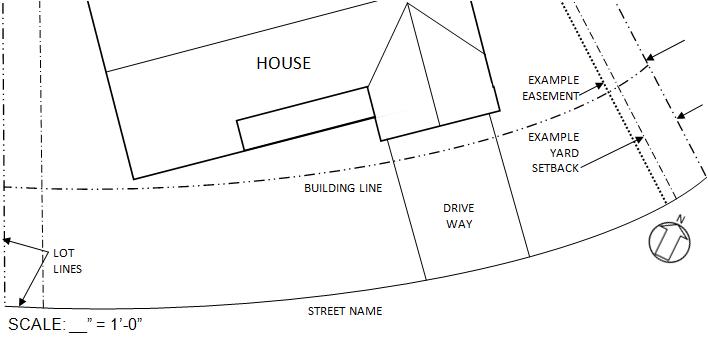
2. Where the property is in Unincorporated St. Louis County: Submit an electronic set of site plan drawn to a scale that include the following information:
a. Lot lines drawn. North arrow provided. Dimension and label any setbacks and easements. Show and name adjoining street(s). Note the drawing scale
b. Show and name the existing buildings on the lot.
c. Show pool location, size and note dimensions.
d. Dimension perpendicular to lot lines and buildings the pool’s distance from each of them.
e. Show and label the locations of the pool barrier(s) proposed, barrier/fence material(s) and height, and show gate locations.
f. Where applicable, show location/area of existing septic system.
g. Notice: properties with septic systems will require review and approval by Plumbing Inspections before the permit will be issued.
h. Notice: properties in a Flood Hazard Area will require flood plain plan review and approval of the pool and its location before the permit will be issued (SLCO Revised Ord. R322.1).
3. Submit the items listed under 3.a. or 3.b. noted below, along with the site plans and permit application. Drawings submitted must be to a scale, fully dimensioned, and labeled (SLCO Rev. Ords. R107.1; B107.1 & SLCO Policy):
a. Provide the Master Plan number on the permit application in the ‘Work Description’ box for the new work construction of an in-ground pool and/or in-ground spa proposed on residential property.
Notice: Pre-approved pools each have a unique Master Plan number assigned to them by St. Louis County Code Enforcement. Your local pool contractor or supplier may have had their sealed pool drawings and documents already reviewed and pre-approved so a permitapplicant may more easily obtain a permit. Check with your pool contractor or supplier for such an in-ground pool and/or in-ground spa Master Plan number. OR
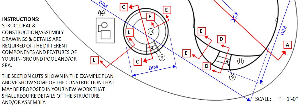
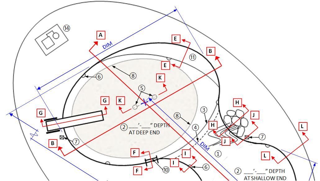
b. Provide a complete electronic set of detailed pool construction drawings, notes of construction and specifications, all prepared and properly sealed, signed, and dated by a Missouri Licensed Architect or Professional Engineer. The drawings must be to a scale, fully dimensioned and labeled, and contain at least the following:
1) Foundation/Structural Wall Plan.
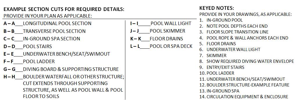
2) Long and Transverse cross-sections through the pool. In the sections, show and note the slope of sidewalls and floor, and note the water depth(s) throughout.
3) Assembly/construction section and plan details of pool/spa structural supports and structural reinforcing; pool/spa drains; skimmers or gutters; pool/spa filters; underwater luminaires in pool/spa structure; entry/exit ladders; entry/exit stairs/steps; features including underwater benches, seats, swimouts; diving boards; boulder waterfalls, where section extends through supporting structural reinforced slab, pool wall and pool floor (properly sealed, signed, dated structural calculations shall also be required)
4) Water supply system diagram(s); water circulation/filtration system diagram(s); drainage and water disposal system diagram(s)
5) General notes of construction and materials specification notes.
6) Where the drawings submitted have the affixed dated seal and signature of more than one registered design professional, such documents shall not be accepted for review without each professional having provided a written explanation of design responsibility on the drawings next to his/her seal and signature
7) Multiple seals from different states for the same design professional are accepted on the drawings where the design professional’s valid Missouri registration seal is provided among them
8) Each sheet of the swimming pool construction drawings subsequent to the firs/top sheet must bear the mechanically reproducible seal of the Missouri Registered Design
Professional. The first/top sheet of the electronic set must be electronically sealed and dated and signature
a. Grounding, Wiring, Receptacles, Lights – Submit plan layouts and electrical wiring diagrams that have been sealed by the Missouri registered design professional
b. Heating Pool/Spa/Hot Tub (optional) – Submit system design drawings and diagrams and installation requirements. Submit the manufacturer’s installation manual. Provide in drawings the requirements for the equipment pad (SP302.8.1; M2006.2)
c. Pool barrier drawings – Submit elevation and section drawings with construction/assembly members shown and labeled with materials and sizes shown and noted. Show and note gate requirements.
See the example drawings in this checklist for requirements to be provided. Be aware your drawings may need to provide more than is noted, depending on the work proposed and site conditions.
Design, Construction & Finish Requirements Drawings Content
The list below of required items - and those feature items where proposed as new work - are to be provided in sealed drawings for the following in-ground pool and in-ground spa types:
• Concrete - Gunite or Shotcrete Pool and/or Spa.
• Metal Frame with Vinyl Liner Pool and/or Spa without an evaluation report. Sealed structural calculations required.
• Fiberglass Pool and/or Spa without an evaluation report. Sealed structural calculations required.
Grades around Pool
• Surrounding grades shall be made to prevent surface water from entering the pool or spa. Any grade alterations to the area’s the existing stormwater drainage pattern must not be made without the prior approval of the Department of Highways and Traffic and Public Works
Pool Slopes
• Wall Slope shall be a maximum 5:1 = 5 units vertical for every 1 unit horizontal. Start the slope at the top of the wall and extend it to the wall-to-floor transition. The wall-to-floor transition shall be at least 2’-9” below the design waterline (SP308.2; SP805).
• Wall-to-Floor Transition shall be radiused or shall intersect at an angle. At water depths 3’-0” or less, the transition radius shall be 6” maximum and must be tangent to the wall (SP308.2).
Wall & Floor of Pool & Spa:
• Water depth at the Shallow End shall be 2’-9” minimum and 4’-0” maximum (SP807.2):
• Floor Slope at the Shallow End shall be 1:7 = 1 unit vertical for every 7 units horizontal, and shall slope toward the deep end of the pool (SP807.1.1; SP807.2):
Exceptions:
1. Beach and Sloping Entries are not limited to a 1:7 slope (SP807.2; SP809.6).
2. Steps and Sloping Entries are not limited to a 1:7 slope (SP807.2; SP809.7).
3. Surfaces of Architectural Features – like a vanishing edge wall - shall not be limited to a slope of 1:7 (SP807.2; SP809.8)
• Floor Slope Transition Point (really the line between 2 slopes having different inclines) between the shallow and deep ends shall have a 4’-0” maximum water depth at the shallow end, and shall be at least 6’-0” from the beginning of the shallow end (SP308.1; SP807.1.2).
• Floor Slope at Deep End shall be maximum 1:3 = 1 unit vertical for every 3 units horizontal, starting

at the Floor Slope Transition Point/line (SP308.1; SP807.1.3).
Life Safety Items
• Entry/Exit must be provided:
1. In the shallow area of a pool.
2. In combination as stairs, step(s), tread(s), ladder, ramp, beach entry, underwater seat, bench, swimout, or other approved designs (SP809.2).
3. In pool areas having a depth more than 5’-0” (SP809.3).
4. On both sides of the deep area of a pool more than 30’-0” wide (SP809.4).
• Pool Stairs extending out into the pool shall have (SP809.5):
1. Tread surfaces that are slip resistant, cleanable, and not an abrasion hazard (SP202; SP306.2).
2. Tread depth that is minimum 10” horizontal with an unobstructed surface area of 240 sq. inches; this means a 10” tread depth has a minimum 24” clear width (SP809.5.1).
3. Riser heights measured at the horizontal centerline of the stairs (SP809.5.2).
4. Top and bottom riser heights that may differ, but shall each be 12” maximum (SP809.5.2).
5. Intermediate risers with a uniform riser height that does not exceed 12” (SP809.5.2).
6. Steps that are not required below a water depth of 48” (SP809.5.3).
• Pool Stairs recessed from the pool wall shall have (SP322.4):
1. Tread surfaces that are slip-resistant and are not an abrasion hazard (SP202)
2. Uniform tread depth and be minimum 5” deep and minimum 12” wide.
3. The top tread 12” maximum below the adjoining surface of the pool deck and/or coping edge
4. Recessed treads with a uniform vertical spacing of at least 7” and not more than 12” measured at the stairs centerline (SP322.4.1).
• Pool Ladders shall have (SP322.3):
1. Tread surfaces that are slip-resistant and not an abrasion hazard (SP202).
2. Tread depth that is minimum 2”.
3. The top ladder tread 12” maximum below the adjoining pool deck or coping edge
4. A uniform distance of at least 7" and not more than 12" between each ladder tread
• Handrails or Handholds shall be provided on each side of pool ladders & pool recessed stairs, and shall have a clear distance apart of 17” to 24” (SP322.3.2; SP322.4.3).
• Handrails shall extend into the pool and shall be provided with (SP323.2):
1. An outside diameter that is 1-1/4” minimum or 2” maximum (SP323.2.5).
2. A top gripping surface 30”-38” above the step nosing or a sloped walkable surface (SP323.2.1).
3. Its leading edge 18” maximum from the bottom riser of pool stairs (SP323.2.4).
4. An installation that makes the handrail not removable without the use of tools (SP323.2.3).
5. Materials that are corrosion-resistant (SP323.2.2).
• Handholds shall be provided along the pool’s perimeter at 4’-0” on-center maximum and 12” maximum above the design waterline, where pool depth is more than 42” below the design waterline. Ladders, stairs, underwater seats, ledges, decking, coping, and permanently fixed rocks are considered handholds (SP323.1; SP323.1.1; SP323.1.2; SP323.1.3).
• Rope-&-Float shall be anchored to pool walls and provided across the width of the pool above and on the shallow-end side 1’-0” to 2’-0” from its slope break line (transition point). Anchoring devices shall be permanently fixed to pool walls, and the rope ends shall be made to disconnect from the anchoring devices... A Rope-&-Float is not required for pools with a constant or gently curving slope (SP811.1).
Underwater Features are Options, but must be code-compliant where provided:
• Underwater features include seats, benches, swimouts, and offset ledges (SP809.9).
• Underwater seats, benches and swimouts shall have horizontal surfaces that are 20” maximum below the design waterline (SP809.9).
• Offset ledges shall be 8” wide maximum where located 42” or more below the design waterline
(SP202; SP806.1):
• An offset ledge located above the 42” depth shall have its width reduced as follows (SP806.2): Ledge Width = Water Depth x 0.194 (the tangent to an 11-degree wall slope or 0.19-rad).
Above-Water Features are Options, but must be code-compliant where provided:
• Pools proposed with diving equipment shall be shown in sealed drawings to accommodate the form and minimum required area and depths for a diving water envelope (SP804.1: SP808.3; SP808.6; SP808.8; SP808.9; SP808.11; Table SP804.1; Figure SP804.1):
1. The Pool Type proposed – as listed in the 2015-ISPSC – shall be noted in the drawings.
2. Minimum water depths, slopes, and length and width dimensions of the pool shall be provided in sealed drawings of plans and longitudinal and transverse pool sections to show and note accommodation of the diving water envelope.
3. Pool entries/exits and pool features – such as stairs, ladders, underwater benches, swimouts –must be shown and noted as located outside of the minimum required diving water envelope (SP808.7).
• Diving Board, Springboard, or Jump Board: Provide the manufacturer name and model number in/on the sealed drawings. Show and dimension the minimum headroom clearance above the board tip as required by the manufacturer (SP808.13).
• Diving Platform, Rock, or Similar: Show and dimension the maximum height above the design waterline. The maximum height shall be based on pool type identified in the sealed drawings, and shall comply with the limits noted in Table SP808.12 (SP808.10; SP808.12).
• Slides: Note the manufacturer name and slide model number(s) in/on the sealed drawings. Note the slide(s) shall be provided in accordance with the slide manufacturer’s installation manual. Submit complete electronic set of the slide manufacturer’s installation manual (SP809.1).
On-Grade Decks & Walkways Adjoining a Pool/Spa:
• Deck surfaces and pool/spa coping shall be slip resistant and cleanable. Edges shall be radiused, tapered, or otherwise made without sharp corners (SP306.2; SP306.8).
• Deck surfaces shall be of the materials listed below. Other materials proposed require review and comment or approval by the code official. Decks and walkways shall be sloped to prevent surface drainage into the pool (SP306.5; SLCO Rev. Ords. SP306.1; Table SP306.5 below):
DRAINAGE SLOPES FOR IN-GROUND POOL OR SPA DECK SURFACES
• Wood or plastic composite pool deck boards shall have gaps provided between them. The gaps provided shall be consistent with approved engineering methods for the type of wood used, and shall not produce a tripping hazard (SP306.6).
• Concrete deck isolation joints, required at pool/spa coping, must be water-tight and provide for movement to protect coping and its mortar bed. Isolation joint may be 1/4” – 1/2” wide where compressible foam is covered with a flexible caulk (SP306.7; SP306.7.1).
• Decks of paved, concrete or unpaved surfaces that extend out from the pool or spa perimeter for a distance of “3’-0” measured horizontally from the inside face of the in-ground pool wall shall be
bonded. See the Section in this Checklist titled “Grounding, Wiring, Receptacles & Lighting Requirements”.
• Pool deck access stairs outside of the pool or spa basin shall have (SP306.3):
1. A uniform riser height;
2. A riser height shall be not more than 7-1/2”;
3. A tread depth front to back shall be at least 10”.
Glazing - Existing or New Work
• Glazing that is within 5’-0” measured horizontally of the water’s edge of a pool or spa, and is less than 5’-0” above a walking surface, shall be verified as, or made compliant with, the safety glazing requirements of the 2015 International Residential Code (SP307.2; R308; R308.4.5).
Some of the following code requirements for in-ground pools and spas are verified through the Inspections process of the pool and barrier installation, and may not be shown fully in the drawings.
Pool Barriers
Notice: Show and note the type, location, and height of the pool enclosure barrier(s) on your site plan. Drawings submitted must include an elevation drawing showing both gate and fence, and a sectional drawing of the fence/gate enclosure.
• Notice: For requirements noted in detail, see the 2-page list titled ‘Pool Barriers’ provided near the end of this Checklist. Below is only an overview.
• A code-compliant barrier is to prevent small children from entering the pool area unsupervised, and is to make pool/spa access difficult for unauthorized use.
• Pool barriers may be fences constructed of horizontal and vertical members. Spacing between the members is limited, depending on the distance between the horizontal members.
• Pool barrier enclosures may be of chain link with a maximum opening of 2-1/4” square, but the openings have to be reduced with slats to an opening of not more than 1-3/4”.
• Gates are allowed in pool barrier enclosures where gate latch height requirements are met

• House walls with openings having direct access to the pool must have sound alarms that activate when opened; OR passage doors to the pool must meet the requirements noted in the ‘Pool Barriers’ list; OR the pool is provided a Code-compliant cover.
• Caution: Pool barrier enclosures erected in a utility easement may be removed at any time by the easement holder. Obtain the easement holder’s approval before construction within the easement area or near utility structures, like storm water inlets, manholes, electrical and cable TV boxes.
Circulation Systems & Freeze Protection Requirements
Provide the following minimums. Check Codes and Ordinances for compliance with all requirements. Energy Conservation: The Homeowner and Contractor are to commit to Energy Conservation by providing low-energy pool appliances, such as motors and pumps (SP303.3; Ref. Std. APSP-15).
Circulation/Recirculation Systems
• Pumps and motors:
1. Location must be accessible for inspections and service and in accordance with their manufacturer’s instructions (SP704.7.2).
2. Have accessible shutoff to suction and discharge piping to service or remove pump (SP704.7.3).
3. A ground fault circuit interrupter must be installed in the electrical system for underwater lighting fixtures or cord connected pumps.
• Turnover (SP704.4):
1. Once every 12 hours.
2. System flow shall not be more than the filter manufacturer’s maximum filter flow rate.
• Surface skimmers:
1. Where serving as the pool’s only outlet system, provide 1 surface skimmer for every 800 sq.ft. or fraction thereof of water surface area (SP704.9.1).
2. Shall be made to skim the pool surface where the water level is maintained between the minimum and maximum fill level of the pool (SP704.9)
• Circulation/Recirculation Systems shall maintain clear, sanitary pool/spa water with no or few dead spots and shall remove, filter, treat surface water and return it cleansed to the pool/ spa. The system is typically made up of Surface Skimmers; Outlet Fittings; Strainers; Valves; Meters; Pump(s) with Motor(s); Filters; Heaters (optional); Gages; Chemical Feeding Devices; Inlet Fittings; and Piping connecting all (SP311; SP810; SLCO SP801.2; SLCO Rev. Ords. SP311.4; SP311.9).
1. The circulation system shall turn over pool/spa water once in not more than 12 hours. Determine the design flow rate required, assuming a filter in clean media condition with an adequate flow rating, and using the required turnover rate of the pool/spa water. A pool and spa may use the same circulation system equipment as long as they are adequately sized to accommodate both volumes (SP311.2.1; SP311.2-Exception; SP810.1).
2. Provide filters with a flow rating equal to or greater than the pool’s design flow rating. Filters provided shall allow for inspection and servicing of their filtration surfaces (SP312.1; SP312.2).
3. Piping subject to freezing, plastic piping and fittings, and fittings and joints used in the pool/spa circulation system shall be provided in compliance with the 2015 Uniform Plumbing code (SLCO Rev. Ords. SP311.4; SP311.4.1; SP311.4.2; SP311.4.3).
4. Circulation system equipment and exposed face piping shall be drainable by providing removable drain plugs, operable valves, or by other approved methods (SLCO Rev. Ord. SP311.5).
5. Locate and anchor the circulation system equipment, such as pump(s), motor(s), and filter(s), to be accessible for inspection and service, and as required by their manufacturer’s specifications and installation instructions (SP311.2.3; SP313.4).
6. Provide 1 return inlet for every 300-sq. ft. of pool surface area and fraction thereof (SP314.4).
• Skimmers provided as part of the pool/spa circulation system comply as follows (SP315.1; SP315.2):
1. Provide an automatic surface skimmer every 800-sq. ft. of maximum pool water surface area, and every 150-sq. ft. of spa water surface area (SP315.3; Table SP315.3).
2. Provide a perimeter-type skimmer, also called a gutter, on at least half of the pool or spa perimeter. The gutter system shall have a surge capacity of 1-gallon of water for every 1-sq. ft. of pool or spa surface water served (SP315.4; SP315.4.1).
3. Skimmer design and installation shall not provide a hazard to the user (SP315.6).
4. Skimmers shall be vented to the atmosphere through openings in the lid or through a separate vent pipe (SP310.1; Ref. Std. APSP 7-2013 Section 4.5).
5. Notice: An equalizer on a skimmer is prohibited (SP315.5).
• Where fully submerged suction outlets and suction-limiting systems are proposed for an inground pool or spa, provide the following (SP310.1; Ref. Std. APSP 7-2013 Section 4.4):
1. Notice: Submerged suction outlets are optional. Surface skimmers or overflow (gutter) systems are allowed to provide 100% of the pool/spa water circulation flow (APSP Section 4.4.1).
2. Comply with the requirements of APSP-16.
3. A single outlet shall be unblockable and have a flow rating equal to or greater than the maximum potential flow (APSP Sections 4.4.3; 4.4.9).
4. Multiple outlets shall be unblockable with a combined flow rating equal to or greater than the maximum system flow (APSP Sections 4.4.4; 4.4.9).
5. Suction outlet fitting assemblies and systems shall be certified (APSP Sections 5.3; 4.3.1).
6. Dual outlets that are blockable and in parallel to a single suction line shall comply as follows:
a. The centerlines of the 2 suction outlet covers or grates are placed apart 3’-0” minimum.
b. Each outlet is located on a separate plane, as on 2 separate walls or on a wall and a floor.
c. The outlets are not located in seating areas.
7. Water velocity in branch piping to at least 2 suction outlets shall be maximum 3-ft per second, with a maximum velocity of 6-ft/sec. if 1 of the 2 suction outlets is blocked (SP310.1; SP704.8; Ref. Std. APSP 7-2013)
8. Water velocity between the branch piping tee and the pump shall be maximum 8-ft per second (SP310.1; SP704.8; Ref. Std. APSP 7-2013)
9. The tee serving the branch piping between 2 or more suction outlets on a pump system shall be placed so the head loss in each branch run is essentially equal (SP310.1; SP704.8; Ref. Std. APSP 7-2013).
• Provide entrapment avoidance means on suction outlet fittings and assemblies as follows:
1. Comply with the UPC-2015 (SP310; SP314.2; SLCO Rev. Ord. SP311.4; SP311.4.1; SP311.4.4).
2. Manufactured suction outlet fitting assemblies shall be certified by a 3rd party test lab accredited by ILAC to test and certify products as conforming to ANSI/APSP-16 (APSP Section 4.3.1.1).
3. Field-fabricated suction outlet fitting assemblies shall be certified as conforming to ANSI/APSP-16 by a Missouri registered design professional (APSP-16 Section 4.3.1.2).
• Water Supply: A hose bibb used to fill the pool shall be protected by an approved backflow prevention device (vacuum breaker) or by an air gap between the filling hose and pool. ALicensed Master Plumber must install the approved backflow prevention device on the supply piping.
• Draining the System: Circulation system equipment shall drain water from equipment and piping by taking out drain plugs and manipulating valves, or as approved by the manufacturer (SP704.3).
• Discharge Water (801.1; P801.2; P803.1; P813; SLCO Rev. Ords. SP302.6; SP3201. P803.3):
1. Discharge to a location that shall not create a nuisance to adjoining property.
2. Flow into the storm sewer system only Connection to the sanitary sewer system is prohibited
3. Pass through a minimum 1” air gap or air break before entering the storm sewer system.
4. Water is pumped out through a hose to discharge onto a street curb that drains to a storm sewer
Requirements for Optional Heating of an In-Ground Pool or Spa
Show and note the following where pool heating is proposed as part of the new work. The listing below is only some of the Codes’ requirements for heating pools. Check the Codes for all requirements to be met.
• The pool/spa heating system and any gas line installation must comply with the manufacturer’s installation instructions and both the 2015 ISPSC and the 2015 IRC’s Chapter 24, Sections G2410 through G2424 and Section G2441 (both Codes are listed on page 1) The more restrictive requirement governs (SP102.7.1; SP316; SP316.4; M2006; SLCO Rev. Ords. 1118.040; SP107.1).
• Provide in drawings the requirements of the pad upon which the heating equipment shall be placed. Provide minimum dimensions, clearances around the pad, its construction and materials, and a topof-pad height at least 3” height above adjoining grade. Provide the manufacturer’s required clearances around the equipment for proper operation and service (M2006.2).
• Note a time switch is required to automatically turn on and off heaters and pump motors (SP303.1.2; P-L603.3.3.6.3; SLCO Rev. Ord. P1103.418L).
• Note heaters shall have controls and devices that monitor the temperature of the heated water discharged into the pool, and shall have temperature relief valves (SP316.4.1; M2006.3).
• A pool heating system with a buried gas line from the house to the equipment must be shown in the site plans. Note pipe requirements, including pipe material/type, diameter, identifying pipe markings, and tracer wire as required (B107.2.1; G2415.17 esp. G2415.17.3; SLCO Rev. Ord. R107.1)
Grounding, Wiring, Receptacles, & Lighting Requirements

Comply with the following minimum requirements and show and note them in the drawings submitted, where applicable to the work proposed. These requirements are only a portion of the Codes and St. Louis County Ordinances that may apply to the in-ground pool or in-ground spa construction/installation. The Reviewer and/or Inspector may identify other requirements to be met.
• Work noted in this section shall comply with NFPA 70 (also known as the 2014-NEC), esp. Article 680. Equipment and products provided shall be UL listed and labeled, and their purposes identified (SP309.1; E680.1; E680.4; SLCO Rev. Ords. SP302.1; SP321.4).
Grounding
• Metal parts of pools, reinforcing steel, and electrical equipment shall be bonded and grounded (E680.26(B)(1)(2)(3)(4)(5)(6)(7)).
• Perimeter walking surfaces within 3’-0” of the pool inside walls shall be bonded, whether unpaved, paved or of poured concrete and no matter the pool’s construction method (E680.26(B)(2)).
• Bond together unencapsulated structural reinforcing steel with steel tie wires or approved equal (E680.26; E680.26(B)(1)(a)).
• Structural reinforcing steel encapsulated with a nonconductive compound shall be provided with a copper conductor grid (E680.26; E680.26(B)(1)(b)).
Wiring
• The required clearance of overhead conductors (wires or cables that transmits electricity) above an in-ground pool or spa is measured from the National Electrical Code’s (NEC’s) Maximum Water Level, and not from the ISPSC’s Design Waterline (SP202; E680.2; E680.9).
1. Maximum Water Level – The highest level water can reach before it spills out. This is the tops of walls for above ground pools, spas, and hot tubs.
2. Design Waterline – Typically the center of the skimmer, but will vary depending on the number of people in the pool, spa, or hot tub, or the amount of evaporation and rainfall.
• The required height clearance from overhead conductors extends 10’-0” horizontally from the pool edge (E680.9(A); Table E680.9(A)).
• Required clearance heights from pool water surface edge or base of diving platform to overhead conductors are based on the type and voltage of the conductor (E680.9(A); Table E680.9(A)):
1. 10’-0” height clearance to insulated coaxial cables of 0-750 volts.
2. 10’-0” height clearance to insulated conductors of 0-750 volts.
3. 10’-0” height clearance to other overhead conductors’ voltage to ground
• Contact Ameren Electric (800-552-7583) for clearance requirements from their lines. The requirements of both St. Louis County and Ameren shall be met (SLCO Policy).
• Underground wiring is prohibited under an in-ground pool or in-ground spa, or within 5'-0” of their walls, unless needed to supply their equipment, and the wiring’s conduit material is one of the
following suitable for the conditions subject to the pool’s location, and NFPA 70 minimum cover requirements are met (E680.11; E300.5(A); Table E300.5):
1. Rigid metal;
2. Intermediate metal;
3. Rigid polyvinyl chloride;
4. Reinforced thermosetting resin;
5. Type MC cable.
Receptacles
• Receptacle(s) that provide power to water pump motors, or to other related pool water circulation and sanitation systems, shall be at least 10’-0” from the inside wall of the pool. Where the receptacle provided is single, is of the grounding type, and has GFCI protection, it may be located not closer than 6’-0” from the inside wall of the pool (E680.22(A)(2)).
• Cord-and-plug connections of fixed or stationary equipment including pool-associated motors shall have a grounding conductor and shall terminate in a grounding-type attachment plug. The maximum flexible cord length is 3’-0” (E680.7(A); E680.21(A)(3)).
• At least 1 GFCI-protected, 125-volt, 15-or-20-ampere receptacle on a general-use branch circuit shall be provided maximum 6’-6” above the walking surface serving the pool, and minimum 6’-0” and maximum 20’-0” from the inside wall of the pool. Other receptacles provided for general use shall have the same minimum distance requirement (E680.22(A)(1)(3)(4)).
Lighting
• Lighting outlets and ceiling fans shall not be closer than 5'-0” to the pool’s edge unless their height is more than 12’-0” above maximum water level. Lighting within 10'-0” of the pool’s edge must be GFCIprotected (E680.22(B)(1)(4)
• Underwater luminaires shall be GFCI-protected, unless each operates at less than 15 volts and are supplied by a transformer listed, labeled, and identified for pool and spa use (E680.23(A)(1)(2)).
Notice:
The items in this In-Ground Swimming Pool & In-Ground Spa Checklist cover the major points for compliance relative to plan preparation/review. Other items on the plans not in compliance with code requirements, or needing clarification, will be indicated by the Plan Reviewer. Compliance with this Checklist list does not necessarily meet all code requirements that a Plan Reviewer may expect to see on a set of plans. Many code requirements are met through St. Louis County Inspections of field construction or installation. Those requirements are not necessarily shown in the drawings and documents approved for a construction permit.
It is the applicant's responsibility to obtain all permits and approvals required associated with the proposed work. In addition to St. Louis County Department of Public Works, the applicant should check with the Sewer District, the project site’s Local Fire Protection District and Municipality Zoning Office, and Subdivision Trustees. These agencies may have requirements more restrictive or in addition to those noted in the Checklist.

POOL BARRIERS
The following are requirements for barriers proposed to enclose and obstruct direct access to residential/private above and in-ground pools, spas*, and hot tubs*. Drawings submitted for permit are to show and note the barrier(s) proposed comply with this list.
*Spas & Hot Tubs are included in the requirements for Pool(s) listed below, unless specifically noted otherwise!
• Notice: The barrier is a required, integral part of the pool’s* permit; it can’t be separated or removed from the pool* permit. An Inspector shall not issue a certificate of completion for the pool until barrier requirements have been provided and inspected for compliance with the approved permit sets of drawings and documents.
Yard Fence as Barrier
• The barrier provided must surround and control access to an above-ground pool. The barrier must be removable only with the use of a tool. For ground-mounted barriers, the side facing the pool must be at least 20” from the water’s edge (SP202; SP305.1; SP305.2; SLCO Rev. Ord. SP305.2.10-Exception).
Made of Vertical & Horizontal Members
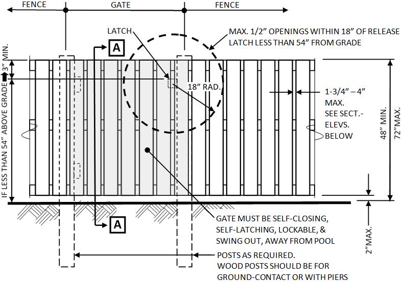
• The top of the barrier is at least 48” above grade for a distance of 3’-0” measured horizontally surrounding the outside of the barrier perimeter (SLCO Rev. Ord. SP305.2.1-Item 1, Exception).
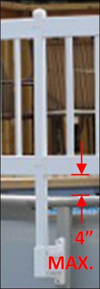
• Barrier vertical clearance is 2” maximum from grade, and 4” maximum from a solid surface, both measured on the side facing away from the pool (SLCO Rev. Ord. SP305.2.1-Item 2).
• Any openings provided in the barrier shall not allow passage of a 4” sphere (SP305.2.2).
• Barrier horizontal members less than 45” apart shall be placed on the pool side of the barrier. Space between the barrier’s solid vertical members shall be maximum 1-3/4” wide. Any decorative cutouts provided in barrier vertical members shall not be more than 1-3/4” wide (SP305.2.5).
• Barrier horizontal members more than 45” apart shall have a maximum 4” space width between solid vertical members. Any decorative cutouts provided in barrier vertical members shall be maximum 1-3/4” wide (SP305.2.6).
• A pedestrian access gate provided in a barrier must open outward away from the pool, must be self-closing, must have a self-latching device, and must be lockable or able to accommodate a locking device (SP305.3).
• Utility, vehicular, or service gates not for pedestrian access provided in a barrier - shall each be lockable (SP305.3.1).
• Each gate provided with double or multiple leafs must have at least 1 of leaf able to secure/hold in place, and the adjacent leaf must secure with a self-latching device. Openings within 18” of the latch-release mechanism shall be 1/2” maximum (SP 305.3.2).
• Provide the following where the release mechanism of a self-latching device is less than 54” above grade (SP305.3.3):
1. The gate release mechanism on the pool/spa side is at least 3” below the top of the gate;
2. Each gate and barrier opening within 18” of the release mechanism is not larger than 1/2”.
Made of Mesh, Other than Chain Link (SP305.2.4)
• Install in accordance with the manufacturer’s instructions.
• Submit electronic set of the manufacturer’s instructions with the permit application.
• Bottom of the fence shall be maximum 1” above grade, or decking.
• The mesh fence shall be fixed so the mesh lifts not more than 4” above grade or decking, and shall not allow the passage of a 4” sphere anywhere through the mesh fence.
• The mesh shall have attachment devices that are each hook-and-eye-type with a spring-actuated retaining lever located and shall be located at least 45” above grade.
• The mesh fence shall be approved non-climbable material, construction, and assembly. The mesh fence shall not be provided on top of on-ground/above-ground pools.
Made of Chain Link (SP305.2.7)
• As a barrier to pool access, openings cannot be more than 1-3/4” wide.
• Slats installed vertically or diagonally through the chain link openings must extend from top to bottom and be fastened at the top and bottom of the fence. Each reduced opening cannot be more than 1-3/4” wide.

Made of Diagonal Members – such as latticework (SP305.2.8)
• The diagonal cannot be more than 45 from vertical.
• The opening width cannot be more than 1-3/4”.
Made of Solid Masonry or Stone (SP305.2.3)
• Indentions and protrusions are prohibited that would be able to accommodate a foothold or handhold.
• Only normal construction tolerances and tooled masonry joints are allowed.
On-Ground//Above-Ground Pool Structure as Barrier
• The top of the pool shall be above grade, and the pool-as-barrier may extend to grade/ground level (SP305.5).
• A barrier may be mounted on top of an on-ground/above-ground pool structure that is compatible with the pool structure. The barrier shall have a maximum vertical clearance of 4” between the top of the pool structure and the bottom of the barrier (SLCO Rev. Ord. SP305.2.1-Item 4).
• The ladder(s) or stair(s) provided to enter an above-ground pool of adequate barrier height, or of adequate barrier height with the provision of a top-mounted barrier, shall be surrounded by a code compliant barrier to control access (SP305.5; SLCO Rev. Ord. SP 305.5).
Wall of Building as Barrier
• Provide the following where building wall(s) have openings with direct access to the pool (SP305.4):
1. Each building opening with direct pool access - like doors and windows with sill heights less than 48” above the building’s floor - have an audible alarm activated when any are opened, including the opening of their screens, AND
2. The alarm is listed and labeled as a water hazard entrance alarm in accordance with UL 2017, AND
3. The alarm deactivation switch(es) is/are located inside the dwelling at least 54” above the floor and in proximity to the passage door(s) with pool access. OR
4. A pool safety cover* compliant with ASTM F 1346.
*The safety cover does not eliminate the required exterior barrier enclosure of the pool, unless it is a powered safety cover for pools, and at least a lockable safety cover for spas and hot tubs (SP305.1). OR
5. Doors that are self-closing and have self-latching devices** with the release mechanism 54” vertically above the floor, may be considered for approval by the Authority Having Jurisdiction (Building Plan Review) on a case-bycase basis. It must be shown in the drawings and documents submitted such equipped doors provide at least the same level of protection as items 1-4 above.
Notice: Be aware an exterior door with an interior latch release mechanism 54” above the floor is not accepted as an emergency escape opening compliant with the requirements of the Code, and may not be allowed for some conditions.
**Compliance does not eliminate the sound-alarm requirement on windows.
Notice: Pool barriers other than those listed may be approved by Building Plan Review where the Reviewer can determine, from drawings and documents submitted, the barrier proposed is effectively compliant with code and ordinance requirements (SP305.1; SP305.2; SLCO Rev. Ord. SP305.2.1)
EXAMPLE ELEVATION OF REQUIREMENTS FOR POOL BARRIER & ITS POOL ACCESS GATE
EXAMPLE SECTION-ELEVATION DETAILS OF POOL BARRIER HEIGHT & SPACING REQUIREMENTS
