
Model Best Management Practices (BMP) for Land Disturbance
SEDIMENT AND EROSION CONTROL MANUAL
St. Louis County, Missouri
Department of Transportation
July 1, 2018

(This Page Intentionally Left Blank)
APPENDIX "A"
1/1/2016 i Table of Contents TABLE
Section Title Page No. Table of Contents, Appendix "A" and Standard Drawing Index i - iv General ....................................................................................................................................... v - vi Major Land Disturbance Permit Flowchart (Unincorporated County) ............................................... vii Major Land Disturbance Permit Flowchart (Contracting Municipality) ............................................. viii Land Disturbance..............................................................................................................................1 Definitions .........................................................................................................................................1 Service to Municipalities ...................................................................................................................5 Enforcement 6 Violations ..........................................................................................................................................8 Appeals ..........................................................................................................................................10 Land Disturbance Permits Required 11 Land Disturbance Permit Applications 16 Fees 18 Storm Water Pollution Prevention Plan (SWPPP) 19 Design Requirements - General 26 Inspections - General 37 Land Disturbance Inspection Oversight 40 Notes 41 Public Notification Signs 42 Public Notification Signs (Sign Examples) 43 Procedure for Receiving Written and Verbal Information from the Public Concerning Construction Sites 1 Acre and Above, Located in Unincorporated St. Louis County, Missouri and Contracting Municipalities 44 Sketch Plan Requirements for Major Land Disturbance Permit 46 Submission Requirements of the Department of Planning 47
OF CONTENTS
Section Title Page No. County Inspections .........................................................................................................................48 Post-Construction Storm Water Management in New Development and Redevelopment ............... 49 Stream Buffer Standards (In-Part) ..................................................................................................50 "KP" Karst Preservation District Regulations (In-Part) ..................................................................... 52
1/1/2016 ii Table of Contents Section Title Page No. Amended Soil Post Construction BMP's in County Right of Way 53 Dust Control 54 Erosion Control 56 Permanent Erosion Control Geotextile Requirements 57 Table 1 - Geotextile Class (Chart) 58 Turf Reinforcement Mat (TRM) 59 Table 1 - Standard Specifications for Turf Reinforcement Mat (TRM) Products (Chart) 62 Hydraulic Erosion Control Product (HECP) 63 Table 1 - Performance Chart for Standard HECP's (Chart) ...................................................... 63 Mulch 66 Mulch Selection as a Function of Slope (Chart) ........................................................................ 67 General Mulch Recommendations to Protect from Splash and Sheet Flow (Chart) .................. 67 Rock Outlet / Embankment Protection / Paved Ditch 68 Seeding ..........................................................................................................................................70 Seeding Requirements (Chart) .................................................................................................71 Sodding ..........................................................................................................................................73 Soil Binders ....................................................................................................................................74 Stream Bank Protection ..................................................................................................................75 Temporary Stream Crossing ...........................................................................................................76 Non-Sediment Pollution Control ......................................................................................................77 Pollution Prevention Procedures .....................................................................................................78 Check Dam 81 Diversion - Ridge & Channel 82 Diversion - Storm Sewer 83 Gradient Terraces 84 Grass Lined Channel 85 Gravel Bags 86 Level Spreader 87 Surface Roughening 88 Temporary Slope Drain 89 Filter Strip 90 Inlet Protection - Block & Gravel, Gravel Bags, and Fiber Rolls 91 Inlet Protection - Fabric Drop and Drop In Filter 92
STANDARD DRAWINGS
1/1/2016 iii Table of Contents Section Title Page No. Inlet Protection - Sod Filter 93 Sediment Basin 94 Sediment Trap 96 Silt Fence 97 Table 1 - Temporary Silt Fence Property Requirements (Chart) 99 Fiber Rolls and Filter Rolls 100 Dewatering 102 Construction Entrance 104 Construction Road 105 Washdown Station 106 Vehicle Maintenance and Washing Areas 107 Concrete Waste Management 108 References ...................................................................................................................................111
Drawing Title Drawing No. Page No. Standard Drawings Cover Sheet ................................................................................................... 113 Sodding 803-10.00 114 Temporary Slope Drain 806-20.12 115 Check Dam 806-35.00 116 Sediment Basin 806-40.01 117 Sediment Trap 806-40.02a 118 Sediment Trap 806-40.02b 119 Sediment Trap - Single Chamber 806-40.03 120 Sediment Trap - Double Chamber 806-40.04 121 Inlet Protection - Block and Gravel 806-45.02 122 Inlet Protection - Sod Filter 806-45.06 123 Grated Unit, Inlet and Gutter Protection Filter Sock and Gravel Filter Bag 806-45.08 124 Inlet Protection - Fabric Drop ......................................................................... 806-45.12 .............. 125 Construction Road ......................................................................................... 806-45.99 .............. 126 Washdown Station ......................................................................................... 806-46.00 .............. 127
1/1/2016 iv Table of Contents Drawing Title Drawing No. Page No. Construction Entrance 806-46.01 128 Concrete Waste Management (Concrete Washout Sign) 806-46.03 129 Rock Outlet 806-55.10 130 Temporary Stream Crossing 806-55.12 131 Temporary Diversions - Ridge and Channel 806-55.14 132 Gradient Terraces 806-55.15 133 Grassed Lined Channel 806-55.16 134 Gravel Bags 806-55.17 135 Level Spreader 806-55.18a 136 Level Spreader 806-55.18b 137 Surface Roughening 806-55.19 138 Filter Strip 806-55.20 139 Fiber Rolls and Wattles (Type 1 Staking) ....................................................... 806-65.00 .............. 140 Fiber Rolls and Wattles (Type 2 & Type 3 Staking) ........................................ 806-65.01 .............. 141 Filter Rolls (Filter Socks) (Type 4 Staking) ..................................................... 806-65.02 .............. 142 Silt Fence....................................................................................................... 806-70.00 .............. 143
GENERAL
MODIFICATIONS - Special situations may warrant variation from these published policies and provisions Wherever there are practical difficulties involved in carrying out the provisions of this standard, the St. Louis County Department of Transportation Official shall have the authority to grant modifications for individual cases, upon application (in writing to include a standard detail drawing) of the owner or owner's representative, provided the Department of Transportation Official shall first find that special individual reason makes the strict letter of this standard impractical and the modification is in compliance with the intent and purpose of the code/manual and that such modification does not lessen highway safety, health, accessibility, or structural requirements. The details of action granting modifications shall be recorded and entered in the files of the St. Louis County Department of Transportation Provisions in this manual are the minimum required If provisions in this manual conflict with similar provisions from a different regulating authority, the more restrictive provision governs The provisions of this manual shall not be deemed to nullify any provisions of County, state or federal law This manual is not a textbook or a substitute for engineering or technical knowledge, experience or judgment.
ALTERNATIVE MATERIALS, DESIGN AND METHOD OF CONSTRUCTION AND EQUIPMENT
The provisions of this standard are not intended to prevent the installation of any material or to prohibit any design or method of construction not specifically prescribed by this standard, provided that any such alternative has been approved An alternative material, design or method of construction shall be approved where the St. Louis County Department of Transportation Official finds that the proposed design is satisfactory and complies with the intent of the provisions of this standard, and that the material, method of work offered is, for the purpose intended, at least equivalent of that prescribed in this standard in quality, strength, effectiveness, durability and safety.
The mention of any specific commercial product, process or service in this manual is not to be construed as an actual or implied endorsement, recommendation or warranty thereof by St. Louis County. St. Louis County makes no representation or warranty of any kind, whether expressed or implied, concerning products or processes discussed in this manual and assumes no liability there from.
The guidance and provisions published herein are subject to amendment by St. Louis County as conditions, agency requirements and experience warrant.
REGULATORY REQUIREMENTS - Legislative actions by the United States Congress, states, counties, and cities have been put in place to protect the environment. Construction projects are required to follow procedures that protect the environment Some examples of federal regulatory requirements that apply to local construction sites include the following:
1) National Environmental Policy Act (NEPA)
2) Clean Water Act (CWA)
3) Endangered Species Act (ESA)
4) Resource Conservation and Recovery Act (RCRA)
5) Federal Insecticide, Fungicide and Rodenticide Act (FIFRA)
One piece of legislation that considerably impacts construction sites is the Clean Water Act (CWA). The CWA provides a comprehensive, nationwide approach to water quality protection. It requires federal, state and local governments to act cooperatively f or the accomplishment of common goals. The Environmental Protection Agency (EPA) classifies storm water runoff from construction sites as a
1/1/2016 v General
point discharge from an industrial activity Such storm water discharges from construction related activity having a land disturbance of 1 acre or more, or less than 1 acre that is part of a larger common plan proposed development that will ultimately disturb 1 acre or more, needs to be authorized by a National Pollutant Discharge Elimination System (NPDES) General Permit also known as the Construction General Permit (CGP) issued by the Missouri Department of Natural Resources (MDNR) Other permits may also apply. From time to time the EPA will update their construction site storm water regulations, which construction site operators are required track and implement NOTE: As of October 1, 2011, EPA has authorized 46 states and the Virgin Islands to implement the basic NPDES program as well as the general permits program; Missouri is an "EPA State", which means the EPA assigns its authority to the MDNR to enforce and carry out its Clean Water objectives The County, EPA or MDNR can enter a construction/land disturbance site at any time, announced or not, to perform a regulatory compliance inspection.
MISSOURI ONE CALL SYSTEM - It is suggested that anyone planning on disturbing land or installing BMP's, etc., first read the Missouri Law concerning underground facility safety and damage prevention to gain a better understanding of underground damage prevention. (Example: Driving a silt fence stake into the ground can potentially damage an underground facility.) The Missouri One Call website address is: www.mo1call.com/index.php. A copy of the Missouri Law can be found online at: www.mo1call.com/law/law.php.
It is the responsibility of the Contractor, permitee, property owner and sub-contractors performing work to contact the Missouri One Call System at (800) 344-7483, 811, or Internet Ticketing (ITIC) at www.mo1call.com/itic/index_gen.php (and also St. Louis County Operations Division about signal and/or lighting conduit at (314) 615-0215) at least three (3) full working days before commencing the excavation/grading activity. If working in a City or Municipality, contact that City or Municipality in addition to the Missouri One Call System at least three (3) full working days before commencing the excavation/grading activity.
ST. LOUIS COUNTY PERMIT IDENTIFICATION - St. Louis County is covered under an umbrella National Pollutant Discharge Elimination System (NPDES) Land Disturbance permit (No. MOR100008), issued to the County by the Missouri Department of Natural Resources (MDNR). It can be applied to all County Department's construction projects that disturb one acre or more of land. Please be aware that a copy of the MDNR Land Disturbance Permit must be included in the contract specifications for the project. Additionally, a storm water pollution prevention plan (SWPPP) must be prepared for the project and the land disturbance permit requirements must be followed on the project. Contact the Department's Storm Water Manager at (314) 615-8157, at the start of the project to register your project. This registration is mandatory and is needed to comply with MDNR reporting requirements. All County Departments have the option to apply for a separate, individual, land disturbance permit from the local MDNR office at their discretion in lieu of using the MDNR land disturbance permit. This must also be registered with the Department's Storm Water Manager. A copy of the MDNR land disturbance permit can be found on the County's Intranet site (employees only) at: countynet.stlouisco.net/News/Pages/OperationsandMaintenanceManual.aspx A hard copy of the MDNR land disturbance permit is available to the public for a small fee to cover the cost of copying. A separate land disturbance permit, issued by the County, in addition to the MDNR Land Disturbance Permit may also be required on construction projects
1/1/2016 vi General
LAND DISTURBANCE
The purpose of the "Land Disturbance Code", (Ordinance Number 25,494, approved on July 31, 2013, by the County Executive) is to safeguard persons, protect property, and prevent damage to the environment in St Louis County.
On Construction or Land Disturbance Sites, soil is highly vulnerable to erosion by wind and water Eroded soil endangers water resources by reducing water quality and causing the siltation of aquatic habitat for fish and other desirable species Deposits of eroded soil also necessitate maintenance of sewers and ditches and the dredging of lakes In addition, clearing and grading during construction cause the loss of native vegetation necessary for terrestrial and aquatic habitat Construction activities also utilize materials and generate wastes, which if not properly controlled can pollute receiving waters.
The O&M Procedures contained herein are a function of the Department of Public Works Any questions regarding these procedures shall be handled through the Department of Public Works.
For the purpose of this code, the following terms, phrases, words, and their derivations shall have the meaning given herein Where terms are not defined by this section, such terms shall have ordinarily accepted meanings such as the context implies.
DEFINITIONS
Best Management Practices Practices, procedures, methods, devices, or a schedule of (BMP or BMPs) activities to reduce the amount of sediment and other pollutants in storm water discharges associated with construction and Land Disturbance Activities.
Board
Borrow Pit or Site
Clearing
Code or the Code
Commercial
Community Garden
The Board of Appeals or Building Commission as provided for in Section 4.330, St. Louis County Charter.
An area where material (usually soil, gravel, or sand) is excavated for use at another location.
Any activity that removes the vegetative surface cover or destroys the root system.
The "Land Disturbance Code" of St. Louis County, Missouri, as adopted by St. Louis County Ordinance.
A development for or consisting of any type of use other than Residential as defined in the code.
A single piece of land gardened collectively by a group of people for the purpose of growing fresh vegetables and similar produce for their own consumption or to donate to others.
7/1/2018 Page 1 Sediment and Erosion Control Manual
Construction or Land
A parcel or contiguous parcels, where Land Disturbance Disturbance Site Activities are performed as part of a proposed development.
County St. Louis County, Missouri.
Department of Health
Department of Planning
Department of Public Works
Department of Transportation
Disaster
Drainage Way
Emergency
Erosion
Erosion Control
Grading
Heavy Rainfall
Land Disturbance Activities
The St. Louis County Department of Health, acting through its Director, or their duly authorized designee.
The St. Louis County Department of Planning, acting through its Director, or their duly authorized designee.
The St. Louis County Department of Public Works, acting through its Director, or their duly authorized designee.
The St. Louis County Department of Transportation, acting through its Director, or their duly authorized designee.
A disaster shall include but not necessarily be limited to a flood, windstorm, tornado, severe storm, earthquake, bomb blast, explosion, or similar natural or man-made type event. The code official shall make the determination whether an event shall be declared a disaster.
Any channel that conveys surface runoff through a site.
An event or occasion that requires immediate action in order to preserve or restore the public peace, health, safety or welfare.
The wearing away of land surface through the action of wind or water.
Any Best Management Practices (BMPs) that prevents or minimizes erosion.
Reshaping the ground surface through excavation and / or fill of material, including the resulting conditions.
A rainfall intensity that causes erosion.
Clearing and grubbing, grading or any related work which results in removal of the natural site vegetation or destruction of the root zone or otherwise results in leaving the ground surface exposed to soil erosion through the action of wind or water.
7/1/2018 Page 2 Sediment and Erosion Control Manual
Land Disturbance, Major
Any Land Disturbance Activity involving one (1) acre or more of land or a site involving less than one (1) acre that is part of a common plan proposed development that will ultimately disturb one (1) acre or more.
Land Disturbance, Ordinary
Land Disturbance Permit
Any Land Disturbance Activity involving less than one (1) acre of land
A permit issued by the authority having jurisdiction authorizing a Land Disturbance Activity at a specific site subject to conditions stated in the permit A permit may be for any one or more Major or Ordinary Land Disturbance Activities.
Perimeter Control
A barrier that prevents sediment from leaving a site by filtering sediment-laden runoff or diverting it to a sediment trap or basin.
Phasing
Qualified Professional
Clearing a parcel of land in distinct phases, with the stabilization of each phase substantially completed before the clearing of the next.
A Missouri licensed professional engineer or person who has been tested and certified by an independent organization as having passed an examination in the principles and practices of erosion and sediment control and methods to prepare SWPPPs and who is also knowledgeable in the principles and practices of erosion and sediment control, including best management practices described in the Code.
Residential
Runoff Coefficient
Sediment Control
Site Construction Plan
A development for or consisting of detached single-family dwellings, detached two family dwellings, or multiple single-family dwellings (townhouses).
The fraction of total rainfall that exits at the outfalls from a site.
Any Best Management Practices (BMPs) that prevents eroded sediment from leaving a site.
Written, graphic and pictorial documents prepared or assembled for describing the design, location and physical characteristics of land disturbance activities and related features, elements and components of a project necessary for obtaining a land disturbance permit.
7/1/2018 Page 3 Sediment and Erosion Control Manual
Special Inspections
Inspection requiring special expertise of the erosion and sediment and other pollutant control measures, outfalls and off-site receiving waters, the purpose of which is to insure the proper installation, operation and maintenance of the Best Management Practices (BMPs) and to determine the overall effectiveness of the Storm Water Pollution Prevention Plan (SWPPP) and the need for additional control or corrective measures.
Stabilization
Standard Specifications for Road and Bridge Construction
The use of Best Management Practices (BMPs) that prevent exposed soil from eroding from a land disturbance site.
The basis for all roadway construction and incidental work to be performed on roadways under the jurisdiction of St. Louis County. The specifications can be found at: www.stlouisco.com/YourGovernment/CountyDepartme nts/HighwaysandTraffic/TransportationPublicationsMa nuals/StandardSpecificationsforHighwayConstruction.
Start of Construction
Stockpile
Storm Water Pollution Prevention Plan(s) (SWPPP or SWPPPs)
The first Land Disturbance Activity associated with a development.
A temporary pile or storage location on a commercial site for materials that can be used as approved fill material under this code as future on-site fill or as fill at another approved location for proposed development that is in the permit/review approval process.
A management plan, the purpose of which is to ensure the design, implementation, management and maintenance of Best Management Practices (BMPs) in order to reduce the amount of sediment and other pollutants in storm water discharges associated with Land Disturbance Activities, comply with the standards of St. Louis County, and ensure compliance with the terms and conditions of the applicable state permits, including adherence to the land disturbance program contained in Missouri state issued Municipal Separate Storm Sewer System MS4 NPDES permits.
Water Course
A natural or artificial channel or body of water, including but not limited to, lakes, ponds, rivers, streams, ditches and other open conveyances that carry surface runoff water either continuously or intermittently.
7/1/2018 Page 4 Sediment and Erosion Control Manual
SERVICE TO MUNICIPALITIES
101.6.1 Contracting with Municipalities. The County Executive is hereby authorized to contract with municipalities within the County to provide appropriate services to enforce the requirements of the Code, and further to collect fees for applicable permits and inspections issued or made pursuant to such contracts No contract for services under the Code shall be entered into until the municipality desiring to contract with the County for enforcement of the Code shall:
1) Contract with the County for explosives code enforcement services; and
2) Adopt a code identical in substance to the Code; and
3) Perform the functions associated with the authority and responsibilities of the St. Louis County Department of Planning identified in Section 103.1 of the Code (shown below), or other mutually agreeable services; and
4) Perform the functions associated with the authority and responsibilities of the St. Louis County Department of Transportation identified in Section 103.3 of the Code (shown below) with respect to municipal streets and roadways and flood plain administration and enforcement or other mutually agreeable services.
101.6.2 Municipal Zoning Approval. All plans for Land Disturbance Activities within the corporate limits of any municipality that contracts with the County for code enforcement services shall be reviewed and approved by the contracting municipality for compliance with its zoning or other municipal regulatory ordinances or provisions prior to issuance of a County permit under the Code.
102.1 Other Laws. The provisions of the Code or this manual shall not be deemed to nullify any provisions of County, State or Federal Law.
102.2 Referenced Standards and Manuals. The standards and manuals referenced below shall be considered a part of the requirements of the Code. Where conflicts occur between the provisions of County ordinances, including the Code, and the referenced standards and manuals, the provisions of County ordinances shall apply.
1) County's "Model Best Management Practices (BMP) for Land Disturbance - Sediment and Erosion Control Manual".
2) County's "Design Criteria for the Preparation of Improvement Plans" manual.
3) County's "Standard Specifications for Road and Bridge Construction" manual.
4) Standard Method 2540 F from the "Standard Methods for Examination of Water and Wastewater" jointly published by the American Public Health Association (APHA), the American Water Works Association (AWWA), and the Water Environment Federation (WEF)
7/1/2018 Page 5 Sediment and Erosion Control Manual
ENFORCEMENT
103.1 Department of Planning. The Department of Planning shall have the authority and responsibility to perform the following functions related to the enforcement of the Code as associated with Major Land Disturbance Permits:
1) Administer the determination, collection and release of land disturbance escrows required by this Code in coordination with the Department of Transportation and the Department of Public Works
103.2 Department of Public Works. The Department of Public Works shall have the authority and responsibility to perform the following functions related to the enforcement of this Code:
1) Receive applications for Major Land Disturbance Permits.
2) Coordinate the review of Major Land Disturbance permit applications and accompanying documents with the Department of Transportation and Department of Planning
3) Coordinate the issuance of the Major Land Disturbance permit with the Department of Transportation and Department of Planning, and issue such permits Such permits may authorize any one or more Major Land Disturbance Activity.
4) Inspect Commercial Land Disturbance Activities; and residential land disturbance activity associated with permitted construction of buildings or structures.
5) Inspect Commercial Land Disturbance Activities within or abutting areas designated onehundred (100) year flood plain.
6) Receive applications, perform plan review, inspect and issue permits for Ordinary Land Disturbance Activities relating to Best Management Practices (BMPs) to be utilized to control erosion and sedimentation from leaving the site during construction and other Land Disturbance Activities.
103.3 Department of Transportation. The St. Louis County Department of Transportation shall have the authority and responsibility to perform the following functions related to the enforcement of the Code:
1) Plan review of Major Land Disturbance Activities.
2) Plan review and inspection of Land Disturbance Activities related to construction, repair, maintenance, or condition of roadways and roadway rights-of-way which are maintained by the County.
3) Plan review of Land Disturbance Activities within or abutting areas designated one- hundred (100) year flood plain.
4) Inspect residential Land Disturbance Activities within or abutting areas designated one-hundred (100) year flood plain.
7/1/2018 Page 6 Sediment and Erosion Control Manual
5) Inspect residential Land Disturbance activities except activities associated with permitted construction of buildings and structures.
103.4 Protection of Adjacent Property. No Major Land Disturbance Permit or Ordinary Land Disturbance Permit shall be issued where the Department of Transportation and / or the Department of Public Works, finds that the proposed land disturbance activity would result in a material change in the amount or pattern of surface water run-off to the substantial injury of neighboring public or private property or right-of-way.
All land disturbance activities shall be carried out in such a manner as to minimize inconvenience and harm to adjacent properties and property owners.
103.5 Rule-Making Authority. County Departments having enforcement authority and responsibilities described in the Code shall have the authority, as necessary in the interest of public health, safety and general welfare, to adopt and promulgate rules and regulations to interpret and implement the provisions of the Code, in order to secure the intent thereof, and to designate requirements applicable because of local climatic or other conditions. Such rules and regulations shall not have the effect of waiving requirements specifically provided for in the Code or of violating accepted engineering practices involving the purpose of the Code.
7/1/2018 Page 7 Sediment and Erosion Control Manual
VIOLATIONS
104.1 Unlawful Acts. It shall be unlawful for any person, firm or corporation to perform any Land Disturbance Activities, or cause or allow same to be done without obtaining the appropriate permit to do so or to be otherwise in conflict with or in violation of any of the provisions of the Code.
104.2 Notices of Violation. When the Department of Transportation, or the Department of Public Works determines that a violation of the Code exists, the respective Director shall notify the violator The notification shall be in writing and shall be delivered to the violator or their legally authorized representative or mailed to his last known address via first class mail postage prepaid Any person having been notified that a violation exists and who fails to abate the violation within seven calendar days after notification shall be subject to the penalties enumerated in the Code
104.2.1 Notices of Violations on Department of Transportation Projects. The Notice of Violation will consist of the site SWPPP Construction Site inspection report delivered to the contractor by the Resident Engineer or their assign Any person having been notified that a violation exists and who fails to abate the violation within seven calendar days after notification shall be subject to the penalties enumerated in the Code and/or penalties issued by the Missouri Department of Natural Resources (MDNR) and/or the Environmental Protection Agency (EPA).
104.3 Prosecution of Violation. If the violator does not abate the violation promptly, the Department of Transportation, or the Department of Public Works shall request the County Counselor to institute the appropriate proceeding at law or in equity to restrain, correct or abate such violation.
104.4 Violation, Penalties. Any person, firm or corporation who shall violate any provision of the Code, or who shall fail to comply with any of the requirements thereof, or who shall perform work in violation of the approved construction documents or the Storm Water Pollution Prevention Plan (SWPPP), or any directive of the Department of Transportation, or the Department of Public Works, or of a permit or certificate issued under the provisions of the Code, or shall start any work requiring a permit without first obtaining a permit therefore, or fail to call for the required County inspections, or fail to cause or make the Special Inspector's regular and after-rain inspections or file the required special inspector weekly report, or who shall continue any work on or about the site after having been served a stop-work order, except for such work which that person, firm or corporation has been directed to perform to remove a violation or unsafe conditions, or assists in any violation of the Code or who maintains any property on which such violation shall exist, shall be guilty of a misdemeanor, punishable by a fine of not more than $1,000 or by imprisonment not exceeding 90 days, or both such fine and imprisonment. Each day that a violation continues shall be deemed a separate offense.
104.4.1 Failure to Obtain a Permit. In addition to the actions and penalties contained in sections 104.3 and 104.4 above, the County may implement the following procedure when work has been started prior to issuance of a permit required by the Code:
1) Issue a stop work order.
2) Assess an Administrative Penalty which shall not exceed the greater of $500 or 1 percent of the cost of the land disturbance activities In making the assessment, the Department will consider whether the violator has previously violated the Code and whether the occupation or experience of the violator indicates that he / she knew or should have known that a permit was required
7/1/2018 Page 8 Sediment and Erosion Control Manual
104.4.2 Failure to perform Special Inspections, Produce Special Inspector Reports, Request Inspections, or Implement BMPs. In addition to the actions and penalties contained in Sections 104.3 and 104.4 above, County may implement the following procedure, when a person fails to conduct special inspections, fails to submit special inspector reports, fails to schedule the required inspections, or fails to implement BMPs, including re-establishing permanent vegetation on the site as required by this Code:
1) Issue a violation, and, if the violation is failure to perform special inspections or produce special inspection reports, also issue a stop work order.
2) Assess an administrative penalty which shall not exceed $500; except that in addition, assess an administrative penalty of up to $100 per day for failure to implement BMPs. In making the assessment, the Department will consider whether the violator has previously violated this Code and whether the occupation or experience of the violator indicates that he/she knew or should have known that Special Inspector Inspections, Special Inspector Reports, or County Inspections were required, or that BMPs were required to be implemented.
104.5 Appeal. Appeals from County actions or penalties imposed pursuant to Section 104.4.1 or 104.4.2 shall be governed by provisions relating to appeals to the Board contained in Section 105.
104.6 Abatement of Violation. The imposition of the penalties herein prescribed shall not preclude the County Counselor from instituting appropriate action to prevent unlawful construction or to restrain, correct or abate a violation, or to prevent illegal use of a property or to stop an illegal act.
104.7 Permit Suspension or Revocation. County may suspend or revoke any permit if the permit is issued in error or on the basis of incorrect, inaccurate, or incomplete information, or in violation of any County Ordinance, including the Code, or any state or federal regulation. In addition, County may suspend or revoke any permit when a Land Disturbance Activity is conducted in violation of the requirements of the Code or the terms of the permit in such a manner as to materially adversely aff ect the safety, health or welfare of persons, or materially be detrimental or injurious to property or improvements.
104.8 Stop Work Order. In addition to the stop work orders issued pursuant to section 104.4.1 and 104.4.2, upon notice from the Department of Transportation, or the Department of Public Works that work on any property is being prosecuted contrary to the provisions of the Code or in an unsafe and dangerous manner, the person performing such work shall stop work immediately. The stop work order shall be in writing and shall be given to the owner of the property involved, or to the owner's agent, or to the person doing the work; and shall state the conditions under which work will be permitted to resume.
7/1/2018 Page 9 Sediment and Erosion Control Manual
APPEALS
105.1 Application for Appeal. Any person shall have the right to appeal a decision of the Department of Transportation, the Department of Public Works, or the Department of Planning to the Board The Board shall consist of the members of the Building Commission created in Article IV, Section 4.330 of the St. Louis County Charter.
105.1.1 Filing Procedure. All appeals shall be filed in writing with the Department of Public Works All appeals shall be filed within thirty (30) days after the decision to be appealed is rendered by the Departments identified in this section.
105.1.2 Filing Fee. All appeals must be accompanied by a fee in the amount specified in Chapter 1100, SLCRO 1974, as amended The current appeal filing fee is $56 (subject to revision).
105.2 Notice of Hearing on Appeal. The Board shall meet upon notice from the Chairman, within thirty (30) days of the filing of an appeal, or at stated periodic meetings.
105.3 Open Hearing. All hearings before the Board shall be open to the public The appellant, the appellant's representative, the County Department(s) having enforcement authority and responsibilities described in section 103 of the Code, and any person whose interests are affected, shall be given an opportunity to be heard.
105.4 Procedure. The Board shall adopt and make available to the public procedures under which a hearing will be conducted The procedures shall not require compliance with strict rules of evidence but shall mandate that only relevant information be received.
105.5 Board Decision. Decisions by the Board to reverse or modify a decision by a Department requires a minimum vote of three members.
105.6 Resolution. The decision of the Board shall be in writing and shall consist of findings of fact and conclusions of law. Copies shall be furnished to the appellant and to the County Department(s) having enforcement authority and responsibilities.
105.7 Court Review. A party adversely affected by a decision of the Board may appeal to an appropriate court from such decision. Application for review shall be made in the manner and time required by law following the filing of the findings of fact and conclusions of law.
7/1/2018 Page 10 Sediment and Erosion Control Manual
LAND DISTURBANCE PERMITS REQUIRED
A land disturbance permit is required for any "Land Disturbance Activity" such as clearing, rough grading (cutting and / or filling), excavating, finish grading, or any related work, which reshapes the ground surface or otherwise results in the removal and/or destruction of natural vegetation and / or results in the ground surface being exposed and / or destruction of the root zone, or otherwise results in leaving the ground surface exposed to soil erosion through the action of wind or water. A land disturbance permit is required for any disturbance in the unincorporated areas of St. Louis County and in Municipalities that contract with St. Louis County for land disturbance and building plan review and inspection service. For a list of Municipalities that contract with the County, see the Municipal Matrix located at:
www.stlouisco.com/YourGovernment/CountyDepartments/PublicWorks/ Documents/MunicipalMatrix
106.1 County Permit Required. Any person who intends to conduct any Land Disturbance Activity must obtain a permit prior to beginning the activity The type of permit shall be as req uired by Sections 106.1.1 or 106.1.2 (shown below) in the Code.
Exception: Activities that do not require permits under Section 106.3 of the Code.
106.1.1 Major Land Disturbance Permit. No person shall perform any Major Land Disturbance Activity prior to receipt of a Major Land Disturbance Permit. Applications for Major Land Disturbance Permits shall be filed with the Department of Public Works.
Exception: Activities that do not require permits under Section 106.3 of the Code.
106.1.2 Ordinary Land Disturbance Permit. No person shall perform any Ordinary Land Disturbance Activity prior to receipt of an Ordinary Land Disturbance Permit. Applications for Ordinary Land Disturbance Permits shall be filed with the Department of Public Works.
Exceptions:
1) Activities that do not require permits under Section 106.3 of the Code.
2) An Ordinary Land Disturbance Permit is not required for St. Louis County Department of Transportation, and Department of Parks and Recreation projects; provided sediment and erosion control measures are provided until grass or other vegetation is established or other approved ground cover means are used.
7/1/2018 Page 11 Sediment and Erosion Control Manual
The area of land disturbance includes the area where the excavation is removed and stockpiled, the area where spoil is graded or wasted, the path created by machinery to get to the land disturbance locations, or any other additional area of disturbance needed to perform the work at a site They all fall under the above definition for "Land Disturbance Activities" If they collectively total the following amounts, the following requirements apply:
Collective Total Amount Requirement
One (1) acre or more of land or a site involving Need SWPPP approval and a less than one (1) acre that is part of a Major Land Disturbance Permit common plan proposed development that will ultimately disturb one (1) acre or more.
Greater than 2,000 sq. ft. and ................................... Need an Ordinary Land Disturbance Permit less than 1 acre
Less than 2,000 sq. ft., and includes ......................... Need an Ordinary Land Disturbance Permit other grading in an amount greater than 30 cubic yards.
Less than 2,000 sq. ft. and includes ................................... No Land Disturbance Permit required other grading in an amount less provided all of the requirements of than 30 cubic yards. Section 106.3 on Page 13 are met
Note: A Special Use Permit (SUP) will be required from the St. Louis County Department of Transportation for the construction of a temporary entrance at a site.
Also see Section 106.3 on Page 13 titled "Exceptions - Land Disturbance Permits Not Required".
106.1.2.1 County Building Construction Permits and Related Ordinary Land Disturbance Activities. The Department of Public Works may include Ordinary Land Disturbance Activities associated with the construction of a building, structure, or parking lot and installation of associated utilities, sewers or equipment serving the building, structure, or parking lot authorized by a permit issued under the building , plumbing, electrical and mechanical codes, as an integrated permit for the proposed construction.
106.1.2.2 Land Disturbance Activities Related to Emergency Work. Where work and associated land disturbance activities must be performed in an emergency situation to protect the health, safety and welfare of the general public, other than disaster response activities described in Item 1 of Section 106.3, the application for permit must be filed within 48 hours (two business days). Every person shall immediately report all emergency work to the Department of Public Works, or in the case of work within a roadway to the Department of Transportation and apply for appropriate permits pursuant to procedures directed by the Department.
7/1/2018 Page 12 Sediment and Erosion Control Manual
106.2 Limitation on Transfer of Land Disturbance Permit. Any person who buys land from a person who has been issued a land disturbance permit under Sections 106.1.1 or 106.1.2 (shown above) of the Code must obtain a separate land disturbance permit from County.
Exceptions: Portions of a site having a Major Land Disturbance permit may be transferred to a new landowner provided the original permit holder obtains the approval of the Department of Planning, and the Department of Public Works to retain responsibility for the Land Disturbance Activities on the remaining portions of such property not transferred to the landowner
106.3 Exceptions - Land Disturbance Permits Not Required. Land Disturbance Permits are not required for the activities identified as items 1 and 7 in this section, nor are such Permits required for the activities identified in Items 2, 3, 4, 5 and 6, provided the activity does not alter, or cause to be altered, the present surface of the ground:
• By any cut or fill at the property line.
• By any cut or fill that would permanently divert one drainage area to another drainage area.
• By any cut or fill which would deposit mud or harmful silt, or create erosion or damage to adjoining properties.
• By any cut or fill that would block or affect an existing swale or drainage path in a manner to cause damming and ponding.
• By cut or fill within a flood plain without a flood plain study being approved by the County.
• By any cut or fill within a creek or waterway channel.
1) Any disaster response activity that is immediately necessary for the protection of life, property, or natural resources
2) Existing farming, nursery and agricultural operations conducted as an allowed main or accessory use.
3) Land Disturbance Activities involving less than thirty (30) cubic yards of earth / soil moved and less than 2,000 square feet of disturbed area provided the Land Disturbance Activity is for the improvement of the property. Erosion and sediment control measures shall be provided when necessary, until grass or other vegetation is established or other approved means of ground cover are used.
4) Land Disturbance Activities associated with additions to and accessory structures for one and two family dwellings.
5) Removal of existing or dying grass or similar vegetation by disturbing not more than over a maximum area of 10,000 square feet and re-sodding or re-seeding with new landscaping to include preparation of the seed bed; provided erosion and sediment control measures are provided until the grass or other vegetation is established Any cut or fill in conjunction with the preparation of the seedbed shall not exceed thirty (30) cubic yards.
7/1/2018 Page 13 Sediment and Erosion Control Manual
6) Gardening and similar activities on existing property occupied by one or two family dwellings and Community Gardens less than 2,000 square feet in area, provided there is a vegetative buffer around the perimeter of the garden or other approved method to prevent eroded sediment from leaving the site
7) Land Disturbance Activities by any public utility for the installation, inspection, repair or replacement of any of its equipment or for its collection or distribution lines or piping systems; provided sediment and erosion control measures are provided until grass or other vegetation is established or other approved ground cover means are used This exception does not apply to any Land Disturbance Activity associated with work that requires a building permit or special use permit.
106.4 State of Missouri and Other Agency Permits Required. The permit applicant shall obtain a land disturbance permit from the State of Missouri Department of Natural Resources (DNR) for any site where one (1) acre or more of land will be disturbed before beginning any site work authorized by a County permit. This requirement applies to sites of less than one acre that are part of a proposed development that will ultimately disturb one (1) acre or more.
If permits are also required from other County Departments or from State or Federal agencies, the permit applicant shall obtain the required permits before beginning any site work authorized by a County land disturbance permit.
106.5 Specialized Land Disturbance Permit. A specialized land disturbance permit may be issued for clearing and grubbing, borrow pits or sites, stockpiling of approved fill materials, rough grading, or similar specialized work provided applicant has submitted a SWPPP, adequate plans, and information complying with pertinent requirements of this Code for the advance work. The holder of such specialized permit shall proceed at their own risk with the scope of land disturbance work authorized without assurance that additional land disturbance activities will be approved. If County does not approve additional land disturbance activities, the holder of the specialized permit shall maintain temporary sediment and erosion control measures until permanent engineered BMPs are installed, if required, and permanent vegetation on the site is re-established.
106.6 Posting of Permit and Inspection Placard. Work requiring a permit shall not commence until the permit-holder posts the permit and inspection placard at the job site for the recording of inspections. The permit and inspection placard shall be placed in a transparent envelope or other approved transparent receptacle that provides weather protection and kept on the site of work in an approved location until the completion of the land disturbance work.
106.7 Expiration Land disturbance permits shall expire and become invalid under any of the following conditions:
1) Work on the site does not commence within 180 calendar days after issuance of the permit;
2) Work on the site is suspended or abandoned for a period of 180 calendar days;
3) More than six (6) months has transpired since the issuance of an Ordinary Land Disturbance Permit, and no extension has been requested;
7/1/2018 Page 14 Sediment and Erosion Control Manual
4) More than two (2) years have transpired since the issuance of the Major Land Disturbance Permit, and no extension has been requested;
5) The deposit agreement required by the Planning Department for the Major Land Disturbance is no longer valid.
6) If requests for extension have not been granted.
The Department of Public Works may issue permits having a longer duration than indicated above for land disturbance activities associated with quarries, sand and gravel dredging operations, and similar long-term specialized borrow pit or site excavation operations The Department shall collect the permit extension fees that normally would otherwise be collected in accordance with Section 106.7.1, along with fees for any additional inspections that may be required, at the time the permit having a longer duration is issued. Permits issued for longer durations shall have an expiration date. Upon expiration of the longer duration permit the Department of Public Works may grant additional extensions in accordance with Section 106.7.1.
106.7.1 Permit Extensions. One or more extensions of time, for periods not to exceed three months each for an Ordinary Land Disturbance and one year each for a Major Land Disturbance, may be granted subject to a permit extension fee at the rate prescribed in Chapter 1100, SLCRO. The request for a permit extension shall be submitted to the County in writing, and justifiable cause demonstrated, by the permit-holder at least 10 working days before the expiration of the permit. The request shall also include a construction schedule that represents a reasonable good faith effort to complete the land disturbance work and re-establish permanent vegetation in a timely manner.
106.8 Correction of Existing Violations The Department of Public Works may withhold issuance of a land disturbance permit if there are unabated written violations against the property until the violations are corrected and abated or proposed to be corrected and abated by the work to be done under the current application for permit.
106.9 Sites Declared Unsafe. The Department of Public Works may withhold issuance of a land disturbance permit on any site declared unsafe by any federal, state or county agency.
106.10 Permit-Holder's Responsibilities. Should the permit be abandoned and expire, become invalid, or be suspended or revoked, the permit-holder shall continue to comply with applicable BMP provisions of this Code including maintaining temporary BMP sediment and erosion control measures until permanent engineered BMPs are installed, if required, and/or permanent vegetation is reestablished on the site.
7/1/2018 Page 15 Sediment and Erosion Control Manual
LAND DISTURBANCE PERMIT APPLICATIONS
107.1 Permit Applications. Applications for Land Disturbance permits required by the Code shall be in the form prescribed by and accompanied by the site construction plans and documents determined necessary by the County Department(s) responsible for reviewing and issuing the permit. Applications for Major Land Disturbance Permits shall include proof that proposed land disturbance and uses have received approvals from the County Department of Planning or zoning approval from the municipality in which the Land Disturbance Activities will occur. The total estimated fee for the activities to be performed by the Department of Transportation, and the Department of Public Works shall be paid in advance. The filing fee shall be credited towards the total permit fee when the permit is issued. Filing fees are non-refundable should the application for permit be denied or cancelled.
107.1.1 Time Limitation of Application. An application for a permit for any proposed work shall be deemed to have been abandoned 180 days after the date of filing, unless such application has been pursued in good faith or a permit has been issued; except that one or more extensions of time for additional periods not exceeding 90 days each may be granted subject to a non-refundable application extension fee at the rate prescribed in Chapter 1100, SLCRO, which shall be paid at the time the extension is granted. An additional inspection fee may also be charged for status inspections to verify work has not started. Application extension fees shall not be credited towards the total permit fee when the permit is issued.
107.2 Site Construction Plans Required. All applications for permits shall be accompanied by site construction plans in the quantity determined by the Department of Transportation, and the Department of Public Works Site Construction Plans for all Major Land Disturbances and for Commercial Ordinary Land Disturbances shall be prepared by a Registered Design Professional consistent with the professional registration laws of the State of Missouri. The cover or first sheet of the Site Construction Plans shall bear an original embossed or wet ink seal, the date, and original ink signature of the registered design professional. In addition, all other sheets shall bear an original embossed, wet ink, or mechanically reproduced seal of the registered design professional. The title block of the construction plans shall also include the name and address of the registered design professional that sealed them. Site Construction Plans for Residential Ordinary Land Disturbances may be prepared by the owner or contractor, providing the scope of work is relatively simple and there is no engineering required. A Registered Design Professional shall prepare and seal plans for Residential Ordinary Land Disturbances when the scope of work is complex and / or requires engineering.
107.2.1 A Storm Water Pollution Prevention Plan Required (SWPPP) for Major Land Disturbance Permits All applications for Major Land Disturbance Permits shall be accompanied by a SWPPP prepared for the specific site by or under the direction of a Qualified Professional as directed by the County. Only the components and elements of the SWPPP that do not require engineering may be prepared by a Qualified Professional other than a Missouri Licensed Professional Engineer. The SWPPP, when prepared by a Missouri Licensed Professional Engineer, may be incorporated into the Site Construction Plans required by Section 107.2. The site construction plans shall contain a statement that any land clearing, construction, or development involving the movement of earth shall be in accordance with the SWPPP, and the applicant shall assume and acknowledge responsibility for compliance with the Code and the approved SWPPP at the site of the permitted activity The SWPPP assumes St. Louis County land disturbance criteria are applied to the project. If different criteria are proposed, permission from the County must be obtained. The SWPPP shall clearly state land disturbance criteria to be used. If the SWPPP project crosses municipal boundaries, land disturbance criteria arrangements between boundary
7/1/2018 Page 16 Sediment and Erosion Control Manual
authorities need to be stated in the SWPPP. When a County linear road project is located in a municipality(s), in whole or in part, the County land disturbance code shall be followed. A land disturbance permit from the municipality(s) shall not be required. The municipality(s) will be notified of the proposed construction and will be given opportunity to review the plans before the start of construction. For additional information see Section 806 of St. Louis County's Standard Specifications for Road and Bridge Construction.
• The contractor / permit holder shall insure that what is shown on the SWPPP matches what is in the field.
• The contractor / permit holder shall insure that utility companies, subcontractors, employees, etc., are aware of and follow all SWPPP requirements.
• The SWPPP shall require existing vegetation and natural buffers around surface waters to be preserved where practical and/or as required
• The SWPPP shall include BMPs that control volume and velocity of storm water where practical and/or as required.
• The time period for disturbed areas to be without vegetative cover is to be minimized to the maximum extent practicable.
• Minimize sediment discharge from the site The design, installation and maintenance of erosion and sediment controls must address factors such as the amount, frequency, intensity, and duration of precipitation, the nature of resulting stormwater runoff, and soil characteristics, including the range of soil particle size expected to be present on the site.
• Minimize soil compaction and unless infeasible, preserve top soil.
107.3 Required Land Disturbance Escrows for Major Land Disturbance Permits. Applicants for Major Land Disturbance permits shall file a land disturbance escrow, naming County as beneficiary, in the form of cash, a letter of credit, or other improvement security in an amount deemed sufficient by the Department of Planning to cover all costs of improvements, landscaping, and maintenance of improvements for such period as specified by the Department of Planning. The land disturbance escrow shall include engineering and inspection costs sufficient to cover the cost of failure or repair of improvements installed on the site.
107.3.1 Release of Escrows - Project Closure County will not release any land disturbance escrow to the property owner, site operator or permit holder until all of the following have been completed:
1) All temporary storm water control Best Management Practices (BMPs) have been removed and the site has been fully stabilized. A site is considered to be stabilized when perennial vegetation, pavement, buildings, or structures constructed of permanent materials cover all areas that were previously disturbed. Vegetative cover shall be established such that erosion no longer occurs. This typically requires a minimum of 70% fully established plant density over 100% of the disturbed area.
2) All permanent storm water control BMPs have been completed.
3) All final inspections/certifications have been completed by each of the government jurisdictions involved in authorizing the project.
7/1/2018 Page 17 Sediment and Erosion Control Manual
FEES
108.1 Issuance of Permits. Land Disturbance permits shall not be issued until the fees associated with the permit are paid to the individual County Departments as specified in sections 108.1.1 through 108.1.3 of this Code.
Exception: Individual County Departments may defer all or parts of fees to a later stage of site development.
108.1.1 Department of Planning. Fees for the activities of the Department of Planning related to Land Disturbance permits shall be in accordance with the fee rates set forth in Chapter 1003 "Zoning Ordinance" and Chapter 1005 "The Subdivision Ordinance of St. Louis County".
108.1.2 Department of Transportation. Fees for the activities of the St. Louis County Department of Transportation related to Land Disturbance permits shall be in accordance with the fee rates set forth in Chapter 1100 "Code Enforcement Fee Schedules" and Chapter 1105 "Department of Transportation", and in Chapter 1005 "The Subdivision Ordinance of St. Louis County". The Department of Transportation is authorized to establish and collect inspection fees by estimating the total number of inspection hours required for the completion of the permitted work.
108.1.3 Department of Public Works. Fees for the activities of the Department of Public Works related to Land Disturbance permits shall be in accordance with the fee rates set forth in Chapter 1100, "Code Enforcement Fee Schedules". In applying the Code Enforcement Fee Schedule, the total estimated cost of Land Disturbance Activities shall include applicable grubbing, site clearing, rough grading, sediment and erosion control measures, excavating, backfill, final grading, concrete flatwork, asphalt pavement, and final landscaping. The Department of Public Works may require a bona fide contract(s) or any affidavit of the owner of the project, in which the applicant and owner verify the total cost of the site improvements related to the permit. The Department of Public Works is authorized to establish the fee by determining the plan review cost and estimating the total number of inspections required, when in the opinion of the Department of Public Works, the fee resulting from this method more closely relates to the cost of enforcing the requirements of this code. Fees for land disturbance related inspections associated with construction authorized by a building permit shall be assessed to the building permit in accordance with the additional inspection fee rates set forth in Chapter 1100, "Code Enforcement Fee Schedules".
108.2 Refunds. In the case of revocation of a permit or projects where land disturbance activities have begun, no refund shall be permitted. Any excess fee for abandoned projects, where land disturbance work has not started, shall be returned to the permit holder upon written request received not later than twelve (12) months after the date the permit was issued. All application filing fees, application extension fees plan examination and permit processing fees and all penalties that have been imposed upon the permit holder under the requirements of this Code shall be deducted from the refund or paid by the permit holder prior to any refund being issued.
7/1/2018 Page 18 Sediment and Erosion Control Manual
STORM WATER POLLUTION PREVENTION PLAN (SWPPP)
109.1 Content. Storm Water Pollution Prevention Plan (SWPPP): The design requirements in Chapter 2 of the Code shall be complied with when developing the SWPPP and the plan shall include the following:
1) Name, address and telephone number of the site owner and the name, address and telephone number of the individual(s) who will be in overall responsible charge of construction and development activities at the site If more than one individual is responsible for the site, identify the areas of the site over which each individual has control. Name of the person(s) responsible for inspection, operation and maintenance of BMPs (with updates) Only persons who are listed on the County's Special Inspector list can be responsible for inspection of BMPs The Special Inspector Application can be found on the following webpage:
www.stlouisco.com/YourGovernment/CountyDepartments/PublicWorks/ LandDisturbance/MajorLandDisturbanceSpecialInspectorApplication
2) Site address or location description and parcel identification number(s) Description of nature of the land disturbance and construction activities
3) The SWPPP shall have sufficient information to be of practical use to contractors and site construction workers to guide the installation and maintenance of BMPs. Temporary stabilization is to take place where soil-disturbing activities will cease on any portion of the site and are not planned to resume for a period exceeding 14 calendar days Temporary stabilization must be initiated immediately upon knowing the duration is more than 14 days. Temporary stabilization must be completed within 7 calendar days. Slopes for disturbed areas must be defined in the SWPPP. A site map or maps, defining the sloped areas for all phases of the project, must be included in the SWPPP. The types of BMPs used must be suited to the area disturbed, taking into account the number of acres exposed and the steepness of the slopes. If the slope of the area is greater than 3:1 (3 feet horizontal to 1 foot vertical) or if the slope is greater than 3% and greater than 150 feet in length, then the permitee must establish temporary stabilization within 7 days of ceasing operation on that part of the site. Final stabilization of disturbed areas must be initiated immediately and completed within 7 calendar days whenever any clearing, grading, excavating or other earth disturbing activities have permanently ceased on any portion of the site. Allowances to the 7-day completion period for temporary and final stabilization may be made due to weather or equipment malfunctions The use of allowances shall be documented in the SWPPP. A site map showing the outlines of the total project area, the areas to be disturbed, areas that will not be disturbed, existing land uses, locations of off-site materials, waste, borrow and equipment storage areas, locations and names of surface water bodies the site drains to, areas of final stabilization, locations of flood plains, locations of temporary and permanent Best Management Practices (BMPs), locations of outfalls, location(s) of porta-potties, gas tanks, dumpsters, etc. with updates and location changes and such other information as may be required by the County Department(s) having enforcement authority and responsibilities described in Section 103.0 of the Code. The permitee shall ensure the BMPs are properly installed at the locations and relative times specified in the SWPPP. Peripheral or border BMPs to control runoff from disturbed areas shall be installed or marked for preservation before general site clearing is started. Note that this requirement does not apply to earth disturbances related to initial site clearing and entry establishment, exit and access of the site,
7/1/2018 Page 19 Sediment and Erosion Control Manual
which may require that stormwater controls be installed immediately after the earth disturbance. Storm water discharges from disturbed areas which leave the site, shall pass through an appropriate impediment to sediment movement, such as a sedimentation basin, sediment traps, silt fences, etc., prior to leaving the land disturbance site. A drainage course change shall be clearly marked on a site map and described in the SWPPP.
4) Existing contours of the site and adjoining strips of off-site property and proposed contours after completion of the proposed land disturbance and development, based on United States Geological Survey datum, with established elevations at buildings, walks, drives, street and roads; and information on necessary clearing and grubbing, removal of existing structures, excavating, filling, materials brought to the site, spreading and compacting Existing and proposed contours shall be shown at two (2) foot elevation intervals. Cross sections may be utilized in lieu of contours as approved by the Department of Transportation
5) A natural resources map identifying hydraulic A, B, C and D type soils, forest cover, and resources protected under other provisions of St. Louis County Ordinances and a general map with enough detail to identify the location of the construction site and waters of the United States (including wetlands) within one mile of the site.
6) An estimate of the Runoff Coefficient of the site prior to disturbance and the Runoff Coefficient after the construction addressed in the permit application is completed.
7) Estimated quantity of land to be disturbed.
8) Details of the site drainage pattern both before and after Major Land Disturbance Activities.
9) Stabilized access to the construction site.
10) Include a narrative of the types and appropriate uses of the BMPs to be utilized to control erosion and sedimentation during the period of land disturbance A table or schedule is to be provided that lists each BMP to be utilized and the quantity of each (the quantity for silt fence, etc. is to be listed in linear footage) Label each BMP in the table as temporary or permanent. List site conditions that must be met before removal of the BMP if the BMP is not a permanent BMP.
11) Identify potential sources of pollution, waste and construction materials expected to be stored on site (with updates) and a description of the BMPs to be utilized to prevent the potential pollutants (construction wastes, toxic or hazardous substances, petroleum products, paints, solids, pesticides, herbicides, site litter, sanitary wastes, etc.) from entering the natural drainage ways and/or waters of the U.S. during the period of construction and land disturbance
12) Description of the BMPs that will be installed during land disturbance to control pollutants in storm water discharges that will occur after land disturbance activity has been completed. It is important to understand the relationship between temporary, construction site BMPs and permanent, post construction BMPs, to properly phase work and install BMPs. During construction, strategies shall be implemented to protect post construction BMPs from premature failure or damage.
7/1/2018 Page 20 Sediment and Erosion Control Manual
13) Location of temporary facilities such as stabilized off-street parking, wash-down, and maintenance area for related vehicles, on-site fueling facilities, concrete or asphalt batch plants, and other similar temporary facilities
14) Sources of off-site borrow material or spoil sites, and all information relative to haul routes, trucks and equipment.
15) The anticipated sequence of construction and Land Disturbance Activities, including installation of BMPs, removal of temporary BMPs, stripping and clearing; rough grading; construction utilities, infrastructure, and buildings; and final grading and landscaping Sequencing shall identify the expected date(s) on which clearing will begin, the estimated duration of exposure of cleared areas, areas of clearing, installation of temporary erosion and sediment control measures, and establishment of permanent vegetation. Record dates of major grading activities, construction temporarily or permanently ceased and stabilization measures initiated.
16) All erosion and sediment control measures necessary to meet the objectives of the ordinance and / or Code throughout all phases of construction and after completion of site development . Depending upon the complexity of the project, the drafting of intermediate plans may be required at the close of each season.
17) Seeding mixtures and rates, types of sod, method of seedbed preparation, expected seeding dates, type and rate of lime and fertilizer application, and kind and quantity of mulching for both temporary and permanent vegetative control measures.
18) Provisions for maintenance of control facilities, including easements.
19) Plans for responding to any loss of contained sediment or other pollutant to include the immediate actions the permit-holder will take in case of a containment failure This plan must include documentation of actions and mandatory reporting to the St Louis County Department of Public Works.
20) Schedules and procedures for routine inspections of any structures provided to prevent pollution of storm water or to remove pollutants from storm water and of the site in general to ensure all BMPs are continually implemented and are effective.
21) Add note "Locate state and county land disturbance permits, BMP inspection reports, etc. with the SWPPP"
22) Discuss whether or not 404 / 401 Permits are required for the project.
23) Discuss whether sinkholes, springs, seeps or karst features are on the construction site or not.
24) Discuss how the BMP, Special Inspector will be notified when storm water runoff occurs on the construction site.
25) Location / description of industrial activities like temporary, on site, concrete or asphalt batch plants. Add a note to the SWPPP discussing industrial activities if they are proposed or not.
7/1/2018 Page 21 Sediment and Erosion Control Manual
26) Include and discuss endangered species and historic properties documentation in the SWPPP.
27) Identify any non-storm water discharges in your SWPPP. You should make every effort to eliminate these discharges where possible You should identify these sources in your SWPPP and identify pollution prevention measures to ensure that pollutants are not introduced to these discharges and carried to nearby water bodies Add a note to the SWPPP discussing non-storm water discharges if they are proposed or not.
28) Include a description of any anticipated dewatering methods, including the anticipated volume of water to be discharged and the anticipated maximum flow discharged from these dewatering activities, expressed in gallons per minute. Maximum flow may be stated in the SWPPP as an estimate based on the type and capacity of the equipment being used for dewatering. The SWPPP shall call for specific BMPs designed to treat water pumped from trenches and excavations and in no case shall this water be pumped off site without being treated by the specified BMPs. When discharging from basins and impoundments, utilize outlet structures that withdraw water from the surface, unless infeasible. Discharges from dewatering activities, including discharges from dewatering of trenches and excavations, are prohibited unless managed by appropriate controls. Add a note to the SWPPP discussing dewatering if it is proposed or not.
29) Signed and dated certification statement that the SWPPP was prepared in accordance with the requirements and regulations of the County and the Missouri Department of Natural Resources (as follows):
SWPPP Certification
I certify under penalty of law that this Storm Water Pollution Prevention Plan (SWPPP) has been prepared in accordance with the requirements and regulations of St. Louis County and the Missouri Department of Natural Resources
To the best of my knowledge and belief, the information contained in this plan is true, accurate, and complete. I am aware that there are significant penalties for submitting false information, including the possibility of fine and imprisonment for known violations.
Signature: _______________________________ Date:
109.2 Simplified Major Land Disturbance. For land disturbance activities that meet all of the following conditions:
• Area(s) of land disturbance total more than 1 acre but are less than 5 acres.
• Minimal change (approximately < 1 foot) in grade elevation for the entire area of disturbance.
• Purpose is to restore an unpaved surface such as a sports field, etc.
The following criteria shall be shown on the Storm Water Pollution Prevention Plan (SWPPP) (signed and sealed by a Missouri Professional Engineer) in conjunction with all information required on a sketch
7/1/2018 Page 22 Sediment and Erosion Control Manual
plan (see Pages 46 and 47 for the Department of Planning's sketch plan and submission requirements):
1) Show existing and proposed contours, and land disturbance limits (i.e. by shading, etc.).
2) Show and label perimeter siltation control around or along the disturbance required for any situation where the area of disturbance would drain onto adjacent public or private property. Show siltation control around inlets or storm sewer systems that could receive water from the disturbed area. Provide Best Management Practice (BMP) quantities and details on the plan.
3) Show and label the temporary entrance and washdown area.
4) Add statements / notes:
• Any land clearing, construction, or development involving the moment of earth shall be in accordance with the Storm Water Pollution Prevention Plan (SWPPP), and the person issued a Land Disturbance Permit assumes and ack nowledges responsibility for compliance with the St. Louis County Land Disturbance Code and the approved SWPPP at the site of the permitted activity.
• Clearing techniques that retain existing vegetation to the maximum extent practicable shall be used and the time period for disturbed areas to be without vegetative cover shall be minimized to the extent practical.
• Additional siltation control shall be installed as required by the St. Louis County Department of Transportation and / or Department of Public Works.
• Areas shall be seeded or otherwise stabilized when no activity will occur within fourteen (14) calendar days.
5) List the name, address and telephone number of the site owner.
Prior to issuance of a Major Land Disturbance Permit by the Department of Public Works, the Department of Public Works must approve the special inspector that will be responsible for overseeing the land disturbance activity, and a Land Disturbance Escrow must be posted with the Department of Planning.
No additional information will be required on the plan unless otherwise determined by the St. Louis County Department of Transportation.
109.3 Required Plan Amendments. Storm Water Pollution Prevention Plan (SWPPP): The permitholder shall amend or shall cause the Special Inspector or preparer of the SWPPP to amend, the SWPPP whenever:
1) Design, operation or maintenance of BMP's is changed.
2) Design of the construction project is changed that could significantly affect the quality of the storm water discharges.
7/1/2018 Page 23 Sediment and Erosion Control Manual
3) Site operator's inspections indicate deficiencies in the SWPPP or any BMP's.
4) Inspections by County or by the Missouri Department of Natural Resources indicate deficiencies in the SWPPP or any BMP's.
5) The SWPPP is determined to be ineffective in significantly minimizing or controlling erosion or excessive sediment deposits in surface waters in streams or lakes.
6) The SWPPP is determined to be ineffective in preventing pollution of waterways from construction wastes, chemicals, fueling facilities, concrete truck washouts, toxic or hazardous materials, site litter or other substances or wastes likely to have an adverse impact on water quality. It is not the intent of the SWPPP to supersede or replace normal site assessment and remediation procedures concerning hazardous materials. Significant spills, releases, and / or contamination warrant an immediate response by trained professionals. BMP's on the construction site installed and designed to control soil sediment and erosion shall not be relied on to control sanitary waste, petroleum or hazardous waste, concrete wash water and other pollutants. BMP's shall be provided, installed, maintained and removed by the contractor, permitee or design professional suitable to the pollutant being controlled.
7) Total settleable solids discharging from a stormwater outfall exceed 2.5 ml/L per Standard Method 2540 F for storm events up to but not exceeding the local 2-year, 24-hour storm. The settleable Solids limit does not apply during storm events that exceed the local 2-year, 24-hour storm. The County may require sampling and reporting as a result of illegal discharges, compliance issues, complaint investigations, or other such evidence of contamination from activities at the site.
Standard Method 2540 F procedure:
a) Carefully obtain and thoroughly mix a storm water sample collected from an outfall of a construction site, then pour immediately into an Imhoff Cone to the 1-L mark.
b) Sample should be allowed to settle for 45 minutes.
c) Gently stir sides of the cone with a glass rod or by spinning the cone.
d) The sample should be permitted to settle for an additional 15 minutes.
e) Record the volume of settleable solids in milliliters of solids per liter of stormwater. The volume of any pockets of liquid trapped within the solids should be estimated and subtracted from the amount.
8) St. Louis County or the Missouri Department of Natural Resources determines violations of water Quality Standards may occur or have occurred.
All amendments shall be shown / recorded on the SWPPP, delineated, signed and dated and/or kept as attachments to the original SWPPP (amendment log).
When any of the above Storm Water Pollution Prevention Plan (SWPPP) amendments cause engineering design changes, the permit holder shall cause the Registered Design Professional to revise and re-submit the Site Construction Plans to the County for approval. The County may require
7/1/2018 Page 24 Sediment and Erosion Control Manual
sampling and reporting as a result of illegal discharges, compliance issues, complaint investigations, or evidence of contamination from activities at the site.
109.4 Permit holder Responsibilities for Administration of Storm Water Pollution Prevention Plan (SWPPP). The permit holder shall:
1) Notify all contractors and other entities (including utility crews, County employees, or their agents) that will perform work at the site, of the existence of the SWPPP and what actions or precautions shall be taken while on-site to minimize the potential for erosion and the potential for damaging any Best Management Practices (BMP);
2) Determine the need for and establish training programs to ensure that all site workers have been trained, at a minimum, in erosion control, material handling and storage, and housekeeping;
3) Provide copies of the SWPPP to all parties who are responsible for installation, operation or maintenance of any BMP;
4) Maintain a current copy of the SWPPP on the site during the installation, operation, and maintenance of the BMP. The person responsible for the SWPPP shall have a current copy with them when on-site;
5) Cause regular weekly and after-rain special inspections of the land disturbance site by a County approved special inspector as required by Section 301.2; including notifying the special inspector of any rainfall event causing storm water runoff to leave the construction site;
6) Ensure that all off-site borrow-from or haul-to sites and similar construction support activities are properly permitted by the authority having jurisdiction;
7) Ensure that dates of major grading activities, construction temporarily or permanently ceased, and stabilization measures initiated are recorded; and
8) Ensure that State and County Permits are posted at the construction site; and
9) Ensure that required County inspections are requested and that the SWPPP and approved site construction plans, if not maintained on-site, are brought to the site for the Inspector's use during the inspections, including any additional or extra County inspections.
109.5 Project Closure. Any land disturbance escrow will not be fully released to the property owner, site operator or permit holder until all of the following have been completed:
1) All temporary storm water control BMP's have been removed and the site has been fully stabilized.
2) All permanent storm water control BMP's have been completed.
3) All final inspections / certifications have been completed by each of the government jurisdictions involved in authorizing the project.
7/1/2018 Page 25 Sediment and Erosion Control Manual
DESIGN REQUIREMENTS - GENERAL
201.1 Design. The design of erosion and sediment controls required for Land Disturbance Activities shall comply with the following minimum requirements:
1) Land disturbance, erosion and sediment control practices, and watercourse crossings shall be adequate to prevent transportation of sediment from the site.
2) Materials brought to any site or property under a permit issued under the Land Disturbance Code, where said material is intended to be utilized as fill material at the site for land disturbance, erosion or sediment control, shall consist of clean uncontaminated earth, soil, dirt, sand, rocks, gravel or masonry materials or other approved materials.
3) Cut and fill slopes shall be no greater than 3:1 except as approved by the Department of Transportation, or the Department of Public Works to meet other community or environmental objectives.
4) Clearing and grading of natural resources, such as forests and wetlands, shall not be permitted, except when in compliance with all other County Ordinances
5) Clearing techniques that retain existing vegetation to the maximum extent practicable shall be used and the time period for disturbed areas to be without vegetative cover shall be minimized to the extent practical. Vegetation is the most effective form of erosion control. Try to integrate the existing vegetation including grass, trees and shrubs into the design to reduce the amount of land disturbance.
6) Clearing, except that necessary to establish sediment control devices, shall not begin until all sediment control devices have been installed and have been stabilized.
7) Phasing shall be required on all sites disturbing greater than thirty (30) acres of land. The size of each phase to will be established by the Department of Planning at the time of plan review for the issuance of a Major Land Disturbance permit.
201.2 Erosion Control Design. Erosion control requirements shall include the following:
1) Permit holder shall install temporary stabilization when soil disturbing activities will cease on any portion of the site and are not planned to resume for a period exceeding 14 calendar days. Temporary stabilization must be initiated immediately upon knowing the duration is more than 14 days. Temporary stabilization must be completed within 7 calendar days. Final stabilization of disturbed areas must be initiated immediately and completed within 7 calendar days whenever any clearing, grading, excavating or other earth disturbing activities have permanently ceased on any portion of the site. Allowances to the 7 day completion period for temporary and final stabilization may be made due to weather or equipment malfunctions. The use of allowances shall be documented in the SWPPP.
2) If seeding or another vegetative erosion control method is used, it shall become established within two weeks or the site shall be re-seeded or a non-vegetative option employed.
3) Techniques shall be employed to ensure stabilization on steep slopes and in drainage ways.
7/1/2018 Page 26 Sediment and Erosion Control Manual
4) Soil stockpiles must be stabilized or covered at the end of each workday or perimeter controls must be in place to prevent silt from the stockpile from leaving the site.
5) The entire site must be stabilized, using a heavy mulch layer or another method that does not require germination to control erosion, at the close of the construction season.
6) Techniques shall be employed to prevent the blowing of dust or sediment from the site.
7) Techniques shall be employed to divert upland r unoff past disturbed slopes The description of structural practices to divert flows from exposed soil, retain flows, or limit runoff from exposed areas can be found in this manual. Implementation of these practices shall be coordinated with the Engineer on County Road projects.
201.3 Sediment Control Design. Sediment control requirements shall include:
1) Settling basins, sediment traps, or tanks and perimeter controls.
2) Settling basins shall be provided for each drainage area within 10 or more acres disturbed at one time and shall be sized to contain ½-inch of sediment from the drainage area and be able to contain a 2-year, 24-hour storm. If the provision of a basin of this size is impractical, other similarly effective BMP's, as evaluated and specified in the SWPPP, shall be provided. Include a note in the SWPPP stating why the size of the basin is thought to be impractical for the site and list which similarly effective BMP's were substituted for the basin.
3) Sediment basins shall be designed in a manner that allows adaptation to provide long -term storm water management, as required by the County Department(s) having enforcement authority and responsibilities described in Section 103.0 of the Land Disturbance Code.
4) Sediment basins shall have stabilized emergency spillways to minimize the potential for erosion of the spillway or basin embankment.
5) Protection for adjacent properties by the use of a vegetated buffer strip in combination with perimeter controls.
201.4 Watercourse Design. Watercourse protection requirements shall include:
1) Encroachment into or crossings of active watercourses / riparian areas and wetlands shall be avoided to the maximum extent practicable All County, State and Federal permits and approvals shall be obtained by a permit holder prior to beginning work authorized by a County Land Disturbance permit Activities shall be in accordance with Stream Buffer Ordinance No. 23,553, located in part in this manual and on St. Louis County's website.
2) Stabilization of any watercourse channels before, during, and after any in-channel work.
3) If a defined watercourse is to be re-aligned or re-configured, clearing and grubbing activities within 50 feet of the watercourse shall not begin until all materials and equipment necessary to protect the watercourse and complete the work are on site. Once started, work shall be completed as soon as possible Areas within 50 feet of the watercourse shall be re-contoured and stabilized. The permit holder shall install temporary stabilization when soil disturbing activities will cease on any portion of the site and are not planned to resume for a period
7/1/2018 Page 27 Sediment and Erosion Control Manual
exceeding 14 calendar days. Temporary stabilization must be initiated immediately upon knowing the duration is more than 14 days. Temporary stabilization must be completed within 7 calendar days. Final stabilization of disturbed areas must be initiated immediately and completed within 7 calendar days whenever any clearing, grading, excavating or other earth disturbing activities have permanently ceased on any portion of the site. Allowances to the 7 day completion period for temporary and final stabilization may be made due to weather or equipment malfunctions. The use of allowances shall be documented in the SWPPP.
4) All storm water conveyances shall be designed according to the criteria of the County and the Metropolitan St. Louis Sewer District (MSD) and the necessary MSD permits obtained.
5) Stabilization adequate to prevent erosion shall be provided at the outlets of all pipes and paved channels.
6) Except as otherwise permitted above, stream buffers along flood plain zoned streams and other natural waterways as requires by Chapter 1003 of the County Zoning Code, shall not be disturbed.
201.5 Construction Site Access Design. Construction site access requirements for Major Land Disturbance Activities shall include:
1) A temporary stabilized construction access entrance located to provide adequate sight distance, shall be provided at all land disturbance sites including a wash down area supporting all active sites.
2) The Department of Transportation may require other measures to ensure that construction vehicles do not track sediment onto public streets or roadways, or be washed with wash effluent channeled directly into storm drains.
3) A stabilized construction access is defined by a point of entrance / exit to a construction site that is stabilized to reduce the tracking of mud and dirt onto public roads by construction vehicles.
4) A stabilized construction entrance is a pad of aggregate underlain with geotextile filter cloth and geogrid located at any point where traffic will be entering or leaving a construction site to or from a public right-of-way, street, alley, sidewalk, or parking area. Construction roads should be located to reduce erosion potential, minimize impact on existing site resources, and maintain operations in a safe manner. Highly erosive soils, wet or rocky areas, and steep slopes should be avoided. Roads should be routed where seasonal water table levels are deeper than 18 inches. Surface runoff and control should be in accordance with other standards. Require all employees, subcontractors, and suppliers utilize the stabilized construction access. All exit locations intended to be used for more than a two-week period shall have a stabilized construction entrance.
5) Road Grade. The entrance shall be built on level ground. A maximum grade of 12% is recommended, although grades up to 15% are possible for short distances.
6) Road Length. Single residence: 30 foot minimum; all others: 50 foot minimum.
7/1/2018 Page 28 Sediment and Erosion Control Manual
7) Road Width. 14 foot minimum for one-way traffic or 24 foot minimum for two-way traffic. A minimum turning radius of 20 feet for one-way traffic and 30 feet for two-way traffic shall be part of the entrance.
8) Vehicle Speed Limit. Vehicle speed limit is not to exceed 15 mph and shall be posted.
9) Side Slope of Road Embankment. 2:1 or flatter.
10) Ditch Capacity. On-site roadside ditch and culvert capacities shall be the 10 year peak runoff.
11) Aggregate Surfacing Material. This specification covers aggregate to be used for surfacing. The aggregate shall be uniformly graded from coarse to fine and shall be composed of crushed, durable particles of gravel, reclaimed concrete aggregate or dense graded crushed stone. Reclaimed asphalt pavement aggregate shall not be used. At the time of use the aggregate shall be free from frozen material.
12) Physical Properties. Aggregate for surfacing shall be composed of durable particles of rock. When tested in accordance with Los Angeles Abrasion AASHTO T 96, the wear shall not exceed 45 percent. The Sodium Sulfate (5 cycles) AASHTO T 104 loss shall not exceed 25 percent and does not apply to reclaimed concrete aggregate. The deleterious substances shall not exceed the following values and the sum of percentages of all deleterious substances shall not exceed 10.0 percent.
13) The aggregate gradation shall comply with one of the following requirements:
14) Geotextile separation materials shall not be considered as an alternate to geogrid materials for subgrade improvement or base / sub-base reinforcement applications. A geotextile is to be used in the cross-section to provide separation, filtration or drainage; however, no structural contribution shall be attributed to the geotextile.
15) The reinforcement benefit attributed to the geogrid shall be as derived by the Giroud-Han, Method. Appropriate partial safety factors shall be applied to results obtained using geogrids having properties or characteristics outside the range of rigorous model validation (Giroud and Han, 2004).
7/1/2018 Page 29 Sediment and Erosion Control Manual
Maximum Allowable Deleterious Material Percent by Weight (Mass) Deleterious Rock & Shale 4.0 Mud Balls 5.0 Other Foreign Material 2.0
Gradation No. Sieve Size, Percent Passing 3 in. 2½ in. 2 in. 1½ in. 1 in. ½ in. ¾ in. No. 4 No. 16 No. 40 No. 100 No. 200 CA 1 100 90-100 45-75 0-30 0-6 0-10.0 CA 2 100 90-100 60-90 35-65 20-40 5-35 0-10.0 CA 3 100 86-100 35-75 0-16 0-6 0-10.0 CA 4 100 90-100 75-95 45-75 50-100 30-50 5-35 10-20 5-15 0-10.0
16) Composition. A minimum depth of 8-inches of well graded CA-1, CA-2, CA-3 or CA-4 aggregate over an approved geogrid over an approved separation geosynthetic over a prepared grade free of tree roots, vegetation and cobbles meeting the requirements of St. Louis County Standard Specifications for Road and Bridge Construction
17) Foundation Preparation. Foundations for stabilized construction access shall be stripped to remove vegetation and other unsuitable materials or shall be excavated as specified.
18) Except as otherwise specified, earth foundation surfaces shall be graded to remove surface irregularities, and test pits or other cavities shall be filled with compacted earth fill of approximately the same kind and density as the adjacent foundation material.
19) Rock foundation surfaces shall be cleared of all loose materials not conforming to the specifications for the stabilized construction access.
20) Abutments for stabilized construction access zones of embankments shall be prepared as specified above for foundations.
21) Aggregate shall not be placed until the foundation preparation is completed and the foundation and excavations have been inspected and approved.
22) Placement of Separation Geosynthetic Material (Filter Fabric) Separation fabric shall be used under the aggregate to minimize the migration of stone into the underlying soil by heavy vehicle loads. Installation of separation geosynthetic shall be in accordance with the manufacturer’s guidelines. The separation / filter fabric shall meet the following materials specification requirements (Items 23 through 27, 32 and 33).
23) Scope. This specification covers the quality of separation geotextiles.
24) General Requirements. Fibers (threads and yarns) used in the manufacture of geotextile shall consist of synthetic polymers composed of a minimum of 85 percent by weight polypropylenes, polyesters, polyamides, polyethylene, polyolefins, or polyvinylidene- chlorides. They shall be formed into a stable network of filaments or yarns retaining dimensional stability relative to each other. The geotextile shall be free of defects and conform to the physical requirements contained in Item 27 below The geotextile shall be free of any chemical treatment or coating that significantly reduces its porosity. Fibers shall contain stabilizers and/or inhibitors to enhance resistance to ultraviolet light.
25) Thread used for factory or field sewing shall be of contrasting color to the fabric and made of high strength polypropylene, polyester, or polyamide thread. Thread shall be as resistant to ultraviolet light as the geotextile being sewn.
7/1/2018 Page 30 Sediment and Erosion Control Manual
26) Classification. Geotextiles shall be classified based on the method used to place the threads or yarns forming the fabric. The geotextile used will be a woven fabric as described below:
a) Woven. Fabrics formed by the uniform and regular interweaving of the threads or yarns in two directions.
b) Woven fabrics shall be manufactured from monofilament yarn formed into a uniform pattern with distinct and measurable openings, retaining their position relative to each other. The edges of fabric shall be selvaged or otherwise finished to prevent the outer yarn from unraveling.
27) Geosynthetic Properties, Sampling and Testing. Product properties as listed in the latest edition of the "Specifier's Guide", Geotechnical Fabrics Report, ADDRESS: Industrial Fabrics Association International, 1801 County Road BW, Roseville, MN 55113- 4061; and that represents minimum average roll values, will be acceptable documentation that the product style meets the requirements of these specifications. The geotextile shall meet the specified requirements for the product style shown on the label. The following products meet the specification requirements:
• Mirafi® 600X
• Propex® Geotex® 315ST
• Mattex Geosynthetics Requirements for Woven
For products that do not appear in the above directory, or do not have minimum average roll values listed, typical test data from the identified production run of the geotextile will be required for each of the specified tests as covered under clause AGAR 452.236-76.
7/1/2018 Page 31 Sediment and Erosion Control Manual
Geosynthetic
Geotextile Property Test Method MARV Units Mechanical Properties Min. Grab Tensile Strength ASTM D 4632 310 (Lbs.) Elongation, max. ASTM D 4632 50 % Min. Trapezoidal Tear ASTM D 4533 110 (Lbs.) Min. Puncture ASTM D 4833 150 (Lbs.) Min. CBR Puncture ASTM D 6241 900 (Lbs.) Min. Mullen Burst ASTM D 3786 600 (psi) Min. UV Stability ASTM D 4355 70 % @ 500 hrs. Hydraulic Properties (AOS) Max Avg. Roll Value ASTM D 4751 40 (US Sieve #) Min. Permittivity ASTM D 4491 0.05 sec -1 Water Flow Rate ASTM D 4491 4.0 (gal/min/ft²)
Material
28) Shipping and Storage. The geotextile shall be shipped / transported in rolls wrapped with a cover for protection from moisture, dust, dirt, debris, and ultraviolet light. The cover shall be maintained undisturbed to the maximum extent possible prior to placement.
29) Each roll of geotextile shall be labeled or tagged to clearly identify the brand, class and the individual production run in accordance with ASTM D 4873.
30) Handling. Geotextile shall be handled in accordance with manufacturer's guidelines.
31) Placement of Geogrid. Geogrid shall be used under the aggregate to create a mechanically stabilized base and to minimize the amount or thickness of graded aggregate required by heavy vehicle loads. The geogrid shall be laid at the proper elevation and alignment as shown on the construction drawings.
a) The geogrid shall be installed in accordance with the installation guidelines provided by the manufacturer or as directed by the Engineer.
b) The geogrid may be temporarily secured in place with ties, staples, pins, sand bags or backfill as required by fill properties, fill placement procedures or weather conditions or as directed by the Engineer.
32) General Geogrid The geogrid is manufactured from a punched polypropylene sheet, which is then oriented in three substantially equilateral directions so that the resulting ribs shall have a high degree of molecular orientation, which continues at least in part through the mass of the integral node.
33) Geosynthetic Properties, Sampling and Testing. Product properties as listed in the latest edition of the "Specifier's Guide", Geotechnical Fabrics Report, ADDRESS: Industrial Fabrics Association International, 1801 County Road BW, Roseville, MN 55113- 4061; and that represents minimum average roll values, will be acceptable documentation that the product style meets the requirements of these specifications. The geotextile shall meet the specified requirements for the product style shown on the label. The following products meet the specification requirements:
• Tensar TriAx® TX140 Geogrid
• Tensar TriAx® TX160 Geogrid
Dimensions and Delivery. The TX geogrid shall be delivered to the jobsite in roll form with each roll individually identified and nominally measuring 9.8 feet and / or 13.1 feet in width and 246 feet in length.
7/1/2018 Page 32 Sediment and Erosion Control Manual
Notes:
The geogrid properties contributing to the performance of a mechanically stabilized layer include the following:
(1) Unless indicated otherwise, values shown are minimum average roll values determined in accordance with ASTM D4759-02. Brief descriptions of test procedures are given in the following notes.
(2) Nominal dimensions.
(3) Load transfer capability determined in accordance with GRI-GG2-87 and GRI-GG1-87 and expressed as a percentage of ultimate tensile strength.
(4) In-plane torsional rigidity measured by applying a moment to the central junction of a 225 mm x 225 mm specimen restrained at its perimeter in accordance with U.S. Army Corps of Engineers Methodology for measurement of Torsional Rigidity, (Kinney, T.C. Aperture stability Modulus ref 3, 3.1.2000).
(5) Radial stiffness is determined from tensile stiffness measured in any in-plane axis from testing in accordance with ASTM D6637-01.
(6) Resistance to loss of load capacity or structural integrity when subjected to chemically aggressive environments in accordance with EPA 9090 immersion testing.
(7) Resistance to loss of load capacity or structural integrity when subjected to 500 hours of ultraviolet light and aggressive weathering in accordance with ASTM D4355-05.
34) Shipping and Storage. The geotextile shall be shipped / transported in rolls wrapped with a cover for protection from moisture, dust, dirt, debris, and ultraviolet light. The cover shall be maintained undisturbed to the maximum extent possible prior to placement. Protect geogrid from deleterious materials, chemicals, sparks and flames, temperatures in excess of 160° F, and any other environmental condition that may degrade the physical properties. If stored outdoors, the rolls shall be elevated from the ground surface.
35) Each roll of geotextile shall be labeled or tagged to clearly identify the brand, class and the individual production run in accordance with ASTM D 4873.
36) Handling. Unless specified otherwise by the manufacturer's guidelines, handle and unload geogrid rolls by hand, or with load carrying straps, a fork lift with a stinger bar, or an axial bar assembly. Geosynthetic rolls shall not be dragged, lifted by one end, lifted by cables or chains, or dropped to the ground.
7/1/2018 Page 33 Sediment and Erosion Control Manual
Index Properties Longitudinal Diagonal Transverse General Rib pitch(2), inch (mm) 1.60 (40) 1.60 (40)Mid-rib depth(2), inch (mm) - 0.05 (1.2) 0.05 (1.2) Mid-rib width(2), inch (mm) - 0.04 (1.1) 0.04 (1.1) Rib shape Rectangular Aperture shape Triangular Structural Integrity Junction efficiency(3), % 93 Aperture stability(4), kg-cm/deg @ 5.0kg-cm (2) 3.0 Radial stiffness at low strain(5), lb/ft. @ 0.5% strain (kN/m@ 0.5% strain) 15,430 (225) Durability Resistance to chemical degradation(6) 100% Resistance to ultra-violet light and weathering(7) 100%
37) Placement of Aggregate on Geogrid. The aggregate shall be dumped and spread into position in approximately horizontal layers not to exceed three (3) feet in thickness. It shall be placed in a manner to produce a reasonably homogeneous stable fill that contains no segregated pockets of large or small fragments or large unfilled spaces caused by bridging of the larger rock fragments. The aggregate material shall be placed, spread, and compacted in such a manner that minimizes the development of wrinkles in the geogrid and / or movement of the geogrid.
38) A minimum loose fill thickness of 6 inches is required prior to operation of tracked vehicles over the geogrid. Turning of tracked vehicles should be kept to a minimum to prevent tracks from displacing the fill and damaging the geogrid. When underlying substrate is trafficable with minimal rutting, rubber-tired equipment may pass over the geogrid reinforcement at slow speeds (less than 10 mph) when integrally-formed geogrids are used. When woven, multilayer or welded-strip geogrids are used, rubber-tired equipment shall not be allowed to pass directly on the geogrid. Sudden braking and sharp turning movements shall be avoided.
39) Compaction of Aggregate. No aggregate compaction will be required beyond that resulting from the placing and spreading operations.
40) All surface water flowing or diverted toward construction entrances shall be piped across the entrance. If piping is impractical, a mountable berm with 5:1 slopes will be permitted.
41) Washing If conditions on the site are such that the vehicles traveling over the aggregate do not remove the majority of the mud, then the tires of the vehicles must be washed before entering a public road. Wash water must be carried away from the entrance to a sediment trapping facility such as practice standards "Impoundment Structure Routed" (www.p2pays.org/ref%5C02%5C01524/urbst842.htm) or "Temporary Sediment Trap" (www.p2pays.org/ref%5C02%5C01524/urbst960.htm) All sediment shall be prevented from entering storm drains, ditches, watercourses, or surface waters including wetlands. A wash rack may be used to make washing more convenient and effective.
42) Location. The washing station should be located to provide for maximum utility by all construction vehicles.
43) Timing. The graveled access shall be installed as soon as practical after the start of site disturbance.
44) Removal. The entrance shall remain in place and be maintained until the disturbed area is stabilized by permanent best management practices.
45) Considerations. Improperly planned and maintained construction entrances can become a continual erosion problem.
46) The tracking of mud from active building sites onto paved roads by construction vehicles can be greatly reduced, and in some cases eliminated, by the use of a stabilized construction entrance. These entrances provide an area where mud can be removed from construction vehicle tires before they enter a public road.
7/1/2018 Page 34 Sediment and Erosion Control Manual
47) If the action of the vehicle tires traveling over the stone is not sufficient to remove the majority of the mud, then the tires must be washed before the vehicle enters a public road. When washing is required it shall be done on an area stabilized with aggregate, or using a wash rack underlain with gravel. Provisions shall be made to intercept the wash water and trap the sediment before it is carried off-site. Construction entrances should be used in conjunction with the stabilization of construction roads, and other exposed areas, to reduce the amount of mud picked up by construction vehicles.
48) Areas graded for construction vehicle transport and parking purposes are especially susceptible to erosion. The exposed soil is continually disturbed, eliminating the possibility of stabilization with vegetation. The prolonged exposure of the roads and parking areas to surface runoff can create severe rill erosion and / or sedimentation, requiring re-grading before paving. The soil removed during this process may enter streams and other waters of the state, compromising water quality. Additionally, because unfinished roads become so unstable during wet weather, they are virtually unusable, limiting access, and causing delays in construction.
49) Plans and Specifications. Plans and specifications for installing stabilized construction entrances shall be in keeping with this standard and shall describe the requirements for applying the practice to achieve its intended purpose. At a minimum include the following items:
a) Location;
b) Length;
c) Width;
d) Thickness;
e) Type of materials.
50) All plans shall include the installation, inspection, and maintenance schedules with the responsible party identified.
51) Inspection and Maintenance. Inspect and verify that access road(s) and entrances are in place monthly and after each rainfall Inspect construction roads and parking areas periodically for condition of surface. Top-dress access road with new 1 to 2 inch minus aggregate, as needed. Implement street sweeping and vacuuming as needed. Check ditches for erosion and sedimentation after rainfall events. Maintain vegetation in a healthy, vigorous condition Areas producing sediment should be treated immediately.
201.6 Control of Construction Materials and Waste. Control requirements for construction materials, construction wastes and other wastes generated on site at the land disturbance site, including facilities that process and handle materials and waste such as temporary concrete or asphalt batch plants, temporary recycling or waste incineration facilities, and similar temporary construction material and waste handling facilities shall include provisions, satisfactory to the County Department(s) having enforcement authority and responsibilities described in Section 103.0 of the Land Disturbance Code for:
1) Spill prevention and control facilities for materials such as paint, solvents, petroleum products, chemicals, toxic or hazardous substances, substances regulated under the Resource Conservation and Recovery Act (RCRA) or the Comprehensive Environmental Response,
7/1/2018 Page 35 Sediment and Erosion Control Manual
Compensation, and Liability Act (CERCLA), and any wastes generated from the use of such materials and substances, including their containers Any containment systems employed to meet this requirement shall be constructed of materials compatible with the substances contained and shall be adequate to protect both surface and ground water.
2) Collection and disposal of discarded building materials and other construction site wastes, including those listed in section 201.6.1 above
3) Litter control.
4) Control of concrete truck washouts.
5) Assurance that on-site fueling facilities will adhere to applicable federal and state regulations concerning storage and dispensers. Properly label fueling and all other containers on site, including 55 gallon drums, and store in secondary containment as appropriate. Containers shall be inspected for leaks or spillage during the once per week and after-rain inspection(s) of BMPs.
6) Sanitary waste management should be referenced in the SWPPP and consists of procedures and practices to minimize or eliminate the discharge of sanitary/septic waste materials to the storm drain system or watercourses. The contractor / permitee is responsible for providing sanitary facilities appropriate to the number of employees on the site. Sanitary / septic waste management practices are to be implemented on all construction sites that use temporary or portable sanitary / septic waste systems. Sanitary waste may only be disposed of in accordance with the Missouri Clean Water Law Wastewater shall not be discharged onto or buried within the construction site No temporary toilet facilities shall be placed within 50 feet of a water course (wet or dry) or a storm sewer inlet. Avoid locating sanitary facilities on an impervious surface Secondary containment may be required for sanitary facilities located on impervious surfaces The temporary toilet facilities shall be monitored to prevent leakage If the temporary toilet facility tips over due to vandalism or storms, etc., it shall be set upright immediately upon discovery and any material that leaked or spilled shall be contained and cleaned up Repeated tip over's may be cause to stake or tie the temporary toilet facilities in the upright position A licensed sanitary waste management contractor shall collect all sanitary waste from the temporary toilet facility on a regular basis. Inspect all sanitary waste management devices weekly and after each rainfall event that results in stormwater runoff. Anticipate fluctuations in facility usage based on the number and location of concurrent construction activities as well as variations in the total number of workers present on the site. Re-locate facilities, add units, or increase the frequency of maintenance calls to waste haulers as necessary to make sure the units are convenient for use and do not overfill.
7) Assurance that on-site temporary construction materials or waste handling equipment and facilities including, but not limited to, batch plants, recycling or grinding facilities, and temporary incineration equipment also adhere to St. Louis County Department of Public Health regulations.
7/1/2018 Page 36 Sediment and Erosion Control Manual
INSPECTIONS - GENERAL
The St. Louis County Land Disturbance Code requires that major land disturbance permit holder's provide a qualified professional (referred to herein as the "Special Inspector"), to conduct regular inspections of land disturbance sites, including all erosion and sediment BMPs and other pollutant control measures, outfalls, and off-site receiving waters 50 feet downstream of the outfall(s) when practicable, in accordance with the inspection schedule outlined in the approved SWPPP. The Special Inspector shall be selected from the County's approved list of Special Inspectors. Regular inspections must be conducted and reported at least once per week.
301.1 Department(s) of Transportation and Public Works - General. The County Department(s) having enforcement authority and responsibilities described in Section 103.0 of the Code shall make inspections as herein required and shall either approve that portion of the work completed or shall notify the permit holder wherein the work fails to comply with the Storm Water Pollution Prevention Plan (SWPPP) and / or the Site Construction, Land Disturbance, Erosion and Sediment Control Plan as approved. Plans and the permit inspection card for land disturbance, stripping, excavating, and filling work bearing the stamp of approval of the County Department conducting the review for compliance under this code and/or issuing the permit shall be maintained at the site by the permit holder during the progress of the work. Construction work shall be done in accordance with the approved plans. To obtain inspections, a permit-holder shall notify the Department(s) of Transportation and / or Public Works (as applicable), at least two working days before the following:
1) Start of construction.
2) Installation of sediment and erosion measures.
3) Completion of site clearing.
4) Completion of rough grading.
5) Completion of final grading.
6) Close of the construction season.
7) Completion of final landscaping.
Exceptions:
1) Inspections conducted by the Department of Transportation related to construction and maintenance of St. Louis County streets and roadways.
2) When conditions are not favorable to maintain copies of the approved plans on- site, a sign shall be installed at the entrance to the site listing information pertinent to t he location of the Storm Water Pollution Prevention Plan (SWPPP), approved site construction plans and the 24 hours / 7 day a week phone number of the person in charge of them. The SWPPP and approved site construction plans shall be brought to the site and made available for the inspector's use during the above required inspections and any a dditional or extra inspections.
7/1/2018 Page 37 Sediment and Erosion Control Manual
301.1.1 Additional Inspections. In addition to the required inspections specified above the Departments of Transportation and Public Works are authorized to perform and charge fees for additional inspections which are reasonably necessary to enforce this Code and the zoning and building construction codes. These inspections may include, but not be limited to, interim status inspections due to length or complexity of project, BMP and subdivision escrow releases, compliance with approved site development plans, excavations for building foundations and underground utilities and sewers, and final finish grading and landscaping related to completion of the building construction project.
301.1.2 Extra Inspections. In addition to the inspections otherwise required, the Departments of Transportation and Public Works are authorized to perform and charge fees for extra inspections or re-inspections which in their judgment are reasonably necessary due to non- compliance with the requirements of the Code, or work not ready or accessible for inspection when requested.
301.2 Permit Holder Special Inspection and Report Responsibilities - Major Land Disturbances. The holder of a Major Land Disturbance Permit, or his / her agent, shall cause regular and after-rain inspections of land disturbance sites by a qualified special inspector approved by the County.
The inspector should have a copy of the current SWPPP with drawings and specifications for all practices while on site and during all inspections. Inspections shall include examining all erosion and sediment and other pollutant control measures, outfalls, and off-site receiving waters in accordance with the inspection schedule outlined in the approved Storm Water Pollution Prevention Plan (SWPPP). Remember to inspect all aspects of compliance with the County and State land disturbance permit to which the site might be subject to. This will include all paperwork, updates and maintenance of the SWPPP or erosion and sediment control documents, public posting signage and BMPs. Do not forget the good housekeeping practices required for trash dumpsters, designated concrete washout areas, portable toilets, petroleum and other chemical storage areas, etc. Whenever an inspection notes a deficiency, verify during the next inspection that corrections were made, and note when each previously noted deficiency was repaired. Inspections must be scheduled at least once per week When rainfall causes storm water runoff to leave the site, the BMP must be inspected within 48 hours after the rain event has ceased during a normal workday and within 72 hours on the next business day if the rain event ceases during a non-workday such as on weekends and holidays. The total rainfall measured for that day must be recorded on the inspection report. A properly maintained rain gauge must be kept on site or the storm event information must be obtained from a weather station that is representative of the site location. The purpose of such inspections will be to ensure proper installation, operation and maintenance of Best Management Practices (BMPs) and to determine the overall effectiveness of the Storm Water Pollution Prevention Plan (SWPPP) and the need for additional control measures. All inspections shall be documented in written form on weekly and after-rain reports with copies submitted weekly to the Departments of Transportation and Public Works All inspection reports shall be submitted on the forms prescribed by the County. The inspection reports must include the following minimum information:
1) Inspector's name and signature;
2) Date of inspection;
3) Observations relative to the effectiveness of the Best Management Practices (BMPs);
4) Actions taken or necessary to correct deficiencies; and
5) A listing of areas where land disturbance operations have permanently or temporarily stopped.
7/1/2018 Page 38 Sediment and Erosion Control Manual
The Major Land Disturbance Permit Holder and his Special Inspector shall also be responsible to:
1) Immediately notify the site contractor(s) responsible for any deficiencies identified so that deficiencies can be corrected within seven calendar days of the weekly or after-rain inspection report Such inspection reports shall identify deficiencies as well as progress in correcting deficiencies. If weather conditions make it impossible to correct the problem within seven calendar days, a detailed report of the problem (including pictures) shall be filed with t he regular inspection reports. The permit holder shall be responsible for ensuring that the deficiencies are corrected.
2) Notify all contractors and other entities (including utility crews, County employees, or their agents) that will perform work at the site, of the existence of the SWPPP and what actions or precautions shall be taken while on site to minimize the potential for erosion and the potential for damaging any BMPs.
3) Determine the need for and establish training programs to ensure that all site workers have been trained, at a minimum, in erosion control, material handling and storage, and housekeeping.
4) Provide copies of the SWPPP to all parties who are responsible for installation, oper ation or maintenance of any BMPs.
5) The permit holder shall notify the County by the next working day whenever a Special Inspector is terminated, resigns, or is unable to conduct inspections for whatever reason. The permit holder shall retain a new Special Inspector from the County's list of approved Special Inspectors within five (5) calendar days to insure that the regular weekly and after rain inspections required by this section are conducted and reported upon. The permit holder shall notify the County by the next working day whenever a new Special Inspector is retained. Only a County approved Special Inspector can be responsible for the inspection of BMPs required under this Code.
301.2.1 Verification of Permit Holder's Reports. The Department(s) of Transportation or Public Works may make and charge fees for extra inspections as deemed necessary to ensure the validity of the reports filed under Section 301.2 of this Code or to otherwise ensure proper installation, operation and maintenance of storm water Best Management Practices (BMPs) and to determine the overall effectiveness of the Storm Water Pollution Prevention Plan (SWPPP) and the need f or additional control measures. The County or regulatory inspector may provide helpful information and education to assist the Special Inspector and/or permitee to perform in a compliant manner. They should inform the site personnel on what guides and manuals are available to assist them. The County or regulatory inspector should advise the permitee to follow the erosion control techniques as outlined in the SWPPP designed for the site. If the SWPPP is inadequate or practices prove to be ineffective, the permitee shall amend or shall cause the Special Inspector or preparer of the SWPPP to amend, the SWPPP to incorporate other best management practices such as those found in the County's Sediment and Erosion Control Manual or other approved publications. The County Inspector should avoid prescribing specific practices.
7/1/2018 Page 39 Sediment and Erosion Control Manual
301.3 Removal from Approved List of Qualified Special Inspectors. Failure of the special inspector to conduct required inspections and file accurate valid inspection reports with the County as required by Section 301.2 shall constitute cause to remove the special inspector from the approved list of special inspectors. A special inspector that has been removed from the approved list has the right to appeal to the Board.
LAND DISTURBANCE INSPECTION OVERSIGHT
Land Disturbance inspections and enforcement are made by St. Louis County to provide oversight of the projects and the validity of the Special Inspector reports in accordance with the Ordinance.
WHY INSPECTIONS ARE MADE:
• Required by Ordinance
• Reasonably necessary to enforce code requirements
• Reasonably necessary to check for non-compliance.
• Ensure the validity of the Special Inspector reports.
WHEN INSPECTIONS ARE MADE:
• When required by Ordinance.
• We do a minimum of 4 inspections a year per project
• If the same deficiencies are reported by the Special Inspector consecutively over several weeks
• Receive complaints from public
• For escrow releases
WHAT KIND OF INSPECTION RECORDS ARE KEPT:
• Inspections are made using the St. Louis County Special Inspection form and the Developers SWPPP.
• Inspections are documented in ACCELA.
• Special Inspector reports are filed and entered onto a spreadsheet.
7/1/2018 Page 40 Sediment and Erosion Control Manual
NOTES
The County permit inspection card shall be weather protected, readily visible and accessible to County inspector(s).
The Storm Water Pollution Prevention Plan shall be weather protected and accessible to County inspector(s) and the Major Land Disturbance Special Inspector.
Under conditions where work is closed down f or extended periods of time and/or at the close of the construction season the frequency of regularly scheduled inspections may be modified by the County. Such modifications will need to be pre-authorized by the County in writing prior to taking effect.
The Permit Holder's Special Inspector shall also arrange to meet with the County inspector at the job site for inspection (a) above, and any subsequent inspection requested by the County. This is done by calling the St. Louis County Department of Transportation Inspection Section for residential projects at (314) 615-1150 and the Public Works Commercial Inspection Section for commercial and multiple family related projects at (314) 615-3724. The Land Disturbance Code requires that the "Special Inspector" be a Missouri Licensed / Registered Professional Engineer or person who has been tested and certified by an independent organization as having passed an examination in the principles and practices of erosion and sediment control and methods to prepare SWPPPs and who is knowledgeable in the principles and practices of erosion and sediment control including the Best Management Practices described in the Land Disturbance Code. The Department of Public Works website at: www.stlouisco.com/YourGovernment/CountyDepartments/PublicWorks contains a listing of special inspectors that have been previously approved for various major land disturbance projects. The permit applicant may choose any of the listed special inspectors that he feels will best serve his project needs. Standard forms for reporting weekly inspections, inspections after heavy rain events and other special inspection concerns are available on the Department of Transportation and Public Works websites listed below or, by contacting these Department Sections at the telephone number listed above.
Additional information concerning the Land Disturbance Code including Best Management Practices (BMPs) can be found on the St. Louis County Department of Public Works website at:
www.stlouisco.com/Portals/8/docs/Document%20Library/Public%20Works/ code%20enforcement/ordinances/09-SLC-LandDist-Ord.pdf
The St. Louis County Department of Planning website at:
www.stlouisco.com/YourGovernment/CountyDepartments/Planning
The St. Louis County Department of Transportation website at:
www.stlouisco.com/YourGovernment/CountyDepartments/HighwaysandTraffic
7/1/2018 Page 41 Sediment and Erosion Control Manual
PUBLIC NOTIFICATION SIGNS
Provide, install, maintain and remove a public notification sign on a major land disturbance project (one acre and above) The following (minimum) requirements for the sign shall apply:
1) The contractor / permitee shall provide the post(s), mounting hardware, sign, etc.
2) The sign(s) shall be posted at the main entrance to the site, plainly visible to the traveling public and / or at other locations as may be directed by St. Louis County, prior to the commencement of construction / land disturbance operations.
3) The sign shall be mounted on a standard signpost at a 7-foot minimum height to the bottom of the sign Other methods for displaying the sign may be used as approved by St. Louis County.
4) The sign shall remain in place and maintained until land disturbance activities are completed as determined by St. Louis County, and immediately removed thereafter.
5) Sign blank shall be 2.5 feet wide by 3 feet long Signs shall be made from 5052-H38 aluminum alloy, which has been anodized, degreased, de-burred and etched.
6) Sign legend should be Helvetica Font sized to utilize as much of the blank as possible, centered horizontal and vertical Background shall be white, high intensity retro-reflective sheeting (ASTM 4956 Type IV). Border and sign legend shall be black, non-reflective 2-mil vinyl.
Additional information relating to fabrication, connectors and posts is on file at the St. Louis County Department of Transportation, Traffic Operations Building, 2688 Adie Road, Maryland Heights, Missouri 63043.
Only one of the three example signs shown on the next page (Page 43) need be posted at the land disturbance site. If unsure of which sign to post, please contact the St. Louis County Department(s) of Transportation or Public Works for clarification.
7/1/2018 Page 42 Sediment and Erosion Control Manual
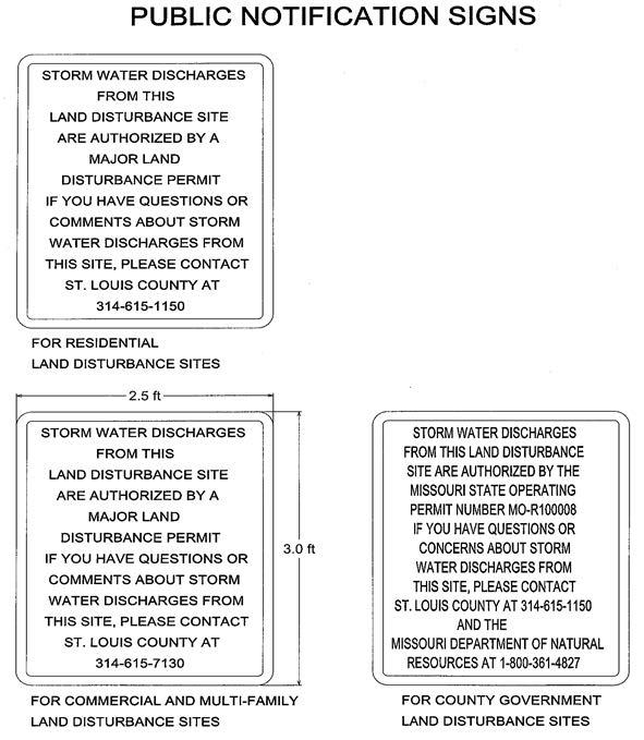
7/1/2018 Page 43 Sediment and Erosion Control Manual
PROCEDURE FOR RECEIVING WRITTEN AND VERBAL INFORMATION FROM THE
PUBLIC CONCERNING CONSTRUCTION SITES
1 ACRE AND ABOVE LOCATED IN UNINCORPORATED ST. LOUIS COUNTY, MISSOURI AND CONTRACTING MUNICIPALITIES
1) A public notification sign is to be placed on applicable construction sites before the start of construction. The sign shall be located to be plainly visible to the travelling public and as approved by the County. The sign shall be supplied, installed, maintained and removed by the contractor / developer. Additional sign information can be found in the Sediment and Erosion Control Manual.
2) Written information submitted by the public shall be recorded, copied, filed, date stamped, and then given to the construction site inspector for possible investigation and possible follow-up. When receiving verbal information from the public, the telephone contact or employee who receives the information in person, shall fill out a "Construction Site 1 Acre and Above Public Contact Form" The Form shall be recorded, copied, filed, and then given to the construction site inspector for possible investigation and possible follow-up. Inspectors conclusion shall be documented on the "Construction Site 1 Acre and Above Public Contact Form" and filed with the original written information (or a copy) to demonstrate acknowledgement and consideration of the information submitted. The inspector is required only to consider the information submitted, and may not need to follow-up and respond to every complaint or concern. If contact information is provided and if a response is required, it shall be sent to the resident in two weeks or less and a copy of the response will be kept on file and a copy shall be sent to the Storm Water Manager.
7/1/2018 Page 44 Sediment and Erosion Control Manual
UNINCORPORATED ST. LOUIS COUNTY, MISSOURI AND CONTRACTING MUNICIPALITIES
CONSTRUCTION SITE 1 ACRE AND ABOVE PUBLIC CONTACT FORM
Date: Name: Address: Telephone #: E-mail Address:
Location of Project (Include Street Name, Nearest Intersection, Address, Etc.):
Inquiry or Concern Regarding Construction Activities:
Date Construction Site Concern was Witnessed:
To Be Completed by the County: Inspector and Date Assigned: Permit Number:
Type of Site: Multi-Family Residential Commercial County Inspectors Conclusions:
Response Required: Yes No
The Inspector Shall Keep This Form, Response (If Required), Pictures and Other Info on File.
Send a Copy of All Information to the Storm Water Manager.
7/1/2018 Page 45 Sediment
Erosion Control Manual
and
SKETCH PLAN REQUIREMENTS FOR MAJOR LAND DISTURBANCE PERMIT
Purpose:
To allow land disturbance on legal lots prior to submission of a site plan or preliminary plat for development on the site, the proposed land disturbance should be compatible with development in the area, and the plan should reflect the minimal amount of land disturbance necessary until a site plan or preliminary plat is submitted for review. The sketch plan does not need to be sealed by a registered engineer or surveyor.
Sketch plan requirements for a Major Land Disturbance Permit shall include the following:
1) A locator number, address and zoning of the tract.
2) Existing contours.
3) A key map showing the tract in relationship to the surrounding area.
4) The approximate location of all existing structures and current uses within the tract and wooded areas within the tract and within one-hundred (100) feet thereof All historic buildings, as identified by the Historic Building Commission, should be identif ied.
5) The name, address, and phone number of the owners of the tract and the same for the permit applicant if different.
6) All existing roads and approximate location of wet and dry weather water courses, flood plain areas, sinkholes, and other physical features within the tract and within one hundred (100) feet thereof.
7) Approximate location of future uses including buildings and parking areas for commercial uses and lot lines / units for residential uses Proposed access to the site and proposed roads should be included. These features do not have to be to scale, but should clarify the relationship of future uses to the areas being cleared and grubbed.
8) The areas to be cleared and grubbed.
9) Phasing if any. (Required on thirty (30) acres or greater in size).
7/1/2018 Page 46 Sediment and Erosion Control Manual
SUBMISSION REQUIREMENTS OF THE DEPARTMENT OF PLANNING
Prior to the issuance of a Major Land Disturbance Permit, a land disturbance escrow must be filed with the Department of Planning.
The submission requirements of the St. Louis County Department of Planning are as follows:
1) Submit application
2) Submit four (4) copies of the sketch plan
3) Submit four (4) copies of the SWPPP (the sketch plan and SWPPP may be incorporated into one plan)
4) Subsequent to approval of SWPPP and prior to issuance of Land Disturbance Permit, submit Letter of Credit and Developer Agreement to the Department of Planning.
5) Naming St. Louis County as beneficiary in the form of cash, a letter of credit, or other improvement security in an amount deemed sufficient by the Department of Planning to cover all costs of improvements, landscaping, and maintenance of improvements for such period as specified by the Department of Planning. The land disturbance escrow shall include engineering and inspection costs sufficient to cover the cost of failure or repair of improvements installed on the site.
7/1/2018 Page 47 Sediment and Erosion Control Manual
APPENDIX "A"
COUNTY INSPECTIONS
General. The County Department(s) having enforcement authority and responsibilities described in the Code shall make inspections as herein required and shall either approve that portion of the work completed or shall notify the permit holder wherein the work fails to comply with the Land Disturbance, Sediment and Erosion Control Plan as approved Plans for land disturbance, stripping, excavating, and filling work bearing the stamp of approval of the County Department issuing the permit shall be maintained at the site during the progress of the work.
Exception. Inspections conducted by the St. Louis County Department of Transportation related to construction and maintenance of St. Louis County streets and roadways.
Extra Inspections. In addition to the inspections otherwise required, the Department(s) of Transportation and Public Works are authorized to perform and charge fees for extra inspections or reinspections which in their judgment are reasonably necessary due to non- compliance with the requirements of the Code, or work not ready or accessible for inspection when requested.
Verification of Permit Holder's Reports. The Department(s) of Transportation or Public Works may make extra inspections as deemed necessary to ensure the validity of the reports filed under the Code or to otherwise ensure proper installation, operation and maintenance of storm water Best Management Practices (BMPs) and to determine the overall effectiveness of the Storm Water Pollution Prevention Plan (SWPPP) and the need for additional control measures.
7/1/2018 Page 48 Sediment and Erosion Control Manual
POST-CONSTRUCTION STORM WATER MANAGEMENT IN NEW DEVELOPMENT AND REDEVELOPMENT
The Missouri Department of Natural Resources (MDNR), through the Small MS4 Permit (Permit), sets requirements for storm water management within the separate sewer portion of the St. Louis County area managed by the Metropolitan St. Louis Sewer District (MSD). The Permit also applies to all Urbanized Areas as defined in the latest census outside of MSD boundaries and inside St. Louis County. The St. Louis County Phase II Storm Water Management Plan (Plan) sets forth specific activities and schedules that the MSD, St. Louis County and its fifty-nine municipal co-permittee's must do to satisfy the Permit requirements.
The developer shall address the quality of long term storm water runoff from new development and redevelopment projects that disturb greater than or equal to one acre, including projects less than one acre that are part of a larger common plan of development or sale, that discharge into the St. Louis County, regulated small MS4. The developer shall ensure that controls are in place that have been designed and implemented to prevent or minimize water quality impacts by reasonably mimicking preconstruction runoff conditions on all affected new development projects and by effectively utilizing water quality strategies and technologies on all affected redevelopment projects, to the maximum extent practicable, emphasizing practices that reduce runoff volume The developer shall assess site characteristics at the beginning of the construction design phase to ensure adequate planning for storm water program compliance The purpose for this approach is to arrive at designs and practices that provide for most effective water quality treatment through infiltration, flow rates and similar site design opportunities All approved new construction or re-development, structural or non-structural, post construction, best management practices or devices including but not limited to rain gardens, vegetated open channels and stream buffers, drainage ditches, hydrodynamic separators and sand filters, which are intended to ensure clean water runoff from a development, will remain on the site after all construction is completed Treatment options may be required for water quality and channel protection in accordance with the most current MSD regulations. St. Louis County adopted the "Site Design Guidance" manual, developed by the MSD to assist the developer in implementing post construction storm water management requirements in the early stages (project planning) of a land development project.
Implementation of these BMPs in the plan area involves two different aspects due to the political jurisdictions in the plan area and the differing responsibilities of these authorities. One aspect is implemented by MSD through enforcement of design requirements for storm water management facilities, and the other is through land use controlled through the Planning and Zoning authorities of St. Louis County. In the plan area, all storm water facilities and controls must be reviewed and approved by MSD and all land use must concurrently be reviewed and approved by St. Louis County (or the applicable municipality). All commercial, residential, industrial and institutional owners of storm water facilities, including structural and non-structural BMPs, are required to maintain them as practical, and allowed and / or required by ordinance or other legal authority (other maintenance agreements may apply).
7/1/2018 Page 49 Sediment and Erosion Control Manual
STREAM BUFFER STANDARDS (In Part)
A stream buffer setback ordinance is a regulation that creates a "buffer zone" between a river, creek or stream, by specifying where construction of buildings and other infrastructure is or is not permitted A stream buffer ordinance will help avoid future liabilities by protecting new development and infrastructure from flood damage, while saving natural resources that provide multiple benefits Limiting development near stream banks will improve water quality, reduce erosion and sedimentation and protect riparian corridor habitat and greenways.
All land development activity requiring a site plan or Site Development Plan approved by the Department of Planning or the Planning Commission, except land used for agricultural or farming purposes, or regional pedestrian / bike trails, shall meet the following minimum standards for vegetated buffers for stream protection. Stream buffers in residential subdivisions containing 5 lots or m ore shall be in common ground. In large lot residential developments, single lot developments, and all other subdivisions the stream buffer may be in an easement.
1) For all natural waterways having a 100-year flood plain as depicted on the St. Louis County zoning maps, an undisturbed natural vegetative buffer shall be maintained for 50 feet, measured horizontally, on both banks (as applicable) of the stream as measured from the top of the stream bank. For all other natural waterways, an undisturbed natural vegetative buffer shall be maintained for 25 feet, measured horizontally, on both banks (as applicable) of the stream as measured from the top of the stream bank.
2) An additional 25-foot building setback, measured horizontally beyond the stream buffer, shall be required.
3) If any waterway is required or permitted to be enclosed, the requirements for buffers or additional building setbacks may be waived by the Director of Planning.
4) All plans and plats shall clearly show the boundaries of any stream buffers on a subject property and clearly indicate the types of natural vegetation to be retained, restored or removed from the buffer area.
5) The following structures, practices and activities are permitted in the stream buffer, with specific design or maintenance features, subject to review by the Director of Planning:
a) Roads, bridges and utilities (including sanitary and storm sewers). The right-of-way shall be the minimum width needed to allow for maintenance access and installation. The angle of the right-of-way or utility crossing shall be perpendicular as possible to the natural watercourse or stream buffer in order to minimize clearing requirements Plats and site plans shall include only the minimum number possible of such crossings.
b) Foot trails and paths.
6) Stream bank stabilization and stream buffer restoration projects approved by the Director of Planning are permitted within the vegetated buffer.
7) Water quality monitoring and stream gauging are permitted within the stream buffer.
7/1/2018 Page 50 Sediment and Erosion Control Manual
8) Trash and debris and individual trees within the stream buffer that are in danger of falling, causing damage to dwellings or other structures, or causing blockage of the natural watercourse may be removed.
After MSD has approved the applicable plans, the approved plans shall then be submitted to the St. Louis County Department of Transportation for review and final approval.
Additional Storm Water Quality Control Measures and Stream Buffers Standards can be found in Ordinance No. 23,553, located on the St. Louis County website.
7/1/2018 Page 51 Sediment and Erosion Control Manual
"KP" KARST PRESERVATION DISTRICT REGULATIONS (In Part)
An approximately four (4) square mile area of north St. Louis County located in the community of Old Jamestown is characterized by a unique karst topography It has been scientifically identified as the "Florissant Karst" region by the geologic / scientific community as being one of the finest examples of deep funnel-shaped sinkholes in the central United States.
Sinkholes, springs, and caves are among the common features in karst areas This type of topography presents serious constraints to urban development in particular soil creep near sinkhole depressions, localized flooding near sinkholes, and potential groundwater contamination from storm water runoff and sewage effluent A primary characteristic of this karst area is the existence of surface sinkholes into which all-surface runoff flows The area is considered to be internally drained, and as a result has no surface channels that convey surface runoff to larger surface streams.
This Karst Ordinance is therefore necessary to protect this significant natural environmental geologic area It is the purpose of this Karst Ordinance to preserve the Florissant Karst area in its natural state, while allowing development at an intensity that can be accommodated within the constraints of the geological features of this unique area.
1) No use or development in the "KP" Karst Preservation District shall:
a) Increase the surface runoff onto other properties.
b) Change the overall surface runoff pattern of the existing sinkhole network.
c) Create artificial routing of storm water between sinkholes.
d) Result in the blockage or filling of sinkholes.
e) Create or cause to be created artificial storm water structures within sinkholes.
f) Allow for the disposal of any materials into a sinkhole that will degrade the quality of water entering the subsurface through the sinkhole.
g) Decrease the rate that water enters the subsurface through the sinkhole.
h) Prevent the discharge of developed storm water into a sinkhole. Sinkholes are not adequate natural discharge points.
2) A geotechnical engineer shall submit a geotechnical report for most new development This report will be submitted to the St. Louis County Department of Transportation for review and approval, and, to insure compliance with this section and storm water design criteria as it pertains to Florissant Karst geology and proximity to sinkholes. A statement of compliance with this study, signed by the geotechnical engineer preparing the report, shall be included on any site plans The geotechnical engineer shall sign and seal all plans with a certification that the proposed construction will be completed in accordance with the grading and soils requirements and conditions contained in the report The Department of Transportation may require such additional data or engineering studies as may be necessary to determine the adequacy of the proposed plan for addressing storm water treatment.
Additional Karst Preservation District information pertaining to "Permitted Land Uses, Conditional Land Use and Development Permits, Accessory Land Uses" etc. can be found in Ordinance No. 23,925, located on the St. Louis County Council website archives
7/1/2018 Page 52 Sediment and Erosion Control Manual
AMENDED SOIL POST CONSTRUCTION BMP'S IN COUNTY RIGHT-OF-WAY
In conformance with the Missouri Clean Water Act, treatment measures for storm water runoff generated by impervious road improvements constructed within County right-of-way will be allowed on a limited basis within County right-of-way or easement. St. Louis County will permit only Amended Soils Post-Construction Storm Water Best Management Practices (BMPs) for storm water management within County right-of-way or easement. No BMPs other than Amended Soils BMPs will be considered for use in County right-of-way or easement. BMPs placed within County right-of-way or easement shall provide for the treatment of storm water run-off generated by pavement and / or sidewalk improvements constructed within County right-of-way only and shall not be used to treat storm water run-off from any other source. The project engineer shall provide a signed / sealed certification stating that the BMP meets all St. Louis County and MSD BMP standards and criteria and that the BMP is installed correctly in the field. The applicant shall install imbedded ground markers to locate the linear limits of the BMP in the field, and shall provide GPS coordinates to locate each marker for the future tracking and locating of BMP's. A separate BMP Special Use Permit shall be obtained from the St. Louis County Department of Transportation prior to the installation of any BMPs in St. Louis County right-of-way. Postconstruction storm water BMPs shall not be allowed within St. Louis County right-of-way or easement in subdivision developments or other developments with roads internal to the development. Information on the Amended Soils BMP can be found at the following MSD links:
www.stlmsd.com/what-we-do/stormwater-management/bmp-toolbox
www.stlmsd.com/what-we-do/stormwater-management/bmp-toolbox/ technology-matrix/amended-soils-disconnection-0
7/1/2018 Page 53 Sediment and Erosion Control Manual
DUST CONTROL
PHYSICAL DESCRIPTION - Control measures designed to reduce the transport of dust, thereby preventing pollutants from infiltrating into stormwater. Examples for construction activities include vegetative cover, wind barriers, minimization of soil disturbance, spray on adhesives, tilling, chemical treatment and water sprays.
In St. Louis County the contractor / permitee is required by Missouri State Law (10 CSR 10-6.170) and County Ordinance (612.340) to control fugitive dust blown from the construction site, land disturbance site, signal installation, etc. Dust control, including saw-cut material etc., on the construction site shall be monitored for safety purposes and to prevent nuisances The contractor / permitee shall apply reasonable measures to control dust and particulate matter (of any size or source) due to roadway / construction traffic, grading, clearing and grubbing, building demolition, wind erosion, saw-cutting etc. from migrating off the site of origin.
WHERE BMP IS TO BE INSTALLED - Critical in areas of exposed soil.
CONDITIONS FOR EFFECTIVE USE OF BMPs - A combination of the following actions should be used to help reduce the dust and air pollution at a construction site.
Minimize Concurrent Areas of Soil Disturbance - Phase work to the extent practical
Vegetative Cover - For areas not subjected to traffic, vegetation provides the most practical method of dust control and should be established as early as possible Temporary vegetation should also be used See Seeding and Sodding BMPs for additional information.
Sprinkling - The site can be sprinkled with water until the surface is moist. This practice is effective for dust control on large areas, haul routes or other traffic routes, but constant repetition is required for effective control.
Tilling - Roughen the surface and bring clods to the surface. This is an emergency measure that should be used before soil blowing starts. Begin tillage on windward side of the site. Chisel plows with shanks spaced about 12 inches to 18 inches apart and spring toothed harrows are examples of equipment that may produce the desired effect. See Surface Roughening BMPs for additional information.
Wind Barriers - Solid board fences, snow fences, burlap fences, crate walls and similar materials can be used to control air currents and blowing soil. Barriers placed at right angles to prevailing wind currents at intervals of about 10 times their height are effective in controlling soil blowing.
Street Cleaning - Paved areas that have soil on them from construction sites should be cleaned continuously, at least daily, utilizing a street sweeper or bucket type end loader or scraper.
Mulching - This practice offers a fast and effective means of controlling dust when properly applied Binders and tackifiers should be used on organic mulches Mulching is not recommended for areas with heavy traffic See Mulching BMP for additional information.
Note: If calcium chloride or spray-on adhesives are used for dust control, a permit may be required from the Missouri Department of Natural Resources.
7/1/2018 Page 54 Sediment and Erosion Control Manual
WHEN BMP IS TO BE INSTALLED - Routinely, especially in advance of and during periods of dry weather
INSTALLATION / CONSTRUCTION PROCEDURES - See conditions for effective use above
O&M PROCEDURES - Inspect daily and renew as needed
SITE CONDITIONS FOR REMOVAL - Maintain practices until all disturbed areas are vegetated or paved and blowing soil is no longer a concern.
TYPICAL DETAILS - Not applicable.
7/1/2018 Page 55 Sediment and Erosion Control Manual
EROSION CONTROL
PHYSICAL DESCRIPTION - An erosion control blanket is a preformed protective blanket of plastic fibers, straw or other plant residue designed to protect soil from the impact of precipitation and overland flow, and retain moisture to facilitate establishment of vegetation There are many products on the market designed for a variety of applications.
WHERE BMP IS TO BE INSTALLED - Typically installed on slopes or in channels prior to establishment of vegetation.
CONDITIONS FOR EFFECTIVE USE OF BMPs - Several factors, such as soil conditions, steepness and length of slope, depth of flow, runoff velocities, and time required to establish desired vegetation, influence the choice of product Manufacturer’s recommendations should be followed Products are available for a variety of uses:
Netting - Synthetic or natural fiber mesh installed over disturbed area to hold organic mulch and / or seed in place (806-90.11)
Temporary Erosion Control Blanket - Natural fiber blanket held together by netting to provide temporary erosion protection on slopes and channels (806-90.10)
Permanent Erosion Control Blanket - Synthetic blanket material which provides permanent erosion control on slopes and channels with increased water flow velocities (806-20.00)
Turf Reinforcement Mat - 3-dimensional permanent synthetic mat that provides a matrix to greatly reinforce the root system of the desired vegetation for permanent erosion protection in high flow channels and on critical slopes. (See page 58 for additional information on TRMs)
For additional information see Section 806.90 of St. Louis County's Standard Specification for Road and Bridge Construction.
WHEN BMP IS TO BE INSTALLED - Dependent upon intended use - immediately after completion of a phase of grading, or installation of vegetation.
INSTALLATION / CONSTRUCTION PROCEDURES - Follow manufacturer's recommendations and specifications, particularly noting requirements for check slots, fastening devices and need for firm contact with soil.
O&M PROCEDURES
Inspect every week and after every storm until adequate vegetation is established.
Repair erosion and / or undermining at top of slope
Repair undermining beneath blankets - pull back the blanket(s), fill and compact eroded area, revegetate and then secure blanket(s) firmly
Reposition or replace blankets that have moved along the slope or channel and secure firmly
Replace damaged blankets.
SITE CONDITIONS FOR REMOVAL - Temporary blankets will generally degrade naturally; permanent blankets remain in place
TYPICAL DETAILS - Not applicable
7/1/2018 Page 56 Sediment and Erosion Control Manual
PERMANENT EROSION CONTROL GEOTEXTILE REQUIREMENTS
SCOPE - This specification covers the material requirements and methods of testing geosynthetic materials used between energy absorbing armor systems and the in situ soil to prevent soil loss resulting in excessive scour and to prevent hydraulic uplift pressures causing instability. This specification applies to standard detail numbers 806-35.00, 806-40.02, 806-40.03, 806-40.04, 80655.10, 806-55.12 and 806-55.18b. The following Geotextile Structure Types are evaluated in this specification:
1) Needle-Punched - Non-Woven (NP - NW)
2) Heat bonded - Non-Woven (HB - NW)
3) Monofilament - Woven (MF - W)
4) Multifilament - Woven (MuF - W)
5) Combination Monofilament / Fibrillated Yarn - Woven (C - W)
6) Recycled / Reinforced Needle-Punched - Non-Woven (R/R NP - NW)
7) Circular - Woven (Cir - W)
GENERAL - The Geotextile Class is from Table 1 of AASHTO M 288. The Department's evaluation of geotextiles submitted will be based on the following tests:
1) Soil Retention - The test to evaluate this characteristic will be performed in accordance with the apparent opening size test, ASTM D4751.
2) Flow Capacity - The test to evaluate this characteristic will be performed in accordance with the permittivity test, ASTM Method D4491.
3) Tensile Strength - The tests to evaluate this characteristic will be performed in accordance with the following:
a) Grab test method, ASTM D4632.
b) Trapezoid tear test method, ASTM D4533.
c) Static puncture strength using a 2-inch probe, ASTM D6241
4) Apparent Opening Size (AOS) - Test method, ASTM D 4751.
5) UV Resistance (at 500 hours) - Test method ASTM D 4355 minimum retained strength of 50 percent.
7/1/2018 Page 57 Sediment and Erosion Control Manual
The following products, while not a complete list, are approved for use:
• Mirafi® 180N
• Mirafi® FW 500
• Mirafi® S1600
• Propex® Geotex® 104F
• Propex® Geotex® 701, 801
• Carthage Mills® FX-400TF
• Carthage Mills® FX-400HS
7/1/2018 Page 58 Sediment and Erosion Control Manual
Minimum Strength Requirements Stabilization Requirements Maximum Apparent Opening Size Minimum Permitivity (sec-1) Geotextile Structure Type Class Percent Elongation (%) Grab Strength (lbf) Tear Strength (lbf) Puncture Strength (lbf) Sieve Size (in.) Sieve Designation MF-W 2 < 50 (W) 202 79 433 0.0117 No. 50 0.5 All others 1 ≥ 50 (NW) 315 112 618
Table 1 - Geotextile Class
TURF REINFORCEMENT MAT (TRM)
This section is intended to provide general guidelines for the installation of TRMs and does not supersede manufacture's guidelines. The following sections summarize the general, accepted procedures for installation of TRMs and provide basic guidance for slope and channel installations. Detailed design / installation information should be obtained from the manufacturer.
The following are required for installation:
• The contractor or consultant shall submit appropriate hydraulic calculations for assessing the appropriate product and installation method for the site.
• The manufacturer's installation instructions shall be submitted for permit approval.
• The manufacturer's installation instructions shall be part of the SWPPP.
• The manufacturer's installation instructions shall be on site at all times.
GENERAL PROCEDURE - Prepare a stable and firm soil surface free of rocks and other obstructions. Apply soil amendments as necessary to prepare seedbed. Place fertilizer, water, and seed in accordance with manufacturer, local / state regulations, or engineer / specifier requirements. Typically, TRMs are unrolled parallel to the primary direction of flow. Ensure the product maintains intimate contact with the soil surface over the entirety of the installation. Do not stretch or allow material to bridge over surface inconsistencies. Staple / stake TRMs to soil such that each staple / stake is flush with underlying soil. Install anchor trenches, seams and terminal ends as specified.
Install TRMs after application of seed, fertilizer, mulches (if necessary) and other necessary soil amendments, unless soil in-filling of the TRM is required. For TRMs if soil in-filling, install TRM, apply seed, and other soil amendments lightly brush or rake 0.3 to 0.7 inches of topsoil into TRM matrix to fill the product thickness. If in filling with a hydraulically applied matrix or medium is required; install TRM, then install hydraulically applied matrix or medium at the manufacturer's suggested application rate.
ANCHOR TRENCHES, SEAMS AND TERMINAL ENDS
1) UPSLOPE ANCHOR - Utilize one of the methods detailed below for initial anchoring of TRMs:
a) Staples - Install the TRM 3 feet beyond the shoulder of the slope onto flat final grade. Secure roll end with a single row of stakes/staples on 1-foot centers.
b) Anchor Trench - Excavate a 6 inch by 6 inch anchor trench. Extend the upslope terminal end of the TRM 3 feet past the anchor trench. Use stakes or staples to fasten the product into the bottom of the anchor trench on 1-foot centers. Backfill the trench and compact the soil into the anchor trench. Apply seed and any necessary soil amendments to the compacted soil and cover with remaining 1-foot terminal end of the TRM. Fold product over compacted soil in anchor trench to overlap downslope material. Secure terminal end of TRM with a single row of stakes or staples on 1-foot centers.
c) Staple Check - Construct a stake / staple check slot along the top edge of the TRM by installing two rows of staggered stakes / staples 4 inches apart on 4-inch centers.
7/1/2018 Page 59 Sediment and Erosion Control Manual
d) Single Net Product Anchor Trench - Excavate a 6 inch by 6 inch anchor trench. Position roll such that the leading end of the roll is downslope and upside down. Apply seed and necessary soil amendments. Extend product 1-foot downslope of anchor trench and place material in anchor trench (upside down). Secure terminal end and material in anchor trench with staples at 1-foot intervals. Fill anchor trench with soil and compact. Apply seed and necessary soil amendments to fill placed in anchor trench. Move remaining roll over and downslope of anchor trench and proceed unrolling TRM downslope (since roll was initially reversed, folding material over anchor trench will result in the net side up, and rolling correctly downslope over the anchor trench).
2) SEAMS - Utilize one of the methods detailed below for seaming of TRMs:
a) Adjacent Seams - Overlap edges of adjacent TRMs by 2 to 4 inches or by abutting products as defined by manufacturer. Use a sufficient number of stakes or staples to prevent seam or abutted rolls from separating.
b) Consecutive Rolls - Shingle and overlap consecutive rolls 2 to 6 inches in the direction of flow. Secure staples through seam at 1-foot intervals.
c) Check Seam - Construct a stake / staple check seam along the top edge of TRM for slope application and at specified intervals in a channel by installing two staggered rows of stakes / staples 4 inches apart on 4-inch centers.
d) Slope Interruption Check Slot - Excavate a trench measuring 6 inches wide by 6 inches deep. Secure product to the bottom of the trench. Fold product over upslope material and fill and compact the trench on the downslope side of check slot and seed fill. Continue rolling material downslope over trench.
3) TERMINAL ENDS - Utilize one of the methods detailed below for all terminal ends of TRMs:
a) Staples - Install the TRM 3 feet beyond the end of the channel and secure end with a single row of stakes / staples on 1-foot centers. Stakes / staples for securing TRMs to the soil are typically 6 inches long.
b) Anchor Trench - Excavate a 6 inch by 6 inch anchor trench. Extend the terminal end of the TRM 3 feet past the anchor trench. Use stakes or staples to fasten the product into the bottom of the anchor trench on 1-foot centers. Backfill the trench and compact the soil into the anchor trench. Apply seed and any necessary soil amendments to the compacted soil and cover with remaining 1-foot terminal end of the TRM Secure terminal end of TRMs with a single row of stakes or staples on 1-foot centers.
c) Check Slot - Construct a stake / staple check slot along the terminal end of the TRM by installing two rows of staggered stakes/staples 4 inches apart on 4-inch centers.
SLOPE INSTALLATIONS - At the top of slope, anchor the TRMs according to one of the method detailed in Section 1. Securely fasten all TRMs to the soil by installing stake / staple pattern and length in accordance with the manufacturer's requirements for the site specific flow rates and soil conditions For adjacent and consecutive rolls of TRMs follow seaming instructions detailed in Section 2. The terminal end of the TRM installation must be anchored using one of the methods detailed in Section 3
7/1/2018 Page 60 Sediment and Erosion Control Manual
CHANNEL INSTALLATIONS - Construct an anchor trench at the beginning of the channel across its entire width according to Section 1b. Follow the manufacturer's installation guidelines in constructing additional anchor trenches or stake / staple check slots at intervals along the channel reach and at the terminal end of the channel, according to Section 1. Unroll TRMs down the center of the channel in the primary water flow direction. Securely fasten all TRMs to the soil by installing stake / staple pattern and length in accordance with the manufacturer's requirements for the site specific flow rat es and soil conditions Significantly higher anchor rates and longer stakes / staples may be necessary in sandy, loose, or wet soils and in severe applications. For adjacent and consecutive rolls of TRMs, follow seaming instructions detailed in Section 2. All terminal ends of the TRMs must be anchored using one of the methods detailed in Section 3.
With any TRM installation, ensure sufficient staples to resist uplift from hydraulics, wind, mowers, and foot traffic. For the most effective installation of TRMs, use stake / staple patterns and densities as recommended by the manufacturer.
Repair any damaged areas immediately by restoring soil to finished grade, re-applying soil amendments and seed, and replacing the TRMs
SHORELINE INSTALLATIONS - When required, lower the waterline as necessary and construct an anchor trench at the top of slope as described in Section 1b. Unroll the product down the slope and follow the manufacturer's installation guidelines in constructing additional anchor trenches or stake/staple check slots at intervals along the shoreline. Construct an anchor trench just below the mean water line at the terminal end of the shoreline, according to paragraph 3b Securely fasten all TRMs to the soil by installing stake / staple pattern and length in accordance with the manufacturer's requirements for the site specific flow rates and soil conditions Significantly higher anchor rates and longer stakes / staples may be necessary in sandy, loose, or wet soils, below the waterline and in severe applications. For adjacent and consecutive rolls of TRMs, follow seaming instructions detailed in Section 2
7/1/2018 Page 61 Sediment and Erosion Control Manual Gradient 4:1 Slope 3:1 Slope 2:1 Slope 1:1 Slope Slope Length (feet) 25 50 75 100 125 150 175 200 225 250 275 300 Typical Staple Quantities: 0.7 - 1.2 yd2 1.2 - 1.7 yd2 1.7 - 3.8 yd2
Flow Conditions Low Flow Channel < 2.1lbs/ft2 High Flow Channel > 2.1lbs/ft2 Length (feet) 25 50 75 100 125 150 175 200 225 250 275 300 Typical Staple Quantities: 2.9 - 3.4 yd2 3.0 - 4.1 yd2
Table 1 - Standard Specifications for Turf Reinforcement Mat (TRM) Products
For applications where vegetation alone will not sustain expected flow and/or provide sufficient longterm erosion protection.
Permanent1 - All Categories of TRM's must have a minimum thickness of 0.25 inches per ASTM D 6265 and UV stability of 80% per ASTM D 4355 (500 hours exposure).
Turf Reinforcement Mat (TRM) - a rolled erosion control product composed of nondegradable synthetic fibers, filaments, nets, wire mesh and/or other elements, processed into a permanent, threedimensional matrix of sufficient thickness. TRM's, which may be supplemented with degradable components, are designed to impart immediate erosion protection, enhance vegetation establishment and provide long-term functionality by permanently reinforcing vegetation during and after maturation (Note: TRMs are typically used in hydraulic applications, such as high flow ditches and channels, steep slopes, stream banks, and shorelines, where erosive forces may exceed the limits of natural, unreinforced vegetation or in areas where limited vegetation establishment is anticipated.)
1 For TRMs containing degradable components, all property values must be obtained on the non-degradable portion of the matting alone.
2 Minimum Average Roll Values, machine direction only for tensile strength determination using ASTM D 6818 (Supersedes Mod. ASTM D 5035 for RECP's).
3 Field conditions with high loading and/or high survivability requirements may warrant the use of a TRM with a tensile strength of 3,000 lbs./ft. or greater.
4 Required minimum shear stress TRM (fully vegetated) can sustain without physical damage or excessive erosion (> 0.5 inch soil loss) during a 30-minute flow event in large scale testing.
5 Acceptable large-scale testing protocol may include ASTM D 6460, or other independent testing deemed acceptable by the engineer.
7/1/2018 Page 62 Sediment and Erosion Control Manual
Type Product Description Material Composition Slope Applications Maximum Gradient Channel Applications Maximum Shear Stress4,5 Minimum Tensile Strength2,3
Turf Reinforcement Mat
1.A
0.5:1 (H:V) 6.0 lbs./ft2 125 lbs./ft. 1.B Turf Reinforcement Mat 0.5:1 (H:V) 8.0 lbs./ft2 150 lbs./ft. 1.C Turf Reinforcement Mat 0.5:1 (H:V) 10.0 lbs./ft2 175 lbs./ft.
HYDRAULIC EROSION CONTROL PRODUCT (HECP)
SUMMARY - A Hydraulic Erosion Control Product (HECP) is a manufactured, temporary, degradable, pre-packaged fibrous material that is mixed with water and hydraulically applied as a slurry designed to reduce soil erosion and assist in the establishment and growth of vegetation. The HECP will achieve maximum performance after a sufficient curing period, which will vary based upon site specific conditions. The HECP forms a protective layer which controls erosion and allows for enhanced seed germination and accelerated plant growth. HECP is sometimes referred to by different names such as Bonded Fiber Matrix (BFM), hydro mulch, etc.
SUBMITTALS - Submit manufacturer's product data and installation instructions. In addition, submit a letter from the manufacturer certifying that the HECP meets or exceeds all performance properties and packaging requirements found in this specification.
PACKAGING, DELIVERY, STORAGE, AND HANDLING - Deliver materials and products in ultra violet (UV) and weather resistant factory labeled packages. Store and handle in strict compliance with manufacturer's instructions and recommendations. Protect product from damage due to climatic conditions and construction operations.
PERFORMANCE REQUIREMENTS
The HECP to be used shall meet the performance standards as specified in Table 1 below Table
1 This table is for general guidelines only Refer to manufacturer for application rates, instructions, gradients, maximum continuous slope lengths and other site specific recommendations
2 These categories are independent of rolled erosion control products (RECPs) categories, despite the identical names
3 A manufacturer's estimated time period, based upon field observations, that a material can be anticipated to provide erosion control as influenced by its composition and site-specific conditions
4 "C" Factor calculated as ratio of soil loss from HECP protected slope (tested at specified or greater gradient, H:V) to ratio of soil loss from unprotected (control) plot based on in large-scale testing.
5 Acceptable large-s cale test methods may include ASTM D 6459, or other independent testing acceptable to the engineer.
6 Minimum vegetation establishment is calculated as outlined in ASTM D 7322 being a perc entage by dividing the plant mass per area of the protected plot by the plant mass per area of the control plot
7/1/2018 Page 63 Sediment and Erosion Control Manual
1 - Performance Chart for Standard HECPs Hydraulic Erosion Control1 Typical Application Typical Maximum Slope Maximum Uninterrupted Maximum Minimum Type2 Term Functional Rates Gradient Slope Length C Factor4,5 Vegetation Longevity3 Pounds per Acre H:V Feet 3:1 Test Establishment6 1 Ultra-Short Term 1 month 1500 – 2500 < 4.0:1 20 0.75 150 % 2 Short Term 2 months 2000 – 3000 < 3.0:1 25 0.50 150 % 3 Moderate Term 3 months 2000 – 3500 < 2.0:1 50 0.15 200 % 4 Extended Term 6 months 2500 – 4000 < 1.0:1 75 0.10 300 % 5 Long Term 12 months 3000 – 4500 < 0.5:1 100 0.02 400 %
SUBSTRATE AND SEEDBED PREPARATION - Examine substrates and conditions where HECP will be applied. Apply HECP to geotechnically stable slopes that have been designed and constructed to divert runoff away from the face of the slope. Repair any pre-existing rills or gullies and roughen slope if possible by track-walking or using some other imprinting device. If necessary to reduce slope length in accordance with Table 1, install Fiber Rolls and Wattles, or other slope interruption devices perpendicular to the water flow. Do not proceed with installation until satisfactory conditions are established.
APPLICATION
1) Strictly comply with manufacturer's application instructions, machinery requirements and other recommendations. For optimum pumping and application performance use approved hydraulic seeding/mulching machines with an appropriate nozzle tip. Apply HECP from opposing directions to achieve best soil coverage reducing the "shadow effect".
2) Fill the tank of the hydraulic machine approximately ⅓ full with water. Continue to add water slowly while adding HECP at a steady rate. Utilize the HECP manufacturer's recommended water-to-HECP ratio. Confirm loading rates with equipment manufacturer. All HECP and supplemental materials should be loaded into the tank before it is approximately ¾ full. Finish filling the tank with water to the desired level. Uniform slurries may require agitation or mixing for a minimum of 10 minutes after all of the water and HECP are in the tank.
3) Mix and apply HECP over the prepared substrate. Best performance is achieved when HECP is applied to unsaturated soils or substrates and allowed to undergo an appropriate curing period.
4) Use an appropriate nozzle tip to ensure uniform soil surface coverage. Hose applications may be required for certain sites and locations. Application rates of HECP shall follow minimum rates found in Table 1, and meet manufacturer's specific guidelines for proper performance.
5) HECP is not intended to be applied in channels, swales or other areas where concentrated flows are anticipated, unless installed in conjunction with Rolled Erosion Control Products (RECPs).
6) After application, thoroughly flush the tank, pumps and hoses to remove all HECP material. Wash all material from the exterior of the machine and remove any slurry spills. Once dry, HECP will be more difficult to remove from equipment.
PROTECTION - Areas treated with HECP shall be protected from foot and vehicle traffic, grazing and other disturbances. Any damaged area shall be repaired utilizing the exact blend and application procedure as specified above.
WHERE BMP IS TO BE INSTALLED - Typically installed on slopes where erosion control blankets are impractical and other mulching methods are inadequate.
CONDITIONS FOR EFFECTIVE USE OF BMPs - Type of Flow: Sheet flow only.
WHEN BMP IS TO BE INSTALLED - Immediately after completion of a phase of grading.
7/1/2018 Page 64 Sediment and Erosion Control Manual
INSTALLATION / CONSTRUCTION PROCEDURES - Follow manufacturer's recommendations to maximize usefulness.
OPERATION & MAINTENANCE PROCEDURES
Inspect every week and after every storm until vegetation is fully established.
Repair eroded areas and reapply product and vegetation.
SITE CONDITIONS FOR REMOVAL - Typically left in place to degrade naturally.
TYPICAL DETAILS - Not applicable.
7/1/2018 Page 65 Sediment and Erosion Control Manual
MULCH
PHYSICAL DESCRIPTION - A layer of organic material designed to protect exposed soil or freshly seeded areas from erosion by eliminating direct impact of precipitation and slowing overland flow rates. Mulch materials may include, but are not limited to, such things as grass, hay, straw, wood chips, wood fibers, hydro mulch and shredded bark. Type 1 mulch is prohibited in the flood plain.
• Type I Mulch-Vegetative (includes grass, hay, and straw)
• Type II Mulch-Vegetative with asphalt emulsion (includes grass, hay, and straw)
• Type III Mulch-Vegetative with overspray (includes grass, hay, and straw).
• Type V Mulch-Hydro mulch (includes wood fiber, wood cellulose).
• Shredded Hardwood Bark Mulch
• Wood Chips, (not recycled lumber).
WHERE BMP IS TO BE INSTALLED - Typically installed on seeded areas for temporary use, and in landscaped areas for permanent use
CONDITIONS FOR EFFECTIVE USE OF BMPs
Type of Flow: Sheet flow only
Slopes: See attached chart for types of mulch acceptable as a function of slope length and steepness
Mulching Rates: See attached table
WHEN BMP IS TO BE INSTALLED - Immediately after grading landscaped areas or seeding other areas.
INSTALLATION / CONSTRUCTION PROCEDURES
Install upstream BMPs to protect area to be mulched
Rough grade area and remove all debris larger than 1 inch if area is to be vegetated and mowed in the future, larger than 2 inches if area is to be permanently mulched
If area is to be seeded, follow requirements of Seeding BMP
Spread mulch and anchor by punching it into the ground, using netting, peg and twine, or tacking with liquid binder
For additional information see Section 802 of St. Louis County's Standard Specifications for Road and Bridge Construction.
O&M PROCEDURES
Inspect every week and after every storm until adequate vegetation is established; annually for permanent mulch
Protect from vehicular and foot traffic
Repair damaged, degraded or eroded areas - reseed as needed and replace mulch
SITE CONDITIONS FOR REMOVAL - Temporary mulch should be removed when adequate vegetation is established
TYPICAL DETAILS - Type of mulch required for various slopes and application rates attached
7/1/2018 Page 66 Sediment and Erosion Control Manual
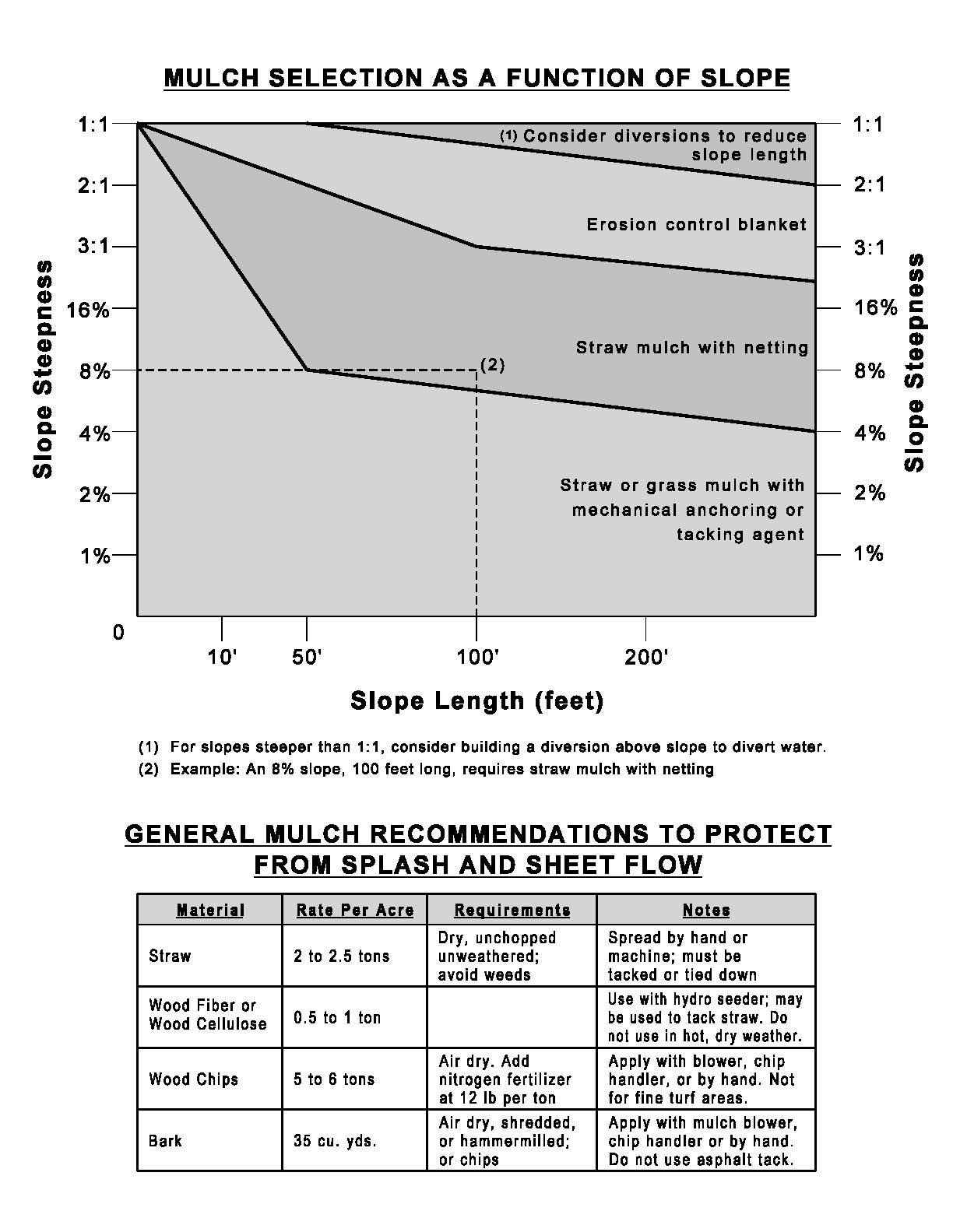
7/1/2018 Page 67 Sediment and Erosion Control Manual
ROCK OUTLET / EMBANKMENT PROTECTION / PAVED DITCH
PHYSICAL DESCRIPTION - A rock apron installed over a geotextile fabric at a point of concentrated discharge, designed to slow the velocity of flow and protect the receiving area from erosion.
Follow guidelines shown in the St. Louis County Standard Specifications for Road and Bridge Construction concerning use of related BMP's such as:
• Light Stone Revetment;
• Heavy Stone Revetment;
• Articulating Cellular Concrete Erosion Control System;
• Concrete Slope Protection;
• Gabions;
• Reno Mattresses;
• Type 2 Rock Blanket;
• Ditch Liner;
• Rock Lining.
WHERE BMP IS TO BE INSTALLED - Installed at BMP outlets, for example, at the end of pipe slope drains, the emergency overflow or outlet pipe of a sediment basin.
CONDITIONS FOR EFFECTIVE USE OF BMPs
Type of Flow: Concentrated flow
Flow at Outlet: Maximum velocity of 10 fps
WHEN BMP IS TO BE INSTALLED - With the construction of the upstream BMP that creates the concentrated discharge.
INSTALLATION / CONSTRUCTION PROCEDURES
Grade subgrade of rock blanket to required section.
Place filter fabric, providing enough slack to assure that rock will not tear the fabric when it is placed.
Install rock with uniform profile and cross section.
O&M PROCEDURES:
Inspect every week and after every storm during construction.
Remove sediment and trash accumulation
Replace displaced rock - larger rock may be required.
Stabilize eroded areas - extend if necessary
7/1/2018 Page 68 Sediment and Erosion Control Manual
SITE CONDITIONS FOR REMOVAL - Removed concurrently with upstream BMPs Some may be left as a permanent post construction BMP as shown on approved plans or in the permit
TYPICAL DETAIL
The Design Criteria Manual includes standard drawing numbers:
• C609.15 - Paved Ditches and Gutters
• C611.50 - Heavy Stone Revetment Ditch Liner
• C611.60 - Concrete Slope Protection
• C611.70 - Gabion Walls
7/1/2018 Page 69 Sediment and Erosion Control Manual
SEEDING
PHYSICAL DESCRIPTION - Establishment of vegetation by spreading grass seed designed to protect exposed soil from erosion by eliminating direct impact of precipitation and slowing overland flow rates. Once established, the vegetative cover will also filter pollutants from the runoff Use only perennial vegetation for final stabilization.
WHERE BMP IS TO BE INSTALLED - To exposed soil after a phase of rough or finish grading has been completed, or areas where no activity will occur for 30 days
CONDITIONS FOR EFFECTIVE USE OF BMPs
Type of Flow: Sheet flow
Contributing Slope Length: 30 foot maximum for 3:1 slopes
50 foot maximum for slope between 3:1 and 10:1
100 foot maximum for slopes under 10%
Minimum Rates: See attached chart(s)
Acceptable Dates: See attached chart
WHEN BMP IS TO BE INSTALLED - Immediately after rough or finished grading is completed.
INSTALLATION / CONSTRUCTION PROCEDURES
Install upstream BMPs to protect area to be seeded.
Rough grade area and remove all debris larger than 1-inch in diameter and concentrated areas of smaller debris.
Install stabilization grids, if needed.
Mix soil amendments (lime, fertilizer, etc.) into top 3 to 6 inches of soil as needed.
Plant seed ¼ to ½ inch deep.
Roll lightly to firm surface.
Cover seeded area with mulch unless seeding completed during optimum spring and summer dates.
Install additional stabilization (netting, bonded fiber matrix, etc.) as required
Water immediately - enough to soak 4 inches into soil without causing runoff.
If contract / permit allows seeding to be used for final stabilization, only perennial vegetation seeds shall be used.
For additional information see Sections 805 and 806.50 of St. Louis County's Standard Specification for Road and Bridge Construction.
O&M PROCEDURES:
Inspect every week and after every storm
Protect area from vehicular and foot traffic
Reseed areas that have not sprouted within 21 days of planting.
Repair damaged or eroded areas and reseed and stabilize as needed
Do not mow until 4 inches of growth occurs
During the first 4 months, mow no more than ⅓ the grass height
Re-fertilize during 2nd growing season
SITE CONDITIONS FOR REMOVAL - Does not require removal, but temporary seeding can be removed immediately prior to work returning to an area
7/1/2018 Page 70 Sediment and Erosion Control Manual
SEEDING REQUIREMENTS
O = Optimum seeding dates
A = Acceptable seeding dates
P = Permitted seeding dates with reseeding 2 months later - Initially use 50% of seed and 75% of fertilizer. Reseed with additional 75% seed and remaining fertilizer.
Mixture # 1 = Tall Fescue @ 150 pounds per acre and Brome @ 100 pounds per acre.
Mixture # 2 = Tall Fescue @ 100 pounds per acre; Perennial Rye grass @ 100 pounds per acre; and Kentucky Blue grass @ 10 pounds per acre.
* = Seeding rate for slopes in excess of 20% (5:1), shall be 10 pounds per 1000 sq. ft.
ENM = Effective neutralizing material per State evaluation of quarried rock.
7/1/2018 Page 71 Sediment and Erosion Control Manual
Dates for Seeding Permanent Seeding Jan Feb March April May June July Aug Sep Oct Nov Dec Tall Fescue O O O O O Smooth Brome O O O O O Fescue & Brome O O O O O O Fescue, Rye & Bluegrass A A O O O P P O O P P A Temporary Seeding Jan Feb March April May June July Aug Sep Oct Nov Dec Rye or Sudan A A O O O O O O O O A A Oats A O O O O O O O
Fertilizer
Permanent Seeding* Pounds per acre Pounds Per 1000 sq. ft. Tall Fescue 300 7.0 Smooth Brome 200 4.6 Mixture # 1 250 5.7 Mixture # 2 210 4.8
Minimum
and Seeding Rates
Temporary Seeding Pounds per acre Pounds Per 1000 sq. ft. Rye or Sudan 150 3.5 Oats 200 2.5 Permanent Seeding Temporary Seeding Fertilizer (pounds per acre) (pounds per acre) Nitrogen 45 30 Phosphate 65 30 Potassium 65 30 Lime - ENM 600 600
TYPICAL DETAILS - Minimum seeding rates and acceptable dates for work attached.
INSTALLATION / CONSTRUCTION PROCEDURES
Excavate diversion area except for area of upstream connection
Compact as required to place diversion properly
Install pipe bedding or channel lining as required.
7/1/2018 Page 72 Sediment and Erosion Control Manual
SODDING
PHYSICAL DESCRIPTION - A ¾ inch to 1-inch thick mat of vigorous turf, free of disease, insects and weeds. Sod prevents raindrops from disrupting the soil structure and causing erosion. Sod slows water runoff and acts as a filter when sediment-laden runoff crosses over the sodded area.
WHERE BMP IS TO BE INSTALLED - Typically installed in areas requiring immediate erosion protection, such as swales or detention ponds and as filter strips, around inlets, and adjacent to curbs. Also installed in areas requiring immediate aesthetic appearance or f unction such as entrances to new subdivision and off site construction areas.
CONDITIONS FOR EFFECTIVE USE OF BMPs - Type of Flow: Sheet flow and low concentrated flows with velocities less than 5 fps.
WHEN BMP IS TO BE INSTALLED - Immediately after finish grading, installation of area inlets, and installation of underground services and foundations of new homes.
INSTALLATION / CONSTRUCTION PROCEDURES
Finish grade area and remove all debris larger than ½ inch in diameter and concentrated areas of smaller debris.
Soil preparation of area to be sodded shall be determined by tests to determine lime and fertilizer requirements. Soil amendments shall be mixed into top 3 to 6 inches of soil by disking or other means.
Level and roll soil lightly to provide an even grade and firm the surface. Soil should not be excessively wet or dry.
Lay first row of sod perpendicular to the slope or direction of flow. Butt subsequent rows tight against previous rows with strips staggered in brick -like pattern. Fill minor gaps with good soil and roll entire surface to ensure contact.
Stake, staple and / or net corners and centers of sod strips as required.
Water immediately after installation enough to soak 4 inches into soil without causing runoff.
For additional information see Section 803 of St. Louis County's Standard Specification for Road and Bridge Construction.
Type of sod shall be as specified in the contract or on the approved plans.
O&M PROCEDURES:
Water sod daily for 3 weeks - enough to soak 4-inches into soil without causing runoff.
Reposition areas of sod that has moved along the slope.
Remove sediment accumulations - replace sod if necessary.
Repair any eroded areas, replace sod, and stabilize as needed.
Do not mow until 3-inches of new growth occur. During the first 4 months, mow no more than ⅓ the grass height.
SITE CONDITIONS FOR REMOVAL - Not applicable.
TYPICAL DETAIL - 803-10.00
7/1/2018 Page 73 Sediment and Erosion Control Manual
SOIL BINDERS
PHYSICAL DESCRIPTION - A material sprayed onto the surface of exposed soils designed to protect against erosion for wind or runoff. The useful life of most products is 3 to 6 months. Examples of materials used include vegetable-based adhesives, copolymers, petroleum oils and resin-emulsions.
WHERE BMP IS TO BE INSTALLED - Typically used in disturbed areas and in combination with other BMPs such as perimeter controls, seeding or mulching.
CONDITIONS FOR EFFECTIVE USE OF BMPs - Type of Flow: Sheet flow.
WHEN BMP IS TO BE INSTALLED - Immediately after completion of a phase of grading.
INSTALLATION / CONSTRUCTION PROCEDURES - Follow manufacturer's recommendations to maximize usefulness and avoid formation of pools or impervious areas where stormwater cannot infiltrate.
O&M PROCEDURES
Inspect every week for damage from vehicles, runoff, or freeze-thaw conditions.
Reapply product or utilize additional BMPs
SITE CONDITIONS FOR REMOVAL - Typically left in place to degrade naturally.
TYPICAL DETAILS - Not applicable.
7/1/2018 Page 74 Sediment and Erosion Control Manual
STREAM BANK PROTECTION
PHYSICAL DESCRIPTION - A vegetative, structural or combination treatment of streams designed to stabilize the stream and reduce erosion. It is important to note that a systemic analysis of the entire reach of stream must be conducted in order to avoid unintended negative impacts on a stream as a result of a corrective action at an isolated location. A wide array of products and methodologies can be used to stabilize streams: live stakes; cellular confinement matrices; articulated block pavers; rip rap; gabion baskets; turf reinforcement mats; fabric formed revetments; cedar tree revetments; straw wattles; grade control structures; stilling basins; etc.
WHERE BMP IS TO BE INSTALLED - Open channels downstream from developed areas.
CONDITIONS FOR EFFECTIVE USE OF BMPs - Acceptable methods vary widely due to the unique nature of each reach of channel. Design considerations include: current and future watershed conditions; discharge; velocity; sediment load; channel slope; control of bottom scour (incising); soil conditions; compatibility with other improvements; changes in channel alignment; and protection and maintenance of fish and wildlife habitats and existing tree canopy.
WHEN BMP IS TO BE INSTALLED - Well in advance of disturbing any upstream areas in order to give plant material a relatively long period to become established and allow ample time for inspection and necessary repairs during construction of the remainder of the development.
INSTALLATION / CONSTRUCTION PROCEDURES - Procedures are specific to materials used. General construction principles include:
Stabilize the channel bottom first to prevent incising and knickpoints from undermining the bank protection.
Start and stop bank protection at stable points along the channel.
Minimize the size of all disturbed areas and stabilize as soon as each phase of construction is complete.
Use other BMPs to prevent runoff from disturbing the stream bank protection area until it has been completed.
Store all construction materials well away from the stream.
At the end of each workday, move all construction equipment out of and away from the stream to prevent flooding.
Avoid steep slopes on the stream bank.
Fence the construction area and post warning signs if trespassing or vandalism is likely.
O&M PROCEDURES
Inspect every week and after every storm during construction; and once each season thereafter.
Repair, relocate, or add BMPs protecting channel until the stream bank protection is operational.
Remove sediment as needed for proper establishment of protection measures.
Repair gaps in vegetative cover by replacing plants or designing alternative methods / materials.
Repair structural systems as needed.
SITE CONDITIONS FOR REMOVAL - Not applicable.
TYPICAL DETAILS - Not applicable.
7/1/2018 Page 75 Sediment and Erosion Control Manual
TEMPORARY STREAM CROSSING
PHYSICAL DESCRIPTION - A stabilized stream crossing designed to protect the stream banks while facilitating access for construction vehicles and equipment. Use of temporary stream crossings is discouraged - crossings are a direct source of pollution and should be avoided if alternatives are feasible. If the work involves construction below the normal water of a defined channel, a permit will need to be obtained from the U S Army Corps of Engineers prior to the County approving the SWPPP.
WHERE BMP IS TO BE INSTALLED - At locations where work and disruption in creek can be minimized.
CONDITIONS FOR EFFECTIVE USE OF BMPs - When no other feasible alternative exists, crossing streams may be permitted. Design considerations include: current and proposed watershed conditions; average and peak discharge (2 year, 24 hour storm); effect on water surface elevation off -site; velocity; sediment removal; and protection of fish and wildlife habits and existing trees. Criteria for certain types of crossings follow.
Low Water Crossing - Any constant flow less than 3-inches deep; light traffic; bank height less than 5-feet; perpendicular to flow or with slight upstream arc.
Culvert - Sized for 2 year, 24 hour storm with 1-foot freeboard and no flooding of offsite areas; pipe parallel to flow; embankment perpendicular to channel or with slight upstream arc; rip rap on exposed faces sized for overtopping during a peak storm period.
WHEN BMP IS TO BE INSTALLED - During dry periods in advance of need to cross-stream.
INSTALLATION / CONSTRUCTION PROCEDURES - Procedures are specific to type of crossing used. Procedures for low water crossings and culverts include:
Ensure that all necessary materials are on site before beginning work.
Provide a stable means to bypass normal channel flow prior to disturbing channel.
Scarify and stabilize channel bottom to provide even foundation for crossing.
Install culvert, if needed - place clayey soil to required dimensions around pipe.
Grade and compact access ramps.
Place and compact soil embankment for culvert; riprap for low water crossing, if needed.
Install fabric under crossing and to required distance from creek bank.
Install stone on access ramps and cellular confinement system for driving surface of crossing.
Place riprap on faces of and downstream from culvert embankment.
For additional information see Sections 806.80 and 806.100 of St. Louis County's Standard Specification for Road and Bridge Construction.
O&M PROCEDURES
Inspect every week and after every storm.
Remove sediment and trash accumulation at inlet.
Repair settlement, cracking, or piping holes.
Stabilize eroded areas at outlet - extend riprap if necessary.
SITE CONDITIONS FOR REMOVAL - Remove as soon as alternative access is available. All foreign materials should be removed from creek. The streambed and banks should be returned to the original contour and should be stabilized if necessary.
TYPICAL DETAIL - 806-20.13
7/1/2018 Page 76 Sediment and Erosion Control Manual
NON-SEDIMENT POLLUTION CONTROL
PHYSICAL DESCRIPTION - Control measures designed to prohibit chemicals, hazardous materials, solid waste and construction debris from polluting stormwater. Pollutants carried in solution or as surface films on runoff will be carried through most erosion control and sediment capture BMPs. Keeping substances like fuel, oil, asphalt, paint, solvents, fertilizer, soil additives, concrete wash water, solid waste and construction debris from polluting runoff can be accomplished to a large extent through good housekeeping on the site and following the manufacturer’s recommendations for disposal.
WHERE BMP IS TO BE INSTALLED - Collection, storage and fueling areas should be located onsite in an area that does not receive a substantial amount of runoff from upland areas and does not drain directly to lakes, creeks, streams, rivers, sewers, groundwater, wetlands, or road ditches.
CONDITIONS FOR EFFECTIVE USE OF BMPs
Reduction in pollutants depends heavily on how construction personnel perform their duties. An effective management system requires training and signage to promote proper storage, handling and disposal of materials. Follow up observations of actions and inspection of storage areas by management personnel is also required.
Plans should contain notes clearly stating requirements for addressing potential pollutants.
Fueling areas and storage areas for hazardous materials should be protected by berms or other means of catching leaks or spills. Do not store hazardous chemicals, drums, or bagged materials directly on the ground. Place these items on a pallet and under cover in secondary containment.
WHEN BMP IS TO BE INSTALLED - Immediately following installation of construction entrance and wash station.
INSTALLATION / CONSTRUCTION PROCEDURES
Place waste receptacles near area of work.
Construct protective berm or other devices around fueling and hazardous materials storage areas.
Install appropriate signage.
Post guidelines for proper handling, storage and disposal of materials, and emergency spill cleanup on site.
O&M PROCEDURES:
Inspect activities on regular basis.
Inspect storage areas and control devices at least every two weeks and after every storm.
Make necessary corrections and repairs.
SITE CONDITIONS FOR REMOVAL - Maintain practices until all construction on the site has been completed.
TYPICAL DETAILS - General pollution prevention notes attached.
7/1/2018 Page 77 Sediment and Erosion Control Manual
POLLUTION PREVENTION PROCEDURES
DESCRIPTION - Pollution prevention includes best management practices that need to be set up at the beginning of the project. Pollution prevention practices consist of site management considerations that do not fit into the other categories of erosion or sediment controls, such as materials inventory, good housekeeping, spill prevention and clean up, solid waste management and concrete washout. Building materials and other construction site wastes must be properly managed and disposed of to reduce the risk of pollution from materials such as surplus or refuse building materials or hazardous wastes. Practices such as trash disposal, recycling, proper material handling, and spill prevention and cleanup measures can reduce the potential for storm water runoff to mobilize construction site wastes and contaminate surface or ground water.
APPROPRIATE APPLICATION OF BMPs - The proper management and disposal of wastes should be practiced at every construction site to reduce contaminated storm water runoff. Use waste management practices to properly locate refuse piles, to cover materials that might be displaced by rainfall or storm water runoff, and to prevent spills and leaks from hazardous materials that were improperly stored.
Solid Wastes
• Designate a waste collection area on the site that does not receive a substantial amount of runoff from upland areas and does not drain directly to a water body.
• Dumpsters or other collection containers should be provided as needed and ensure that containers have lids so they can be covered before periods of rain, and keep containers in a covered area whenever possible.
• Schedule waste collection to prevent the containers from overfilling.
• Clean up spills immediately. For hazardous materials, follow cleanup instructions on the package.
• During the demolition phase of construction, provide extra containers and schedule more frequent pickups.
• Collect, remove, and dispose of all construction site wastes at authorized disposal areas in accordance with state and local laws and regulations. Contact a local environmental agency to identify these disposal sites.
• Solid waste may not be buried or burned on the site.
• Good Housekeeping on a construction site is very important. Keep the site clean.
Pesticides and Fertilizers
• Follow all federal, state, and local regulations that apply to the use, handling, or disposal of pesticides and fertilizers.
• Do not handle the materials any more than necessary.
• Store pesticides and fertilizers in a dry, covered area.
7/1/2018 Page 78 Sediment and Erosion Control Manual
• Construct berms or dikes to contain stored pesticides and fertilizers in case of spillage.
• Follow the recommended application rates and methods.
• Have equipment and absorbent materials available in storage and application areas to immediately contain and clean up any spills that occur.
Detergents - Phosphorous and nitrogen containing detergents are used in wash water for cleaning vehicles. Excesses of these nutrients can be a major source of water pollution. Use detergents only as recommended, and limit their use on the site. Do not dump wash water containing detergents into the storm drain system; direct it to a sanitary sewer or contain it so that it can be treated at a wastewater treatment plant.
1) HANDLING AND DISPOSAL OF HAZARDOUS MATERIALS DO
• Prevent spills
• Use products up
• Follow label directions for disposal
• Remove lids from empty bottles and cans when disposing in trash
• Recycle wastes whenever possible
DON'T
• Don't pour waste into sewers or waterways or on the ground
• Don't pour waste down the sink, floor drain or septic tanks
• Don't bury chemicals or containers, or dispose of them with construction debris
• Don't burn chemicals or containers
• Don't mix chemicals together
• Don't remove the original product label from the container
2) Containers shall be provided for collection of all waste material including construction debris, trash, petroleum products and any hazardous materials to be used onsite. All waste material shall be disposed of at facilities approved for that material.
3) No waste materials shall be buried on-site.
4) Mixing, pumping, transferring or otherwise handling construction chemicals such as fertilizer, lime, asphalt, concrete drying compounds, and all other potentially hazardous materials shall be performed in an area away from any water course, ditch or storm drain.
5) Equipment fueling and maintenance, oil changing, etc., shall be performed only in an area designated for that purpose. The designated area is equipped for recycling oil and catching spills.
7/1/2018 Page 79 Sediment and Erosion Control Manual
6) Concrete wash water shall not be allowed to flow directly to storm sewers, streams, ditches, lakes, etc., without being treated. A sump or pit shall be constructed to contain concrete wash water. See additional requirements in the "Concrete Waste Management" section of this manual.
7) If substances such as oil, diesel fuel, hydraulic fluid, antifreeze, etc. are spilled, leaked, or released onto soil, the soil shall immediately be dug up and disposed of at a licensed sanitary landfill (not a construction / demolition debris landfill). Spills on pavement shall be immediately absorbed with sawdust, kitty litter or product designed for that purpose and disposed of at a licensed sanitary landfill. Hazardous or industrial wastes such as most solvents, gasoline, oilbased paints, and cement curing compounds require special handling. These materials will be removed from the site and recycled or disposed of in accordance with MoDNR requirements.
8) State law requires the party responsible for a petroleum product spill in excess of 50 gallons to report the spill to Missouri Department of Natural Resources (MoDNR) at (537) 634-2436, as soon as practical after discovery. Federal law requires the responsible party to report any release of oil if it reaches or threatens a sewer, lake, creek, stream, river, groundwater, wetland, or area, like a road ditch, that drains into one of the above.
9) The contractor / permitee should ensure adequate training is provided to the site superintendent and all field personnel, etc. on the proper protocol for reporting and cleaning up spills.
10) Manufacturer's recommended method for spill cleanup should be clearly posted and the site personnel should be made aware of the procedures and the location of the information and clean up supplies.
11) Material and equipment necessary for spill cleanup should be kept in the material storage area on site.
12) Minimize the material inventory stored on-site (e.g., only a few days' supply).
13) Do not store hazardous chemicals, drums, or bagged / boxed materials directly on the ground. Place these items on a pallet and under cover in secondary containment.
14) Storage areas shall be kept clean and well organized.
O&M PROCEDURES - The only way to be sure that waste management practices are being followed is to be aware of worker habits and to inspect storage areas regularly. Extra management time may be required to ensure that all workers are following the proper procedures. Inspect storage and use areas and identify containers or equipment that could malfunction and cause leaks or spills. Check equipment and containers for leaks, corrosion, support or foundation failure, or other signs of deterioration, and test them for soundness. Immediately repair or replace any that are found to be defective.
TYPICAL DETAILS - Not applicable.
7/1/2018 Page 80 Sediment and Erosion Control Manual
CHECK DAM
PHYSICAL DESCRIPTION - A small dam built within a drainage swale or temporary diversion channel designed to pond water and cause sediment to settle out. Dams can be constructed of rock, sand bags, filter rolls / wattles, triangular dikes, or gravel bags. Silt fence shall not be used to construct check dams.
WHERE BMP IS TO BE INSTALLED - At intervals along drainage swales or channels. The top of the downstream check dam should be level with the base of the upstream check dam.
CONDITIONS FOR EFFECTIVE USE OF BMPs
Type of Flow: Moderate concentrated flow
Contributing Area: Maximum of 2 acres
Channel Slope: Maximum of 2%
WHEN BMP IS TO BE INSTALLED - Prior to disturbance of natural vegetation in contributing drainage area; immediately after construction of drainage way.
For additional information see Section 806.30 of St. Louis County's Standard Specification for Road and Bridge Construction.
INSTALLATION / CONSTRUCTION PROCEDURES
Grade drainage way and compact area of check dam.
Place rock, sand bags, filter rolls / wattles or gravel bags to required configuration perpendicular to flow.
O&M PROCEDURES
Inspect every week and after every storm.
Remove trash and leaf accumulation.
Remove sediment buildup once it reaches ½ depth of check dam or 12" depth, whichever is less.
Restore dam structure to original configuration to protect banks.
Replace rock on upstream face of dam if ponding does not drain in reasonable timeframe.
SITE CONDITIONS FOR REMOVAL - Remove after contributing drainage areas have been adequately stabilized and vegetation is adequately established in drainage way. Re- grade and vegetate area of check dam.
TYPICAL DETAIL - 806-35.00
7/1/2018 Page 81 Sediment and Erosion Control Manual
DIVERSION - RIDGE & CHANNEL
PHYSICAL DESCRIPTION - A compacted earth or gravel ridge, excavated channel or a combination of ridge and channel designed to direct runoff away from or around disturbed areas and cause sediment to settle out. Diversions built on a level contour are used in combination with temporary slope drains to provide adequate conveyance. Diversions built with positive drainage slopes release runoff into additional BMPs such as sediment traps or level spreaders. BMPs such as check dams can also be used in diversion channels to slow velocities.
WHERE BMP IS TO BE INSTALLED - At top of disturbed slopes and other sensitive areas to protect them from upstream runoff, intermediate locations along long slopes to reduce slope length, and perimeter of construction area.
CONDITIONS FOR EFFECTIVE USE OF BMPs
Type of Flow: Sheet flow and low-volume concentrated flows.
Contributing Area: Contributing slope length - 300 feet maximum; 100 feet for slopes greater than 5%.
Channel Lining: Diversions of slopes exceeding 5% should be lined with gravel or other material due to high velocity.
WHEN BMP IS TO BE INSTALLED - Prior to disturbance of natural vegetation on slopes and at intervals during construction of fill slopes.
INSTALLATION / CONSTRUCTION PROCEDURES
Grade and compact channel and / or ridge.
Install vegetation or protective lining.
Stabilize outfall area as depicted on plan.
Install lathe or post at each end of diversion, and at 20-foot intervals. Mark maximum allowable sediment depth at ½ the depth of the channel.
O&M PROCEDURES
Inspect every week and after every storm.
Remove sediment once sediment reaches ½ the design depth, as indicated on monitoring posts.
Remove any trash accumulation.
Repair, re-vegetate or stabilize any erosion damage.
SITE CONDITIONS FOR REMOVAL - After permanent vegetation of slope is established.
TYPICAL DETAIL - 806-55.02
7/1/2018 Page 82 Sediment and Erosion Control Manual
DIVERSION - STORM SEWER
PHYSICAL DESCRIPTION - A stabilized diversion designed to redirect the flow of a storm sewer system while work that impacts the system is performed. Diversions can be in the form of pipes or channels, and can handle the flows of creeks or streams or at the outlets of storm sewer pipes. Diversion channels must be stabilized to prevent erosion. Diversions can release runoff directly into the storm sewer system downstream or to additional BMPs such as sediment traps, sediment basins or rock outlets. BMPs, such as check dams, can also be used in diversion channels to slow velocities.
WHERE BMP IS TO BE INSTALLED - Around locations that impact the flow of runoff in storm sewer systems. Diversion route should be located to minimize impact on other construction activities.
CONDITIONS FOR EFFECTIVE USE OF BMPs
Type of Flow: Concentrated flow. Capacity of diversion device: Sized for 15 year, 20 minute storm, while minimizing velocity of flow.
WHEN BMP IS TO BE INSTALLED - Prior to disturbance of area impacting the function of the storm sewer system.
Install pipe and backfill to required dimensions
Install additional BMPs as designed - both in the diversion and downstream
Make final connection to upstream storm sewer system
O&M PROCEDURES
Inspect every week and after every storm.
Remove trash and leaves.
Remove sediment once sediment reaches 6" in depth.
Repair eroded areas and stabilize - a wider channel or additional stabilization may need to be designed.
SITE CONDITIONS FOR REMOVAL - Remove after work impacting existing storm sewer has been completed and stabilized.
TYPICAL DETAILS - Not applicable
7/1/2018 Page 83 Sediment and Erosion Control Manual
GRADIENT TERRACES
PHYSICAL DESCRIPTION - Defined swales constructed at regular intervals along the face of a slope designed to reduce erosion by capturing surface runoff and directing it to an adequate, stable outlet. Due to the steep slopes needed to create the terrace, swales may only be created by construction of earth ridges.
WHERE BMP IS TO BE INSTALLED - Typically installed on long steep slopes on which erosion is a concern Gradient terraces should not be constructed in sandy or rocky soil.
CONDITIONS FOR EFFECTIVE USE OF BMPs
Type of Flow: Sheet flow. Slope Characteristics: Maximum of 3:1 slope
Contributing Slope Length: Maximum of 30 feet for slopes steeper than 4:1
Maximum of 50 feet for 4:1 and flatter.
Outlet: HGL of outlet BMP less than or equal HGL of terrace in 15 year 20 minute storm
WHEN BMP IS TO BE INSTALLED - Installed as fill is constructed. On existing slopes, terraces should be graded prior to removal of vegetation.
INSTALLATION / CONSTRUCTION PROCEDURES
Grade terraces as required
Construct stable outfall as designed
Vegetate gradient terrace.
O&M PROCEDURES
Inspect every week and after every storm during construction and annually thereafter.
Remove sediment accumulations once channel depth is reduced to 6".
Repair settlement and eroded areas.
Remove sediment and stabilize eroded areas at outlet.
Re-vegetate as needed.
SITE CONDITIONS FOR REMOVAL: Not applicable
TYPICAL DETAIL - 806-55.04
7/1/2018 Page 84 Sediment and Erosion Control Manual
GRASS LINED CHANNEL
PHYSICAL DESCRIPTION - Trapezoidal or parabolic stormwater conveyance channel lined with vegetation designed to direct runoff and reduce the flow velocity of concentrated runoff . Channels should outlet into sediment traps, detention / retention basins, or other stable outlets In areas with seasonally high water tables or seepage problems, subsurface drains are included under the channel. Grassed channels have a limited ability to control runoff from large storms and are often used in combination with other BMP's, such as subsurface drains and riprap stabilization.
WHERE BMP IS TO BE INSTALLED - Used in areas where erosion-resistant conveyances are needed, including areas with highly erodible soils and moderately steep channel slopes - less than 5% Channels should only be installed where space is available for a relatively large cross section Channels should not make sharp, unnatural changes in direction or grade of flow.
CONDITIONS FOR EFFECTIVE USE OF BMPs
Type of Flow: Concentrated flow
Flow Properties: Maximum velocity of 5 fps
WHEN BMP IS TO BE INSTALLED - Immediately after clearing, prior to upstream grading activities.
INSTALLATION / CONSTRUCTION PROCEDURES
Excavate and shape channel to required section.
Install subsurface drain, if needed.
Install erosion resistant lining, such as riprap or sod, at concentrated inflow points.
Prepare and fertilize soil.
Install sod, seed with protection such as erosion control blankets or turf reinforcement mats, or hydro seeding
Sod should be perpendicular to flow, with a brick-like joint pattern Stake, staple and / or net corners and centers of sod strips as required.
Install lathe or post at each end of channel, and at 20-foot intervals Mark maximum allowable sediment depth at 6 inches.
Water immediately after installation - enough to soak 4 inches into soil without causing runoff.
O&M PROCEDURES
Water sod daily for 3 weeks - enough to soak 4 inches into soil without causing runoff.
Inspect every week and after every storm for the duration of construction or 6 months, whichever is longer
Remove any blockage and or debris from channel, channel outlet or road crossings
Reposition areas of sod that have moved.
Remove sediment accumulation once sediment reaches 6" in depth, as indicated on the monitoring posts - replace vegetation if necessary
Repair any eroded areas, re-vegetate, and stabilize as needed
Do not mow until 3 inches of new growth occur During the first 4 months, do not mow more than ⅓ the grass height.
SITE CONDITIONS FOR REMOVAL - Temporary channels can be removed after permanent storm sewer system is operational.
TYPICAL DETAIL - 806-55.05
7/1/2018 Page 85 Sediment and Erosion Control Manual
GRAVEL BAGS
PHYSICAL DESCRIPTION - Open mesh nylon or burlap bags of gravel designed to pond water and cause sediment to settle out. Gravel bags can be used alone or as a part of other best management practices. Single Gravel Bag Inlet Protection, 806-45.10; Double Gravel Bag Inlet Protection, 80645.11.
WHERE BMP IS TO BE INSTALLED - Suitable for multiple uses including disrupting concentrated flows, redirecting concentrated flows, capturing sediment by ponding, and anchoring other devices Can be used in place of silt fence, rock check dams, rock outlet protection, ridge diversions, inlet protection, and level spreader, or as part of the structure of sediment basins, sediment traps, storm drain diversions, and structural stabilization of streams.
CONDITIONS FOR EFFECTIVE USE OF BMPs - Type of flow: sheet flow and concentrated flow
WHEN BMP IS TO BE INSTALLED - Dependent upon function it is designed to perform.
INSTALLATION / CONSTRUCTION PROCEDURES
Fill bags approximately ⅔ full
Grade and stabilize soil on which bags are to be placed
Install centerline of bags on bottom row
Place remaining bags on each side of center - minimum width of bottom row is 3 bags
Place upper rows of bags, staggering ends in brick-like pattern
O&M PROCEDURES
Inspect every week and after every storm.
Replace and stabilize any damaged bags or bags that have moved out of place.
When silt builds up in front of a row of gravel bags performing the function of silt fence, move the row of bags in front of the sediment buildup. This "new row" will capture additional sediment and keep concentrated flows from reaching the previous sediment deposit.
Remove sediment at rows of bags used as weirs or lips. Bags may be repositioned to facilitate removal of sediment.
SITE CONDITIONS FOR REMOVAL - Completion of upstream work and vegetation of contributing runoff areas.
TYPICAL DETAIL - 806-45.08 (Detail for multiple inlet devices including gravel bags)
806-55.17
7/1/2018 Page 86 Sediment and Erosion Control Manual
LEVEL SPREADER
PHYSICAL DESCRIPTION - A level graded area designed to slow and spread runoff and release it as sheet flow to a stabilized area. The level spreader outfall can be stabilized by vegetation, erosion control blankets or a combination wood timber and gravel Undisturbed vegetated areas with a maximum slope of 10% at the outfall do not require stabilization.
WHERE BMP IS TO BE INSTALLED - At downstream end of diversion devices and upstream end of filter strips
CONDITIONS FOR EFFECTIVE USE OF BMPs
Type of Flow: Sheet flow and concentrated flow.
Contributing Area: Flow from 15 year, 20 minute storm under 5 c.f.s for vegetated lip, and up to 30 c.f.s for rigid lip
WHEN BMP IS TO BE INSTALLED - Immediately after rough grading - concurrent with diversion devices prior to completion of filter strips downstream
INSTALLATION / CONSTRUCTION PROCEDURES
Excavate to length, width, depth and slopes specified on plan
For rigid lip, excavate and stabilize a level area for timber and gravel Fill remaining excavated area behind timber with gravel.
Seed and net or hydro seed "channel" area of spreader.
For vegetated lip, staple erosion control blanket to protect lip
Stabilize outfall area as depicted on plan.
Install lathe or post at each end and center of spreader. Mark maximum allowable sediment depth at ½ the depth of the spreader.
O&M PROCEDURES
Inspect every week and after every storm.
Remove sediment accumulations once sediment reaches ½ the design depth, as indicated on monitoring posts.
Repair and re-vegetate any erosion damage in spreader "channel" or downstream of lip.
SITE CONDITIONS FOR REMOVAL - Remove after upstream areas are stabilized with vegetation, subsequent to removal of diversion devices.
TYPICAL DETAIL - 806-55.18
7/1/2018 Page 87 Sediment and Erosion Control Manual
SURFACE ROUGHENING
PHYSICAL DESCRIPTION - Continuous horizontal grooves on the surface of slopes designed to reduce runoff velocity, increase infiltration, reduce erosion and trap sediment . Roughening can also be used when other methods of erosion/siltation control are not immediately available In this case, surface roughening should be supplemented with other BMP's as soon as possible.
WHERE BMP IS TO BE INSTALLED - At the top of and at intermediate points along, disturbed slopes to disrupt low-volume, concentrated flows, and / or at the base of disturbed slopes to slow water runoff and capture sediment laden runoff
CONDITIONS FOR EFFECTIVE USE OF BMPs
Type of Flow: Sheet flow. Contributing Area: Unlimited on slopes < 10% Slopes > 10% require additional BMP's (such as diversion channel).
WHEN BMP IS TO BE INSTALLED - Immediately after rough grading; prior to seeding or mulching.
INSTALLATION / CONSTRUCTION PROCEDURES
Using lightweight machinery, such as tractors with a harrow, disk or box grader attachment, drag surface to create series of grooves and ridges perpendicular to water flow.
Lightweight, track driven equipment, such as a skid-steer, can be used to create the grooves; however, travel direction up and down the slope is required.
O&M PROCEDURES
Inspect every week and immediately after storms.
Rework the slope and re-groove after sediment buildup is deeper than ½ the groove depth.
Rework the slope and re-groove if rills have cut across the roughened surface.
SITE CONDITIONS FOR REMOVAL - The slope should be reworked to the design grades immediately prior to final stabilization. In some cases, such as seeding the area, the roughened area could be left as is.
TYPICAL DETAILS - 806-55.19
7/1/2018 Page 88 Sediment and Erosion Control Manual
TEMPORARY SLOPE DRAIN
PHYSICAL DESCRIPTION - A flexible tubing or rigid conduit extending from the top to the bottom of a cut or fill slope designed to protect exposed slopes from upstream runoff . Slope drains typically extend beyond the toe of slope to a stable area or outlet.
WHERE BMP IS TO BE INSTALLED - Typically installed on long slopes where runoff cannot easily be directed to the ends of a section of cut or fill.
CONDITIONS FOR EFFECTIVE USE OF BMPs
Type of Flow: Sheet flow and concentrated flow
Contributing Area: Maximum 5 acres per slope drain; pipe sized for 15 year, 20 minute storms.
WHEN BMP IS TO BE INSTALLED - Concurrently with diversion devices and at the end of each workday for slopes 10 feet or more in height
For additional information see Section 806.20 of St. Louis County's Standard Specification for Road and Bridge Construction.
INSTALLATION / CONSTRUCTION PROCEDURES - Temporary slope drains must be installed and maintained properly because failure will usually result in severe erosion of the slope Other points of concern are failure from overtopping due to inadequate pipe inlet capacity or blockage, and lack of maintenance of the upstream diversion device capacity.
Install slope drain down the slope, extending beyond toe of slope.
Install flared end or t-section at pipe inlet. Section should be well entrenched and stable so water can enter freely.
Compact fill over and around pipe in area of diversion device.
Ensure that all pipe connections are secure and watertight.
Securely anchor the exposed section of the drain with stakes.
Install flared end section at pipe outlet - discharge into a sediment trap or other stabilized outlet.
O&M PROCEDURES:
Inspect every week and after every storm.
Remove sediment and trash accumulation at inlet.
Repair settlement, cracking, or piping holes
Repair leaks or inadequate anchoring along pipe.
Remove sediment and stabilize eroded areas at outlet - extend if necessary
SITE CONDITIONS FOR REMOVAL - Remove concurrently with upstream diversion device, immediately prior to permanent vegetation of slope
TYPICAL DETAIL - 806-20.12
7/1/2018 Page 89 Sediment and Erosion Control Manual
FILTER STRIP
PHYSICAL DESCRIPTION - A wide belt of vegetation running along a contour designed to provide infiltration, intercept sediment and other pollutants, and reduce stormwater flow and velocity. Vegetation may be in the form of natural wooded strip or proposed mix of erosion resistant plants that form a dense mat and effectively bind the soil.
WHERE BMP IS TO BE INSTALLED - Adjacent to low or medium density residential areas on gently sloping ground (less than 15%).
CONDITIONS FOR EFFECTIVE USE OF BMPs
Type of Flow: Overland sheet flow only - cannot treat high velocity flows.
Contributing Area: Maximum of 5 acres, with less than 15% slope
WHEN BMP IS TO BE INSTALLED - Immediately after rough grading to trap sediment during construction and or immediately after final grading as a permanent measure to control surface runoff.
INSTALLATION / CONSTRUCTION PROCEDURES
Fence off any undisturbed wooded strips to be preserved. No activity, including parking vehicles or equipment and storing clearing, grubbing or construction debris, shall be permitted in the wooded strip.
If a grass filter strip is constructed, it must be completed and vegetated before construction in the impervious area is started.
Clear and grub the filter strip area.
If the adjacent area does not have a level edge, install a level spreader to distribute runoff evenly. See Level Spreader BMP for information.
Fertilize and vegetate strip with erosion resistant plants that form a dense mat and effectively bind the soil (e.g., crown vetch, sod, or seed and mulch).
O&M PROCEDURES
Inspect every week and after every storm during construction, and annually thereafter.
Fill and compact eroded areas and reseed, mulch and fertilize or establish other vegetation in the affected areas.
After improvements are complete, re-grade and reseed the top edge of the filter strip to remove sediment trapped during construction and prolong the effective use of the filter strip.
Apply a complete fertilizer annually until the desired density of vegetation is obtained Thereafter, apply fertilizer in accordance with the soil test recommendations.
Protect new plantings from wildlife.
Mow grass strips to a height of 6 to 12 inches two to three times a year to suppress weeds and woody vegetation unless natural, woody vegetation is planned.
Repair footpaths and traffic ruts.
SITE CONDITIONS FOR REMOVAL - Not applicable
TYPICAL DETAIL - 806-55.20
7/1/2018 Page 90 Sediment and Erosion Control Manual
INLET PROTECTIONBLOCK & GRAVEL, GRAVEL BAGS, AND FIBER ROLLS
PHYSICAL DESCRIPTION - A temporary sediment control barrier consisting of a short concrete block wall supporting gravel filter media, gravel bags, or fiber rolls around a storm water inlet designed to prevent sediment from entering the storm sewer Shallow temporary ponding during and after rainfall should be expected. Use an alternate method if flooding of driving lanes, adjacent property, etc. is possible. Block and Gravel (Double Area Inlet), Fiber Roll (Single Curb Inlet), Fiber Roll (Double Curb Inlet), Fiber Roll (Triple Curb Inlet), Fiber Roll (Grated Inlet), or Fiber Roll (Gutter Protection).
WHERE BMP IS TO BE INSTALLED - At inlets where heavy flows are expected and an overflow capacity is necessary to prevent excessive ponding around the structure.
CONDITIONS FOR EFFECTIVE USE OF BMPs
Type of Flow: Sheet flow and concentrated flow
Contributing Area: Maximum of 1 acre
WHEN BMP IS TO BE INSTALLED - Immediately after placement of inlet and before construction starts on existing inlets
INSTALLATION / CONSTRUCTION PROCEDURES
Backfill, compact and uniformly grade area around inlet
Install first row of concrete blocks adjacent to the inlet sill, placing one block on its side on each side of inlet The blocks are placed against the sill for lateral support and to avoid washouts when overflows occur.
If needed for lateral support, install 2 x 4 lumber through vertical block openings
Fill vertical block openings with gravel for stability
Place second row of block offsetting one-half block from the first row, in a brick-like pattern
Fill vertical block openings with gravel
Anchor wire screen over horizontal block openings to support gravel
Place gravel around the blocks
O&M PROCEDURES
Inspect every week and after every storm
Remove sediment accumulation to keep it at least 8 inches from the top of the blocks
Remove trash accumulation at inlet.
Repair elements to original configuration as needed.
SITE CONDITIONS FOR REMOVAL - Remove after contributing drainage areas have been adequately stabilized. Restore area to grade and vegetate.
TYPICAL DETAIL - 806-45.02 (Block and Gravel, Single Area Inlet)
806-45.08 (Fiber Roll, Single Curb Inlet)
7/1/2018 Page 91 Sediment and Erosion Control Manual
INLET PROTECTION - FABRIC DROP AND DROP IN FILTER
PHYSICAL DESCRIPTION - A woven fabric barrier braced around an area inlet or drop in type filter designed to prevent sediment from entering the storm sewer. Shallow temporary ponding during and after rainfall should be expected Use an alternate method if flooding of driving lanes, adjacent property, etc. is possible.
WHERE BMP IS TO BE INSTALLED - At inlets designed to drain a small gently sloping area with maximum grade of 5% Overflow capacity is limited on standard area inlets.
CONDITIONS FOR EFFECTIVE USE OF BMPs
Type of Flow: Shallow sheet flow
Contributing Area: Maximum of 2 c.f.s flowing to inlet
WHEN BMP IS TO BE INSTALLED - Immediately after placement of inlet and before construction starts on existing inlets
INSTALLATION / CONSTRUCTION PROCEDURES
Backfill, compact and uniformly grade area around inlet
Construct downstream berm, if required Rock bags or sand bags may be used to construct berm.
Drive posts or wood frame close to inlet sill so overflow will fall directly on the structure and not on unprotected soil
Dig trench around inlet for fabric to be buried
Cut required length of fabric from one roll to eliminate joints. Fasten fabric tightly around posts / frame to enhance stability.
Backfill and compact trench.
Install drop in type filter per manufacturer specifications.
O&M PROCEDURES
Inspect every week and after every storm.
Remove trash accumulation and sediment once it reaches depth of 6" at inlet.
Replace loose, torn or clogged fabric.
Repair any erosion or settlement of temporary berm downstream of inlet.
Maintain drop in type filter per manufacturer specifications.
SITE CONDITIONS FOR REMOVAL - Remove after contributing drainage areas have been adequately stabilized Restore area to grade and vegetate.
TYPICAL DETAIL - 806-45.12 (Single Unit) 806-45.13 (Double Unit)
7/1/2018 Page 92 Sediment and Erosion Control Manual
INLET PROTECTION - SOD FILTER
PHYSICAL DESCRIPTION - A sod barrier installed around an area inlet after the surrounding area has been stabilized. It is designed to slow runoff velocities and remove sediments and other pollutants from the runoff This final inlet protection measure is an aesthetically pleasing way to treat stormwater.
WHERE BMP IS TO BE INSTALLED - Around the perimeter of an area inlet
CONDITIONS FOR EFFECTIVE USE OF BMP
Type of Flow: Sheet flow and concentrated flow with velocities less than 5 fps
WHEN BMP IS TO BE INSTALLED - Near end of construction, after the contributing watershed is stabilized with vegetation.
INSTALLATION / CONSTRUCTION PROCEDURES
Prepare and fertilize soil
Lay first row of sod adjacent to inlet perpendicular to the direction of flow Butt subsequent rows tight against previous rows with strips staggered in brick-like pattern for a distance of at least 4 feet in each direction Fill minor gaps with good soil and roll entire surface to ensure surface contact.
Stake or staple corners and centers of sod strips as required.
Water immediately after installation - enough to soak 4 inches into soil without causing runoff.
O&M PROCEDURES
Water sod daily for 3 weeks - enough to soak 4 inches into soil without causing runoff.
Inspect sod every week and after every storm.
Reposition areas of sod that have moved.
Remove sediment accumulation on sod once it extends within 18" of inlet - replace sod if necessary.
Repair any eroded areas, replace sod, and stabilize as needed.
Do not mow until 3 inches of new growth occur. During the first 4 months, do not mow more than ⅓ the grass height.
SITE CONDITIONS FOR REMOVAL - Not applicable
TYPICAL DETAIL - 806-45.06 (Single Unit) 806-45.07 (Double Unit)
7/1/2018 Page 93 Sediment and Erosion Control Manual
SEDIMENT BASIN
PHYSICAL DESCRIPTION - A temporary settling pond designed to slowly release runoff, detaining it long enough to allow most of the sediment to settle out. Sediment basins cannot trap all sediment that enters Basins should be used in conjunction with additional BMPs, such as temporary seeding, to reduce the total amount of sediment washing into them. Sediment basins may also be designed to be converted to permanent storm water detention basins after site construction has been completed.
WHERE BMP IS TO BE INSTALLED - Should be located as close to the sediment source as possible A sediment basin should not be used in areas of continuously running water (live streams) or areas where failure of the embankment will result in loss of life, damage to homes or structures, or prevent the use of roadways or utilities.
CONDITIONS FOR EFFECTIVE USE OF BMPs
Type of Flow: Sheet flow and concentrated flow.
Contributing Area: Maximum 10 acres, as secondary or tertiary BMP
Basin Volume: Volume of 2 year, 24 hour storm plus silt load of 1,800 cu./ft. per acre below top of riser.
Volume Ratio: Minimum of 25:1.
Length to Width Ratio: Minimum of 5:1; can be reduced with use of Missouri Department of Natural Resources (MoDNR) approved flocculants
Runoff Entry: Maximize distance from outlet to provide maximum retention time; minimum of 20 feet (If needed, install porous baffles to partition the basin into 2-3 cells and increase travel distance.).
Outlet Pipe: Sized for 2 year, 24 hour storm
For additional information see section 806.40 of St. Louis County's Standard Specification for Road and Bridge Construction.
WHEN BMP IS TO BE INSTALLED - Prior to disturbance of natural vegetation.
INSTALLATION / CONSTRUCTION PROCEDURES
Excavate to length, width, depth and slopes specified on plan.
Place and compact fill to construct dam to elevation at least 1 foot about crown of outlet pipe
Install outlet pipe and compact clayey soil around pipe using hand tampers.
Install the perforated riser pipe, wrap with fabric, and surround with uniformly graded gravel or install surface skimmer
Install BMP at downstream end of outlet pipe
Complete installation of dam to an elevation 10% above design height to allow for settling
7/1/2018 Page 94 Sediment and Erosion Control Manual
Grade and stabilize spillway
Install lathe or post near outlet of basin Mark maximum allowable sediment depth as designed.
The decision to install a fence around the high slope of the basin should be site specific with public safety in mind.
O&M PROCEDURES
Inspect every week and after every storm
Remove trash accumulation at outlet
Remove sediment accumulations once sediment reaches design depth, as indicated on monitoring posts
Repair and re-vegetate any erosion damage on spillway.
Repair settlement, cracking, piping holes, and seepage at embankment
Replace gravel around riser if basin does not drain properly.
SITE CONDITIONS FOR REMOVAL - Remove after upstream areas are stabilized with vegetation. Re-grade as appropriate and vegetate immediately.
TYPICAL DETAIL - 806-40.01
7/1/2018 Page 95 Sediment and Erosion Control Manual
SEDIMENT TRAP
PHYSICAL DESCRIPTION - A temporary small area of impoundment designed to trap water and allow sediment to settle out. A trap usually consists of an excavated area with a dewatering pipe or surface skimmer and spillway outlet stabilized with fabric and riprap Due to short retention periods, sediment traps do not typically remove fine particles such as silts and clays.
WHERE BMP IS TO BE INSTALLED - Commonly used at the outlets of BMPs such as storm water diversion devices, channels, temporary slope drains, construction entrances, vehicle wash areas.
CONDITIONS FOR EFFECTIVE USE OF BMPs
Type of Flow: Sheet flow and concentrated flow
Contributing Area: Maximum 5 acres.
Basin Volume: Silt load of 1,800 cu./ft. per acre.
Length to Width Ratio: 5:1 min.; can be reduced with use of flocculants
WHEN BMP IS TO BE INSTALLED - Prior to disturbance of natural vegetation
INSTALLATION / CONSTRUCTION PROCEDURES
Excavate to length, width, depth and slopes specified on plan
Install dewatering pipe.
Place and compact fill to construct embankment and spillway
Place fabric over dewatering pipe and embankment.
Install riprap on embankment and gravel over dewatering pipe or install surface skimmer.
Install lathe or post at each end of basin, and at 20-foot intervals. Mark maximum allowable sediment depth as designed.
The decision to install a fence around the high slope of the trap should be site specific with public safety in mind.
O&M PROCEDURES
Inspect every week and after every storm.
Remove trash accumulation.
Remove sediment accumulations once sediment reaches design depth, as indicated on monitoring posts.
Repair and re-vegetate any erosion damage
Repair settlement, cracking, piping holes, or seepage at embankment.
SITE CONDITIONS FOR REMOVAL - Remove after upstream areas are stabilized with vegetation
Re-grade as appropriate and vegetate immediately.
TYPICAL DETAILS - 806-40.02 (Sediment Trap: for use in open areas.)
806-40.03 (Sediment Trap - Single Cell: for use in line with swales and/or channels.)
806-40.04 (Sediment Trap - Double Cell: for use in line with swales and/or channels.)
7/1/2018 Page 96 Sediment and Erosion Control Manual
SILT FENCE
PHYSICAL DESCRIPTION - Silt fences are used as temporary perimeter controls, appropriate to the BMP, at sites where construction activities will disturb the soil. They can also be used on the interior of the site A silt fence consists of a length of filter fabric stretched between anchoring posts spaced at regular intervals along the site at low and down slope areas. The filter fabric should be entrenched in the ground When installed correctly and inspected frequently, silt fence can be an effective barrier to silt leaving the site in storm water runoff.
WHERE BMP IS TO BE INSTALLED - Silt fences apply to construction sites with relatively small drainage areas. They are appropriate in areas where runoff will occur as low-level flow, not exceeding 0.5 c.f.s. The drainage area for silt fences should not exceed 0.25 acre per 100-foot fence length (100 square feet per foot of fence). The slope length above the fence should not exceed 100 feet (NAHB, 1995). The fence should be designed to withstand the runoff from a 10-year peak storm event.
CONDITIONS FOR EFFECTIVE USE OF BMPs - Spacing of parallel lengths of silt fence along slopes is relative to slope steepness as follows:
Type of Flow: Sheet flow only.
Contributing Slope Length: 30-foot maximum for 3:1 slopes 50 foot maximum for slopes between 3:1 and 10:1 100 foot maximum for slopes under 10%.
For additional information see Section 806.70 of St. Louis County's Standard Specification for Road and Bridge Construction.
WHEN BMP IS TO BE INSTALLED - Prior to disturbance of natural vegetation and at intervals during construction of fill slopes. Install on the perimeter of the site (where storm water exits the site) prior to disturbance of natural vegetation, around material stockpiles and interior to the site along slopes, at the base of slopes and at intervals during construction of slopes.
INSTALLATION / CONSTRUCTION PROCEDURES
Drive post for fence line.
Dig trench to required dimensions in front of posts for fabric burial.
Attach wire mesh to posts
Attach fabric to posts, allowing required length below ground level to run fabric along bottom of trench
Backfill and compact soil in trench to protect and anchor fabric
If a standard-strength fabric is used, it can be reinforced with wire mesh behind the filter fabric. This increases the effective life of the fence. The maximum life expectancy for synthetic fabric silt fences is about 6 months, depending on the amount of rainfall and runoff.
The stakes used to anchor the filter fabric should be wood or metal. Wooden stakes should have minimum dimensions of 2 by 2 inches if a hardwood like oak is used. Stakes from soft woods like No. 2 Southern Pine, should have minimum dimensions of 4 by 4 inches. When using steel (standard U, T, L or C shape sections) posts in place of wooden stakes, they should weigh no less than 1.0 lb/linear foot. If metal posts are used, attachment points are needed for fastening the filter fabric with wire ties. Posts should be least 5 feet long and driven or placed at a slight upstream angle into the ground to a
7/1/2018 Page 97 Sediment and Erosion Control Manual
minimum depth of 18 inches. Depth shall be increased to a minimum of 22 inches if fence is placed on a slope of 3:1 or greater. When the post embedment depth is impossible to obtain, the posts shall be adequately secured to prevent overturning of the fence due to sediment loading.
Erect silt fence in a continuous fashion from a single roll of fabric to eliminate gaps in the fence. If a continuous roll of fabric is not available, overlap the fabric from both directions only at stakes or posts. Overlap at least 6 inches.
The Geosynthetic filter fabric and wire mesh (when applicable) shall be no less than 30 inches above ground and are stapled or wired to the upslope side of the post. Staples should be a 17- gauge wire and ½ inch long. Excavate a trench to bury the bottom of the fabric fence in a "J" configuration at least 6 inches below the ground surface. The trench shall be backfilled with native soil and the soil compacted over the geotextile. This helps to prevent gaps from forming near the ground surface. Gaps would make the fencing useless as a sediment barrier.
The height of the fence posts should be 38 inches (22-inch embedment) to 42 inches (18-inch embedment) above the original ground surface. If standard-strength fabric is used with 14-gauge steel wire with a mesh spacing of 6 inches by 6 inches (or a prefabricated polymeric mesh of equivalent strength), space the posts no more than 4 feet apart. If extra-strength fabric is used without wire mesh reinforcement, space the posts no more than 4 feet apart with woven or 6 feet apart with non- woven geosynthetic.
Alternate Construction: Install fence by slicing it into ground with specialized equipment. Install posts at reduced spacing indicated on detail
LIMITATIONS - Do not install silt fences along areas where rocks or other hard surfaces will prevent you from uniformly anchoring the fence posts and entrenching the filter fabric. Installing fences in such an area greatly reduces their effectiveness and can create runoff channels leading offsite. Silt fences are not suitable for areas where large amounts of concentrated runoff are likely. Fence shall not be used when slope is 1:1 or greater and water flow rates exceed 2 cubic feet per minute. Open, windy areas present a maintenance challenge, too, because high winds can make the filter fabric deteriorate faster. Do not install silt fences across streams, ditches, or waterways (Smolen et al., 1988).
When the pores of the fence fabric become clogged with sediment, pools of water are likely to form on the uphill side of the fence. Setting and design of the silt fence should account for this. Take care to avoid unnecessarily diverting stormwater from these pools, causing further erosion damage.
MAINTENANCE CONSIDERATIONS - Inspect silt fences regularly and frequently, as well as after each rainfall event, to make sure that they are intact and that there are no gaps where the fence meets the ground or tears along the length of the fence. If you find gaps or tears, repair or replace the fabric immediately. Remove accumulated sediments from the fence base when the sediment reaches onethird to one-half the fence height. Remove sediment more frequently if accumulated sediment is creating noticeable strain on the fabric and the fence might fail from a sudden storm event. When you remove the silt fence, remove the accumulated sediment, dress the area disturbed to give it a pleasing appearance and vegetate all bare areas as well.
O&M PROCEDURES
Inspect every week and after every storm
Remove sediment buildup deeper than ½ the fence height or 12", whichever is less.
Replace torn of clogged fabric; repair loose fabric.
7/1/2018 Page 98 Sediment and Erosion Control Manual
Repair unstable or broken posts
Stabilize any areas susceptible to undermining
Extend fence or add additional row(s) of fence if necessary to provide adequate protection
SILTING AND DESIGN CONSIDERATIONS - The material for silt fences should be a pervious sheet of synthetic fabric such as polypropylene, nylon, and polyester or polyethylene yarn Choose the material based on the minimum synthetic fabric requirements shown in Table 1 below.
Notes:
MARV Minimum Average Roll Value
1 Elongation measured in accordance with ASTM D 4632
2 Silt Fence Support - 14-gauge steel wire with a mesh spacing of 6 inches by 6 inches (or a prefabricated polymeric mesh of equivalent strength)
3 Maximum Average Roll Value
SITE CONDITIONS FOR REMOVAL - After permanent vegetation of slope is established Remove fence and post, re-grade trench area and vegetate.
TYPICAL DETAIL - 806-70.0
7/1/2018 Page 99 Sediment and Erosion Control Manual
Physical Property Test Method Units MARV Geotextile Requirements Supported Silt Fence 2 Unsupported Silt Fence Woven Non-Woven Elongation ≥ 50% 1 Elongation ≤ 50% 1 Post Spacing (Maximum ) feet 4 4 6 Height of Wire / Polymer Fence (Minimum) inches 30 Grab Strength (Minimum ): Machine Direction Cross Machine Direction ASTM D 4632 pounds 90 90 125 100 125 100 Permittivity (Minimum ) ASTM D 4491 sec -1 0.05 0.05 0.05 Apparent Opening Size (AOS) 3 ASTM D 4751 Sieve Number 30 30 30 Ultraviolet Stability (Minimum) (retained strength) ASTM D 4355 70% after 500 h of exposure
Table 1- Temporary Silt Fence Property Requirements
FIBER ROLLS AND FILTER ROLLS
PHYSICAL DESCRIPTION - A fiber roll, also known as a wattle, consists of straw, flax, coconut fiber (coir), rice straw or other similar materials bound in a tight photodegradable or biodegradable tubular roll or filter sock A filter roll consists of a biodegradable, coarse composted or filter material bound in a tight photodegradable or biodegradable tubular roll or filter sock. They intercept runoff, reduce flow velocity, remove sediment from the runoff, and reduce soil erosion Fiber rolls and filter rolls must be prefabricated.
WHERE BMP IS TO BE INSTALLED - Installed on erodible slopes, at top of and toe of slopes, around the perimeter of the site, and around temporary stockpiles, as final barrier to sediment being carried off site Spacing of rolls along slopes is relative to slope Filter rolls and fiber rolls may also be used at drain inlets, swales and other concentrated flow areas to prevent sediment, silt, and other solids in storm water runoff from entering the storm sewer system Rolls may also be used as mini check dams in unlined ditches and swales.
CONDITIONS FOR EFFECTIVE USE OF BMPs
Type of Flow: Sheet flow and concentrated flow
Contributing Slope: For slopes, use the following row spacing:
2:1 (H:V) or steeper: 10 feet
Between 2:1 and 4:1 (H:V): 15 feet
4:1 (H:V) or flatter: 20 feet
WHEN BMP IS TO BE INSTALLED - Prior to disturbance of natural vegetation and at intervals during construction of fill slopes Fiber rolls and filter rolls should not be used on slopes subject to creep, slumping or landslide Rolls are difficult to move once saturated.
INSTALLATION / CONSTRUCTION PROCEDURES
Calculate required roll diameter, length and row spacing based on slope and the manufacturers recommendations.
Dig trench to required depth for fiber rolls (filter rolls do not require trench).
Place fiber rolls in trench or filter rolls directly on slope.
Stake the fiber rolls or filter rolls as shown on detail drawings.
Place excavated soil (fiber roll) or filter roll material along the upside of rolls as shown on detail drawings, not to exceed ¼ of the roll diameter.
O&M PROCEDURES
Inspect every week and after every storm.
Remove sediment buildup deeper than ½ the exposed roll height.
Replace or repair split, torn, unraveling, slumping or damaged rolls.
Repair or replace unstable or broken wood stakes.
Stabilize any areas susceptible to undermining.
Extend rows or add additional rolls if necessary to provide adequate protection.
7/1/2018 Page 100 Sediment and Erosion Control Manual
SITE CONDITIONS FOR REMOVAL - After permanent vegetation of slope is established, remove rolls, collect and dispose of sediment accumulation, re-grade trench area to blend with adjacent ground, and vegetate Rolls do not have to be removed if approved construction or grading plans call for rolls to permanently be left in place (must be fully biodegradable).
TYPICAL DETAILS - 806-65.00
806-55.01
806-55.02
7/1/2018 Page 101 Sediment and Erosion Control Manual
DEWATERING
PHYSICAL DESCRIPTION - Dewatering Operations are practices that manage the discharge of pollutants when non-storm water and accumulated precipitation (storm water) must be removed from a work location so that construction work or utility installation may be accomplished The contractor / permitee is responsible for insuring this provision is adhered to by all workers, utility companies, subcontractors, etc. on any land disturbance site.
WHERE BMP IS TO BE INSTALLED
• Non-storm water includes, but is not limited to, groundwater, dewatering of piles, water from coffer dams, water diversions, and water used during construction activities that must be removed from a work area.
• Practices identified in this section are also appropriate for implementation when managing the removal of accumulated precipitation (storm water) from depressed areas at a construction site or utility excavation.
• Storm water mixed with non-storm water should be managed as non-storm water.
• Site conditions will dictate design and use of dewatering operations.
• The controls discussed in this BMP address sediment only If the presence of polluted water with hazardous substances is identified by smell or sight (sheen), the contractor shall notify the Resident Engineer (RE) to discuss the applicable course of remediation action on County projects.
• Accumulated sediment that is commingled with other pollutants must be disposed of in accordance with all applicable laws and regulations.
• Avoid dewatering discharges where possible by using the water for dust control, by infiltration, etc.
• Sediment control and other appropriate BMPs (e.g., outlet protection / energy dissipation) must be employed when water is discharged. Dewatering discharges must not cause erosion at the discharge point. The discharge of murky, turbid, untreated dewatering operations water to a storm sewer or other water body is prohibited.
• Dewatering discharge shall not exceed a Total Settleable Solids limit of 2.5 ml/L/hr. at any other outfall.
• Additional permits or permissions from other agencies may be required for dewatering.
• The anticipated volume of water to be discharged and the anticipated maximum flow discharged from dewatering activities expressed in gallons per minute shall be provided and coordinated with the type and capacity of equipment being used for dewatering.
• In no case shall water be pumped off site without being treated.
7/1/2018 Page 102 Sediment and Erosion Control Manual
• A variety of methods can be used to treat water during dewatering operations from the construction site or utility excavation Several devices are presented in this section that provides options to achieve sediment removal The size of particles present in the sediment or receiving water limitations on sediment are key considerations for selecting sediment treatment option(s); in some cases, the use of multiple devices may be appropriate A few of the methods include but are not limited to:
1) Sediment / De-silting Basin.
2) Sediment Trap
3) Mobile Settling Technologies - Weir Tank, Dewatering Tank.
4) Gravity Bag Filter
5) Sand Media Particulate Filter
6) Pressurized Bag Filter.
7) Cartridge Filter
7/1/2018 Page 103 Sediment and Erosion Control Manual
CONSTRUCTION ENTRANCE
PHYSICAL DESCRIPTION - A stabilized entrance to a construction site designed to minimize the amount of sediment tracked from the site on vehicles and equipment. Stabilization generally consists of aggregate over geogrid and geosynthetic material Mud and sediment fall off of tires as they travel along the stabilized entrance; however, additional measures in the form of a washdown area should also be included on site The stabilized entrance also distributes the axle load of vehicles over a larger area; thereby mitigating the rutting impact vehicles normally have on unpaved areas. See additional information in the "Construction Site Access Requirements" section of this manual.
WHERE BMP IS TO BE INSTALLED - At locations where it is safe for construction vehicles and equipment to access existing streets – preferably at location of future streets or drives.
CONDITIONS FOR EFFECTIVE USE OF BMPs
Drainage: Ditches or pipes, if needed, sized for 15 year, 20 minute storm; HGL 6" below surface of entrance
WHEN BMP IS TO BE INSTALLED - First order of work, along with washdown area, prior to vehicles or equipment accessing unpaved areas.
INSTALLATION / CONSTRUCTION PROCEDURES
Grade and compact area of construction entrance
Install culvert under entrance if needed to maintain positive drainage
Place geosynthetic material next to compacted soil, lay geogrid on top of this, and cover with aggregate, forming diversion across entrance if needed to direct runoff away from roadway.
See Washdown Station BMP for additional steps.
O&M PROCEDURES:
Immediately remove any mud or debris tracked onto paved surfaces.
Remove sediment and clods of dirt from construction entrance continuously.
Replace rock if necessary to maintain clean surface.
Repair settled areas.
SITE CONDITIONS FOR REMOVAL - Remove when vehicles and equipment will no longer access unpaved areas.
TYPICAL DETAIL - 806-46.01
7/1/2018 Page 104 Sediment and Erosion Control Manual
CONSTRUCTION ROAD
PHYSICAL DESCRIPTION - A stabilized pathway providing vehicular access to a remote construction area designed to reduce rutting, tracking of mud in wet weather, and creation of dust in dry weather. The "roadway" can be constructed of aggregate over fabric, asphaltic concrete or Portland cement concrete based on the longevity of the project, required performance, and site conditions. Roadways should follow the natural terrain to the extent possible.
WHERE BMP IS TO BE INSTALLED - On long travel paths on unpaved areas, adjacent to bodies of water, and in areas where poor soil is encountered.
CONDITIONS FOR EFFECTIVE USE OF BMPs
Drainage: Road ditches or pipes, if needed, sized for 15 year, 20 minute storm; HGL 6" below surface of road
WHEN BMP IS TO BE INSTALLED - First order of work, prior to vehicles or equipment accessing remote areas.
INSTALLATION / CONSTRUCTION PROCEDURES
Grade and compact area of construction road and if needed, adjacent road ditches
Install culvert under road if needed to maintain positive drainage
Place and compact roadway materials
Vegetate road ditches
O&M PROCEDURES
Remove sediment and clods of dirt from road daily.
Remove sediment from road ditches.
Repair settled areas.
Replace rock if necessary to maintain clean surface.
Remove sediment from road ditch once it is within 6" of top of road surface.
SITE CONDITIONS FOR REMOVAL - Remove when vehicles and equipment will no longer access remote areas; re-grade area and vegetate.
TYPICAL DETAIL - 806-46.02
7/1/2018 Page 105 Sediment and Erosion Control Manual
WASHDOWN STATION
PHYSICAL DESCRIPTION - An area located at construction entrances designed to wash sediment from the tires and undercarriage of exiting vehicles and prevent sediment from being tracked onto existing roadways.
WHERE BMP IS TO BE INSTALLED - Across or immediately adjacent to exit paths from unpaved construction sites.
CONDITIONS FOR EFFECTIVE USE OF BMPs
Drainage: Downstream BMPs sized to treat dirty runoff from washdown station
WHEN BMP IS TO BE INSTALLED - First order of work, along with construction entrance, prior to vehicles or equipment accessing unpaved areas.
INSTALLATION/CONSTRUCTION PROCEDURES
Grade and compact area for drainage under washdown pad
Install steel-ribbed plate on frame or other support to allow a 2" drain space
Grade and vegetate downstream BMPs (V-ditch shown on detail)
Install water supply and hose
Post sign in advance of station indicating that all exiting vehicles and equipment must use station prior to exiting site
O&M PROCEDURES:
Remove sediment daily.
Repair settled areas.
Replace rock if necessary to maintain clean surface.
SITE CONDITIONS FOR REMOVAL - Remove when vehicles and equipment will no longer access unpaved areas.
TYPICAL DETAIL - 806-46.00
7/1/2018 Page 106 Sediment and Erosion Control Manual
VEHICLE MAINTENANCE AND WASHING AREAS
DESCRIPTION - Ideally, vehicle maintenance and washing occurs in garages and wash facilities, not on active construction sites. However, if these activities must occur onsite, operators should follow appropriate BMPs to prevent untreated nutrient-enriched wastewater or hazardous wastes from being discharged to surface or ground waters. Vehicle maintenance and washing BMPs prevent construction site spills of wash water, fuel, or coolant from contaminating surface or ground water They apply to all construction sites.
APPROPRIATE APPLICATION OF BMP - Inspect construction vehicles daily, and repair any leaks immediately. Dispose of all used oil, antifreeze, solvents and other automotive-related chemicals according to manufacturer instructions. These wastes require special handling and disposal. Used oil, antifreeze, and some solvents can be recycled at designated facilities, but other chemicals must be disposed of at a hazardous waste disposal site. Local government agencies can help identify such facilities.
Designate special paved areas for vehicle repair. To direct wash water to sanitary sewer systems or other treatment facilities, ensure that vehicle washing areas are impervious and are bermed. Use blowers or vacuums instead of water to remove dry materials from vehicles if possible. Because water alone can remove most dirt adequately, use high-pressure water spray without detergents at vehicle washing areas If you must use detergents, avoid phosphate or organic-based cleansers to reduce nutrient enrichment and biological oxygen demand in wastewater Use only biodegradable products that are free of halogenated solvents Clearly mark all washing areas, and inform workers that all washing must occur in this area.
O&M PROCEDURES - Vehicle maintenance operations produce substantial amounts of hazardous and other wastes that require regular disposal Clean up spills and dispose of cleanup materials immediately Inspect equipment and storage containers regularly to identify leaks or signs of deterioration Maintenance of vehicle wash areas is minimal, usually involving repairs to berms and drainage to the sanitary sewer system.
TYPICAL DETAILS - Not applicable
7/1/2018 Page 107 Sediment and Erosion Control Manual
CONCRETE WASTE MANAGEMENT
DESCRIPTION - The purpose of this specification is to set forth procedures and practices designed to eliminate the discharge of concrete waste materials to storm drainage systems, drainage areas , streets or watercourses, which shall be required of the contractor
APPROPRIATE APPLICATION OF BMP - Concrete waste management procedures and practices will be implemented on construction projects as follows:
• Where concrete is used as a construction material or where concrete dust and debris result from demolition activities.
• Where slurries containing Portland cement concrete (PCC), asphaltic concrete (AC) or bituminous concrete (BC) are generated, such as from saw cutting, coring, grinding, grooving and hydro-concrete demolition.
• Where concrete trucks and other concrete-coated equipment are washed on-site, when approved by the Resident Engineer or Construction Inspector.
• Where mortar-mixing station exist.
AWARENESS / ENFORCEMENT
• Contractor's and / or permit holder's superintendent or representative shall oversee and enforce concrete waste management procedures.
Discuss the concrete management techniques described in this BMP (such as handling of concrete waste and washout) with the ready-mix concrete supplier before any deliveries are made.
• The site superintendent shall make drivers aware of the presence of the concrete waste management facilities. The site superintendent should post signage indicating the location and designated use of the concrete waste management areas, and provide careful oversight to inspect for evidence of improper dumping of concrete waste and wash water.
IMPLEMENTATION
• Contractors, private individuals, public agencies, etc. using concrete material, shall incorporate requirements for concrete waste management into material supplier and subcontractor agreements Include requirements in contracts with concrete delivery companies that drivers must use designated concrete washout facilities.
• Store dry and wet materials under cover, away from drainage areas.
• Avoid mixing excess amounts of fresh concrete.
• Do not allow excess concrete to be dumped on-site, except in designated areas.
• Cover the structures before predicted rainstorms to prevent overflows.
• Monitor on site concrete waste storage and disposal procedures at least weekly or as directed by the Resident Engineer or Construction Inspector.
7/1/2018 Page 108 Sediment and Erosion Control Manual
• In St. Louis County, the contractor is required by Missouri State Law (10 CSR 10-6.170) and County Ordinance (612.340) to control fugitive dust blown from the construction site, signal installation, etc Dust control, including saw-cut material etc., on the construction site shall be monitored for safety purposes and to prevent nuisances The contractor / permitee shall apply reasonable measures to control dust and particulate matter (of any size or source) due to roadway / construction traffic, grading, clearing and grubbing, building demolition, saw-cutting etc. from migrating off the site of origin Operations residue from grinding, saw-cutting etc. should be picked up (cleaned-up) by means of a vacuum device or swept up Compressed or blown air may be used to clean negligible residual dust that the vacuum or sweeping did not clean up, as long as the above dust control procedures (and law and ordinance) are met Saw cutting residue, slurry or dry, should not be allowed to enter storm drains or watercourses. Saw cutting residue should not be allowed to flow across the pavement and should not be left on the surface of the pavement when traffic is present, when precipitation is anticipated before cleanup or overnight. In approved locations, saw-cut slurry may flow into the dirt (where it can soak into the ground) adjacent to the saw-cutting operation and be buried, on site, 2' minimum below finished grade. Other dust control and clean-up procedures may be acceptable as approved by the Engineer or St. Louis County. See additional Concrete Waste Management requirements in this Manual.
WASHOUT AREA PROTOCOL
• Contain concrete washout on site or take it offsite for disposal in designated areas only.
• Do not wash out concrete trucks into storm drains, open ditches, streets, or streams.
• For onsite washout:
Locate washout area on-site at least 50 feet from storm drains, open ditches, or water bodies Do not allow runoff from this area by constructing a temporary pit or bermed area large enough to contain liquid and solid waste Locate it in a dirt area where the liquid portion of the washout can soak into the ground They are preferably built below-grade to prevent breaches and reduce the likelihood of runoff Discontinue use of the washout once it reaches 75% capacity W ashouts should be sized to handle solids and wash water to prevent overflow It is estimated that 7 gallons of wash water are used to wash one truck chute and 50 gallons are used to wash out the hopper of a concrete pump Implement a maintenance schedule for washout areas.
Temporary washout facilities should have pit or bermed areas of sufficient volume to completely contain all liquid and waste concrete materials generated during washout procedures.
Wash out wastes into the pit where the concrete can set, be broken up, and used on site; or buried on site; or disposed of properly.
• Do not wash sweepings from exposed aggregate concrete into the street or storm drain Collect and return sweepings to aggregate base stockpile or dispose of in the trash.
• Do not place concrete wash water in a pit that is connected to the storm drain system or that drains to nearby waterways.
7/1/2018 Page
Sediment and Erosion Control Manual
109
• Locate concrete washout facilities in an area that allows convenient access for concrete trucks, preferably near the area where the concrete is being poured Appropriate gravel or rock should cover paths to concrete washout facilities if the facilities are located on undeveloped property These areas should be far enough away from other construction traffic to reduce the likelihood of accidental damage and spills The number of facilities you install should depend on the expected demand for storage capacity On large sites with extensive concrete work, place washouts in multiple locations for ease of use If the dried concrete washout is buried on the site it shall have a 2-foot cover minimum The 2-foot cover shall match with surrounding finished grade.
• Concrete washed out in areas other than those designated for such activity, shall be cleaned up by the contractor.
• Install signage adjacent to each washout facility to inform concrete equipment operators to utilize the proper facilities.
• Perform washout of concrete mixers, delivery trucks and other delivery systems in designated areas only.
• Wash out concrete from concrete pumper bins into concrete pumper trucks and discharge into designated washout area.
• Equipment that cannot be easily moved, such as concrete pavers, shall only be washed in designated areas that do not drain to waterways or storm drain systems.
• Backfill and repair holes, depressions or other ground disturbance caused by the removal of the temporary concrete washout facilities.
• Wash out concrete on site into a future designated final concrete pour location This location cannot be within 50 feet of a storm or sanitary sewer; or water course; or where it can drain off site The washout cannot jeopardize the integrity of the final concrete pour Concrete to be removed from the site shall be disposed of in conformance with the provisions in Standard Specification Manual, Section 202, all as directed by the Engineer No additional payment will be made for complying with the above specification.
• A self-contained and watertight container may be used to control, capture, and contain concrete wastewater and washout material. The container must be portable and temporary, damage resistant, protect against spills and leaks, and sized to handle solids and wash water to prevent overflow. The container should be emptied and cleaned when 75% of its capacity is reached. After all liquids evaporate or are pumped or vacuumed, and the remaining slurry solidified, the Contractor may bury the solids on site. On County roadway projects, the solids may be buried on site if approved by the Engineer. In either case, solids shall be buried a minimum of 2 feet below finished grade. Disposal of container contents that are removed from the site shall be made at an approved landfill. In order to prevent overflows caused by natural occurrences and to provide security for safety purposes and against acts of vandalism, the container shall be covered at the end of each workday and remain covered until the beginning of the next workday. The cover shall remain on site with the container at all times. Container shall be free of liquids during any on-site relocation process or transport to another site On County roadway projects, location(s) for the container shall be approved by the Engineer.
TYPICAL DETAIL - 806-46.03
7/1/2018 Page 110 Sediment and Erosion Control Manual
REFERENCES
St. Louis County Ordinance Number 25,494, approved July 31, 2013.
St. Louis County Ordinance Number 23,553, approved March 31, 2008
St. Louis County Ordinance Number 23,925, approved March 4, 2009.
City of Chesterfield, Best Management Practices (2008)
Alaska Department of Environmental Conservation, Division of Water and Waste Water Discharge, Watershed Management Services, "Dewatering Controls Fact Sheet",
wms.geonorth.com/library/Documents/PermitGuidance/MOA_Dewatering_Fact_Sheet.pdf
Caltrans Statewide Stormwater Program, Dewatering Operations (NS-2), www.dot.ca.gov/hq/construc/stormwater/NS02Update.pdf
Metropolitan St. Louis Sewer District, www.stlmsd.com
Environmental Protection Agency, www.epa.gov
www.epa.gov/ne/npdes/permits/permit_final_ms4.pdf
Environmental Protection Agency, Silt Fences water.epa.gov/polwaste/npdes/swbmp/Silt-Fences.cfm
American Association of State Highway and Transportation Officials, AASHTO M288-06, "Geotextile Specification for Highway Applications", Table 7
www.transportation.org
Missouri Department of Natural Resources, Protecting Water Quality, A Field Guide, Revised 2001 www.dnr.mo.gov/env/wpp/wpcp-guide.htm
Guide for Builders and Developers, 1995, National Association of Homebuilders (NAHB), Washington, DC.
Erosion and Sediment Control Planning and Design Manual, 1988, Smolen, M.D., D.W. Miller, L.C. Wyatt, J. Lichthardt, and A.L. Lanier, North Carolina Sedimentation Control Commission; North Carolina Department of Environment, Health, and Natural Resources; and Division of Land Resources Land Quality Section, Raleigh, NC.
7/1/2018 Page 111 Sediment and Erosion Control Manual
Costs of Urban Nonpoint Source Water Pollution Control Measures, Technical Report #31, 1991, Southeastern Wisconsin Regional Planning Commission (SWRPC), Waukesha, WI.
Stormwater Management for Construction Activities: Developing Pollution Prevention Plans and Best Management Practices (EPA 832-R-92-005), 1992, U.S. Environmental Protection Agency (USEPA), Office of Water, Washington, DC.
Guidance Specifying Management Measures for Sources of Nonpoint Pollution in Coastal Waters (EPA 840-B-92-002), 1993, U.S. Environmental Protection Agency (USEPA), Office of Water, Washington, DC.
Virginia Erosion & Sediment Control Field Manual, 2nd Edition, 1995, Virginia Department of Conservation (VDCR), Division of Soil and Water Conservation, Richmond, VA.
7/1/2018 Page 112 Sediment and Erosion Control Manual
Sediment and Erosion Control Manual Standard Drawings
7/1/2018 Page 113 Sediment and Erosion Control Manual
1/1/2016 Page 144 Sediment and Erosion Control Manual Standard Drawings
(This Page Intentionally Left Blank)