DESIGN CRITERIA FOR THE PREPARATION OF IMPROVEMENT PLANS
St. Louis County, Missouri
Department of Transportation & Public Works
Published: September 25, 2023
Effective: November 1, 2023
(This Page Intentionally Left Blank)
Table of Contents
Supplemental Details - The following supplemental details are referenced in this publication but published separately on the St. Louis County Website:
Drawing 5.1 Intersection Approach Requirements
Drawing 5.2......... Sight Distance at Intersections
Drawing 5.3 Intersection Geometric Requirements
Drawing 5.4 Accessible Pedestrian Crossing Requirements
Drawing 5.5......... Warping Detail Requirements
Drawing 5.6 Traffic Signal Symbols
Drawing 5.7......... Example Traffic Signal Plans
St. Louis County ADA Post Inspection Checklist
Agency

Table of Contents Page | i 9/25/2023
Criteria Manual
Design
1.1.2................................Responsibilities
1.1.3 Responsibilities
1.2.........................................Division of
1.2.1 Municipalities 1.2.2 Missouri Department
1.3.........................................Division of
St.
Sewer
1.3.1 Area within Metropolitan St. Louis Sewer
Boundary 1.3.1.1 MSD Responsibilities 1.3.1.2.......................St. Louis County Responsibilities 1.3.2 Area Outside Metropolitan St. Louis Sewer District (MSD) Boundary 1.3.2.1.......................MSD Responsibilities 1.3.2.2.......................St. Louis County Responsibilities
2
Special
Permits
Activities 2.1 General Requirements 2.1.1................................Permit Applicant 2.1.2................................Approvals / Dedications 2.1.3 Application Requirements 2.1.3.1.......................Plans
Chapter 1 - Permitting
Responsibilities 1.0.........................................The Law 1.1 Responsibilities of St. Louis County Departments 1.1.1................................Responsibilities of the Department of Planning
of the Department of Public Works
of the Department of Transportation
Responsibilities Between St. Louis County and Other Political Subdivisions
of Transportation (MoDOT)
Responsibilities between St. Louis County and the Metropolitan
Louis
District (MSD)
District (MSD)
Chapter
-
Use
- Work Not Requiring Sealed Drawings 2.0.........................................Applicable
Table of Contents Page | ii 9/25/2023 Design Criteria Manual 2.1.3.2 Deposits, Bonds, Etc. 2.1.3.2.a ..............Insurance Requirements 2.1.4................................Permit Fees 2.1.5 Permit Extensions 2.1.6................................Acceptance of Work 2.1.7 Enforcement 2.1.7.1 Inspection 2.1.7.2.......................Stop Work Orders and Corrective Orders 2.1.7.3 Unlawful Continuance of Work 2.1.8 Emergency Work 2.1.8.1.......................Immediate Notification 2.1.8.2 Permit Application 2.1.9................................Permit Offices 2.1.9.1 Permit Application Center (PAC) 2.1.9.2 Special Use Permit Office 2.1.9.3.......................Site Plan Review Office 2.1.9.4 Utility Relocations 2.1.10..............................Other Permits 2.1.11..............................Additional Permit Information 2.2 Municipal Operations 2.2.1................................Municipal-County Coordination 2.2.2 Work Requiring Permit Authorization 2.2.3 Work Requiring Notification 2.2.4................................Other Work 2.2.5 Plan Requirements 2.2.6 Permit Fee for Municipalities 2.2.7................................Landscaped Median and Green Space Improvements 2.3 General Permit Conditions 2.3.1 Road Crossings 2.3.1.1.......................Boring 2.3.1.2 Open Trench 2.3.1.2.a ..............Concrete Pavement 2.3.1.2.b Asphalt Pavement 2.3.1.2.c Driveway and Sidewalk Crossings 2.3.1.2.d ..............Granular Backfill 2.3.1.2.e Flowable Fill 2.3.1.2.f ...............Structures in Pavement 2.3.1.2.g ..............Traffic Control and Safety Devices 2.3.1.2.h Peak Hour Traffic 2.3.2................................Temporary Openings 2.3.2.1 Granular Backfill 2.3.2.2 Plates
Table of Contents Page | iii 9/25/2023 Design Criteria Manual 2.4 Specific Requirements 2.4.1................................Utility Operations 2.4.1.1.......................Work Requiring Permit Authorization 2.4.1.2 Work Requiring Notification 2.4.1.3.......................Bonds 2.4.1.4 Insurance Requirements 2.4.1.5 Application Requirements 2.4.1.5.a ..............Routine 2.4.1.5.b Emergency 2.4.1.5.c Subcontractor 2.4.1.6.......................Plan Requirements 2.4.1.6.a Arterial Roads 2.4.1.6.a.i.......Section View 2.4.1.6.a.ii Plan View 2.4.1.6.a.iii Profile View 2.4.1.6.b ..............Non-Arterial Roads 2.4.1.7 Permit Fees 2.4.1.8.......................Billing Arrangements 2.4.1.8.a ..............Initial Deposit 2.4.1.8.b Daily-Weekly Prepaid Listings 2.4.1.8.c...............Reimbursement Payments 2.4.1.8.d Insufficient Funds 2.4.1.8.e Account Status 2.4.1.9.......................Supplemental Permit Conditions 2.4.1.9.a ADA Compliance 2.4.1.9.b Roadside Design Compliance 2.4.1.9.c...............Utility Poles and Commercial Antennas 2.4.2 Departmental Design Contracts 2.4.2.1 Work Requiring Permit Authorization 2.4.2.2.......................Work Requiring Notification 2.4.2.3 Other Work 2.4.2.4.......................Application Requirements 2.4.2.4.a Routine 2.4.2.4.b Emergency 2.4.2.5.......................Plan Requirements 2.4.2.6 Permit Fees 2.4.3................................Service Connections 2.4.3.1.......................Work Requiring Permit Authorization 2.4.3.2 Applicant's Responsibility 2.4.3.3.......................Approvals Required for Permit Issuance
Table of Contents Page | iv 9/25/2023 Design Criteria Manual 2.4.3.4 Application Requirements 2.4.3.4.a ..............Routine 2.4.3.4.b ..............Emergency 2.4.3.5 Plan Requirements 2.4.3.6.......................Deposits and Refunds 2.4.4 Movement of Over-Dimension and/or Overweight Vehicles 2.4.4.1 Legal Dimension and/or Weight Limits 2.4.4.2.......................Insurance 2.4.4.3 Application Requirements 2.4.4.4 Plan Requirements 2.4.4.5.......................Scheduling Requirements 2.4.4.6 Permit Fees 2.4.4.7.......................Supplemental Permit Conditions 2.4.4.8 Annual Permits 2.4.5 Earth Hauling 2.4.5.1.......................Land Disturbance Permit 2.4.5.2 Application Requirements 2.4.5.3.......................Plan Requirements 2.4.5.4.......................Permit Fees 2.4.5.5 Supplemental Permit Conditions 2.4.6................................Road Closure 2.4.6.1 Application Requirements 2.4.6.2 Permit Fees 2.4.6.3.......................Supplemental Permit Conditions 2.4.7 Residential Entrances 2.4.7.1 Application Requirements 2.4.7.2.......................Plans 2.4.7.3 Permit Fees 2.4.7.4 Supplemental Permit Conditions 2.4.8................................Landscaping, Ornamental Entrance Monuments and Signs 2.4.8.1 Plans 2.4.8.2.......................Agreement or Indentures 2.4.8.3 Liability and Maintenance 2.4.9 Banners 2.4.9.1.......................Message 2.4.9.2 Size 2.4.9.3.......................Location 2.4.9.4.......................Duration 2.4.10 Miscellaneous 2.5.........................................Glossary
Table of Contents Page | v 9/25/2023 Design Criteria Manual Chapter 3 - Special Use Permit - Improvements and Developments 3.0 Applicable Activities 3.0.1 Commercial Developments 3.0.2................................Residential Development 3.0.3 Improvements within St. Louis County Right-of-Way 3.1.........................................General Requirements 3.1.1 Permit Applicant 3.1.2 Dedications 3.1.3................................Plan Review Procedures 3.1.3.1 Concept/Site Plan Approval 3.1.3.2.......................Improvement Plan Approval 3.1.4................................Utility Work 3.1 5 Permit Fees 3.1.6................................Insurance Requirements 3.1 7 Plan Review Comments 3.1 8 Return of Plans Without Review 3.1.9................................Failure to Revise or Correct Plans Promptly 3.1.10 Permit Extensions 3.1.11 Acceptance of Work 3.1.12..............................Enforcement 3.1.12.1 Inspection 3.1.12.2 Stop Work Orders and Corrective Orders 3.1.12.3.....................Unlawful Continuance of Work 3.1.12.4 Penalties 3.1.13..............................Permit Offices 3.1.13.1 Permit Application Center (PAC) 3.1.13.2 Utility Installations and Relocations 3.1.14..............................Other Permits 3.1.15 Additional Permit Information 3.2 Specific Permit Requirements 3.2.1................................Commercial Developments in St. Louis County 3.2.1.1 Approvals Required for Permit Issuance 3.2.1.2.......................Application Requirements 3.2.1.3 Plan Requirements 3.2.1.4 Occupancy Permits 3.1.1.5.......................Supplemental Permit Conditions 3.2.2 Residential Developments in St. Louis County 3.2.2.1 Approvals Required for Permit Issuance 3.2.2.2.......................Application Requirements
Table of Contents Page | vi 9/25/2023 Design Criteria Manual 3.2.2.3 Plan Requirements 3.2.2.3.a ..............Large Lot Subdivision Exceptions 3.2.2.4.......................Supplemental Permit Conditions 3.2.3 Improvements within St. Louis County Right-of-Way 3.2.3.1.......................Approvals Required for Permit Issuance 3.2.3.2 Application Requirements 3.2.3.2.a Additional Requirements for Automated Red Light Enforcement Systems 3.2.3.3.......................Plan Requirements 3.2.3.3.a Exceptions 3.2.3.3.a.i Residential Driveway Widening 3.2.3.4 Supplemental Permit Conditions 3.3 General Plan Requirements 3.3.1................................Sealing of Plans by Registered Engineers, Land Surveyors, and Architects 3.3.1.1 Exception 3.3.2 Ordinances 3.3.3................................Utilities 3.3.4 Benchmarks 3.3.5 Storm Sewers and Sanitary Sewers 3.3.6................................Topographic and Property Survey Limits 3.3.7 Sight Distance 3.3.8 Checklists 3.4.........................................Specific Requirements for Preparation of Concept/Site Plans 3.4.1 Plan Sheet Size 3.4.2................................Plan Sheet Scale 3.4.3 Required Plan Information 3.4.4 Sight Distance Exhibit 3.4.5................................Turning Movement Exhibit 3.4.6 Photo Documentation 3.4.7 Design Exception Report Figure 3.4-1...............Figure 3.4-1 - Design Exception Report 3.4.8 (Form) Unincorporated Site Plan Checklist 3.4.9 (Form) ....................Municipal Site Plan Checklist 3.5 Specific Requirements for the Preparation of Improvement Plans 3.5.1 Plan Sheet Size 3.5.2................................Plan Sheet Scale 3.5.3 Plan Sheet Types 3.5.3.1 General (All Improvement Plan Types) 3.5.3.2.......................Approved Concept/Site Plan 3.5.3.3 Roadway Improvement Plan 3.5.3.4 Storm Sewer, Sanitary Sewer, Water Resource Improvement Plan 3.5.3.5 Traffic Signal Improvement Plan
Table of Contents Page | vii 9/25/2023 Design Criteria Manual 3.5.3.6 Structural Improvement Plan 3.5.4................................Specific Plan Sheet Requirements 3.5.4.1.......................Cover Sheet 3.5.4.1.g Metropolitan St. Louis Sewer District (MSD) 3.5.4.2.......................Approved Concept/Site Plan 3.5.4.3 Grading Plan 3.5.4.4 Typical Sections 3.5.4.5.......................Plan View 3.5.4.6 Roadway Profile View 3.5.4.7 Superelevation Detail Sheet 3.5.4.8.......................Warping Details 3.5.4.9 Driveway Cross Sections/Profiles 3.5.4.10.....................Traffic Control Sheets 3.5.4.11 Sanitary/Storm Sewer Profile Sheets 3.5.4.12 Drainage Area Maps 3.5.4.13.....................Cross Section Sheets 3.5.4.14 Traffic Signal Construction Plan Sheets Chapter 4 - Access Management Guidelines 4.0 Introduction 4.1.........................................Analysis of Retrofit and Permit Applications 4 2 Clearance of Functional Areas of Interchanges 4.3.........................................At-Grade Intersections Spacing 4.4.........................................Raised Medians 4.5 Median Opening Spacing 4.5.1................................Accommodating Safe U-Turns 4.6 Auxiliary Acceleration and Turning Lanes 4 6.1 Left Turn Lanes 4.6.2................................Right Turn Lanes 4 6.3 Offset Right and Left Turn Lanes 4 7 Two Way Left Turn Lanes 4.8.........................................Frontage and Backage Roads 4 9 Driveway Spacing 4.10.......................................Driveway Corner Clearance 4 11 Spacing/Clearance for Right-In, Right-Out Driveways 4 12 Driveway Geometrics 4.12.1..............................Aligning Driveways Across Roadways 4 12 2 Driveway Throat Length 4.13 Parking on Facilities 4.14.......................................Definitions 4.15 References
Table of Contents Page | viii 9/25/2023 Design Criteria Manual
5.0.........................................Introduction 5.1 Adopted Design Publications 5.2 Introduction to Pavement Design 5.2.1................................Goals of Pavement Design 5.2.2 New Pavement Design Procedures 5 3 Pavement Design Procedures for New Flexible Pavements 5.3.1................................Introduction 5.3.2 Definition of Flexible Pavement 5.3.3 Layer (Lift) Thickness 5.3.4................................Flexible Pavement Structure Selection 5.3.5 HMA Thickness Design Software 5.3.5.1.......................Performance Criteria (Serviceability Indexes) 5.3.5.2 Design Variables 5.3.5.3 Drainage Coefficient (CD) 5.3.5.4.......................Reliability, R% 5.3.5.5 Overall Standard Deviation (S0) 5.3.5.6.......................Soil Resilient Modulus (MR) 5.3.5.7.......................Labor Coefficients 5.3.6 Mechanical Subgrade Modification 5.3.7................................Staged Construction 5.3.8 Prime and Tack Application Rates 5.3.8.1 Prime 5.3.8.2.......................Tack 5 3 9 Asphalt Binder 5 3 10 Mix Selection 5.4.........................................Concrete Pavement Design 5.4.1 Rigid Pavement Types 5.4.1.1 Jointed Concrete Pavement (JCP) 5.4.2 Approved Design Method 5.4.3 Rigid Pavement Design Process 5.4.3.1.......................Other Features 5.4.3.2 StreetPave™ Software Design Example 5.4.4 Recommended Input Design Values 5.4.4.1 28-Day Concrete Modulus of Rupture, S’ C 5.4.4.2.......................28-Day Concrete Elastic Modulus, EC 5.4.4.3 Effective Modulus of Subgrade Reaction: k-value 5.4.4.3.1 ..............DOT-Required Minimum Subbase Layer 5.4.4.3.2 DOT-Optional Base Layer Combinations 5.4.4.4 Subgrade/Base Width
Chapter 5 - Design Requirements
Table of Contents Page | ix 9/25/2023 Design Criteria Manual 5.4.4.5 Performance Criteria (Serviceability Indexes) 5.4.4.5.1 ..............Terminal Serviceability (Pt) 5.4.4.5.2 ..............Serviceability Loss (ΔPSI) 5.4.4.6 Load Transfer Coefficient 5.4.4.7 Drainage Coefficient (CD) 5.4.4.8.......................Overall Standard Deviation (S0) 5.4.4.9 Reliability, R% 5.4.4.10 Design Traffic 18-kip ESAL 5.4.5................................Determining Concrete Pavement Thickness 5.4.6 Design Period (Years) 5.4.7 Concrete Pavement Design Standards 5.4.8................................Rigid Pavement Construction 5.4.8.1 Overview 5.4.8.2.......................Concrete Mix Design 5.4.9 Rigid Pavement Rehabilitation 5.4.9.1 Full-Depth Repair 5.4.9.2.......................Partial-Depth Repair 5.4.9.3 Stitching 5.4.9.4.......................Dowel Bar Retrofit 5.4.9.5.......................Joint Repair 5.4.9.6 Diamond Grinding 5.5.........................................Standard Pavement Sections 5.5.1 Arterial Roadways 5.5.2 Collector Roadways 5.5.3................................Non-Residential Local Roadways 5.5.4 Residential Local Roadways Less Than 30 Feet Wide 5.5.5 Residential Local Roadways More Than 30 Feet Wide 5.6.........................................Roadway Geometric Design 5 6.1 Roadway Design Classifications 5.6.2 Roadway Design Requirements 5 6.2.1 Horizontal and Vertical Design 5.6.2.1.a Steep Grades 5.6.2.1.b ..............Flat Grades 5 6.2.2 Design Speed 5 6.2.3 Typical Sections 5.6.2.3.a ..............Arterial and Collector Roadways 5.6.2.3.b Residential Subdivision Development 5.6.2.3.c...............Non-Residential Subdivision Development 5.7.........................................Intersection Geometric Design 5.7.1 Design Vehicles 5.7.2................................Roadway Intersection Encroachment Allowances
Table of Contents Page | x 9/25/2023 Design Criteria Manual 5.7 3 Corner Radii 5.7.3.1.......................Simple Curb Radius 5.7.3.2.......................Compound Curves or Taper/Curve Combinations 5.7.3.3 Turning Roadways 5.7.4................................Turning Movement Modeling 5.7.5 Medians 5.7.6 Warping Detail Requirements 5.8.........................................Pedestrian Facility Design 5.8.1 ADA General Requirements 5.8.1.1 St. Louis County ADA Checklist and Standard Drawings 5.8.1.2.......................Accessible Pedestrian Crossing Location and Grade Requirements 5.8.1.3 Sidewalk Construction 5.8.1.4.......................Curb Ramps 5.8.1.5 Detectable Warning Surface 5.8.1.6 Segmental Transitions 5.8.2................................Verification of Existing Pedestrian Facilities 5.8.3 Sidewalk Variances 5.8.4 Special Escrow for Pedestrian Facility Enhancements 5.8.5................................Sidewalk District 5.8.6 Sidewalk Credits 5.8.7................................Pedestrian Facility Requirements for Residential Development 5.8.8 Pedestrian Facility Requirements for Commercial Development 5.9 Entrance Design 5.9.1................................ADA Compliance 5.9.2 Entrance Sight Distance 5.9.2.1 Commercial Driveways and Multi-Family Access Drives 5.9.2.2.......................Sight Distance at Residential Driveways Serving 3 Residential Lots or More, or Any Residential Driveway with Access on Roads Having an Ultimate Cross-Section of (4) or More Lanes 5.9.2.3 Sight Distance at Residential Driveways Serving 1 or 2 Residential Lots with Access on Roads Having an Ultimate Cross-Section of (4) or More Lanes 5.9.3 Residential Entrances 5.9.4................................Commercial Entrances 5.9.5 Left Turn Restrictions 5.9.6................................Entrance Clearance 5.9.7................................Temporary Emergency Access 5.9.8 Loading Docks 5.9.9................................Cross Access 5.9.10 Gated Access
5.10
5.9.11.1
5.9.11.3
5.10.1
5.10.2
5.10.4
Table of Contents Page | xi 9/25/2023 Design Criteria Manual
Alternate Dustproof Surfaces
5.9.11
.....................Bricks,
.....................Chip and
Cobblestones or Interlocking Pavers 5.9.11.2
Seal Coat
C-Gravel
Vertical Alignment
5.9.12..............................Entrance
Bicycle Path Roadway Crossing Guidelines
Importance
At-Grade Bicycle Path/Roadway Crossings
of Traffic Controls for All
Approved
Path/Roadway Crossings
Path/Roadway Crossings
Traffic Controls at Bicycle
5.10.3..............................Unapproved Traffic Controls at Bicycle
Concerns
Path/Roadway
Traffic
Crossing Through/Collector/Arterial
Streets
Control Criteria
Bicycle Paths
Local Type Streets
Signage and Striping at Bicycle Path/Roadway Crossings 5.10.8..............................County's Contribution Toward Signalization of Bicycle Path/Roadway Crossings 5.10.9..............................Summary 5.11 Roadside Design Requirements 5.11.1..............................Tree Planting 5.11.2 Clear Zone Exceptions 5.11.3 Protection at Bridges 5.12.......................................Drainage Design 5.12.1 Storm Water Drainage Design 5.12.1.1 Drainage Design 5.12.1.2.....................Surface Drainage 5.12.1.3 Erosion Control 5.12.1.4.....................Site Design Guidance 5.12.2 Drainage Structure Design 5.12.2.1 Modified Sumps 5.12.2.2.....................Street Inlets 5.12.2.3 Trench Drains 5.12.2.4 Storm Sewer and Drainage Pipes 5.12.2.4.a ............Pipe Selection 5.12.2.4.b Design Considerations 5.12.2.4.c Construction 5.12.2.5.....................Reinforced Concrete Storm Sewer Pipes 5.12.2.5.a Round Pipe 5.12.2.5.b ............Elliptical Pipe 5.12.2.5.c Arch Culvert Pipe
Regarding Unapproved Traffic Controls at Bicycle
Crossings 5.10.5
Control Criteria for Bicycle Paths
Type
5.10.6..............................Traffic
for
Crossing
5.10.7
Table of Contents Page | xii 9/25/2023 Design Criteria Manual 5.12.2.6 High Density Polyethylene (HDPE) Storm Sewer Pipe 5.12.2.6.a ..................Materials 5.12.2.6.b ..................Joints 5.12.2.6.c Fittings 5.12.2.6.d ..................Acceptance 5.12.2.6.e Installation 5.12.2.6.f Embedment Requirements 5.12.2.6.g ..................Post Installation Inspection 5.12.2.7 Polypropylene (PP) Storm Sewer Pipe 5.12.2.7.a Materials 5.12.2.7.b ..................Joints 5.12.2.7.c Fittings 5.12.2.7.d ..................Acceptance 5.12.2.7.e Installation 5.12.2.7.f Embedment Requirements 5.12.2.7.g ..................Post Installation Inspection 5.12.2.8 Polyvinyl Chloride (PVC) Storm Sewer Pipe 5.12.2.8.a ..................Materials 5.12.2.8.b ..................Joints 5.12.2.8.c Fittings 5.12.2.8.d ..................Acceptance 5.12.2.8.e Installation 5.12.2.8.f Embedment Requirements 5.12.2.8.g ..................Post Installation Inspection 5.12.2.9 Bridges 5.12.2.10 Culverts 5.12.2.11.........................Roadways 5.12.3 Sump Pump Discharge 5.12.3.1 Drain to a Street Inlet 5.12.3.2...........................Drain to a Field Inlet in Backyard 5.12.3.3 Drain to Natural Discharge 5.12.3.4...........................Drain to Common Ground 5.12.3.5 Special Conditions 5.12.4 Miscellaneous Storm Water Requirements 5.13.............................................Culvert and Culvert Bridge Design 5.14 Bridge Structure Design 5.14.1....................................Load Rating Vehicles 5.15.............................................Retaining Wall Design 5.15.1 Railroad Tie Retaining Walls 5.15.2....................................General Notes for Retaining Wall Construction
Table of Contents Page | xiii 9/25/2023 Design Criteria Manual 5.16 Traffic Signal Design 5.16.1..............................Definition of Traffic Signals 5.16.2..............................Types of Traffic Signals 5.16.2.1 Intersection 5.16.2.2.....................Fire Station 5.16.2.3 Pedestrian 5.16.2.4 Flasher 5.16.3..............................Traffic Signal Warrants and Justification 5.16.4 Developer Responsibilities 5.16.5 Standard References 5.16.6..............................Special Agreements 5.16.7 Survey Requirements 5.16.7.1.....................Existing Improvements, Underground and Overhead Utilities, and Sewers 5.16.7.2.....................Rights-of-Way and Easements 5.16.8 Crosswalks, Curb Ramps, Pedestrian Signal Heads and Push Buttons 5.16.9..............................Signal Indications and Layouts 5.16.10 Vehicle Detection 5.16.11 Interconnect 5.16.12............................Pan Tilt Zoom (PTZ) Video Surveillance Camera 5.16.13 Pull Boxes and Conduit Sizes 5.16.14 Calculating Conduit, Cable and Wire Quantities 5.16.15............................Controller Unit and Power Supply Assembly 5.16.16 Signal Phasing 5.16.17............................General Notes for Signal Plans 5.16.18 General Notes for Automated Red Light Enforcement Systems 5.17 Traffic Handling 5.18.......................................Supplemental Subdivision Development Requirements 5.19 Landscaping, Ornamental Entrance Monuments and Signs 5.19.1 Location 5.19.2..............................Ornamental Entrance Monuments and Signs 5.19.3 Permits 5.19.4..............................Hazardous Situations 5.19.5 Inspection and Removal 5.19.6 Other Landscaping Concerns 5.20.......................................Street Name Signing 5.21 Guardrail
Chapter 6 - Reports and Studies
Table of Contents Page | xiv 9/25/2023 Design Criteria Manual
6.0 Introduction 6.1 Geotechnical Reports 6.1.1................................When Required 6.1.2 Study Requirements 6.1.2.1.a.........Erosion of Silt-Rich Loessial Soil 6.1.2.1.b Developments on Slopes Greater than 20% 6.1.2.1.c Cut and Fill 6.1.2.2.a.........Natural Slope Stability 6.1.2.2.b Swelling Soils 6.1.3................................Sink Hole Requirements 6.1.4................................Supplemental Design Requirements 6.1.4.1 Maximum Slope Restrictions 6.1.5................................Statement of Compliance with the Geotechnical Report 6.2 Flood Plain Studies 6.2.1 When Required 6.2.2................................Study Requirements 6.2.3 Supplemental Design Requirements 6.2.4 Supplemental Plan Preparation Requirements 6.3.........................................Traffic Impact Studies 6.3.1 When Required 6.3.2 Scoping 6.3.2.1.......................Scoping Worksheet 6.3.2.2 (Form) Traffic Study Scoping Worksheet 6.3.2.3.......................Scoping Meeting 6.3.3 Technical Memorandum 6.3.4 Study Requirements 6.3.4.1.......................Site Description 6.3.4.2 Study Scenarios 6.3.4.2.1 Existing 6.3.4.2.2 ..............Build 6.3.4.2.3 Design Year 6.3.4.2.4 ..............No-Build 6.3.4.3 Trip Generation and Distribution 6.3.4.4 Analysis 6.3.4.5.......................Special Analysis/Issues 6.3.4.6 Impacts and Mitigation 6.3.4.7 Modeling Files
Table of Contents Page | xv 9/25/2023 Design Criteria Manual
7 - Property Dedication and Agreement Forms 7.0 Introduction 7 1 Subdivision Forms, Scripts, and Agreements 7.1.1 (Form) ....................Subdivision Developments Script 7.1.2 (Form) Standard Subordination (Type 1) 7.1.3 (Form) ....................Standard Subordination (Type 2) 7.1.4 (Form) Temporary Slope Construction License 7.2 Single Lot Development Forms, Scripts, and Agreements 7.2.1 (Form) ....................General Warranty Deed 7.2.2 (Form) Notary Scripts 7.2.3 (Form) ....................Format for Instrument Exhibit Plat (Exhibit "A") 7.2.4 (Form) ....................Permanent Roadway Improvement, Maintenance, Utility, Sewer, and Sidewalk Easement (PRIMUSSE or P.R.I.M.U.S.S.E.) 7.2.5 (Form) Permanent Drainage Easement (PDE or P.D.E.) 7.2.6 (Form) ....................Permanent Sidewalk, Sewer, and Utility Easement (PSSUE or P.S.S.U.E.) 7.2.7 (Form) ....................Permanent Sidewalk Easement (PSE or P.S.E.) 7.2.8 (Form) Permanent Traffic Signal Easement (PTSE or P.T.S.E.) 7.2.9 (Form) ....................Permanent Sight Distance Easement (PSDE or P.S.D.E.) 7.2.10 (Form) Permanent Retaining Wall Easement (PRWE or P.R.W.E.) 7.2.11 (Form) Permanent Footing Easement (PFE or P.F.E.) 7.2.12 (Form) ..................Temporary Slope Construction License (TSCL or T.S.C.L.) 7.2.13 (Form) Temporary Demolition, Backfill and Construction License (TDBCL or T.D.B.C.L.) 7.2.14 (Form) Subordination Agreement 7.2.15 (Form) ..................Cross Access Agreement 7.2.16 (Form) Permanent Discharge Easement Chapter 8 - Letters of Credit and Escrow 8.0 Introduction 8.1.........................................Agreement Guaranteeing Road Improvement (Special Escrow) 8.1.1 When Required 8.1.2................................Funding Requirements 8.1.3................................Agreement Preparation and Execution Requirements 8.1.4 (Form) Agreement Guaranteeing Road Improvement (Special Escrow - Cash) 8.1.5 (Form) ....................Agreement Guaranteeing Road Improvement (Special EscrowIrrevocable Letter of Credit) 8.2 Irrevocable Letters of Credit 8.2.1 Requirements 8.2.2 (Form) ....................Letter of Credit
Chapter
Table of Contents Page | xvi 9/25/2023 Design Criteria Manual 8.2.3 (Form) Exhibit "A" to Letter of Credit Form of Certificate for "A" Drawing 8.2.4 (Form) ....................Exhibit "B" to Letter of Credit Form of Certificate for "B" Drawing 8.2.5 (Form) ....................Exhibit "C" to Letter of Credit Form of Notice of Expiration 8.2.6 (Form) Exhibit "D" to Letter of Credit Form of Reduction Certificate 8.2.7 (Form) ....................Exhibit "E" to Letter of Credit Form for Full Transfer of Letter of Credit 8.2.8 (Form) Exhibit "F" to Letter of Credit Form of Amendment to Extend Expiration Date 8 3 Credit Letters from St. Louis County 8.3.1................................Requirements Chapter 9 - Schedule of Unit Prices for Establishment of Escrows and Bonds 9 0 Schedule of Unit Prices for Establishment of Escrows and Bonds Chapter 10 - Policy Statements 10.0.......................................Introduction 10 1 Sidewalk Policy 10.1.1..............................Capital Construction Program/Sidewalk Program 10 2 Road Diet Policy 10.2.1 Introduction 10.2.2..............................Benefits 10.2.3 Engineering 10.2.3.1 Traffic Volumes 10.2.3.2.....................Intersections 10.2.3.3 Alternate Bypass Routes 10.2.3.4.....................Bus Transit 10.2.4 Other Factors 10.2.5 Final Marking and Signage 10.2.6..............................References 10 3 Executive Summary of Stop Signs and Speed Study 10.4 Noise Pollution 10.5.......................................School Speed Zone Policy 10 6 Street Lighting Policy 10.6.1 Subdivision Street Lighting 10.6.2 Arterial Road Lighting (by County Projects) 10.6.3 Street Lighting by Others 10.6.4..............................Street Lighting Districts
Table of Contents Page | xvii 9/25/2023 Design Criteria Manual Chapter 11 - Traffic Generation Assessment and Trust Fund 11.0 Introduction 11.1 General 11.1.1..............................Application 11.1.2 Rates 11.1.3..............................Annual Change of Construction Cost Index (CCI) 11.1 4 Traffic Generation Assessment Trust Funds 11.1 5 Traffic Generation Assessment Creditable Items 11.1.6..............................Method of Payment 11.1 7 Developer's Total Obligation 11.2.......................................Traffic Generation Assessment and Road Trust Fund Areas within Municipalities 11.2.1..............................Traffic Generation Assessment Application 11 2.2 Traffic Generation Assessment Road Trust Fund Areas 11.2.3..............................Traffic Generation Assessment Rates 11 2.4 Traffic Generation Assessment Creditable Items 11.2.5 Developer's Total Obligation 11.2.6..............................Method of Payment 11.3 Present St. Louis County Road Trust Funds Located within Unincorporated and Incorporated Areas 11.3.1 Baptist Church - Green Park - Buckley T.G.A. Road Trust Fund(No. 701) 11.3.2 Big Bend - Oak - Kiefer Creek Road Corridor T.G.A. Trust Fund(No. 543) 11.3.3 Bluff - Old Halls Ferry Road T.G.A. Trust Fund - (No. 551) 11.3.4 Butler Hill - Keller - Bauer Road T.G.A. Trust Fund - (No. 550) 11.3.5 Chesterfield Valley Road Trust Fund - (No. 556) 11.3.6..............................Chesterfield Village Trust Fund (Phases 1, 2 & 3) - (No. 561) 11.3.7 Chesterfield Village Road Trust Fund - (No. 554) 11.3.8 Clayton / 141 Road Trust Fund - (No. 555-7851) 11.3.9..............................Columbia Bottom - Larimore - Lilac T.G.A. Road Trust Fund(No. 706) 11.3.10............................Eatherton - Kehrs Mill Road T.G.A. Trust Fund - (No. 552) 11.3.11............................Fee Fee - Schuetz - Mason - Midland T.G.A. Road Trust Fund(No. 703) 11.3.12............................Fox Creek - Hornecker Corridor T.G.A. Road Trust Fund(No. 705) 11.3.13............................Gravois / 141 Road Trust Fund - (No. 555-7852)
(No. 555-7852)
- Bowles - Summit - Gravois T.G.A. Road Trust Fund(No. 506)
- Kerth T.G.A. Road Trust Fund - (No. 520)
/ 141 Road Trust Fund - (No. 555-7853)
Road Corridor T.G.A. Trust Fund - (No. 549)
Bottom T.G.A. Road Trust Fund - (No. 546)
Halls Ferry Road Corridor T.G.A. Trust Fund - (No. 702)
Oakville T.G.A. Road Trust Fund - (No. 537)
T.G.A. Road Trust Fund - (No. 544)
- Grover T.G.A. Road Trust Fund - (No. 521) (Includes the former Manchester Road and Old State Road Trust Funds))
Area T.G.A. Road Trust Fund - (No. 545)
40 (Interstate 64) Corridor Trust Fund - (No. 553)
Table of Contents Page | xviii 9/25/2023 Design Criteria Manual 11.3.14 Hawkins - Bowles - Summit - Gravois T.G.A. Road Trust Fund(No. 506) 11.3.15 Kennerly - Kerth T.G.A. Road Trust Fund - (No. 520) 11.3.16 Ladue / 141 Road Trust Fund - (No. 555-7853) 11.3.17 Manchester Road Corridor T.G.A. Trust Fund - (No. 549) 11.3.18 Missouri Bottom T.G.A. Road Trust Fund - (No. 546) 11.3.19 New Halls Ferry Road Corridor T.G.A. Trust Fund - (No. 702) 11.3.20 North Oakville T.G.A. Road Trust Fund - (No. 537) 11.3.21 Oakville T.G.A. Road Trust Fund - (No. 544) 11.3.22 Parker - Redman T.G.A. Road Trust Fund - (No. 547) 11.3.23............................Pond - Grover T.G.A. Road Trust Fund - (No. 521) (Includes the former Manchester Road and Old State Road Trust Funds)) 11.3.24............................Robertson Area T.G.A. Road Trust Fund - (No. 545) 11.3.25............................Route 40 (Interstate 64) Corridor Trust Fund - (No. 553) 11.3.26............................Wild Horse Creek T.G.A. Road Trust Fund - (No. 704) 11.4.......................................Trust Fund Contribution Schedules 11.4.1 Baptist Church - Green Park - Buckley T.G.A. Road Trust Fund(No. 701) 11.4.2 Big Bend - Oak - Kiefer Creek Road Corridor T.G.A. Trust Fund(No. 543) 11.4.3 Bluff - Old Halls Ferry Road T.G.A. Trust Fund - (No. 551) 11.4.4 Butler Hill - Keller - Bauer Road T.G.A. Trust Fund - (No. 550) 11.4.5 Chesterfield Valley Road Trust Fund - (No. 556) 11.4.6 Chesterfield Village Trust Fund (Phases 1, 2 & 3) - (No. 561) 11.4.7 Chesterfield Village Road Trust Fund - (No. 554) 11.4.8 Clayton / 141 Road Trust Fund - (No. 555-7851) 11.4.9..............................Columbia Bottom - Larimore - Lilac T.G.A. Road Trust Fund(No. 706) 11.4.10............................Eatherton - Kehrs Mill Road T.G.A. Trust Fund - (No. 552) 11.4.11............................Fee Fee - Schuetz - Mason - Midland T.G.A. Road Trust Fund(No. 703) 11.4.12 Fox Creek - Hornecker Corridor T.G.A. Road Trust Fund(No. 705) 11.4.13 Gravois / 141 Road Trust Fund -
11.4.14 Hawkins
11.4.15 Kennerly
11.4.16 Ladue
11.4.17 Manchester
11.4.18 Missouri
11.4.19 New
11.4.20 North
11.4.21 Oakville
11.4.22 Parker
11.4.23 Pond
11.4.24 Robertson
11.4.25 Route
- Redman T.G.A. Road Trust Fund - (No. 547)
Horse Creek T.G.A. Road Trust Fund - (No. 704)
Trust Fund Area Maps
Church - Green Park - Buckley T.G.A. Road Trust Fund(No. 701)
Bend - Oak - Kiefer Creek Road Corridor T.G.A. Trust Fund(No. 543)
- Old Halls Ferry Road T.G.A. Trust Fund - (No. 551)
Hill - Keller - Bauer Road T.G.A. Trust Fund - (No. 550)
Valley Road Trust Fund - (No. 556)
Chesterfield Village Trust Fund (Phases 1, 2 & 3) - (No. 561)
Chesterfield Village Road Trust Fund - (No. 554)
/ 141 Road Trust Fund - (No. 555-7851)
Columbia Bottom - Larimore - Lilac T.G.A. Road Trust Fund(No. 706)
- Kehrs Mill Road T.G.A. Trust Fund - (No. 552)
Fee Fee - Schuetz - Mason - Midland T.G.A. Road Trust Fund(No. 703)
11.5.12............................Fox Creek - Hornecker Corridor T.G.A. Road Trust Fund(No. 705)
11.5.13............................Gravois / 141 Road Trust Fund - (No. 555-7852)
11.5.14............................Hawkins - Bowles - Summit - Gravois T.G.A. Road Trust Fund(No. 506)
11.5.15............................Kennerly - Kerth
Table of Contents Page | xix 9/25/2023 Design Criteria Manual 11.4.26
11.5
11.5.1..............................Baptist
11.5.2
11.5.3
11.5.4..............................Butler
11.5.5..............................Chesterfield
11.5.6
11.5.7
11.5.8..............................Clayton
11.5.9
11.5.10
11.5.11
Wild
Big
Bluff
Eatherton
T.G.A.
-
11.5.16............................Ladue
141 Road Trust
-
11.5.17............................Manchester Road Corridor T.G.A. Trust Fund - (No. 549) 11.5.18............................Missouri Bottom T.G.A. Road Trust Fund - (No. 546) 11.5.19............................New Halls Ferry Road Corridor T.G.A. Trust Fund - (No. 702) 11.5.20............................North Oakville T.G.A. Road Trust Fund - (No. 537) 11.5.21............................Oakville T.G.A. Road Trust Fund - (No. 544) 11.5.22............................Parker - Redman T.G.A. Road Trust Fund - (No. 547) 11.5.23............................Pond - Grover T.G.A. Road Trust Fund - (No. 521) (Includes the former Manchester Road and Old State Road Trust Funds)) 11.5.24............................Robertson Area T.G.A. Road Trust Fund - (No. 545) 11.5.25 Route 40 (Interstate 64) Corridor Trust Fund - (No. 553) 11.5.26 Wild Horse Creek T.G.A. Road Trust Fund - (No. 704)
Road Trust Fund
(No. 520)
/
Fund
(No. 555-7853)
12 - Errata
Chapter
Table of Contents Page | xx 9/25/2023 Design Criteria Manual
(This Page Intentionally Left Blank)
Chapter 1 Permitting Agency Responsibilities
1.0 The Law - The St. Louis County Department of Transportation, also referred to as the Department of Highways and Traffic in County ordinance language, has the authority to:
1) Issue Special Use Permits for work within all public right-of-way designated as part of the Arterial Road System (ARS).
2) Issue Special Use Permits for work within all County Maintained public right-of-way in unincorporated St. Louis County, as well as certain easements for sidewalk, drainage, etc.
3) Develop and maintain regulations and specifications for the planning, design, construction, and maintenance of all facilities within the public right-of-way.
4) Review and approve applications for Floodplain Development Permits and enforce floodplain management regulations within unincorporated St. Louis County.
The "Missouri Revised Statutes (RSMo)" relating to roads and bridges state, in part, that "…it shall be unlawful for any person, firm, association or corporation to excavate or encroach on, or cause to be excavated or encroached on, or to lay, locate, erect, remove or maintain any conduits, poles, pole lines, wires, mains, pipes, conductors, sewers, tramways or drains, within, upon or across the right-of-way of any street, avenue, boulevard, road, alley, public easement, or highway…or to move upon, over or across any such street, avenue, boulevard, road, alley, public easement, or highway, any building, house or other structure, or to operate or cause to be operated, on any such street, avenue, boulevard, road, alley, public easement or highway, any vehicle, or combination of any vehicle or house, building or other structure, which exceeds the limits of length, width, height, or weight…without first having obtained a written permit, denominated as a Special Use Permit, from the County Highway Engineer and Surveyor", who, in this instance is the Director, St. Louis County Department of Transportation.
(Missouri Revised Statutes (RSMo), Chapter 229, "Provisions Related to All Roads", Section 229.300)
County Ordinances relating to the Department of Transportation state, in part, that the Department shall "Promulgate regulations and specifications for the planning, design, construction, and maintenance and location of roadways, intersections, bridges, sidewalks, drainage areas, trail connection, transit connection or other similar throughways, walkways and passageways for multi-modal use within, along and upon the right-of-way of public roads, streets, highways and other public rights-of-way."
(Section 1105.010, St. Louis County Revised Ordinances (SLCRO) 1974, as amended) (St. Louis County Ordinance 26,072, 2015, Approved May 6, 2015) County Ordinances relating to the Department of Transportation states, in part, that "Arterial roads within municipalities shall be subject to the exclusive control of the County Council and the Director. The Director shall with regard to arterial roads,…" issue "Special Use Permits authorizing public and private agencies to work within the right-of-way of the arterial road, including the issuance of permits for construction, reconstruction or repair of driveways, entrances, street connections, sidewalks, curbs and gutters, street pavement, trail connections, transit connections, signs, sewers, water and gas lines, telephone and electric lines and all other public and private utilities."
(Section 1105.040, St. Louis County Revised Ordinances (SLCRO) 1974, as amended) (St. Louis County Ordinance 26,072, 2015, Approved May 6, 2015)
Permitting Agency Responsibilities Page | 1-1 9/25/2023 Design Criteria Manual
County Ordinance relating to subdivision development known as "The Subdivision Ordinance of St. Louis County" states, in part, that "The purpose of this chapter is to control the division of land within the unincorporated area of St. Louis County in order to promote the public health, safety, and general welfare of the County by regulating the division and redivision of land in order to lessen congestion in the streets and highways; to further the orderly development and appropriate use of land; to establish accurate records of land subdivisions; to protect land title; to implement the General Plan; to secure safety from fire, and other dangers; to facilitate adequate and coordinated provision for transportation, water, sewerage, schools, parks, playgrounds, and other public requirements; to facilitate the further division of larger tracts into smaller parcels of land; to preserve natural features such as stands of trees, streams, significant rock formations, historical landmarks; and, in general, to facilitate the orderly, coordinated, efficient, and economic development of the unincorporated portion of St. Louis County "
(Section 1005.020, St. Louis County Revised Ordinances (SLCRO) 1974, as amended) (St. Louis County Ordinance 12,035, 1985, Approved April 25, 1985)
County Ordinance relating to property zoning known as "The Zoning Ordinance of St. Louis County, Missouri" states, when a site plan is required, in part, that "The Department of Highways and Traffic shall review and approve the right-of-way, pavement required, curb cuts and other design features of abutting public streets or private or new streets, other than multiple family access drives within the development connecting the development with a major street or streets Additional streets may be required for the public health, safety and welfare, when determined necessary by the Director of Highways and Traffic On such streets, the Department of Highways and Traffic shall determine the requirements for rights-of-way, street width, width of curb cuts, street trees, sidewalks, and any other improvements in adjacent rightsof-way where not covered by other improvements in adjacent rights-of-way where not covered by Chapter 1005, The Subdivision Ordinance of St. Louis County."
(Section 1003.179, St. Louis County Revised Ordinances (SLCRO) 1974, as amended) (St. Louis County Ordinance 23,553, 2008, Approved March 25, 2008)
County Ordinance relating to floodplain management known as "FLOODPLAIN MANAGEMENT REGULATIONS" states, in part, that: "A floodplain development permit shall be required for all proposed construction or other development, including the placement of manufactured homes, in the areas described in Section 1008.030-1 No person, firm, corporation, or unit of government shall initiate any development or substantial improvement or cause the same to be done without first obtaining a separate floodplain development permit for each structure or other development. A land disturbance permit as required by Chapter 1114 Land Disturbance Code and/or a building permit as required by Chapter 1115 Building Code or Chapter 1116 Residential Code is also required prior to starting any construction." And that "The Director of Highways and Traffic shall administer and implement the provisions of this chapter."
(Section 1008.040., St. Louis County Revised Ordinances (SLCRO) 1974, as amended) (St. Louis County Ordinance 25,982, 2015, Approved January 13, 2015)
Permitting Agency Responsibilities Page | 1-2 9/25/2023 Design Criteria Manual
1.1 Responsibilities of St. Louis County Departments
1.1.1 Responsibilities of the Department of Planning - The Department of Planning is responsible for review and approval of the following:
• Zoning modifications;
• Subdivision preliminary plats;
• Boundary adjustment plant;
• Site development plans;
• Display plats
In addition, the Department of Planning is also responsible for the following activities:
• Establish and administer subdivision escrows;
• Establish and administer land disturbance best management practice escrows
1.1.2 Responsibilities of the Department of Public Works - The Department of Public Works is responsible issuing the following permits for areas outside of right-of-way and within unincorporated St. Louis County. Floodplain Development Permits, when required and that do not involve grading or land disturbance, are integrated with the building permit authorizing development within a floodplain:
• Land disturbance permit issuance;
• Review and approval of residential ordinary (less than one acre) land disturbance permits;
• Building permits;
• Parking lot permits;
• Retaining wall permits;
• Sign permits;
• Electrical permits;
• Drainlaying permits;
• Mechanical permits;
• Plumbing permits
In addition, the Department of Public Works is also responsible for the following activities:
• Construction code enforcement for all permits listed above;
• Construction code enforcement for many municipalities under contract with St. Louis County;
Permitting Agency Responsibilities Page | 1-3 9/25/2023 Design Criteria Manual
1.1.3 Responsibilities of the Department of Transportation - Improvements proposed within St. Louis County public right-of-way are under the jurisdiction of the Department of Transportation. The Department is responsible for the following activities:
• Review and approve Special Use Permits for all work within St. Louis County right-of-way;
• Establish escrows to guarantee work in County right-of-way within municipalities;
• Review and approve all floodplain studies and floodplain development permits for development within unincorporated St. Louis County;
• Review and approve major land disturbance plans and commercial ordinary land disturbance plans within unincorporated St. Louis County and contracted municipalities;
• Review and approve subdivision developments within unincorporated St. Louis County.;
• Administration of Traffic Generation Assessments within participating municipalities.
• Administration of Traffic Generation Assessments within unincorporated St. Louis County for commercial developments.
1.2 Division of Responsibilities Between St. Louis County and Other Political Subdivisions
1.2.1 Municipalities - St. Louis County is responsible for the permitting of all improvements within the right-or-way of County Roadways along the frontage of developments within a municipality.
Improvements proposed outside of St. Louis County right-of-way and within a Municipality are under the jurisdiction of said Municipality. St. Louis County contracts with many municipalities for land disturbance, building, electrical, plumbing, and mechanical permits, and other services. In these cases, the municipality, as the jurisdiction, is still responsible for their own zoning and floodplain management regulations.
1.2.2 Missouri Department of Transportation (MoDOT) - MoDOT is responsible for the permitting of all improvements within the right-or-way of MoDOT Roadways.
1.3 Division of Responsibilities between St. Louis County and the Metropolitan St. Louis Sewer District (MSD)
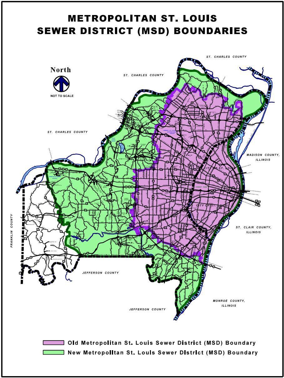
1.3.1 Area Within Metropolitan St. Louis Sewer District (MSD) Boundary - The procedures and responsibilities of review, permit issuance, inspection, fees, and escrows within the original and annexed Metropolitan St. Louis Sewer District (MSD) boundary (see Figure 1 3-1) are as follows:
Permitting Agency Responsibilities Page | 1-4 9/25/2023 Design Criteria Manual
1) MSD Responsibilities
a) Review and approve plans for sanitary sewers, storm sewers, improved channels, detention basins and sinkholes.
b) Review and approve flood plain studies in areas that include structures connected to sanitary sewers in accordance with St. Louis County, Federal Emergency Management Agency (FEMA) criteria and MSD criteria.
c) Issue permits, after plan approval, for sanitary sewers, storm sewers, improved channels and detention basins.
d) Establish an escrow for proposed sanitary sewers, storm sewers, improved channels and detention basins. The escrows are to be released upon completion of MSD requirements.
e) Collect inspection fees based on MSD's present ordinances.
f) Inspect installation of sanitary sewers and storm sewers to a point approximately one foot above the pipe. Inspect improved channels and detention basins.
g) Maintain all public sanitary sewers, public storm sewers and improved channels.
h) Review proposed treatment or utilization of sinkholes on sites.
2) St. Louis County Responsibilities
a) Review and approve land disturbance plans.
b) Review and approve public storm sewers as they affect the public road right-ofway.
c) Review, approve and inspect private storm sewers. This will include off site systems draining to the right-of-way to assure proper size, hydraulic grade lines, backyard drainage which may result in exceeding our criteria of 1 c f s draining between houses and over public sidewalks.
d) Review and approve flood plain studies in accordance with St. Louis County and FEMA criteria.
e) Establish and administer Special Escrows to guarantee improvements, including storm sewers, within right-of-way on municipal projects Notify the Department of Planning regarding release of subdivision escrows upon completion of construction for subdivision developments within unincorporated County.
f) Authorize work through issuance of a Special Use Permit for storm sewers within the public road right-of-way or through land disturbance permit approvals for
Permitting Agency Responsibilities Page | 1-5 9/25/2023 Design Criteria Manual
private storm sewers included with development outside of right-of-way and in unincorporated County
g) Collect fees for inspection of the storm sewers and land disturbance work for development outside of right-of-way in unincorporated County.
h) Inspect storm sewer, sanitary sewer, and sewer lateral backfill from a point one foot above the pipe to the surface in all areas within existing or future public road right-of-way.
i) Maintains the following within the public road right-of-way:
• Bridges;
• Crossroad culverts;
• Driveway culverts;
• Roadside ditches;
• Grated troughs (construction of new grated troughs is not allowed);
• County approved non-standard storm facilities and pipe runs to the first approved MSD structure downstream.
• Provide emergency maintenance on systems within MSD jurisdiction when conditions threaten the safety of the public. Repairs may be of a temporary or permanent nature.
1.3.2 Area Outside Metropolitan St. Louis Sewer District (MSD) Boundary - The procedures and responsibilities of review, permit issuance, inspection, fees, and escrows outside the original and annexed Metropolitan St. Louis Sewer District (MSD) boundary (see Figure 1.3-1) are as follows:
1) MSD Responsibilities
a) MSD has no responsibility for sanitary sewers and storm sewers or detention basins. However, if this area is annexed by MSD, all requirements of Section 1.3.1 will apply.
2) St. Louis County Responsibilities
a) Review and approve land disturbance plans.
b) Review and approve public and private storm sewers, improved channels and detention basins. This will include off site systems draining to the right-of-way to assure proper size, hydraulic grade lines, backyard drainage which may result in exceeding our criteria of 1 c.f.s. draining between houses and over public sidewalks.
c) Review and approve flood plain studies in accordance with St. Louis County and Federal Emergency Management Agency (FEMA) criteria.
Permitting Agency Responsibilities Page | 1-6 9/25/2023 Design Criteria Manual
d) Establish an escrow through the Department of Planning for storm sewers, improved channels and detention basins. Notify the Department of Planning regarding release of escrows upon completion of construction.
e) Issue permits through issuance of Special Use Permit (SUP) for work within County right-of-way and through land disturbance permits for proposed storm sewers, grading, improved channels and detention basins outside of County right-of-way and within unincorporated St. Louis County
f) Collect fees for inspection of storm sewers, grading, improved channels and detention basins as they affect the public road right-of-way per St. Louis County Ordinance.
g) Inspect storm sewers.
h) Maintain the following storm structures within the public road right-of-way: storm sewers, bridges, crossroad culverts, driveway culverts, roadside ditches, existing grated troughs, and non-standard storm structures. Maintain public storm sewers on private property from the public road right-of-way to the first storm structure downstream from the right-of-way.
Permitting Agency Responsibilities Page | 1-7 9/25/2023 Design Criteria Manual
Permitting Agency Responsibilities Page | 1-8 9/25/2023 Design Criteria Manual
Figure 1.3-1 MSD Boundary Map
Chapter 2 Special Use Permits - Work Not Requiring Sealed Drawings
2.0 Applicable Activities - Permitting requirements for activities which do not require sealed drawings are contained within this chapter. Said activities include, but are not limited to, the following categories of work:
1) Utility operations;
2) Municipal operations;
3) Service connections;
4) Departmental Design Contract Work;
a) Subsurface Investigations;
b) Phase 2 Investigation;
c) Other Similar Activities
5) Movement of over-dimension and/or overweight vehicles;
6) Earth hauling;
7) Temporary entrance for earth hauling;
8) Road closures;
9) Tree removal;
10) Residential driveway approaches;
11) Landscaping, and ornamental entrances and signs outside the sight distance boundary;
12) Banners;
13) Traffic Counts
The specific application requirements and conditions for each of these different areas are developed within this chapter
2.1 General Requirements - No person, firm or corporation shall develop, alter or modify any tract of land or roadway within unincorporated St. Louis County or any roadway designated as an Arterial Road (ARS) within any St. Louis County municipality without first securing the approval of the improvements plans as required by the Department, nor shall any person, firm or corporation undertake such work or cause the same to be undertaken without first obtaining the required permits from the Agency having jurisdiction over the proposed construction.
2.1.1 Permit Applicant - The applicant shall be the owner or individual or legal entity having the legal right to control the facilities being constructed, installed or improved (i.e. owner, developer, engineer, general contractor or sub-contractor).

Special Use Permits - Work Not Requiring Sealed Drawings Page | 2-1 9/25/2023 Design Criteria Manual
2.1.2 Approvals / Dedications - When applications are received for projects or installations which require other agency’s approval or which require public easement and/or right-of-way dedications, no permits shall be issued until the Department has received evidence of the required outside approvals and until verification of or guarantee of the recording of all public easements and right-of-way dedications has been made.
2.1.3 Application Requirements - Applications shall be submitted by mail, fax or in person on the form provided by the Department and shall describe the location and the nature of the work to be performed. Applications shall not be accepted if they are incomplete or not accompanied by the following:
1) Plans - Four (4) sets of plans shall accompany the application and shall be required for permit issuance. Applicants shall receive one (1) copy of the approved plans with the permit.
2) Deposits, Bonds, Etc. - When required by the Department, the applicant shall accompany the permit application with the required deposit, bond, insurance, affidavits, and / or other items necessary for that type permit.
a) Insurance Requirements - Any entity that performs work on St. Louis County maintained property shall provide the County with a Certificate of Insurance evidencing general liability coverage (bodily injury and property damage) in the amounts specified as thelimits of liability set by the State for public entities. Such certificate shall include "St. Louis County" as additional insured and shall be provided prior to the issuance of any permit. Certificate shall provide for a 30day policy cancellation notice to St. Louis County. Upon request, the County will provide the specific amounts for both per person and per occurrence limits. The insurance requirements shall not apply to the installation of residential driveways.
2 1.4 Permit Fees - In Section 1105.060, St. Louis County Revised Ordinances (SLCRO), 1974, as amended, the County Council has established permit and inspection fees as follows:
1) Special Use Permit fee (other than utilities) $208.00 per unit Special Use Permit fees (utilities):
a) Point permits in pavement or directional bore with opening in pavement..................... $300.00 per each excavation
b) Linear permits in pavement trench $300.00 per each plus $2.90 per lineal foot
c) Point permits in grass or directional bore bore with opening in grass............................ $190.00 per each excavation
d) Linear permits in grass trench $190.00 per each plus $1.00 per lineal foot
Special Use Permits - Work Not Requiring Sealed Drawings Page | 2-2 9/25/2023 Design Criteria Manual
2) Checks for permit fees shall be made payable to: "Treasurer, St. Louis County".
3) Permit fees shall be based on a unit cost system. Units applicable to new construction shall consist of the following: sanitary sewers and utility facilities in increments of three hundred (300) lineal feet. Driveway entrances, temporary driveway entrances, and utility service connections installed individually shall be considered one (1) unit each.
4) When water mains, gas mains, trunk or lateral sewers, or telephone or power conduits are to be installed continuously for a distance within the public right-of-way, permit fees shall be based on one (1) unit for each continuous three hundred (300) feet of trench length of main, sewer or conduit or portion thereof.
5) When individual connections to water mains, gas mains, trunk or lateral sewers, or telephone or power conduits are installed concurrently with such mains, sewers or conduits, the trench lengths of the individual connections located within the public right-of-way shall be totaled and added to the trench length of the continuous mains, sewers or conduits. Permit fees shall be based on the aggregate trench length of main, sewer or conduits including the portion of attendant connections located within the public right-of-way.
6) When telephone or power poles are to be installed continuously, not necessarily consecutively, within the public right-of-way, permit fees shall be based on one (1) unit for each four (4) poles or portion thereof. When fire hydrants are to be installed within the public right-of-way, permit fees shall be based on one (1) unit for each three (3) hydrants or portion thereof.
7) A permit shall be required for the transportation of any over-dimension and/or overweight vehicle. The permit fee shall be based on one (1) unit for each individual over-dimension and/or overweight move. However, over-dimension and/or overweight permits for vehicles regularly used by utilities to transport poles, mains, conduits, etc. shall be obtained annually at the rate of one (1) unit per vehicle or trailer per month.
8) A permit shall be required for performing traffic counts. The permit fee for nondestructive type traffic counts shall be based on one (1) $208 unit for each project. A project may include multiple counter locations. For destructive type counter requests that include boring into pavement or other physical changes in right-of-way will be addressed on an individual basis.
2 1.5 Permit Extensions - Work authorized by permit shall be expected to be executed without delay within thirty (30) days from date of issuance unless otherwise specified on the permit. Requests for extension of time shall be submitted in writing and shall be reviewed by the Department on an individual basis. Written requests shall include the permit number, map location, date of issuance, project name, street location, reason for requesting extension and number of days required to complete the work.
Special Use Permits - Work Not Requiring Sealed Drawings Page | 2-3 9/25/2023 Design Criteria Manual
2.1.6 Acceptance of Work - Completed improvements within the public road right-of-way shall not be opened to traffic without permission from the Director. Applicants requiring formal or written acceptance by the Department of completed work covered by permit shall submit their request in writing to the Director. Permit number, map location, date of issuance, project name and street location shall be included in all correspondence sent to the Department. Inspectors are to update the computer permit program as an inspection is made.
2.1.7 Enforcement - (Chapter 1105.090, Title XI SLCRO 1974 as Amended)
1) Inspection - Any authorized representative of the Director shall have full access to all portions of any right-of-way work for the purpose of making any investigations to ascertain whether the provisions of this chapter and Chapter 229 RSMo are being complied with, and shall make a timely report to the Director of any violation thereof. It shall be unlawful for any person to interfere with the making of inspections as provided for by this section.
2) Stop Work Orders and Corrective Orders - If upon inspection by the Director or his duly authorized representative, work is proceeding contrary to the provisions of this chapter or Chapter 229 RSMo or in an unsafe manner, the Director may issue stop work orders and corrective orders. Such orders:
a) May be delivered personally or by certified mail to the responsible person designated in the permit application or the person in charge of the construction site at the time of delivery.
b) Shall state that work is proceeding contrary to the provisions of this Chapter or Chapter 229 RSMo or in an unsafe manner, summarize the unauthorized work and provide a period of no longer than thirty (30) days to cure the problem, which cure period may be immediate if necessary to protect the public safety. Any stop work order shall state the conditions under which work may resume.
(Section 1.8 from St. Louis County Ordinance No. 20,610, Approved 9/5/2001)
c) May be appealed to County Council, provided that an application for review is filed with the County Clerk no later than ten (10) days of such order. County Council shall fix a time and a place for a hearing to be held within a reasonable time. Pending the filing and final disposition of an appeal, the Director may stay the enforcement of the order. Such stay may be conditioned upon such terms as shall appear to the Director to be proper. Any decision by County Council denying the appeal shall be in writing and supported by written findings establishing the reasonableness of the decision.
d) May be enforced by equitable action in the Circuit Court of St. Louis County, Missouri, and in such case the person involved in the work shall be liable for all costs and expenses incurred by St. Louis County in enforcing such orders, including reasonable attorney's fees in addition to any and all penalties established in this Chapter.
Special Use Permits - Work Not Requiring Sealed Drawings Page | 2-4 9/25/2023 Design Criteria Manual
3) Unlawful Continuance of Work - No person shall continue any work in violation of a stop work order except such work that is directed to be performed to abate a violation or unsafe condition.
2.1.8 Emergency Work - An emergency is an unforeseen combination of circumstances or the resulting state that calls for immediate action to protect the health, safety and welfare of the general public. When emergencies result in a physical disturbance of the public right-ofway, immediate notification followed by permit application shall be required. When emergencies result in only an interruption of traffic, immediate notification shall be required.
1) Immediate Notification - All emergency work situations shall be reported immediately by telephone to the Department. Emergency work occurring within normal working hours (7:30 am to 4:00 pm Monday-Friday) shall be reported to the Department's Permit Inspection Section at (314) 615-1166. Emergency work occurring at other hours or on Saturdays, Sundays and holidays shall be reported to the St. Louis County Police Information Center at (314) 889-2341. The Department will dispatch its personnel as required by the emergency situation.
2) Permit Application - All parties performing emergency work which results in a physical disturbance of the public right-of-way shall follow up their phone notification with a permit application within twenty-four (24) hours or on the next workday. Plans, sketches or correspondence relating to the permit application shall indicate the complete locational data (i.e. location in driving lane, distance to curb, shoulder, driveway, street intersection, pavement type, etc.) and the particulars of the emergency. In other respects, the requirements of the regular application shall apply.
2.1.9 Permit Offices - Applications for permits shall be submitted in accordance with the following:
1) The starting point for all permit applications for development projects in unincorporated St. Louis County and in those municipalities which have contracted with St. Louis County for building code administration, land disturbance, and drainage review will be the Permit Application Center (PAC). The PAC is located at:
• St. Louis County Department of Transportation & Public Works County Administration Building 41 South Central Avenue - 6th Floor Clayton, Missouri, 63105
Telephone No.: (314) 615-4269
All inquiries concerning permits should be made at this office.
Special Use Permits - Work Not Requiring Sealed Drawings Page | 2-5 9/25/2023 Design Criteria Manual
2) Special Use Permit Office - All applications, fees, plans, correspondence and related information shall be submitted directly to:
• St. Louis County Department of Transportation & Public Works
41 South Central Avenue - 6th Floor
Clayton, Missouri 63105
Attention: Special Use Permit Section
Telephone No.: (314) 615-8517
(7:30a.m. to 4:00p.m., Monday – Friday)
Fax No.: (314) 615-7084
At other hours or on Saturday, Sundays and holidays, all telephone communication shall be directed to the St. Louis County Police Department Information Center at (314) 889-2341.
3) Site Plan Review Office - Commercial and residential site plans, correspondence and related information shall be submitted directly to:
• St. Louis County Department of Transportation & Public Works
41 South Central Avenue - 6th Floor
Clayton, Missouri 63105
Attention: Plan Review Section
Telephone No.: (314) 615-8517
4) Utility Relocations - When utility relocations are required to accomplish the construction proposed within the public right-of-way, the applicant shall coordinate his activities with the utility forces performing the work. All correspondence, plans and other information relating to the relocations shall be submitted directly to:
• St. Louis County Department of Transportation & Public Works
41 South Central - 6th Floor
Clayton, Missouri 63105
Attention: Utilities Coordinator
Telephone No.: (314) 615-8517
Fax No.: (314) 615-7084
Permit taken out for utility work shall name the utility company responsible for the work as the applicant, and the company performing the work as the contractor.
Special Use Permits - Work Not Requiring Sealed Drawings Page | 2-6 9/25/2023 Design Criteria Manual
2.1.10 Other Permits - Permits or approval may be required from one or more of the following agencies:
• St. Louis County Department of Transportation & Public Works County Government Center 41 South Central Avenue - 6th Floor
Clayton, Missouri 63105
Division of Code Enforcement
Telephone: (314) 615-7150
Plan Review
Telephone: (314) 615-5485
• Metropolitan St. Louis Sewer District (MSD) 2350 Market Street
St. Louis, Missouri 63103-2555
Telephone: (314) 768-6200
• Missouri Department of Transportation (MoDOT) 1590 Woodlake Drive
Chesterfield, Missouri 63017
Telephone: (314) 340-4100
• Municipalities
• Private Sewer Companies
2 1.11 Additional Permit Information - Refer to the "Special Use Permit Website" and "Special Use Permit Application" available on the St. Louis County's website
2.2 Municipal Operations - The operations of municipalities and/or their contractors within the public right-of-way shall be subject to the following specific application requirements and conditions. Municipal utilities shall be subject to the requirements of this manual when working within St. Louis County right-of-way
2.2.1 Municipal-County Coordination - When developments within municipalities are located along County roads, the permit for work within St. Louis County right-of-way may be withheld pending receipt of municipal approval. This approval shall be in the form of an approved site plan, correspondence, or a building permit.
Municipal approval of improvement plans does not relieve the developer of meeting all requirements for work performed within St. Louis County right-of-way. Municipalities are encouraged to verify that the Department's requirements for right-of-way dedication, improvements, and other criteria have been fulfilled prior to issuance of its building permit. In all cases, the developer shall be responsible for fulfilling the Department's requirements. The Department shall determine these requirements based on considerations particular to each development.
Special Use Permits - Work
Sealed Drawings
| 2-7 9/25/2023 Design Criteria Manual
Not Requiring
Page
2.2.2 Work Requiring Permit Authorization - All municipal activities which require disturbance of St. Louis County right-of-way or impact traffic on County roadways, as detailed in Chapters 2 and 3 of this manual, shall require permit authorization and shall be subject to the specific requirements of their individual section of this manual.
2.2.3 Work Requiring Notification - All work which results in an interruption of traffic but is not included in the work requiring permit authorization shall be reported by telephone to the Department one (1) workday prior to its implementation. No permit shall be required. Example of this type of work shall include, but not be limited to, the following:
1) Banners
2) Tree trimming
3) Placement of seasonal decorations
Work occurring within normal working hours (7:30 am to 4:00 pm) shall be reported to the Department's Permit Inspection Section at (314) 615-1166. Work occurring at other hours or on Saturdays, Sundays or holidays shall be reported to the St. Louis County Police Department's Information Center at (314) 889-2341.
No work that interrupts traffic shall be permitted on any arterial road during the peak traffic periods (generally 7:00 am to 9:00 am and 3:30 pm to 6:00 pm) with the exception of emergency operations.
2.2.4 Other Work - Work that does not result in a physical disturbance of the public right-ofway and does not interrupt traffic shall not require permit authorization or telephone notification.
2.2.5 Plan Requirements - New municipal construction or street projects shall require submission of improvement plans developed in accordance with the requirements in chapter 3 of this manual. Other municipal operations shall not require plans for permit issuance unless specifically requested by the Department.
2.2.6 Permit Fees for Municipalities - Permit fees using the unit cost system explained in section 2.1.4 shall be charged for:
1) Any construction (or related) work performed by municipal personnel in County rightof-way
2) Any construction (or related) work performed by private contractors for a municipality in County right-of-way.
Such work includes, but is not limited to, irrigation system installation and maintenance, pavement removal and replacement, or any other activity that requires County inspection of an improvement. Permit fees will be waived for permits issued for the installation or maintenance of approved grasses, flowers, shrubs or trees.
Special Use Permits - Work Not Requiring Sealed Drawings Page | 2-8 9/25/2023 Design Criteria Manual
2.2.7 Landscaped Median and Green Space Improvements - The municipality or the landscape design professional (Landscape Architect) hired by the municipality for the proposed project, shall submit plans to this Department for review regarding any proposed improvements, irrigation, landscaped median, green space improvements and plantings that are located within the St. Louis County maintained right-of-way. The municipality or Landscape Architect shall secure all necessary plan approvals, required landscape maintenance agreements and permits from this Department and any other required parties, for the proposed improvements to be located within the St. Louis County maintained right-ofway, before starting any construction.
2.3 General Permit Conditions
2.3.1 Road Crossings - All work authorized by permit shall be inspected for strict compliance with the following conditions. When installations require placement of the cable, conduit or pipe beneath the pavement surfacing, the plans shall indicate the method of installation in accordance with the following:
1) Boring - Crossings of classified roads that have a current year traffic volume of 5,000 average daily traffic or more shall be bored. Casing and other boring requirements, unless supported by subsurface investigation data, shall be decided by the Department during construction. Exceptions to the boring requirement shall be considered by the Department on an individual basis if proper justification such as documented evidence of rock, insufficient cover, etc. is provided.
2) Open Trench - Crossings of roads that have a current year traffic volume of less than 5,000 average daily traffic shall normally be permitted by open trench. However, road closings caused by open trench construction shall not be permitted without prior approval by the Director (refer to Section 2.4.6 road closure). When road closings are not authorized, two (2) lanes of traffic shall be maintained on four (4) lane roads and one (1) lane of traffic on two (2) lane roads. The road shall be restored to normal traffic flow after working hours unless other provisions are authorized.
a) Concrete Pavement - Open trenching of concrete pavement will normally require replacement of the entire slab from joint to joint for the depth corresponding the classification of the pavement or depth of adjacent pavement, whichever is greater. The permit applicant shall be responsible for the repair of any settlement or other failure of the slab for a period of twelve (12) months from the completion of construction. Exceptions to the full slab replacement requirements shall be considered by the Department on an individual basis during permit processing. For material, construction and compressive strength requirements, refer to the "Standard Specifications for Road and Bridge Construction".
Special Use Permits - Work Not Requiring Sealed Drawings Page | 2-9 9/25/2023 Design Criteria Manual
b) Asphalt Pavement - Open trenching of asphalt pavement shall require a saw cut edge and replacement with compacted full depth hot mix asphalt: 2 inches Type "C" and a depth of Type "X" Bituminous pavement or Portland cement concrete for the remaining thickness corresponding the classification of the pavement or depth of adjacent pavement, whichever is greater. The contractor shall mill and overlay the full width of the impacted lane(s) or shoulder(s) for trench excavations that exceed 50 feet longitudinally. When 5 feet or less of pavement remains between the excavation and the nearest joint or pavement edge, the contractor shall mill and overlay to the joint or pavement edge. The permit applicant shall be responsible for the repair of settlement or other failure of the patch for a period of twelve (12) months from the completion of construction. For material, construction and compaction requirements refer to the "Standard Specifications for Road and Bridge Construction" .
c) Driveway and Sidewalk Crossings - Open trenching of existing driveway and/or sidewalk surfaces shall require replacement with full depth material to the existing joints for concrete surfaces or to a saw cut edge for asphalt pavement.
d) Granular Backfill - Open trenching of the existing roadway pavement shall require compacted granular backfill and a temporary asphaltic concrete wearing surface overnight. Open trenching parallel with the edge of the roadway pavement shall require granular backfill when the edge of the proposed conduit, duct, main or pipe trench is less than three (3) feet from the edge of the pavement. For material, construction and compaction requirements refer to the "Standard Specifications for Road and Bridge Construction" .
e) Flowable Fill - Open trenching of existing roadway pavement for MSD and/or utility installations may use flowable fill Where used for trenching operations, the flowable fill shall be used for the full depth of excavation.
Flowable fill shall be used for the construction of all structures; manholes, inlet structures, utility vaults, etc.; where the excavation limits for the installation of said structure will ultimately be under pavement or sidewalk.
For material, construction and compressive strength requirements, refer to the "Standard Specifications for Road and Bridge Construction" .
f) Structures in Pavement - All structures or appurtenances thereof approved for location within or under the roadway pavement shall meet the highway live loading requirements of this Manual. For material and construction requirements, refer to the "Standard Specifications for Road and Bridge Construction".
Special Use Permits - Work Not Requiring Sealed Drawings Page | 2-10 9/25/2023 Design Criteria Manual
g) Traffic Control and Safety Devices - Utilities and contractors shall be required to provide and maintain barricades, nighttime lighting, flashers, cones, flagmen, etc. on the job site as approved by the Department. When detours have been approved for specific installations, the applicant shall provide and maintain the route signing. For material and construction requirements, refer to the "Standard Specifications for Road and Bridge Construction".
h) Peak Hour Traffic - No work other than emergencies reported to the Department under the procedure of Section 2.1.8 of this manual shall be permitted on arterial roads during peak traffic periods. The Department shall determine the extent of the peak traffic period for each particular roadway.
2.3.2 Temporary Openings - All work authorized by permit shall be inspected for compliance with the following conditions. Temporary openings in the road pavement shall be limited in size to a rectangular opening not to exceed three (3) feet by four (4) feet, unless special permission is granted by the Department for larger openings. The thickness of the pavement replacement material for temporary openings shall depend upon the classification of the street involved.
1) Granular Backfill - All pavement excavations, except those for which plate use has been authorized, shall require compacted granular backfill and a temporary asphaltic concrete wearing surface overnight. For material and construction requirements, refer to the "Standard Specifications for Road and Bridge Construction".
2) Plates - The use of steel plates within the public road right-of-way shall be strictly governed by the Department. Only steel plates conforming to the designs previously approved by the Department shall be used. Other designs must be submitted for review and approval prior to their use under these conditions. For material and construction requirements, refer to the "Standard Specifications for Road and Bridge Construction" (Section 626 - Temporary Steel Plate Trench Bridging) and St. Louis County Standard Drawing C613.05"Temporary Steel Plate Trench Bridging".
2.4 Specific Requirements
2.4.1 Utility Operations - The operations of utility companies and / or their sub-contractors within the public right-of-way shall be subject to the following specific application requirements and conditions:
1) Work Requiring Permit Authorization - All work which results in a physical disturbance of the public right-of-way shall require permit authorization. This requirement shall include, but not be limited to, all excavations, street crossings, and installations relating to conduit, poles, pole lines, wires, antennas, antenna support structures, mains, pipes, valves, conductors, sewers, drains or appurtenances thereof. Emergency work which results in a physical disturbance of the public right-of-way shall require immediate notification of the proposed work by telephone followed by permit application. Emergency over-dimension and / or overweight movement shall require immediate notification of the proposed move by telephone followed by application. Refer to Section 2.1.8 for the complete emergency procedure. This may be waived in
Special Use Permits - Work Not Requiring Sealed Drawings Page | 2-11 9/25/2023 Design Criteria Manual
major storm or disaster situations involving multiple facility damage. However, normal restoration of the public right-of-way shall be made after the emergency repairs are complete.
2) Work Requiring Notification - All work which results in an interruption of traffic but does not involve a physical disturbance of the public right-of-way shall be reported by telephone to the Department one (1) workday prior to its implementation. No permit shall be required. Examples of this type of work shall include, but not be limited to:
a) The opening and/or inspection of manholes, vaults, and other structures located within the pavement surface;
b) The inspection and splicing of aerial cable and wire;
c) The installation of new cable within existing facilities;
d) Other similar activities
Work occurring within normal working hours (7:30 am to 4:00 pm) shall be reported to the Department's Permit Inspection Section at (314) 615-1166. Work occurring at other hours or on Saturdays, Sundays and holidays shall be reported to the St. Louis County Police Department's Dispatcher at (314) 889-2341.
No work which interrupts traffic shall be permitted on any arterial road during the peak traffic period (generally 7:00 am to 9:00 am and 3:30 pm to 6:00 pm) with the exception of emergency operations.
Emergency work which results in an interruption of traffic but does not involve a physical disturbance of the public right-of-way shall require immediate notification of the proposed work by telephone to the appropriate number listed above. Refer to Section 2.1.8 for the complete emergency procedure. This emergency procedure may be waived in major storm or disaster situations involving multiple facility damage.
Emergency work of this type shall not require permit authorization or telephone notification.
3) Bonds - All utilities shall deposit with the Department a blanket corporate or surety bond in the amount of $50,000 to cover possible damages to the roadway, traffic control, devices, structures, culverts or other facilities present in the public right-of-way occurring as a result of their operations.
4) Insurance Requirements - Any entity that performs work on St. Louis County maintained property shall provide the County witha Certificate of Insurance evidencing general liability coverage (bodily injury and property damage) in the amounts specified as the limits of liability set by the State for public entities. Such certificate shall include "St. Louis County" as an additional insured and shall be provided prior to the issuance of any permit. Certificate shall provide for a 30-day policy cancellation notice to St. Louis County. Upon request, the County will provide the specific amounts for both per person and per occurrence limits.
Special Use Permits - Work Not Requiring Sealed Drawings Page | 2-12 9/25/2023 Design Criteria Manual
5) Application Requirements - Applications shall be submitted on the form provided by the Department. Utility applicants may add to the application form additional data considered necessary for project identification and/or company coordination.
a) Routine - Routine applications shall be submitted in accordance with the requirements of Section 2 1.3 of this manual
b) Emergency - Emergency applications shall be submitted in accordance with the requirements of Section 2.1.8 of this manual
c) Subcontractor - Applicant must list subcontractor performing the work on the permit application. All contractors and subcontractors shall be subject to the insurance requirements stated in Section 2.4.1.4.
6) Plan Requirements - All utility installations shall be depicted in accordance with the requirements and exhibits of this manual. The extent of the plans required for permit issuance for the proposed installation shall be determined by the Department based on the street classification and the scope of the work proposed.
a) Arterial Roads - Plans for installation to be located within the public right-of-way of arterial roads shall be developed as follows:
i) Section View - Show the location of the proposed installation dimensioned relative to the existing roadway conditions and the ultimate typical section. Indicate the relationship between the existing pavement, shoulders, ditches, embankments, terraces, etc. and the future roadway improvements.
ii) Plan View - Show the proposed installation and all existing roadway conditions within the public right-of-way or easements, including the pavement surface, the right-of-way line, driveways, sidewalks, culverts, storm and sanitary sewers and other utilities. Indicate the method of installation for all pavement crossings.
iii) Profile View - Indicate the involvement of the proposed installation with any existing sewers or structures as required.
b) Non-Arterial Roads - The location of proposed installations within the public right-of-way of non-arterial or minor streets shall be depicted on minimal plans which clarify the relationship between the new installation and the existing improvements within the right-of-way unless otherwise required.
7) Permit Fees - The unit cost system for permit fees is explained in Section 2 1.4. However, the permit fees for utility installations shall be waived in certain special cases. These exceptions shall be as follows:
a) No permit fee shall be charged for utility relocations required as part of public road improvements constructed by or for the County.
Special Use Permits - Work Not Requiring Sealed Drawings Page | 2-13 9/25/2023 Design Criteria Manual
b) No permit fee shall be charged for utility installation within a new subdivision development on streets that have not been accepted for St. Louis County maintenance and are covered under a valid Land Subdivision Bond or Escrow Agreement as required by the "St. Louis County Subdivision Ordinance" (Section 1005.080).
8) Billing Arrangements - To provide faster handling of utility applications and fees, the Department has established a special billing arrangement available to all utilities operating within the public road right-of-way. Utility applicants requesting permit handling under this procedure shall submit theirrequest tothe Department for approval and implementation.
a) Initial Deposit - The amount of the initial deposit shall be based on the average monthly permit fee requirements in $1,000 units.
b) Daily-Weekly Prepaid Listings - Each permit application approved for permit issuance shall be added to the listing prepared by the Department. After the permits issued have been tabulated on the listing, the total amount of each listing shall be deducted from the initial deposit amount or balance thereof and forwarded to the applicant utility for reimbursement.
c) Reimbursement Payments - Checks covering the total amount of each listing shall be prepared by the applicant and forwarded promptly to the Department to maintain the initial deposit amount.
d) Insufficient Funds - Permits shall not be issued when insufficient funds remain from the initial deposit to cover the permit fee.
e) Account Status - Utility applicants may request periodic status reports of the permit fee account for accounting purposed. Such requests shall be made on a form approved by the Department and shall not exceed one (1) per month.
9) Supplemental Permit Conditions
a) ADA Compliance - All permanent improvements shall be fully ADA compliant. Pedestrian access shall be maintained at all times during project construction Where the existing pedestrian route must be closed for construction activities, an alternative pedestrian route which minimizes pedestrian inconvenience shall be provided. The applicant shall minimize closures of the pedestrian access route to the maximum extent practicable. Where the existing pedestrian access route must be repaired or replaced, restoration of said route shall commence immediately upon completion of utility work.
b) Roadside Design Compliance - All above ground utility appurtenances shall comply with the requirements of Section 5.11 Roadside Design Requirements
Special Use Permits - Work Not Requiring Sealed Drawings Page | 2-14 9/25/2023 Design Criteria Manual
c) Utility Poles and Commercial Antennas - Prior to the issuance of any permit for installation of a pole or antenna support structure in the St. Louis County rightof-way or easement, the applicant shall submit a notarized statement agreeing to make the proposed pole or structure available for use by others, subject to reasonable technical limitations and financial terms.
Prior to the issuance of any permit for a pole or antenna support structure, the applicant shall demonstrate why co-use of nearby facilities is inappropriate or is otherwise not permitted.
Prior to the issuance of any permit for an antenna, the applicant shall furnish an inventory of all known antenna support structures or sites located in or within one-half (½) mile of the proposed new structure that could be used for the applicant's antenna attachment. The inventory shall identify the owner, type and reference name or number and the street location, latitude and longitude, height, type and mounting height of existing antennas and an assessment of available space for the placement of additional antennas, shelters and/or cabinets. The applicant shall further demonstrate why co-use on the identified facilities are inappropriate or is otherwise not allowed.
St. Louis County Department of Transportation & Public Works shall consider the evidence submitted with the Antenna or Pole permit application as well as additional information presented by the applicant. Before approving a permit for a commercial antenna or pole, the Department shall consider and determine the following, as may be applicable, based on the evidence submitted:
i) Whether existing antenna support structures or poles located within the geographic area necessary to meet the applicant's engineering requirements.
ii) Whether existing antenna support structures or poles are within the applicant's required geographic area are of sufficient height to meet system engineering requirements.
iii) Whether existing antenna support structures or poles have sufficient structural strength to support the applicant's proposed commercial antenna or other commercial use.
iv) Whether the proposed commercial antenna would experience or cause signal interference with other telecommunication facilities.
v) Whether the fees, costs or other contractual terms required by the owners of existing antenna support structures or poles within the required geographic area of the applicant, and/or the cost to retrofit the existing structures, are reasonable.
Special Use Permits - Work Not Requiring Sealed Drawings Page | 2-15 9/25/2023 Design Criteria Manual
vi) Whether or not there are other limiting conditions that render existing antenna support structures or poles within the applicant's required geographic area unsuitable.
vii) Whether the design of the commercial antenna, antenna support structure, or pole maximally reduces visual degradation of neighboring properties.
viii) Whether the design of the commercial antenna, antenna support structure, or pole maximally reduces visual degradation of the skyline.
ix) Whether the proposed commercial antenna, antenna support structure, or pole minimizes the number and size of similar facilities that will be required in the geographic area surrounding the proposed site.
2.4.2 Departmental Design Contracts - The work of consultants/contractors and/or their subcontractors within the public right-of-way shall be subject to the following specific application requirements and conditions. Utility work shall be subject to the requirements of Section 2.4.1 of this manual.
1) Work Requiring Permit Authorization - All work which results in a physical disturbance of the public right-of-way shall require permit authorization. Examples of this type of work include geotechnical exploration and Phase II explorations involving excavation or core drilling.
2) Work Requiring Notification - All work which results in an interruption of traffic but is not included in the work requiring permit authorization shall be reported by telephone to the Department one (1) workday prior to its implementation. No permit shall be required. An example of this type of work is surveying.
Work occurring within normal working hours (7:30 am to 4:00 pm) shall be reported to the Department's Permit Inspection Section at (314) 615-1166. Work occurring at other hours or on Saturdays, Sundays or holidays shall be reported to the St. Louis County Police Department's Information Center at (314) 889-2341.
No work that interrupts traffic shall be permitted on any arterial road during the peak traffic periods (generally 7:00 am to 9:00 am and 3:30 pm to 6:00 pm) with the exception of emergency operations.
3) Other Work - Work that does not result in a physical disturbance of the public rightof-way and does not interrupt traffic shall not require permit authorization or telephone notification.
Special Use Permits - Work Not Requiring Sealed Drawings Page | 2-16 9/25/2023 Design Criteria Manual
4) Application Requirements - Applications shall be submitted on the form provided by the Department and shall describe the location and the nature of the work to be performed.
a) Routine - Routine applications shall be submitted in accordance with the requirements of Section 2 1.3 of this manual
b) Emergency - Emergency applications shall be submitted in accordance with the requirements of Section 2.1.8 of this manual.
5) Plan Requirements - Excavations and pavement cuts shall require submission of improvement plans developed in accordance with the requirements of chapter 3 of this manual
6) Permit Fees - Permit fees for Departmental Design Contracts shall be waived.
2.4.3 Service Connections - The installation, repair and/or replacement of water or sewer service connections within the public right-of-way by licensed contractors or companies shall be subject to the following specific application requirements and conditions. Service connection work performed by utilities shall be subject to the specific application requirements and conditions of Section 2.4.1 of this manual
1) Work Requiring Permit Authorization - All work which results in a physical disturbance of the public right-of-way shall require permit authorization. This requirement shall include, but not be limited to, the installation, repair and/or replacement of water service lines, storm and sanitary sewer laterals or appurtenances thereof. Emergency work that results in a physical disturbance of the public right-of-way shall require immediate notification of the proposed work by telephone followed by permit application. Refer to Section 2.1.8 for the complete emergency procedure.
2) Applicant's Responsibility - The applicant shall have at his disposal all personnel, equipment and materials required to perform the proposed work in accordance with the conditions of the permit as issued.
3) Approvals Required for Permit Issuance - All applicants shall provide on the application the plumbing permit number for the proposed work obtained from the St. Louis County Department of Public Works or the municipality in which the work is located. For commercial developments located within the jurisdiction of the Metropolitan St. Louis Sewer District (MSD), permit issuance for sanitary or storm sewer connections may be withheld pending the receipt of MSD approved plans.
Special Use Permits - Work Not Requiring Sealed Drawings Page | 2-17 9/25/2023 Design Criteria Manual
4) Application Requirements - Applications shall be submitted on the form provided by the Department and shall describe the location and the nature of the work to be performed. Note that requests for the use of approved plates shall be accepted only in conjunction with permit application.
a) Routine - Routine applications shall be submitted in accordance with the requirements of Section 2.1.3 of this manual.
b) Emergency - Emergency applications shall be submitted in accordance with the requirements of Section 2.1.8 of this manual
5) Plan Requirements - New Service connection installations for commercial developments shall be shown on the improvement plans for the site developed in accordance with the requirements of Chapter 3 of this manual. The applicant shall provide these plans for use by the Department in the issuance of the service connection permit. New service connection installations for residential developments as well as the repair and/or replacement of existing service connections shall not require plans for permit issuance unless specifically requested by the Department.
6) Deposits and Refunds - All applicants for service connection permits shall have an excavation deposit of $2,000 on account with the "Treasurer, St. Louis County". This excavation deposit shall cover the cost to the County for the repair of substandard work in the public right-of-way. This deposit shall be retained on file for one (1) year following completion of the work authorized by permit. An applicant who will no longer be working within the County right-of-way may receive an excavation deposit refund, after this time period, by submitting the refund request in writing to the Department and enclosing the original excavation deposit receipt.
2.4.4 Movement of Over-Dimension and/or Overweight Vehicles - Permit authorization shall be required for the movements of any vehicle or combination of vehicles and/or loads that exceed the legal dimension and/or weight limits.
1) Legal Dimension and/or Weight Limits - Legal size and weight limits in the County are the same as those required by Missouri State laws, except in cases when the County Council has established roadway load limits by ordinance or when bridges are posted under state regulations. Special load limit roadway data is available for inspection at the Department's Administrative Office.
All size and weight limits listed in this section include the load of the vehicle. All limits that refer to interstates or certain designated highways include roads up to 10 miles from the interstate or highway.
Special Use Permits - Work Not Requiring Sealed Drawings Page | 2-18 9/25/2023 Design Criteria Manual
HEIGHT - Maximum height of any vehicle 15 feet
WIDTH - Maximum width of any vehicle 8½ feet
LENGTH:
a) Maximum length of any single vehicle 45 feet
b) Maximum length of any bus or trackless trolley coach not including one foot in front and back for safety bumper 45 feet
c) Maximum length of truck-tractor and semi-trailer:
i) Upon interstates and certain designated highways, the length of the semi-trailer (no overall maximum length, includes load).........53 feet
ii) Upon all other roads........................................................................60 feet
d) Maximum length of truck-tractor, semi-trailer, and trailer combinations (double bottoms):
i) Upon interstates and certain designated highways, the length of the semi-trailer or trailer (no overall maximum length).......28 feet
ii) Upon all other roads........................................................................65 feet
e) Maximum length of truck and trailer(s) and all other combinations of vehicles:
i) Upon interstates and certain primary highways 65 feet
ii) The overall maximum length upon all other roads 55 feet
f) Maximum length of Automobile Transporters and Boat Transporters:
1) Conventional 5th Wheel 75 feet (for combination unit plus)
2) Stinger-steered 75 feet (3 feet front to 4 feet rear overhang)
g) Maximum length of Drive away Saddle Mount Combinations (Double or Triple on interstate and designated highways) 97 feet
Motor vehicle carriers may carry loads that extend beyond their legal length limits. Loads must not extend more than 3 feet beyond the front or 4 feet beyond the rear of the vehicle.
Special Use Permits - Work
Requiring Sealed Drawings Page | 2-19 9/25/2023 Design
Not
Criteria Manual
EXEMPTIONS FROM SIZE LIMITS - The following exemptions do not include interstate highways:
a) Farm machinery driven occasionally for short distances;
b) Vehicles temporarily transporting farm machinery;
c) Implement dealers delivering or moving farm machinery for repair;
d) Vehicles temporarily transporting road-making machines or road materials;
e) Vehicles towing disabled vehicles for repair on highways.
WEIGHT LIMITATIONS (WITHOUT SPECIAL PERMIT) - A bridge's weight limit may differ from the road’s weight limit. If a bridge has a different weight limit, the limit will be posted.
MAXIMUM WEIGHT ON ANY SINGLE AXLE
a)
b)
c)
a)
b)
ON ANY TANDEM AXLE
GROSS WEIGHT - The actual gross weight allowed depends on the distance from the first to last axle. To determine the maximum gross weight allowed in a commercial zone, multiply the number of axles by 22,400 pounds. 80,000 pounds maximum gross weight is allowed on all highways in Missouri, except where bridge structures are posted with lesser weight limits.
a) Maximum gross weight allowed on interstates, primary and other designated highways ..................................... 80,000 pounds
2) Insurance - Any entity that performs work on St. Louis County maintained property shall provide the County with a Certificate of Insurance evidencing general liability coverage (bodily injury and property damage) in the amounts specified as the limits of liability set by the State for public entities. Such certificate shall include "St. Louis County" as an additional insured and shall be provided prior to the issuance of any permit. Certificate shall provide for a 30-day policy cancellation notice to St. Louis County. Upon request, the County will provide the specific amounts for both per person and per occurrence limits.
Special
- Work
Sealed Drawings Page | 2-20 9/25/2023 Design
Manual
Use Permits
Not Requiring
Criteria
POUNDS
20,000
Maximum weight allowed on interstates
22,400
Maximum weight allowed in a commercial zone
all
22,000 MAXIMUM
POUNDS
Maximum weight allowed on
other routes
WEIGHT
Maximum weight
on interstates 34,000
allowed
Maximum
on all other
36,000
weight allowed
routes
MAXIMUM
3) Application Requirements - Applications shall be submitted in accordance with the requirements of Section 2 1.3 of this manual. In addition, the applicant shall provide the following details of the proposed move:
a) Description of the load itself (height, width, length, approximate weight and method of securing).
b) Description of the moving equipment (license number, height, width, length, number and spacing of axles, number of wheels, maximum pulling and braking power).
c) Certification that the pulling and braking power of the vehicles to be used shall be adequate for all grades to be encountered during the move.
4) Plan Requirements - The applicant shall provide four (4) copies of a map showing the route of the move from the beginning location to the destination for areas in St. Louis County and the approximate amount of time required. In addition, the applicant shall provide the dimensions and approximate weight of load.
5) Scheduling Requirements - Movements during peak traffic hours shall not be permitted. In all cases, the applicant shall comply with the following time schedule for notifying the Department and other Agencies:
a) Allow one (1) working day for review and processing by the Department.
b) It shall be the applicant's responsibility to contact all fire and police departments within municipalities in which the move will take place (including unincorporated area fire and police departments).
c) Contact the Department's Special Use Permit Inspector at (314) 615-1166 prior to the move in order to confirm the time of the move and arrange last minute details.
6) Permit Fees - The applicant shall pay a minimum permit fee of $116 for the overdimension and / or overweight movement. Inspection fees are determined by estimated inspection time and time of day of the move (i.e. beyond normal working hours). The applicant shall provide a refundable deposit of $200 for an over-dimension permit and a $500 refundable deposit for an overweight permit.
Special Use Permits - Work Not Requiring Sealed Drawings Page | 2-21 9/25/2023 Design Criteria Manual
7) Supplemental Permit Conditions - Over-dimension and / or overweight movements shall be subject to following conditions:
a) The permit shall be available for inspection on the vehicle or trailer at all times during the move.
b) The move shall be made under the direct supervision of the Department's Inspector on location.
c) Any and all precautions deemed necessary by the Department shall be taken to prevent damage to any structures or culverts in route, including shoring, plating and/or bridging.
d) Escorts front and rear of the move vehicle equipped with flashing lights and additional safety devices shall be provided as directed by the Department and authorized by the police agency having jurisdiction.
e) An observer in the move vehicle and all the personnel necessary to perform any related work including flagging, shoring, trimming, bracing, etc. shall be provided as directed by the Department.
8) Annual Permits - Approved utility companies may obtain permits on an annual basis authorizing the over-dimension and/or overweight movements of vehicles or trailers regularly used to transport poles, mains, conduits, etc. The following shall apply to these annual permits:
a) The utility shall provide the license plate numbers of all vehicles and/or trailers operating on an annual permit basis. Each vehicle and / or trailer shall be authorized individually by permit. The permit shall remain available on the vehicle at all times.
b) The utility shall agree to take all precautions necessary to prevent damage to any roadway improvements.
c) The insurance or surety bond coverage required for utility movements on an annual permit basis is explained in Section 2.4.1.4 of this manual
2.4.5 Earth Hauling - Applications for Special Use Permits authorizing driveway entrances to provide access to construction sites for grading and earth hauling shall be subject to the following specific application requirements and conditions:
1) Land Disturbance Permit - The applicant shall obtain a permit issued by the St. Louis County Department of Transportation & Public Works or the municipality in which the site or property is located authorizing the grading and hauling of material to or from the site.
Special Use Permits - Work Not Requiring Sealed Drawings Page | 2-22 9/25/2023 Design Criteria Manual
2) Application Requirements - Applications shall be submitted in accordance with the requirements of Section 2 1.3 of this manual. In addition, the applicant shall provide the following details of the proposed work:
a) Cubic yards of material to be hauled.
b) Locations of all entrances required.
3) Plan Requirements - When earth hauling is performed in conjunction with an approved development, the applicant shall provide copies of the site plan showing the temporary provisions required by the hauling operation. For locations not under development, the applicant shall provide copies of a sketch showing the existing roadway improvement within the right-of-way affected by the location of the access. When earth hauling involves multiple sites, all locations to be used shall be identified at the time of permit application. If additional sites are required after permit issuance, the new entrance location shall be authorized by additional permit(s).
4) Permit Fees - The applicant shall pay a permit fee of $208 for each temporary driveway entrance within the County right-of-way required for the earth hauling operation.
5) Supplemental Permit Conditions - Earth hauling authorized by the Department shall be subject to the following conditions:
a) Temporary driveway entrances shall be located as directed by the Department and shall be located as to provide adequate sight distance
b) All temporary surfaces shall be constructed of mechanically compacted eight (8) inch thick type 5 aggregate surface. Material and construction requirements shall follow the St. Louis County "Standard Specifications for Road and Bridge Construction" (Division 300), and the St. Louis County "Sediment and Erosion Control Manual".
c) Applicant shall keep the roadway pavement clean and free of mud, rock and debris at all times during hauling operations. A wash station consisting of a rock area connected to the temporary driveway and a water service line or water truck will normally be required for removal of mud from trucks leaving the site. Other methods of mud control must be submitted to the Department for consideration and approval prior to their use under these conditions.
d) The use of any flagmen required to control traffic shall be determined by the Department at the time of permit issuance.
e) Any limitation of the use of entrances required during rush hour traffic shall be determined by the Department at the time of permit issuance.
Special Use Permits - Work Not Requiring Sealed Drawings Page | 2-23 9/25/2023 Design Criteria Manual
f) Following completion of the hauling operations, all temporary materials shall be removed from the right-of-way. Existing improvements damaged shall be replaced as directed by the Department. Restoration of the disturbed earth areas within the right-of-way shall be completed within thirty (30) days after the closing of the temporary driveway.
2.4.6 Road Closure - The Director has the sole authority to authorize a road closure. The closing of a road shall not be authorized if means are available to perform the proposed construction or maintenance work while keeping the road open to thru traffic. Further, this Department shall not authorize any road closure isolating any building from fire, ambulance, or police protection. If a road must be closed to thru traffic, a permit application shall be submitted to the Department. An additional permit application shall not be required if the authorization request for the road closure is incorporated in the application for construction work. A request for a road closure must be given a minimum of seven (7) working days prior to issuance of a permit in order to give adequate notice to schools, police, fire, etc. A detour map must be submitted for review and approval with the request, along with approvals from any municipality that the closure lies in.
1) Application Requirements - Applications shall be submitted in accordance with the requirements of Section 2.1.3 of this manual. In addition, the applicant shall provide the following details of the proposed road closure:
a) An accurate map showing the exact location of the requested road closure.
b) A proposed detour route for thru traffic shown on the location map.
c) Four (4) complete sets of the construction plans.
d) An explanation of why the closure is required.
e) The proposed closure and reopening dates for the subject road.
2) Permit Fees - The permit fee shall be based on the estimated inspection time and vehicle usage by Department personnel. Refer to Section 2.1.4 of this manual
3) Supplemental Permit Conditions - Upon receipt of the required data, the Department shall review the proposal and, if approved, shall issue the required permit. Road closures authorized by the Department shall be subject to the following conditions:
The Department shall decide the final route. The applicant shall provide the necessary detour signing to be located per Department guidelines.
2.4.7 Residential Entrances - A permit to remove and replace the existing driveway approach is issued at no charge. No charge only if the driveway approach is being reconstructed to the same dimension and in the same location as the one removed. No plan required for this situation.
When driveway construction or widening is proposed within five (5) feet of the abutting property line, a letter indicating the abutting property owner’s knowledge of the work shall be required prior to permit issuance.
Special Use Permits - Work Not Requiring Sealed Drawings Page | 2-24 9/25/2023 Design Criteria Manual
1) Application Requirements - Applications shall be submitted in accordance with the requirements of Section 2.1.3 of this manual.
2) Plans - The applicant shall provide a plan or sketch showing the new driveway location, the culvert location (if required), the details of the driveway widening, sidewalk construction, grading, etc. in accordance with the requirements of the "Design Criteria for the Preparation of Improvement Plans" manual If minimal plans accompany the permit application, the Department recommends that the applicant provide photographs of the existing conditions of the pavement, curbing, shoulder, roadway ditch, sidewalk, etc. to expedite permit issuance When residential development occurs within new subdivisions, the applicant may be required to prepare plans, perform grading and construct sidewalks in accordance with the subdivision plans approved by the County.
3) Permit Fees - The permit fee for driveway construction or widening shall be based on the estimated inspection time and vehicle usage by Department personnel. Refer to Section 1.1.4.2 of this manual.
4) Supplemental Permit Conditions - Driveway construction authorized by the Department shall be subject to the following conditions:
a) Residential entrances on existing County roads shall not be less than ten (10) feet wide at the right-of-way line. When the distance between the sidewalk and pavement edge is less than four (4) feet, the minimum entrance width shall be twelve (12) feet.
b) Residential entrances on existing County roads shall be located so the edges of the curb opening shall be a minimum of five (5) feet from the nearest edge of street inlets and ten (10) feet from the street corner radius point The edges of the curb opening shall not project beyond the side property line extended normal to the pavement Clearances and dimensions are shown on Exhibits 40.35-1 and 40.35-2.
c) In the case of corner lots, no driveways shall be constructed within the corner triangle area bounded by the property lines of a corner lot and a line connecting two (2) points on the property lines each measured thirty (30) feet from the intersection of the two property lines at the intersection Where applicable, easement lines shall be substituted for property lines.
d) The distance between adjacent residential entrances shall be a minimum of twenty (20) feet measured along the road right-of-way line When residential development conditions necessitate reduction of the distance between adjacent residential entrances to ten (10) feet or less, the Department may require a Common Entrance Approach.
Special Use Permits - Work Not Requiring Sealed Drawings Page | 2-25 9/25/2023 Design Criteria Manual
2.4.8 Landscaping, Ornamental Entrance Monuments and Signs - Landscaping, ornamental entrance monuments and signs shall not be placed or constructed within public road right-of-way without authorization by the Department through the issuance of a permit. All landscaping where permitted within St. Louis County Right-of-Way shall follow the requirements in Section 5.19, Landscaping. Applications for permit shall include the following specific information:
1) Plans - Plans shall be submitted showing elevation and section views of the proposed construction. Plans shall indicate the location of the adjacent curbing, sidewalk, street pavement, utilities, and/or landscaping. Corner triangle and sight distance triangle shall be shown on the plans.
2) Agreement or Indentures - When landscaping, entrance monuments or signs involve industrial or residential subdivisions, permits authorizing such items shall be issued only to the Trustees or other individuals designated in the Subdivision Trust Indentures. When the recorded indentures do not provide for these items, amendments shall be recorded prior to permit issuance. For non-subdivision properties, landscaping and sign permits shall be issued only when conditioned by an agreement.
3) Liability and Maintenance - As provided for in the agreement or indenture, the permit applicant shall be responsible for the maintenance and repair of items authorized by the permit. Applicants shall hold the County harmless from all claims, demands and suits of any kind arising out of or in conjunction with any permits issued. Landscaping, entrance monuments or signs located within the public right-of-way under permit authorization shall be removed if requested in writing by the Department.
2.4.9 Banners - Although no permit is required, banners shall not be placed within the public road right-of-way without notification in writing to the St. Louis County Department of Transportation. Applicants shall be responsible for the banner installation, maintenance and removal. Banners shall be located with their lowest point a minimum of sixteen and one-half (16½) feet above the roadway surface. Notification to the Department is not an authorization to use utility poles, light standards or other existing structures located in the road right-of-way. Written notification shall include the following specific information:
1) Message - Indicate the message to be displayed on the banner.
2) Size - Provide the dimensions of the banner.
3) Location - Indicate the proposed location within the public right-of-way, the street name and the distance to the nearest intersection.
4) Duration -Indicate the dates the banner shall be installed and removed from the public right-of-way.
Special Use Permits - Work Not Requiring Sealed Drawings Page | 2-26 9/25/2023 Design Criteria Manual
2.4.10 Miscellaneous - All work which results in a physical disturbance of the public right-ofway or interrupts traffic shall require permit authorization and/or telephone notification. Where the specific scope of work is not covered in this manual the Department shall be contacted prior to the commencement of work. An assessment of the appropriate permit conditions shall be determined on a case by case basis as necessary.
Failure to contact the Department prior to the commencement of work shall result in enforcement actions.
2.5 Glossary
Applicant ........................................
The governmental agency, utility company, contractor, developer or individual seeking permission to work within the right-of-way or any roadway on the Arterial Road System (ARS) or County Road System (CRS).
Arterial Road System (ARS) ..........
The system of roads classified by the Department which provides the principal routes for an interconnected through traffic movement in both the municipalities and unincorporated St. Louis County. Arterial Roads within municipalities are assigned St. Louis County jurisdiction by State law and County ordinance.
Corner Triangle ..............................
The area bounded by the property lines of a corner lot and a line connecting two (2) points on the property lines each measured thirty (30) feet from the intersection of the two (2) property lines at the street intersection (Figure 5.9-3)
County St. Louis County, Missouri
County Road System (CRS)
Department
Director
Emergency
All County maintained roads located in unincorporated St. Louis County, exclusive of roads on the Arterial Road System.
The St. Louis County Department of Transportation & Public Works
The Director of the St. Louis County Department of Transportation & Public Works
An unforeseen combination of circumstances or the resulting state that calls for immediate action to protect the health, safety and welfare of the general public.
Non-Arterial Road
A St. Louis County maintained roadway not designated as an Arterial Road.
Special Use Permits - Work Not Requiring Sealed Drawings Page | 2-27 9/25/2023 Design Criteria Manual
Special Use Permits - Work Not Requiring Sealed Drawings
Permit The Special Use Permit.
Road
Right-of-way
The public way for purposes of travel and access for vehicular and pedestrian traffic located within the public right-of-way. Road shall include all other designations such as highway, street, avenue, roadway, public easement, etc.
The land, generally in a strip, dedicated to or acquired by St. Louis County for public use forever or assigned to St. Louis County jurisdiction by ordinance for the construction and maintenance of public roads.
Sight Distance Triangle ................. Defined by Supplemental Drawing 5.2, Sight Distance at Intersections.
Special Use Permit Fee
(Utilities) .........................................
Permits / projects not requiring plans signed and sealed by a registered professional Engineer or a review by engineering staff.
Special Use Permit Fee
(Development)................................
Permit / projects requiring engineered drawings and plan review by engineering staff.
9/25/2023
Design Criteria Manual
Page | 2-28
Chapter 3 Special Use Permits - Improvements and Developments
3.0 Applicable Activities - A Special Use Permit (SUP) is required to be obtained from St. Louis County prior to the start of any work in County right-of-way.
Permitting requirements for the following activities are contained within this chapter.
3.0.1 Commercial Development - Commercial development is defined as any development of property zoned for commercial use. Any development of commercial property within unincorporated St. Louis County or within a municipality fronting a County road shall be required to meet the permitting requirements of this chapter.
3.0.2 Residential Development - Residential development is defined as any development of property zoned for residential use. Any development of residential property within unincorporated St. Louis County or within a municipality fronting a County road shall be required to meet the permitting requirements of this chapter.
3.0.3 Improvements within St. Louis County Right-of-Way - Improvements shall be defined as any permanent improvement constructed within St. Louis County right-of-way with the exception of those items covered in Chapter 2. The following list contains examples of said improvement types
1) Monuments, Landscaping, and Signs within the Sight Distance Boundary;
2) Metro Bus Facilities;
3) Landscape median enhancements;
4) Entrance work;
5) Road widening;
6) Sidewalk
3.1 General Requirements - No person, firm or corporation shall develop, alter or modify any tract of land or roadway within unincorporated St. Louis County or any roadway designated as an Arterial Road (ARS) within any St. Louis County municipality without first securing the approval of the improvements plans as required by the Department, nor shall any person, firm or corporation undertake such work or cause the same to be undertaken without first obtaining the required permits from the Agency having jurisdiction over the proposed construction.
Plans detailing work within St. Louis County right-of-way arereferred to as either "Concept Plans" or "Improvement Plans" within this chapter.
Plans detailing site development, regardless of jurisdiction, are referred to as "Site Plans" within this chapter. Site plans which detail improvements within St. Louis County right-of-way will be accepted for review as "Improvement Plans" provided they meet the requirements of this manual for the areas shown within right-of-way.
Special Use Permits - Improvements and Developments Page | 3-1 9/25/2023 Design Criteria Manual
3.1.1 Permit Applicant - The applicant shall be the owner or individual or legal entity having the legal right to control the facilities being constructed, installed, or improved (i.e., owner, developer, general contractor, or sub-contractor).
3.1.2 Dedications - When applications are received for projects or installations which require other agency's approval or which require public easement and/or right-of-way dedications, no permits shall be issued until the Department has received evidence of the required outside approvals and until verification of or guarantee of the recording of all public easements and right-of-way dedications has been made.
3.1.3 Plan Review Procedures
1) Concept/Site Plan Approval - The concept/site plan must be approved before the Department will approve the improvement plan.
Each approved concept / site plan shall contain all information required in Section 1003.179 of the Zoning Ordinance and / or Sections 1005.050 and 1005.060 of the Subdivision Ordinance.
The concept/site plan shall not be considered a construction plan. Intersection geometrics, median locations, size of channelization islands, radii, taper lengths, traffic signal improvements, easements, etc., are to be considered approximate and may need to be adjusted on the improvement plan. Construction details of any and all required geometric improvements are not considered finally approved until the concept/site plan, Design Exception Report, and improvement plan have been reviewed and approved by the Department.
Concept/site plan approval is valid for a period of one year from the approval date. Where the improvement plan has not been submitted within one year of concept/site plan approval, the concept/site approval shall expire. After expiration of the concept/site plan approval, the concept/site plan shall be re-submitted for review. The Department will review the concept/site plan for conformance with current standards and require applicable updates.
2) Improvement Plan Approval - Following concept/site plan approval by the Department, roadway improvement plans for all aspects of the subdivision or site development shall be submitted to the Department or through the Permit Application Center, as applicable, for review.
Improvement plans shall be submitted to all utilities for verification of conflicts prior to County approval. The Department shall be notified of all major utility conflicts within the public right-of-way or provided with a utility clearance letter prior to improvement plan approval.
Improvement Plan Approval shall be subject to plan approval by other political subdivisions having jurisdiction over the development.
Special Use Permits - Improvements and Developments Page | 3-2 9/25/2023 Design Criteria Manual
3.1.4 Utility Work - For permit and plan requirements for the installation of new utility installations, utility relocations and other utility work related to site development or work in the right-of-way refer to Chapter 2
3.1.5 Permit Fees - Inspection fees shall be collected by the St. Louis County Department of Transportation based upon the Department's estimate of time required to inspect streets, public or private, including pavement, sidewalks, and traffic signal facilities as well as storm sewers and other drainage structures in areas outside Metropolitan St. Louis Sewer District (MSD) jurisdiction. The Department shall be entitled to full compensation for the time expended in making such inspections.
In Section 1105.060, St. Louis County Revised Ordinances (SLCRO), 1974, as amended, the County Council has established permit and inspection fees as follows:
1) Special Use Permit Fee (Development)..................................................$208 per unit
2) Fees for Special Use Permits shall be based on the direct cost to St. Louis County associated with plan review, permit issuance and inspection. Fees shall be collected at the time of permit issuance.
3) Checks for permit fees shall be made payable to: "Treasurer, St. Louis County".
4) Permit fees shall be based on a unit cost system. Units applicable to new construction shall consist of the following: pavement widening, sidewalk, curb and gutter, grading and restoration, sewers, and utility facilities in increments of three hundred (300) lineal feet. Driveway entrances, temporary driveway entrances, drainage structures and utility service connections installed individually shall be considered one (1) unit each.
3.1.6 Insurance Requirements - Any entity that performs work on St. Louis County maintained property shall provide the County with a Certificate of Insurance evidencing general liability coverage (bodily injury and property damage) in the amounts specified as the limits of liability set by the State for public entities. Such certificate shall include "St. Louis County" as an additional insured and shall be provided prior to the issuance of any permit. Certificate shall provide for a 30-day policy cancellation notice to St. Louis County. Upon request, the County will provide the specific amounts for both per person and per occurrence limits.
3.1.7 Plan Review Comments - Upon completion of review, the Department will furnish the consultant engineer with comments identifying the requested changes. These comments will be transmitted directly to the engineer or developer's representative. The original redline marked-up plans shall be returned to the Department with the next submittal.
Upon request, a brief meeting can be arranged with the review engineer to discuss the requested changes.
Each sheet of the submitted improvement plans shall be dated for initial submittal and subsequent revisions.
Special Use Permits - Improvements and Developments Page | 3-3 9/25/2023 Design Criteria Manual
3.1.8 Return of Plans Without Review - Plans lacking the required information or those that are difficult to read or interpret due to poor drafting, poor arrangement, or poor writing will be returned without review for correction, additional information, or redrafting as applicable.
3.1.9 Failure to Revise or Correct Plans Promptly - Plans returned to the Owner’s Engineer for revision, correction, or additional information shall be modified and returned within one year for final approval or the project will be considered abandoned. Further submittals shall be reviewed as new projects; requiring adherence to all current standards.
3.1.10 Permit Extensions - Approval of improvement plans shall be valid for a period of one year from the date of approval, or for such longer period as the Director may determine to be advisable if after review by the Department such longer period is necessary to facilitate adequate and coordinated provisions for transportation, water, sewage, schools, parks, playgrounds, or other public requirements. If the construction of the improvements shall not have been completed within the one-year period or such longer period as the Director may permit, a re-submission of the improvement plans may be required by the Department. The Department will review improvement plan re-submission for conformance with current standards and require applicable updates to the improvement plan.
Special Use Permits shall be in effect for a maximum of one-hundred eighty (180) calendar days. Permit extensions will be considered by the Department provided a written request explaining reasons for extension is received prior to permit expiration.
3.1.11 Acceptance of Work - Completed improvements within the public road right-of-way shall not be accepted for County maintenance without permission from the Director. Applicants requiring formal or written acceptance by the Department of completed work covered by permit shall submit their request in writing to the Director. Permit number, map location, date of issuance, project name and street location shall be included in all correspondence sent to the Department. Inspectors are to update the computer permit program as an inspection is made.
3.1.12 Enforcement
1) Inspection - Any authorized representative of the Director shall have full access to all portions of any right-of-way work for the purpose of making any investigations to ascertain whether the provisions of this chapter and Chapter 229 RSMo are being complied with and shall make a timely report to the Director of any violation thereof. It shall be unlawful for any person to interfere with the making of inspections as provided for by this section.
Special Use Permits - Improvements and Developments Page | 3-4 9/25/2023 Design Criteria Manual
2) Stop Work Orders and Corrective Orders - If upon inspection by the Director or his duly authorized representative, work is proceeding contrary to the provisions of this chapter or Chapter 229 RSMo or in an unsafe manner, the Director may issue stop work orders and corrective orders. Such orders:
a) May be delivered personally or by certified mail to the responsible person designated in the permit application or the person in charge of the construction site at the time of delivery.
b) Shall state that work is proceeding contrary to the provisions of this Chapter or Chapter 229 RSMo or in an unsafe manner, summarize the unauthorized work and provide a period of no longer than thirty (30) days to cure the problem, which cure period may be immediate if necessary to protect the public safety. Any stop work order shall state the conditions under which work may resume.
c) May be appealed to County Council, provided that an application for review is filed with the County Clerk no later than ten (10) days of such order. County Council shall fix a time and a place for a hearing to be held within a reasonable time. Pending the filing and final disposition of an appeal, the Director may stay the enforcement of the order. Such stay may be conditioned upon such terms as shall appear to the Director to be proper. Any decision by County Council denying the appeal shall be in writing and supported by written findings establishing the reasonableness of the decision.
d) May be enforced by equitable action in the Circuit Court of St. Louis County, Missouri, and in such case the person involved in the work shall be liable for all costs and expenses incurred by St. Louis County in enforcing such orders, including reasonable attorney's fees in addition to any and all penalties established in this Chapter.
3) Unlawful Continuance of Work - No person shall continue any work in violation of a stop work order except such work that is directed to be performed to abate a violation or unsafe condition.
4) Penalties - Any person violating any provision of this chapter or Chapter 229 RSMo, or who shall fail to comply with a stop work order or corrective order shall be subject to a fine of five-hundred dollars ($500) per day per violation. The payment of such fine notwithstanding, all such violators shall be subject to all other applicable provisions of this chapter to the fullest extent allowed by law.
Special Use Permits - Improvements and Developments Page | 3-5 9/25/2023 Design Criteria Manual
3.1.13 Permit Offices
1) The starting point for all permit applications for development projects in unincorporated St. Louis County and in those municipalities which have contracted with St. Louis County for building code administration, land disturbance, and drainage review will be the Permit Application Center (PAC). The starting point for municipal development projects with proposed work fronting County arterial roads and involving only the Department of Transportation will be Civil Plan Review.
The PAC is located at:
• St. Louis County Department of Public Works
County Administration Building
41 South Central Avenue - 6th Floor
Clayton, Missouri, 63105
Telephone No.: (314) 615-4269
All inquiries concerning permits should be made at this office.
• Civil Plan Review County Administration Building
41 South Central Avenue - 6th Floor
Clayton Missouri, 63105
Telephone No.: (314) 615-8517
2) Utility Installations and Relocations - When utility installations or relocations are required to accomplish the construction proposed within the public right-of-way, the applicant shall coordinate his activities with the utility forces performing the work. All correspondence, plans and other information relating to the relocations shall be submitted directly to:
• St. Louis County Department of Transportation
41 South Central - 6th Floor
Clayton, Missouri 63105
Attention: Utilities Coordinator
Telephone No.: (314) 615-8515
Fax No.: (314) 615-7084
Permit taken out for utility work shall name the utility company responsible for the work as the applicant, and the company performing the work as the contractor.
Special Use Permits - Improvements and Developments Page | 3-6 9/25/2023 Design Criteria Manual
3.1.14 Other Permits - Permits or approval may be required from one or more of the following agencies:
• St. Louis County Department of Public Works County Government Center 41 South Central Avenue - 6th Floor
Clayton, Missouri 63105
Division of Code Enforcement
Telephone No.: (314) 615-7150
Plan Review
Telephone No.: (314) 615-5485
• Metropolitan St. Louis Sewer District (MSD) 2350 Market Street
St. Louis, Missouri 63103-2555
Telephone No.: (314) 768-6200
• Missouri Department of Transportation (MoDOT) 1590 Woodlake Drive
Chesterfield Missouri 63017
Telephone No.: (314) 340-4100
• Municipalities
• Private Sewer Companies
3.1.15 Additional Permit Information - Refer to the "Special Use Permit Website" and "Special Use Permit Application" available on the St. Louis County's website
Special Use Permits - Improvements and Developments Page | 3-7 9/25/2023 Design Criteria Manual
3.2 Specific Permit Requirements
3.2.1 Commercial Developments in St. Louis County - Permit authorization shall be required for all construction within the public road right-of-way occurring as part of any commercial development. The term "commercial development" as used in this manual shall include all commercial, industrial, educational, municipal, institutional, and multiple family site developments. Such commercial development construction shall be subject to the following specific application requirements and conditions:
1) Approvals Required for Permit Issuance - All commercial developments shall have Site Development Plan approval from the Department of Planning for tracts within unincorporated St. Louis County.
All commercial developments shall have Concept Plan approval from the Transportation Department for tracts within municipalities that front County roads.
When the commercial developments are located within the jurisdiction of the Metropolitan St. Louis Sewer District (MSD), permit issuance may be withheld pending receipt of MSD approved plans.
When commercial developments are located within the jurisdiction of the Missouri Department of Transportation (MoDOT), permit issuance may be withheld pending MoDOT approval of permit.
When driveway construction or widening is proposed within five (5) feet of the abutting property line, a letter indicating the abutting property owner’s knowledge of the work shall be required prior to permit issuance.
2) Application Requirements - The Special Use Permit Application can be found at the "Publications & Manuals" website below and shall be completed prior to permit issuance
The Permit Application Center (PAC) Application and the Land Disturbance Permit Application can be found on the Department of Public Works website and shall be submitted with the initial submittal to the Department of Public Works' Permit Application Center.
3) Plan Requirements - The applicant shall provide improvement plans showing details of all required roadway construction including grading, pavement widening, driveways, sidewalks, sewers, service connections, etc. prepared in accordance with Sections 3.3 thru 3.5 of this manual
4) Occupancy Permits - All of the requirements of site development, including pavement widening, driveways, sidewalks, sewers, etc. shall be completed prior to the issuance of an occupancy permit when so conditioned by the County ordinance or required by the municipality. In the absence of specific ordinance or municipal conditions, the site improvement requirements shall be completed in accordance with the terms and conditions of the permit.
Special Use Permits - Improvements and Developments Page | 3-8 9/25/2023 Design Criteria Manual
5) Supplemental Permit Conditions - Supplemental permit conditions shall be determined by the Department as necessary to protect the health, safety, and welfare of the public.
3.2.2 Residential Developments in St. Louis County - Special Use Permit authorization shall be required for all construction within the public road right-of-way occurring as part of any residential development within St. Louis County. Such residential development construction shall be subject to the following specific application requirements and conditions:
1) Approvals Required for Permit Issuance - All residential developments as required by the Zoning and Subdivision Ordinance shall have Site Development Plan approval from the Department of Planning for tracts within unincorporated St. Louis County.
All residential developments shall have Concept Plan approval from the Transportation Department for tracts within municipalities that front County roads.
When the residential developments are located within the jurisdiction of the Metropolitan St. Louis Sewer District (MSD), permit issuance may be withheld pending receipt of MSD approved plans.
When residential developments are located within the jurisdiction of the Missouri Department of Transportation (MoDOT), permit issuance may be withheld pending MoDOT approval of permit.
When driveway construction or widening is proposed within five (5) feet of the abutting property line, a letter indicating the abutting property owner’s knowledge of the work shall be required prior to permit issuance.
2) Application Requirements - The Special Use Permit Application can be found at the link below and shall be completed prior to permit issuance:
https://stlouiscountymo.gov/st-louis-county-departments/transportation-andpublic-works/permits-for-work-on-county-roads/
Special Use Permits - Improvements and Developments Page | 3-9 9/25/2023 Design Criteria Manual
The Permit Application Center (PAC) Application and the Land Disturbance Permit Application can be found on the Department of Public Works website and shall be submitted with the initial submittal to the Department of Public Works' Permit Application Center
3) Plan Requirements - The applicant shall provide improvement plans showing details of all required roadway construction including grading, pavement widening, driveways, sidewalks, sewers, service connections, etc. prepared in accordance with Sections 3.3 thru 3.5 of this manual.
a) Large Lot Subdivision Exceptions - No subdivision roadway improvement plans are required for large lot subdivisions, unless the streets therein are proposed by the developer for dedication to St. Louis County for public use. A Special Use Permit will be required for large lot subdivision access to public rightof-way and any required pedestrian facilities within County right-of-way or easements. A land disturbance permit will be required to be obtained from St. Louis County for any land disturbance work within large lot subdivisions.
4) Supplemental Permit Conditions - Supplemental permit conditions shall be determined by the Department as necessary to protect the health, safety, and welfare of the public.
For subdivision developments, concurrent with the approval of the subdivision record plat, the Department of Planning shall establish an escrow which is to be valid for a period of three (3) years or for such longer period as the Director of Planning may determine to be advisable if after review by the Department of Planning such longer period is necessary to facilitate and coordinate provisions for transportation, water, sewage, schools, parks, playgrounds, or other public requirements. If the construction of the improvements shall not have been commenced within said three (3) year period or such longer period as the Director of Planning may permit, a resubmission and review of the improvement plans by the Department may be required.
3.2.3 Improvements within St. Louis County Right-of-Way - Permit authorization shall be required for construction of all improvements within the public road right-of-way. The term "Improvement" as used in this section shall include all construction within the public right-ofway Said improvements include, but are not limited to, signal modifications, erection of monuments, installation of landscaping within the sight distance triangle, installation of landscaping in medians, construction of metro bus facilities, entrance construction, sidewalk construction, and road widening. Such improvements shall be subject to the following specific application requirements and conditions:
Special Use Permits - Improvements and Developments Page | 3-10 9/25/2023 Design Criteria Manual
1) Approvals Required for Permit Issuance - When applicable Improvements are located within the jurisdiction of the Metropolitan St. Louis Sewer District (MSD), permit issuance may be withheld pending receipt of MSD approved plans.
When the Improvements are partially located within the jurisdiction of the Missouri Department of Transportation (MoDOT), permit issuance may be withheld pending MoDOT approval of permit.
When driveway construction or widening is proposed within five (5) feet of the abutting property line, a letter indicating the abutting property owner’s knowledge of the work shall be required prior to permit issuance.
2) Application Requirements - The Special Use Permit Application can be found at the link below and shall be completed prior to permit issuance:
https://stlouiscountymo.gov/st-louis-county-departments/transportation-andpublic-works/permits-for-work-on-county-roads/
a) Additional Requirements for Automated Red Light Enforcement SystemsA copy of the executed Agreement for the Installation, Operation and Maintenance between the County and Municipality (or other political subdivision) shall be provided before plan approval will be issued. Confirmation of the Recording of Easements for installations outside / beyond the County ROW shall.be provided before plan approval will be issued.
3) Plan Requirements - The applicant shall provide improvement plans showing details of all required roadway construction including grading, pavement widening, driveways, sidewalks, sewers, service connections, etc. prepared in accordance with Sections 3.3 thru 3.5 of this manual.
a) Exceptions
i) Residential Driveway Widening - The applicant in lieu of improvement plans in full conformance with sections 3.3 thru 3.5, the applicant may submit a sketch plan showing the new driveway location, the culvert location (if required), and the details of the driveway widening When minimal plans accompany the permit application, the Department recommends that the applicant provide photographs of the existing conditions of the pavement, curbing, shoulder, roadway ditch, sidewalk, etc. to expedite permit issuance. When residential development occurs within new subdivisions, the applicant may be required to prepare plans, perform grading, and construct sidewalks in accordance with the subdivision plans approved by the County.
4) Supplemental Permit Conditions - Supplemental permit conditions shall be determined by the Department as necessary to protect the health, safety, and welfare of the public. A special Escrow to guarantee roadway improvements within St. Louis County right-of-way may be required along Arterial roads within municipalities.
Special Use Permits - Improvements and Developments Page | 3-11 9/25/2023 Design Criteria Manual
3.3 General Plan Requirements
3.3.1 Sealing of Plans by Registered Engineers, Land Surveyors and Architects - The Missouri Board for Professional Architects, Professional Engineers, Professional Land Surveyors and Landscape Architects is rigidly enforcing Missouri law in regard to the requirements for the practice of these professions. In this regard, professional seals and signatures are required on all plans, specifications, estimates, plats, reports, surveys, or other like documents and shall be affixed to every sheet in a set of documents.
• Exception: Sketch Plan - No Seals Required by the Department.
3.3.2 Ordinances - Each concept/site plan and improvement plan shall contain all information required in Section 1003.179 of the Zoning Ordinance and/or Sections 1005.050 and 1005.060 of the Subdivision Ordinance, where applicable.
3.3.3 Utilities - Existing utility facilities shall be shown and identified on concept/site plans and improvement plans. Relocated or new facilities shall follow the guidance prescribed in Section 5.11, Roadside Design Requirements. Utility work shall be permitted under Chapter 2 requirements.
3.3.4 Benchmarks - The benchmark datum source for development in St. Louis County is on the "St. Louis County Benchmark System" webpage located on the Department of Transportation's internet website.
The benchmarks are based on U.S.G.S. datum. Level notes which tie the benchmark reference to the temporary benchmark located on the site, shall be provided with all submitted plans.
3.3.5 Storm Sewers and Sanitary Sewers - All construction details pertaining to the sewer improvements shall be prepared in accordance with the drainage requirements of this manual and shown in plan and profile.
3.3.6 Topographic and Property Survey Limits - The concept/site plan and improvement plan shall include existing and proposed topography within a distance of 100 feet minimum from the property lines of said development. Additional survey may be requested by the Department based on site specific needs.
The concept/site plan and improvement plan shall also include planned future roadway construction improvements by others in the vicinity of the proposed site development.
For developments within 200 feet of an intersection, the Department may require existing and proposed topographic and survey limits to include all approach legs of said intersection for a distance of 200 feet from the centerlines of each intersecting roadway.
Special Use Permits - Improvements and Developments Page | 3-12 9/25/2023 Design Criteria Manual
3.3.7 Sight Distance - The concept/site plan shall show the intersection sight distance in each direction for all existing and proposed intersecting streets and driveways which will be affected by the proposed roadway improvements. Sight distance, including Permanent Sight Distance Easements, shall be determined, and provided in accordance with the criteria specified in Supplemental Drawing 5 2, Sight Distance at Intersections
3.3.8 Checklists - The Concept/Site Plan Checklist shall be completed and submitted with the concept/site plan.
Special Use Permits - Improvements and Developments Page | 3-13 9/25/2023 Design Criteria Manual
3.4 Specific Requirements for the Preparation of Concept/Site Plans
3.4.1 Plan Sheet Size - Where practical, plan and profile sheets 24 inches by 36 inches are preferred. Improvement plans shall be limited to a maximum sheet size of 30 inches by 42 inches except for plans subject to the subdivision ordinance; which limits exhibits to 24 inches by 36 inches.
3.4.2 Plan Sheet Scale
1) Not-to-scale (NTS) details are discouraged and may be rejected.
• Exception: Typical section details.
2) Traffic signal improvement plans shall be drawn to scale at 1" = 20'.
3) Plan view sheets (with the exception of traffic signal improvement plans) may be any scale from 1" = 10' through 1" = 50', so long as the scale is an increment of 10 feet and is sufficiently clear in reflecting the details of the proposed construction.
• Roadway plan view recommended scale: 1" = 20'.
4) Profile sheets may be plotted at any scale between 1" = 50' (horizontal) and 1" = 10' (vertical), and 1" = 5' (horizontal and vertical)
• Roadway view recommended scale: 1" = 20' (horizontal) and 1" = 5' (vertical)
• Pipe profile recommended scale: 1" = 20' (horizontal) and 1" = 5' (vertical).
5) Cross sections may be plotted at any scale between 1" = 50' (horizontal) and 1" = 10' (vertical), and 1" = 5' (horizontal and vertical)
• Cross section recommended scale: 1" = 5' (horizontal) and 1" = 5' (vertical).
• Culvert section recommended scale: 1" = 5' (horizontal) and 1" = 5' (vertical)
3.4.3 Required Plan Information - All concept/site plans submittals shall, at a minimum, show and identify the following features on both sides of the roadway along the proposed site frontage for a distance beyond the site limits to include required tapers, turning lanes, etc.:
1) Existing and proposed rights-of-way and easements;
2) Edge of pavement, islands, and medians;
3) Survey ties and benchmarks;
4) Lane usage;
Special Use Permits - Improvements and Developments Page | 3-14 9/25/2023 Design Criteria Manual
5) Intersecting streets and driveways;
6) Sidewalks and pedestrian facilities;
7) Traffic signal facilities;
8) Storm sewers and structures;
9) Sanitary sewers and structures;
10) Other drainage facilities;
11) Utility locations;
12) Any other features or facilities, as requested by the Department.
3.4.4 Sight Distance Exhibit - A sight distance exhibit shall be provided for each entrance and street approach which will be affected by the proposed roadway improvements. The exhibit shall show the following features:
1) Required sight distance;
2) Proposed sight distance;
3) Posted speed limit;
4) Design speed limit;
5) Plan view depicting sight line, proposed features, right-of-way, and easements;
6) Profile view depicting sightline and proposed features.
3.4.5 Turning Movement Exhibit - A turning movement exhibit shall be provided for each entrance and intersection turning movement where required per the design procedures in Chapter 5. The exhibit shall show the following features:
1) Shall be drawn to a scale sized to show the complete vehicle turning movement(s);
2) North arrow;
3) Graphic scale;
4) The design vehicle shall be clearly labeled;
5) Road names shall be clearly labeled;
6) All existing features which are to remain in place and all proposed features shall be shown on the exhibit;
7) Proposed roadway striping and lane usage shall be clearly labeled;
8) The minimum clearance between the design vehicle turning envelope and the curb face/pavement edge on the inside of the movement and the clearance between the turning envelope and any channelization islands or medians shall be dimensioned;
9) Stationing may be omitted.
Special Use Permits - Improvements and Developments Page | 3-15 9/25/2023 Design Criteria Manual
3.4.6 Photo Documentation - A concept/site plan for a development submitted for the first time to the Department of Transportation for review will require a set of digital photographs showing the topography of the site and the existing roadway conditions adjacent to the site. The site photographs should show all existing structures, creeks, and/or detention basins and the grades adjacent to the property lines. Roadway photographs should show existing storm water inlets, pavement construction, road alignment, lane usage, curbing, sidewalk, and utilities located within the County right-of-way which may require relocation.
All photographs shall be identified by number and shall be accompanied by a photo legend indicating which direction the photographs were taken. Digital photographs shall be printed in color on 8.5" x 11" photo printer paper. JPEG photo files shall also be provided on CD. In addition, the name of the company and the date the photographs were taken shall be shown in the lower right-hand corner of the photo. A "North" arrow shall be shown on the photo legend
Photos are to be labeled and identified as shown. If it appears that there is not adequate sight distance a plan and profile of sight lines will be required.
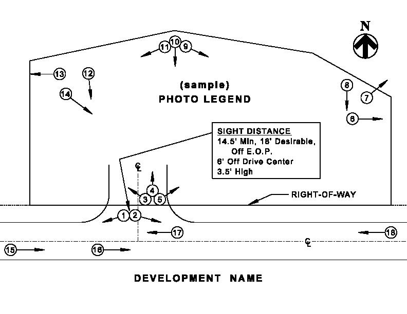
3.4.7 Design Exception Report - There will be occasions when projects will not be designed to the applicable standards, policies and specifications contained and referenced within this manual. Should this occur, the concept/site plan submittal shall also include a Design Exception Report.
If a range of values is contained in the standards, policies, and specifications, the lowest or highest value, whichever is more appropriate, is to be used as the minimum or maximum accepted value, respectively. Any improvement, either permanent or temporary, that creates a nonstandard condition shall be documented by an approved Design Exception Report.
Special Use Permits - Improvements and Developments Page | 3-16 9/25/2023 Design Criteria Manual
The report shall request an exception specifically for any and all criterion which falls outside of the normal published range of application The request for a design exception shall include the following:
1) A discussion of the proposed work
2) A discussion of the exception being requested and what the estimated cost (in both time and money) would be necessary to achieve full standards (i.e., explain the burden which would be encumbered in order for the design to meet the published standard.)
3) Proposed mitigation measures for the exception (i.e., signing, pavement marking, lighting, rumble strips, etc.)
4) The expected safety of the section constructed with the design exception.
The format of the Design Exception Report supporting the design exception shall follow the order of the items listed above. Each Design Exception being requested within the document shall conclude with a signature and date line for the St. Louis County Staff Member responsible for the review to either "Approve" or "Reject" the request. See Figure 3.4-1 for an example of a "Design Exception Report".
Special Use Permits - Improvements and Developments Page | 3-17 9/25/2023 Design Criteria Manual
Figure 3.4-1 - Design Exception Report
Example Design Exception Report
For: ABC Development
By: John Doe, P.E.
On: January 1, 2016
This project involves the construction of ABC Retail Outlet at the corner of Arterial Parkway and Collector Village Way. Permanent associated roadway improvements include the installation of a widening for a left turn lane. The Traffic Impact Study indicates the need for a left turn lane to be added to Arterial Parkway, for a length of 200 feet. The existing Arterial Parkway is a 4-lane, undivided roadway section with curb and gutter. County Creek Bridge is located in a sag curve approximately 150 feet from the entrance into the outlet.
The existing curve is estimated to have a K value of 63. Because the turn lane extends into the sag curve, the widening in the sag will not meet current design criteria based on the design speed. In addition, the 4-lane bridge will not accommodate the width necessary to carry the turn lane across the bridge. The standard indicates a needed K value of 79 to meet current criteria. The only solution which would result in meeting the prevailing design criteria would be to reconstruct the bridge with an increase in profile grade line elevation of approximately 2 feet. The cost to accomplish this improvement is estimated to be approximately $1,000,000. In addition, the time to design, acquire the private property necessary for the improvement and construction time would push project completion out at least 2 years. We feel this burden is unreasonable and therefore, we are formally requesting an exception to the vertical alignment and the length of the turn lane.
We are proposing to mitigate the vertical alignment and short turn bay length with the installation of a light pole near the bridge, located behind the guardrail. The plans submitted reflect these improvements.
With the proposed mitigation and previous safety record, we believe that construction of the proposed design, with the design exceptions, would not significantly impact the safe operation of this facility.
Special Use Permits - Improvements and Developments Page | 3-18 9/25/2023 Design Criteria Manual
□ □ St. Louis County Representative's Signature Date Approve Reject
UNINCORPORATED SITE PLAN CHECKLIST*
(Form 3.4.8)
Development Name
Submittal Date Engineer
Circle One for Each Item: N/A (Not Applicable) O/P (On Plans) P/S (Plan Sent) ATT (Attached)
Note that "forthcoming" or "to be provided" is not an option
Plan Features:
N/A O/P 1) Location map.
N/A O/P 2) North arrow and Engineer's scale.
N/A O/P 3) All site-specific zoning ordinance conditions.
N/A O/P 4) Present and proposed zoning, proposed use.
N/A O/P 5) P.E. seal and signature
N/A O/P 6) Show and dimension about the centerline of right-of-way, all existing and proposed private and public topographic features (pavement, driveways, sidewalks, etc.) within the site, and abutting or opposite the site.
N/A O/P 7) Show and dimension about the centerline of right-of-way, all existing and proposed, public and private street right-of-ways, easements and TSCL's within the site, and abutting or opposite the site.
N/A O/P 8) Book and page in which right-of-way, easement and TSCL has been recorded.
N/A O/P 9) Existing and proposed storm sewers, bridges, culverts, sink holes, springs, basins within site and abutting site.
N/A O/P 10) Existing and proposed 2-foot interval contours based upon U.S.G.S. datum within site and extending 100 feet beyond site.
N/A O/P 11) Cross access within site and abutting site, as required.
N/A O/P 12) Corner triangle (Figure 5.9-3) at all intersections.
N/A O/P 13) Geotechnical Statement with P.E. seal and signature, when applicable.
* Additional requirements may be necessary depending on the particular site development.
Special Use Permits - Improvements and Developments Page | 3-19
Manual
9/25/2023 Design Criteria
UNINCORPORATED SITE PLAN CHECKLIST*
(Form 3.4.8)
Development Name
Standard Plan Notes:
N/A O/P 14) All proposed improvements will conform to related St. Louis County Capital Improvement Project No. ________
N/A O/P 15) All sidewalks to be constructed to current St. Louis County ADA Standards.
N/A O/P 16) Prior to improvement/construction plan approval, the engineer shall provide a signed and sealed note on the plans for both residential and commercial projects, stating that the unimproved existing sidewalk along the project frontage meets current St. Louis County ADA Standards.
N/A O/P 17) All proposed improvements shall be constructed to St. Louis County Standards.
N/A O/P 18) All grading and drainage to be in conformance with St. Louis County and MSD Standards.
N/A O/P 19) All driveways intersecting St. Louis County Arterial and classified roadways shall have on-site turnaround capability, as directed by the St. Louis County Department of Transportation
N/A O/P 20) Storm water shall be discharged at an adequate natural discharge point. Sinkholes are not adequate discharge points.
N/A O/P 21) Improve ________ _______to one-half of a _________right-of-way and a ______________ pavement or minimum ________________ pavement. (Show and reference the appropriate typical section on the plan per Standard Drawings C203.66 through C203.91 or applicable Planning Typical Section from the Design Criteria Manual.).
N/A O/P 22) Provide a sidewalk conforming to St. Louis County ADA standards adjacent to ___________________________. (Sidewalk is to be shown along the entire frontage of the property adjacent to a County roadway. Any variation to this will be determined during construction plan review.)
N/A O/P 23) Access to this development from _______________________________ shall be via __ ____ entrance(s) located _______ to provide required sight distance and constructed to St. Louis County standards as directed by the St. Louis County Department of Transportation.
* Additional requirements may be necessary depending on the particular site development.
Special Use Permits - Improvements and Developments Page | 3-20 9/25/2023 Design Criteria Manual
____________.
UNINCORPORATED
SITE PLAN CHECKLIST*
(Form 3.4.8)
Development Name
Standard Plan Notes:
N/A O/P 24) All proposed access to St. Louis County roads for new development shall meet minimum St. Louis County sight distance requirements.
N/A O/P 25) Any entity that performs work on St. Louis Countymaintained property shall provide the County with a Certificate of Insurance evidencing general liability coverage (bodily injury and property damage) in the amounts specified as the limits of liability set by the State for public entities. Such certificate shall include "St. Louis County" as an additional insured and shall be provided prior to the issuance of any permit. Certificate shall provide for a 30-day policy cancellation notice to St. Louis County. Upon request, the County will provide the specific amounts for both per person and per occurrence limits.
N/A O/P 26) All above-ground utilities or other potential obstructions within the St. Louis County road right-of-way, shall have a minimum setback, as directed by the St. Louis County Department of Transportation, as prescribed in Section 5.10 of the St. Louis County Design Criteria Manual "Roadside Design Requirements"
N/A/ O/P 27) No slopes shall exceed 3 (horizontal) to 1 (vertical) within St. Louis County Right-of-Way unless justified by a geotechnical report, which has been approved by St. Louis County, and designed in full compliance with roadside safety standards.
N/A O/P 28) Required roadway improvements must be completed prior to issuance of building permits in excess of 60% for subdivisions or prior to occupancy for single lot developments.
N/A O/P 29) Existing ponds to be eliminated shall be de-watered at a reasonable rate as not to adversely affect downstream properties.
N/A O/P 30) Each stub street shall have a sign posted by developer advising: "This street to be extended as part of future development."
N/A O/P 31) A land disturbance permit will be required.
N/A O/P 32) The permit process requires improvement plan submittal to the Department of Transportation.
* Additional requirements may be necessary depending on the particular site development.
Special Use Permits - Improvements and Developments Page | 3-21 9/25/2023
Criteria Manual
Design
UNINCORPORATED SITE PLAN CHECKLIST*
(Form 3.4.8)
Development Name
Supplemental Documents Required to be Submitted with Plan:
N/A ATT 31) Photos identified on a location key showing photo directions and numbers. (See Section 3.4.6, Design Criteria Manual). Photos 1 & 2 below are to be taken at all proposed access locations to verify whether or not there is adequate sight distance.
Photos shall be labeled and identified as shown. If it appears that there is not adequate sight distance a plan and profile of sight lines will be required.
N/A P/S 32) MoDOT concept approval, as required.
N/A ATT 33) Traffic Impact Study including traffic signal warrants, as required.
N/A P/S 34) Sight distance exhibits at all uncontrolled intersections and entrances.
N/A P/S 35) Turning movement exhibits, as required.
N/A ATT 36) Transmittal letter to MSD for all projects within MSD jurisdiction to provide them the opportunity for up-front review of Phase II, Post Construction Stormwater Management Requirements.
* Additional requirements may be necessary depending on the particular site development.
Special Use Permits - Improvements and Developments Page | 3-22 9/25/2023
Design Criteria Manual
UNINCORPORATED SITE PLAN CHECKLIST*
(Form 3.4.8)
Development Name
N/A ATT 37) Pre-construction and post-construction storm water runoff calculations. Post-construction storm water runoff shall mimic pre-construction runoff to the maximum extent possible.
N/A P/S 38) Approved Flood Plain Study reflecting proposed 100-year flood elevation and existing 100-year flood plain limits, as required.
N/A ATT 39) Geotechnical report signed and sealed by a professional engineer, as required.
N/A P/S 40) Street stub report, as required.
This is to acknowledge that I personally checked the attached plan and related documents for conformance to the Concept / Site Plan Checklist.
Signature Date
Please contact Civil Plan Review at (314) 615-8517 for a preliminary discussion regarding anticipated improvements and access requirements prior to first submittal of the concept / site plan. Please keep in mind that items discussed are subject to change when concept / site plan is submitted and reviewed.
* Additional requirements may be necessary depending on the particular site development.
Special Use Permits - Improvements and Developments Page | 3-23 9/25/2023 Design Criteria Manual
SEAL
UNINCORPORATED SITE PLAN CHECKLIST* (Form 3.4.8)
Development Name
Additional Notes / Requirements:
* Additional requirements may be necessary depending on the particular site development.
Design Criteria Manual
Special Use Permits - Improvements and Developments Page | 3-24
9/25/2023
MUNICIPAL SITE PLAN CHECKLIST*
(Form 3.4.9)
Development Name
Submittal Date Engineer
Circle One for Each Item: N/A (Not Applicable) O/P (On Plans) P/S (Plan Sent) ATT (Attached)
Note that "forthcoming" or "to be provided" is not an option
Plan Features:
N/A O/P 1) Location map.
N/A O/P 2) North arrow and Engineer's scale.
N/A O/P 3) All site-specific zoning ordinance conditions.
N/A O/P 4) Present and proposed zoning, proposed use.
N/A O/P 5) P.E. seal and signature.
N/A O/P 6) Show and dimension about the centerline of right-of-way, all existing and proposed private and public topographic features (pavement, driveways, sidewalks, etc.) within the site, and abutting or opposite the site.
N/A O/P 7) Show and dimension about the centerline of right-of-way, all existing and proposed, public and private street right-of-ways, easements and TSCL's within the site, and abutting or opposite the site.
N/A O/P 8) Book and page in which right-of-way, easement and TSCL has been recorded.
N/A O/P 9) Existing and proposed storm sewers, bridges, culverts, sink holes, springs, basins within site and abutting site.
N/A O/P 10) Existing and proposed 2-foot interval contours based upon U.S.G.S. datum within site and extending 100 feet beyond site.
N/A O/P 11) Cross access within site and abutting site, as required.
N/A O/P 12) Corner triangle (Figure 5.9-3) at all intersections.
* Additional requirements may be necessary depending on the particular site development.
Special Use Permits - Improvements and Developments Page | 3-25
Manual
9/25/2023 Design Criteria
MUNICIPAL SITE PLAN CHECKLIST*
(Form 3.4.9)
Development Name
Standard Plan Notes:
N/A O/P 13) All proposed improvements will conform to related St. Louis County Capital Improvement Project No.
N/A O/P 14) All sidewalks to be constructed to current St. Louis County ADA Standards.
N/A O/P 15) Prior to improvement/construction plan approval, the engineer shall provide a signed and sealed note on the plans for both residential and commercial projects stating that the unimproved existing sidewalk along the project frontage meets current St. Louis County ADA Standards.
N/A O/P 16) All proposed improvements shall be constructed to St. Louis County Standards.
N/A O/P 17) All grading and drainage to be in conformance with St. Louis County and MSD Standards.
N/A O/P 18) All driveways intersecting St. Louis County Arterial and classified roadways shall have on-site turnaround capability, as directed by the St. Louis County Department of Transportation.
N/A O/P 19) Storm water shall be discharged at an adequate natural discharge point. Sinkholes are not adequate discharge points.
N/A O/P 20) Improve ___________________to one-half of a ______right-of-way and a ______________ pavement or minimum ________________ pavement. (Show and reference the appropriate typical section on the plan per Standard Drawings C203.66 through C203.91 or applicable Planning Typical Section from the Design Criteria Manual).
N/A O/P 21) Provide a sidewalk conforming to St. Louis County ADA standards adjacent to ___________________________. (Sidewalk is to be shown along the entire frontage of the property adjacent to a County roadway. Any variation to this will be determined during construction plan review.)
* Additional requirements may be necessary depending on the particular site development.
Special Use Permits - Improvements and Developments Page | 3-26 9/25/2023 Design Criteria Manual
________ ____________.
MUNICIPAL SITE PLAN CHECKLIST*
(Form 3.4.9)
Development Name
Standard Plan Notes:
N/A O/P 22) Access to this development from __________________ shall be via ___ ___ entrance(s) located _______ to provide required sight distance and constructed to St. Louis County standards as directed by the St. Louis County Department of Transportation.
N/A O/P 23) All proposed access to St. Louis County roads for new development shall meet minimum St. Louis County sight distance requirements.
N/A O/P 24) Any entity that performs work on St. Louis Countymaintained property shall provide the County with a Certificate of Insurance evidencing general liability coverage (bodily injury and property damage) in the amounts specified as the limits of liability set by the State for public entities. Such certificate shall include "St. Louis County" as an additional insured and shall be provided prior to the issuance of any permit. Certificate shall provide for a 30-day policy cancellation notice to St. Louis County. Upon request, the County will provide the specific amounts for both per person and per occurrence limits.
N/A O/P 25) All above-ground utilities or other potential obstructions within the St. Louis County road right-of-way, shall have a minimum setback, as directed by the St. Louis County Department of Transportation, as prescribed in Section 5.10 of the St. Louis County Design Criteria Manual ‘Roadside Design Requirements’.
N/A/ O/P 26) No slopes shall exceed 3 (horizontal) to 1 (vertical) within St. Louis County Right-of-Way, unless justified by a geotechnical report, which has been approved by St. Louis County, and designed in full compliance with roadside safety standards.
N/A O/P 27) Prior to "Special Use Permit" issuance by the St. Louis County Department of Transportation, a special cash escrow or a special escrow supported by an Irrevocable Letter of Credit, may be required to be established with the St. Louis County Department of Transportation to guarantee completion of the required roadway improvements.
* Additional requirements may be necessary depending on the particular site development.
Special Use Permits - Improvements and Developments Page | 3-27 9/25/2023 Design Criteria Manual
MUNICIPAL SITE PLAN CHECKLIST*
(Form 3.4.9)
Development Name
Supplemental Documents Required to be Submitted with Plan:
N/A ATT 28) Photos identified on a location key showing photo directions and numbers. (See Section 3.4.6). Photos 1 & 2 below are to be taken at all proposed access locations to verify whether or not there is adequate sight distance.
Photos shall be labeled and identified as shown. If it appears that there is not adequate sight distance a plan and profile of sight lines will be required.
N/A P/S 29) MoDOT concept approval, as required.
N/A ATT 30) Traffic Impact Study including traffic signal warrants, as required.
N/A P/S 31) Sight distance exhibits at all uncontrolled intersections and entrances.
N/A P/S 32) Turning movement exhibits, as required.
N/A ATT 33) Municipal conceptual approval.
* Additional requirements may be necessary depending on the particular site development.
Special Use Permits - Improvements and Developments Page | 3-28 9/25/2023
Criteria Manual
Design
MUNICIPAL SITE PLAN CHECKLIST*
(Form 3.4.9)
Development Name
N/A ATT 34) Transmittal letter to MSD for all projects within MSD jurisdiction to provide them the opportunity for up-front review of Phase II, Post Construction Stormwater Management Requirements.
N/A ATT 35) Pre-construction and post-construction storm water runoff calculations. Post-construction storm water runoff shall mimic pre-construction runoff to the maximum extent possible.
This is to acknowledge that I personally checked the attached plan and related documents for conformance to the Concept / Site Plan Checklist.
Signature
Date
Please contact Civil Plan Review at (314) 615-8517 for a preliminary discussion regarding anticipated improvements and access requirements prior to first submittal of the concept/site plan. Please keep in mind that items discussed are subject to change when concept / site plan is submitted and reviewed.
* Additional requirements may be necessary depending on the particular site development.
Special Use Permits - Improvements and Developments Page | 3-29 9/25/2023 Design Criteria Manual
SEAL
MUNICIPAL SITE PLAN CHECKLIST* (Form 3.4.9)
Development Name
Additional Notes / Requirements:
* Additional requirements may be necessary depending on the particular site development.
Design Criteria Manual
Special Use Permits - Improvements and Developments Page | 3-30
9/25/2023
3.5 Specific Requirements for the Preparation of Improvement Plans
3.5.1 Plan Sheet Size - Where practical, plan and profile sheets 24 inches by 36 inches are preferred. Improvement plans shall be limited to a maximum sheet size of 30 inches by 42 inches except for plans subject to the subdivision ordinance; which limits exhibits to 24 inches by 36 inches.
3.5.2
Plan Sheet Scale
1) Not-to-scale (NTS) details are discouraged and may be rejected.
• Exception: Typical section details.
2) Traffic signal improvement plans shall be drawn to scale at 1" = 20'.
3) Plan view sheets (with the exception of traffic signal improvement plans) may be any scale from 1" = 10' through 1" = 50', so long as the scale is an increment of 10 feet and is sufficiently clear in reflecting the details of the proposed construction.
• Roadway plan view recommended scale: 1" = 20'.
4) Profile sheets may be plotted at any scale between 1" = 50' (horizontal) and 1" = 10' (vertical), and 1" = 5' (horizontal and vertical)
• Roadway view recommended scale: 1" = 20' (horizontal) and 1" = 5' (vertical).
• Pipe profile recommended scale: 1" = 20' horizontal and 1" = 5' (vertical).
5) Cross sections may be plotted at any scale between 1" = 50' (horizontal) and 1" = 10' (vertical), and 1" = 5' (horizontal and vertical).
• Cross Section recommended scale: 1" = 5' (horizontal) and 1" = 5' (vertical).
• Culvert section recommended scale: 1" = 5' (horizontal) and 1" = 5' (vertical).
3.5.3 Plan Sheet Types - The specific plan sheets required for any given development will vary based on the types of improvements proposed. In all cases, sufficient information shall be provided to fully describe the proposed improvements to the satisfactionof the Department.
All construction details pertaining to roadway improvements (e.g., pavement widening, curbing, sidewalk, unpaved areas, entrances, etc.) shall be shown as a typical section and in plan and profile. The improvement plan shall also include and identify all planned future roadway construction improvements by others in the vicinity of the proposed site development.
Special Use Permits - Improvements and Developments Page | 3-31 9/25/2023 Design Criteria Manual
Plan sets will generally consist of, but not be limited to, the following:
1) General (All Improvement Plan Types):
a) Cover Sheet (Required) - The cover sheet is to be the first sheet in a set of plans. The cover sheet shall contain the location and the extent of the work to be performed. The cover sheet should also include all of the relevant project information such as the project name, roadway ADT, design speed, development number, job number, plan number, sheet index, legend of symbols, general notes, and a location map with north arrow.
• Single plan page submittals are acceptable for single lot developments where cover sheet requirements and improvement plan requirements can be met on the same sheet.
b) Right-of-way and easement dedication plats.
c) Other drawings as necessary to illustrate the proposed improvements.
d) All existing and proposed improvements.
e) Two-foot contours
2) Approved Concept/Site Plan - Complete Concept/Site Plan as approved
3) Roadway Improvement Plan:
a) Typical sections;
b) Survey ties and benchmarks;
c) Plan/profile sheets;
d) Superelevation detail sheet;
e) Warping details;
f) Cross sections;
g) Grading Plan;
h) Driveway cross sections/profiles;
i) Traffic control sheets
4) Storm Sewer, Sanitary Sewer, Water Resource Improvement Plan:
a) Plan view sheets;
b) Sanitary sewer profile sheets;
c) Storm sewer profile sheets;
d) Detention/retention basin cross section sheets;
e) Storm water BMP plan/profile/planting sheets;
f) Drainage Area Maps;
g) Hydraulic computation sheets
Special Use Permits - Improvements and Developments Page | 3-32 9/25/2023 Design Criteria Manual
5) Traffic Signal Improvement Plan:
a) Plan view/general traffic signal layout sheets;
b) Signal equipment/materials and quantity Sheets.
6) Structural Improvement Plan:
a) Plan view sheets;
b) Structural detail sheets;
c) Retaining wall profile sheets
3.5.4 Specific Plan Sheet Requirements:
1) Cover Sheet - The cover sheet shall be included for all improvement plans submitted for approval. Specific details shall include, but not be limited to, the following:
a) All information required in Section 1003.179 of the Zoning Ordinance and/or Sections 1005.050 and 1005.060 of the Subdivision Ordinance, where applicable.
b) Key map showing the relationship of the area to be subdivided to the tract and which shall reflect areas of the tract previously subdivided plus adjacent streets.
c) Location map showing a broader view of the project location with respect to the surrounding roadway network, including North arrow.
d) List of the standards and specifications followed
e) Legend of symbols
f) General Notes
g) Metropolitan St. Louis Sewer District (MSD) - Reference (P-number) and PAC number where applicable.
h) Listing of applicable roadway design designation information:
i) Functional roadway classification;
ii) Design year;
iii) Current and projected traffic volumes;
iv) Directional distribution;
v) Truck percentage, if known;
vi) Posted speed;
vii) Design speed.
i) Title block showing name and address of developer and engineering firm.
Special Use Permits - Improvements and Developments Page | 3-33 9/25/2023 Design Criteria Manual
j) One or more benchmarks with level notes, in or near the site or subdivision, to which the development is referenced. Refer to 4.5 4, Benchmarks for additional requirements.
k) Existing and proposed survey monuments on site plans for single lot developments or on proposed record plat for subdivisions.
2) Approved Concept/Site Plan - The final improvement plan set shall include plan sheets depicting the complete site development as approved with the concept/site plan. All sheets approved with the Concept/Site Plan review excepting the supplemental documents shall be included.
3) Grading Plan:
a) Existing and proposed contours shall be plotted at two (2) foot intervals. Contours shall be shown extending 100 feet beyond the subject site. Contour intervals for Grading Plans other than the above shall require Departmental approval.
b) Site grading shall be compatible with the ultimate roadway elevations.
c) Sink hole locations shall be shown and labeled.
d) See the grading plan checklist for additional requirements.
4) Typical Sections:
a) Typical section detail clearly noting:
i) Existing features;
ii) Proposed features;
iii) Pavement Section;
iv) Lane usage;
v) Lane widths;
vi) Cross slope;
vii) Construction centerline.
b) Applicable station range noted under each typical section.
5) Plan View:
a) North Arrow (North shall be oriented to the top or to the right of the sheet);
b) Graphical Scale;
c) All information required in Section 1005.070 of the Subdivision Ordinance, where applicable.
Special Use Permits - Improvements and Developments Page | 3-34 9/25/2023 Design Criteria Manual
d) Locations of all existing and proposed improvements:
i) Signal equipment (concrete bases, pull boxes, detector loops, cable, underground signal conduit, etc.
ii) Above ground utilities (poles, pedestals, fire hydrants, etc );
iii) Underground utilities (underground vaults, mains, fiber, etc );
iv) Topographic features;
v) Proposed Improvements;
vi) Sewer structures and pipe;
vii) Right-of-way and easements;
viii) Lane usage;
ix) Edge of pavement;
x) Islands;
xi) Medians;
xii) Lane widths;
xiii) Limits of pavement replacement;
xiv) Intersecting streets and driveways;
xv) Existing pedestrian facilities;
xvi) Proposed Pedestrian Facilities - ADA curb ramps shall be labeled with the standard ramp configuration number or site-specific detail reference page number as applicable
e) Construction centerline and stationing shall be established about the original right-of-way centerline, unless otherwise directed by the Department.
i) Grid coordinate pairs at the start and end of the centerline chain;
ii) Bearings;
iii) Station equations;
iv) Identify curve PI's PC's, PT's, POT's;
v) Curve data including delta and direction;
vi) Degree of curvature;
vii) Radius;
viii) Length;
ix) Etc.
Special Use Permits - Improvements and Developments Page | 3-35 9/25/2023 Design Criteria Manual
f) All existing features within the construction limits to be marked as follows:
i) Adjust to grade (ATG);
• Example: Adjusting a manhole top to the proposed roadway grade;
ii) Adjust to Grade By Others (ATGBO);
• Example: A utility relocation which will be performed by the utility rather than the developer;
iii) To Be Removed (TBR);
• Example: An existing feature which will be permanently removed;
iv) To Be Removed and Replaced (TBR&R);
• Example: An existing item which will be removed temporarily and reinstalled at the completion of construction activities, such as a mailbox.
g) The location and type of Joint shall be indicated when it differs from the Pavement Construction Details on Standard Drawings C502.01 to C502.02, and C502.13 to C502.14. All longitudinal joints shall be constructed along proposed lane lines as directed by the Department.
h) The type and location of entrance construction or intersection construction shall be indicated (Refer to Standard Drawings C608.00 through C608.05).
i) Compatibility with existing facilities shall be shown for streets, entrances, and structures adjacent to and across from the subject site.
6) Roadway Profile View:
a) Station/elevation grid;
b) Roadway name;
c) Existing profile, clearly labeled;
d) Proposed profile, clearly labeled;
e) Mathematical profile grade elevations shall be shown at twenty-five (25) foot intervals on vertical curves and fifty (50) foot intervals on tangent sections for all roadway construction. Vertical PI’s, curve lengths and K values shall be included for each vertical curve;
f) Underground utilities;
g) Underground sewer pipes and structures.
7) Superelevation Detail Sheet - A Superelevation Diagram shall be shown for each horizontal curve which requires superelevation. The Diagram shall show the relationship between the profile grade elevation and edge of pavement elevation at the beginning and end of each rotation transition, transition lengths, and the ratio of the transitions on and off the horizontal curve, VPC and VPT stations.
Special Use Permits - Improvements and Developments Page | 3-36 9/25/2023 Design Criteria Manual
8) Warping Details - Warping details, including elevations shall be provided in conformance with supplemental Drawing 5 5
9) Driveway Cross Sections/Profiles:
a) Station/elevation grid;
b) Driveway centerline station (mainline);
c) Existing profile, clearly labeled;
d) Proposed profile, clearly labeled;
e) Mathematical profile grade stationing and elevations shall be shown at all vertical PI’s, PC’s, and PT’s.;
f) Curve lengths shall be included for each vertical curve, K values may be omitted.;
g) Underground utilities;
h) Underground sewer pipes and structures.
10) Traffic Control Sheets:
a) North Arrow (North shall be oriented to the top or to the right of the sheet);
b) Graphical Scale;
c) Roadway names;
d) Horizontal stationing;
e) The existing and proposed features which will be present at the start and end of the specific traffic control phase;
f) Locations of traffic control signage; distances between signs shall be dimensioned;
g) All signs shall be identified with MUTCD compliant identifiers;
h) Existing striping;
i) Temporary striping locations;
j) Lane usage labels;
k) Channelizer types;
l) Channelizer locations;
m) Pedestrian facility closure locations and signage;
n) Pedestrian facility detour route and signage;
o) Arrow panel locations (as applicable);
p) Changeable message board locations (as applicable);
q) Phase number labels (as applicable).
Special Use Permits - Improvements and Developments Page | 3-37 9/25/2023 Design Criteria Manual
11) Sanitary/Storm Sewer Profile Sheets:
a) Station/elevation grid;
b) Existing and/or proposed ground line, as applicable;
c) Rock line elevation, as applicable;
d) Sewer structures clearly labeled with structure number, station, and offset;
e) Pipe runs clearly labeled with length, Q, and slope;
f) Invert and structure top elevations clearly labeled;
g) Hydraulic grade line, clearly labeled;
h) Underground features which cross any given pipe profile; utilities, other sewer pipes, etc.;
i) Limits of granular backfill and pavement replacement at all crossings of existing roadway surfaces not bored shall be shown;
j) Additional criteria as defined by the MSD Design Manual
12) Drainage Area Maps:
a) Standard plan view information with the following stipulations:
i) Feature labels not critical to the description of the drainage areas may be omitted for clarity;
ii) All storm structure labels shall be shown
b) Existing 2-foot contours, extended offsite by 100 feet;
c) Proposed 2-foot contours, extended offsite by 100 feet;
d) Delineation of drainage areas;
e) Tabulation of runoff details;
f) Additional criteria as defined by the MSD’s Rules and Regulations and Engineering Design Requirements for Sanitary Sewers and Stormwater Drainage Facilities.
13) Cross Section Sheets:
a) Station/elevation grid;
b) All grading details pertaining to the site development shall be shown;
c) Side slopes shall be labelled;
d) Existing and proposed right-of-way and easements shall be shown;
e) Underground utilities;
f) Underground sewer pipes and structures;
g) Cross Sections shall be cut at 50' intervals, at each driveway, and at other sitespecific critical locations as necessary to adequately depict all design elements.
Special Use Permits - Improvements and Developments Page | 3-38 9/25/2023 Design Criteria Manual
14) Traffic Signal Construction Plan Sheets - If the proposed roadway improvements affect an existing traffic signal or if a new traffic signal is to be installed, a traffic signal construction plan shall be required. The Department’s Standard Drawing of Traffic Signal Symbols shall be followed for all symbols with line styles and weights used to represent existing and proposed traffic signal equipment. (See Supplemental Drawing 5 7, Example Signal Plan and Supplemental Drawing 5 6 Signal Plan Symbols). Specific details shall include, but not be limited to, the following:
a) Plan View:
i) General:
A) North Arrow (North shall be oriented to the top or to the right of the sheet);
B) Graphical Scale;
C) NEMA Traffic Signal Phasing Chart (vehicular and pedestrian);
D) Signal Installation Notes
ii) Locations of Existing and Proposed Items:
A) Signal equipment (concrete bases, pull boxes, detector loops, cable, underground signal conduit, etc.);
B) Above ground utilities (poles, pedestals, fire hydrants, etc.);
C) Underground utilities (underground vaults, mains, fiber, etc.);
D) Topographic features;
E) Improvements;
F) Sewer structures and pipe;
G) Right-of-way and easements;
H) Lane usage;
I) Edge of pavement;
J) Islands;
K) Medians;
L) Lane widths;
M) Intersecting streets and driveways;
N) Pedestrian facilities;
Special Use Permits - Improvements and Developments Page | 3-39 9/25/2023 Design Criteria Manual
b) Signal Equipment / Materials and Quantity Sheet:
i) Traffic Signal Items:
A) Item Numbers (listed in numerical order);
B) Description;
C) Unit;
D) Quantity
ii) Pull Box Schedule:
A) Box Number (referenced from plan view sheet);
B) Box Type (concrete-single/double, preformed-size, preformed-size with 1' wide concrete apron).
iii) Signal Base & Equipment Schedule:
A) Base Number (referenced from plan view sheet);
B) Concrete Base Type;
C) Mast Arm or Post Type;
D) Signal Equipment Type
iv) Induction Loop Detector Schedule:
A) Loop Number (referenced from plan view sheet);
B) Size & Type of Loop (Standard 3-turn, Quadrupole 2-4-2);
C) Card position in Rack (inside controller cabinet);
D) Channel Used
15) Traffic Signal Interconnect Plan Sheets - If the proposed roadway improvements affects the County’s underground traffic signal interconnect system, even though the development does not have access via a traffic signal, an interconnect plan shall be required. The Department’s Standard Drawing of Traffic Signal Symbols shall be followed for all symbols with line styles and weights used to represent existing and proposed traffic signal equipment. (See Supplemental Drawing 5.7, Example Signal Plan and Supplemental Drawing 5.6 Signal Plan Symbols). Specific details shall include, but not be limited to, the following:
a) Plan View
iii) General:
E) North Arrow (North shall be oriented to the top or to the right of the sheet);
F) Graphical Scale;
Special Use Permits - Improvements and Developments Page | 3-40 9/25/2023 Design Criteria Manual
G) Signal Interconnect Notes.
iv) Locations of Existing, Relocated or Proposed Items:
O) Signal equipment (pull boxes, cable, underground signal conduit, etc.);
P) Above ground utilities (cabinets, pedestals, fire hydrants, etc.);
Q) Underground utilities (underground vaults, mains, fiber, etc.);
R) Topographic features;
S) Improvements;
T) Sewer structures and pipe;
U) Right-of-way and easements;
V) Edge of pavement;
W) Intersecting streets and driveways;
Special Use Permits - Improvements and Developments Page | 3-41
9/25/2023 Design Criteria Manual
c) Signal Interconnect Equipment / Materials and Quantity Sheet:
ii) Traffic Signal Items:
E) Item Numbers (listed in numerical order);
F) Description;
G) Unit;
H) Quantity.
v) Pull Box Schedule:
C) Box Number (referenced from plan view sheet);
D) Box Type (concrete-single/double, preformed-size, preformed-size with 1' wide concrete apron).
Special Use Permits - Improvements and Developments Page | 3-42 9/25/2023 Design Criteria Manual
Chapter 4 Access Management Guidelines
4.0 Introduction - Access management involves the thoughtful planning and design of points of access to the public roadway system, including both public roads and private driveways. Sound access management can have a profound impact on roadway safety and the ability of roads to successfully carry traffic. Failure to properly manage access can result in congestion, excessive delay, safety concerns and diminish the public’s investment in the roadway system.
The standards presented herein are intended to establish guidelines for access management as it relates to the St. Louis County Road System The standards assume jurisdictional uniformity in the design and provision of access to roadway facilities operated by the St. Louis County Department of Transportation The standards apply to a variety of situations, including longrange planning, project planning and design, right-of-way acquisition, redesign of existing arterial corridors, and driveway permitting Uniform standards are intended to improve the safety, effectiveness, and efficiency of the St. Louis County Road System.
Within the context of this plan, the word "shall" implies a mandatory standard, the word "should" represents an advisory recommendation, and the word "may" suggests a permissive condition It should be noted that several other access management plans and resources were used in the development of this plan (as cited in the "Resources" section) Where appropriate, the information gathered from these references was adapted to better reflect the needs and characteristics of the St. Louis County Road System.
4.1 Analysis of Retrofit and Permit Applications - Where access is being managed on an existing roadway (a retrofit or permit project), it is often not possible to incorporate and attain all of the access management principles contained herein due to economic, physical, or other constraints Care must be taken to balance economic interests with transportation needs Economic impacts to business must be carefully considered and efforts must be made to mitigate those impacts. Collaboration with property owners and other stakeholders is the most effective method to achieve improvements that satisfy both operational and economic needs.
The collaboration process should begin in the early stages of project development. Department staff should discuss the fundamentals and benefits of managed access with the stakeholders. Emphasis should be placed on safety and operational benefits and how those benefits can have a positive impact on property values and the business climate. The requirements of potential traffic analyses shall be discussed at this point. The goal of the process should be to produce acceptable operational and safety impacts, while gaining consent of the stakeholders.
In cases where the access management criteria cannot be met, a detailed analysis should be performed to determine the optimum solution. This solution should strive to improve safety and operations along the roadway and maintain optimal flow on the transportation system and insure adequate access to the adjoining properties. In all cases, St. Louis County sight distance requirements supersede access management allowances.
Access Management Guidelines Page | 4-1 9/25/2023 Design Criteria Manual
4.2 Clearance of Functional Areas of Interchanges - Adequate space is needed for traffic to make the transition from a road with interchanges to a road with at-grade access points The functional area of the interchange is the area in which merging and diverging of traffic takes place Drivers must travel along an exit ramp, find acceptable gaps, change lanes (weave), and merge within this distance.
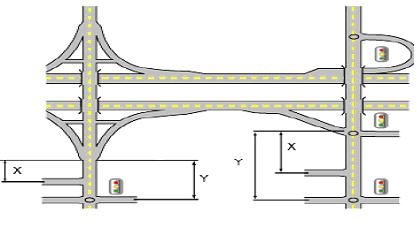
A safe distance for this activity to occur should be provided from the end of the off ramp to the first driveway, median opening, or intersection with a public road. (This is measured from the point of intersection of the ramp baseline and roadway centerline.) When only right turns into or out of driveways or public roads are involved, a shorter clearance area may be used.
X = Distance from baseline on- or off-ramp to the nearest right-in, right-out driveway/public road intersection.
Y = Distance from baseline off-ramp to first major public road intersection, full median opening, or left-turn opportunity.
* Left turns should not be allowed in this section of roadway The public road intersection is likely to become a signalized intersection as the interchange area develops Right-in, right-out driveways configuration should include a non-traversable median.
Note: All ramp measurements are taken to or from baseline ramp.
Access Management Guidelines Page | 4-2 9/25/2023
Criteria Manual
Design
Figure 4.2-1 - Parkway Interchange Clearance
Type of Area Distance from Ramp to RightIn, Right-Out Driveway (X) Distance to First Major Public Road Intersection, Full Median Opening, or Left-Turn Opportunity (Y)* Major: MoDOT, Interstate 750 feet - 1,320 feet 1,320 feet - 2,640 feet Minor: St. Louis County Principal Arterials and Parkways 600 feet 1,320 feet
Table 4.2-1 - Interchange Area Clearance
Any clearance of less than the range contained in the above table should be supported by a study of alternatives to ensure safety and traffic flow All reasonable alternatives, including relocating the interchange to a different location should be considered.
4.3 At-Grade Intersections Spacing - The proper spacing between public roadway and their intersections (both signalized and unsignalized) is an important access management issue. As the number of intersections per mile increases, the opportunity for crashes and the potential obstruction of through traffic increases. Conversely, an adequately dense street network is necessary to prevent adverse travel and to avoid oversaturation of collector roads.
The minimum spacing of signalized intersections is mainly intended to preserve efficient traffic flow and progression on urban arterial roadways Adequate spacing allows traffic signals to be effectively interconnected and synchronized, which will tend to reduce rear-end collisions and "stop and go" driving that increases congestion, delay and air pollution When the spacing between signals is too close, the ability of the arterial to carry through traffic will decrease, travel speeds may decrease, and delays and excessive queues may develop at intersections.
This guideline provides for adequate spacing between street intersections. St. Louis County Principal Arterials are intended to serve through traffic and should have street intersections that are spaced the farthest apart. St. Louis County Minor Arterials and Collector Streets provide some service to through traffic but also collect and distribute traffic from adjacent land uses. Local Roads provide direct access to properties; therefore, they can be placed closer together.
Table 4.3-1 demonstrates minimum spacing requirements for various road classifications. For instance, a driver traveling on a principal arterial should not encounter a signalized intersection more often than every 1320 feet While traveling on that same road an intersection of any kind should not be encountered more often than 660 feet.
- Intersection Spacing
* Un-signalized locations shall be examined closely for a potential need for a signal in the future.
All potential signalized intersections shall satisfy the traffic signal warrants specified by the Manual on Uniform Traffic Control Devices (MUTCD), current edition, preferably Warrant 1 (Condition A or B): Eight-Hour Vehicular Volume Also, the installation of a traffic signal should be supported by an engineering study that demonstrates that progression along the arterial would not be compromised Installations should generally serve both sides of the street and should preferably provide connections to public streets and/or multiple users.
Access Management Guidelines Page | 4-3 9/25/2023 Design Criteria Manual
Roadway Classification Signalized Un-signalized * Roundabout Principal Arterial 1320 660 Varies by Location, Departmental Approval Required Minor Arterials and Collectors 660 460 Varies by Location, Departmental Approval Required Local Roadways Generally Not Permitted 360 Varies by Location, Departmental Approval Required
Table 4.3-1
4.4 Raised Medians - Raised medians are the most effective access management strategy on high-volume urban routes Roadways with raised medians are at least 25 percent safer than multilane undivided sections and 15 percent safer than two-way left-turn lane cross-sections in such high traffic situations.
In general, use of raised medians should be considered where current and projected traffic volume is greater than 28,000 Average Weekday Traffic (AWT) Raised medians are especially recommended in corridors where the traffic volume is high, the density of commercial driveways is high, and other access management strategies such as driveway consolidation and corner clearance are not practical Raised medians should be incorporated on arterial facilities with three or more through traffic lanes in each direction.
4.5 Median Opening Spacing - Openings in raised medians should only be provided to accommodate turning traffic in locations where this can be safely done.
A full opening allows turns to be made in both directions and generally should not be permitted; a directional opening allows left turns in only one direction. Where openings are approved, an adequate spacing between them is necessary to allow for weaving of traffic, to preserve traffic flow, and to provide for safe lane changes and turns. Any consideration for a median opening will require turn pockets of sufficient length to satisfy the predictable left turn demand. An example of a directional median would be one that allows left turns into a driveway but does not allow left turns to be made out. See Figure 4.5-1.
Median openings should not be allowed under the following circumstances:
• On Parkways, except for approved signalized intersections.
• Within the functional area of an interchange
• Within the functional area of an intersection between two public roads
• At locations that have a history of high accident rates
Under conditions of inadequate sight distance, median openings shall not be allowed.
Traffic analyses should support the required length of queue storage for major traffic generators such as a shopping mall or industrial plant.
4.5.1 Accommodating Safe U-Turns - In cases where left turns are restricted by lack of median openings, care must be taken to allow for U-turns to be made in a safe manner at select downstream locations U-turns can be safely accommodated through a variety of means, including signal phasing and timing, pavement widening, and including physical design features such as turning lanes and “jug handles” type configuration. Where U-turns cannot be made safely, they should be explicitly prohibited. U-turn opportunities should be designed with an appropriate typical design vehicle based on facility type. The minimum design vehicle should be WB-40 (Local articulated vehicle).
Access Management Guidelines Page | 4-4 9/25/2023 Design Criteria Manual
4.6 Auxiliary Acceleration and Turning Lanes - The installation of right-turn acceleration lanes is generally not considered on the St. Louis County roadway system Dedicated left- and right-turn lanes should be provided in situations where traffic volumes and speeds are relatively high, and conflicts are likely to develop at public road intersections and driveways between through and turning traffic Auxiliary lanes are an asset in promoting safety and improved traffic flow in such situations. Some major applications of and considerations for the design of auxiliary lanes are as follows:
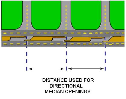
• Installing auxiliary left-turn lanes Such lanes, installed in the roadway center, are intended to remove turning vehicles from the through traffic flow This should reduce the frequency of rear-end collisions at locations where there is considerable left-turn ingress activity, such as major driveways and minor public road intersections Left turn lane warrants are shown in Figures 4.6-1 thru 4.6-3 To use the figures, peak hour traffic counts, including directional splits, will be required.
Access Management Guidelines Page | 4-5 9/25/2023
Criteria Manual
Design
Figure 4.5-1 - Directional Median Openings
Roadway Classification Median Break Spacing Principal Arterial 660 Minor Arterials and Collectors 460 Local Roadways 360
Table 4.5-1 - Directional Median Openings
• The application of auxiliary left-turn lanes should be guided by a traffic analysis In general, auxiliary left-turn lanes must be long enough to accommodate a safe deceleration distance and to provide adequate storage of a queue for expected peak hour turning traffic.
Note: There may be situations where a left turn lane must be considered irrespective of these guidelines, such as locations with high accident rates, insufficient sight distance, unusual geometric conditions, etc.
Management Guidelines Page | 4-6 9/25/2023
Criteria Manual
Access
Design
4.6.1 Left Turn Lanes
The following data are required:
1) Opposing Volume (veh/hr.) - VO - The opposing volume should include only the right-turn and through movements in the opposite direction of the left turning vehicle.
2) Advancing Volume (veh/hr.) - VA - The advancing volume should include the rightturn, left-turn and through movements in the same direction as the left turning vehicle.
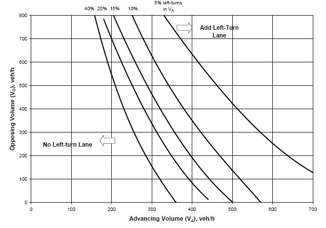
3) Speed (mph) - The design speed.
4) Percentage of left turns in VA.
A left turn lane is not typically needed for left turn volume less than 10 vph. However, criteria other than volume, such as crash experience, may justify a left turn lane.
The appropriate trend line is identified on the basis of the percentage of left-turns in the advancing volume, rounded up to the nearest percentage trend line. If the advancing and opposing volume combination intersects above or to the right of this trend line, a left-turn lane is appropriate.
Access Management Guidelines Page | 4-7 9/25/2023
Criteria Manual
Design
Figure 4.6-1 - Left Turn Lane Guideline for Two-Lane Road <= 40 mph (60 km/h)
From Missouri Department of Transportation Access Management Guidelines
The following data are required:

1) Opposing Volume (veh/hr.) - VO - The opposing volume should include only the right-turn and through movements in the opposite direction of the left turning vehicle.
2) Advancing Volume (veh/hr.) - VA - The advancing volume should include the rightturn, left-turn and through movements in the same direction as the left turning vehicle.
3) Speed (mph) - The design speed.
4) Percentage of left turns in VA
A Left turn lane is not typically needed for an average left turn volume less than 10 vph. However, criteria other than volume, such as crash experience, may justify a left turn lane.
The appropriate trend line is identified on the basis of the percentage of left-turns in the advancing volume, rounded up to the nearest percentage trend line If the advancing and opposing volume combination intersects above or to the right of this trend line, a left-turn lane is appropriate.
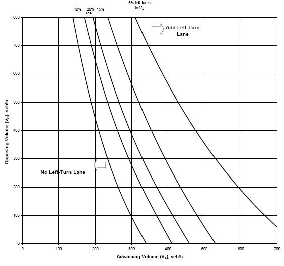
Access Management Guidelines Page | 4-8 9/25/2023 Design Criteria Manual
Figure 4.6-2 - Left Turn Lane Guideline for Two-Lane Road - 45 mph (70 km/h)
From Missouri Department of Transportation Access Management Guidelines
The following data are required:
1) Opposing Volume (veh/hr.) - VO - The opposing volume should include only the right-turn and through movements in the opposite direction of the left turning vehicle.
2) Left-Turn Volume – VL
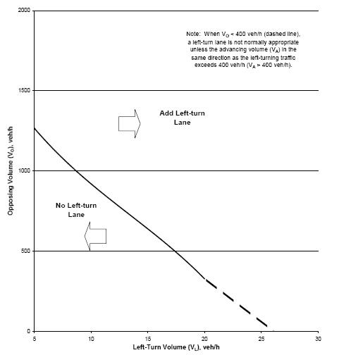
3) Advancing Volume (veh/hr.) - VA - The advancing volume should include the leftturn and through movements in the same direction as the left turning vehicle.
If the opposing and left-turn volume combination intersects above or to the right of the trend line, a left-turn lane is appropriate.
Access Management Guidelines Page | 4-9 9/25/2023 Design Criteria Manual
Figure 4.6-3 - Left Turn Lane Guideline for Four-Lane Undivided Roadway
4.6.2 Right Turn Lanes - Installing auxiliary right-turn lanes The use of dedicated rightturn lanes should be guided by a traffic analysis In general, dedicated right-turn lanes should be provided as shown in the Figures 4.6-4. To use the figures, peak hour traffic counts, including directional splits will be required.
Dedicated right turn lanes should also be strongly considered in situations where:

1) Poor internal site design and circulation leads to backups on the mainline Businesses with short drive-through lanes or poorly-designed parking lots would be prime examples of this situation.
2) The peak hour turning traffic activity is unusually high (e.g. greater than 10 percent of the daily total).
3) The driveway or minor public road intersection is difficult for drivers to see.
4) The driveway entrance is gated or otherwise must be entered very slowly.
5) The intersection or driveway angle is highly skewed.
6) Rear end collision experience is unusually high.
Access Management Guidelines Page | 4-10 9/25/2023 Design Criteria Manual
Figure 4.6-4 - Full Right Turn Lane
From Missouri Department of Transportation Access Management Guidelines
The following data are required:
1) Advancing Volume (veh/hr.) - The advancing volume should include the right-turn, left-turn and through movements in the same direction as the right turning vehicle.
2) Right Turning Volume (veh/hr.) - The right turning volume is the number of advancing vehicles turning right.
3) Speed (mph) - The design speed.
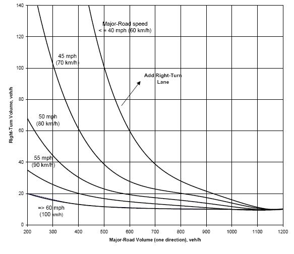
A right turn lane is not typically needed for right turn volumes less than 10 vph. However, criteria other than volume, e.g. crash experience, may justify a right turn lane.
If the combination of major-road approach volume and right-turn volume intersects above or to the right of the speed trend line corresponding to the major road design speed, then a right-turn lane is appropriate.
Access Management Guidelines Page | 4-11 9/25/2023 Design Criteria Manual
Figure 4.6-5 - Right Turn Lane Guideline for Two-Lane Roadway
From Missouri Department of Transportation Access Management Guidelines
The following data are required:
1) Advancing Volume (veh/hr.) - The advancing volume should include the right-turn, left-turn and through movements in the same direction as the right turning vehicle.
2) Right Turning Volume (veh/hr.) - The right turning volume is the number of advancing vehicles turning right.
3) Speed (mph) - The design speed.
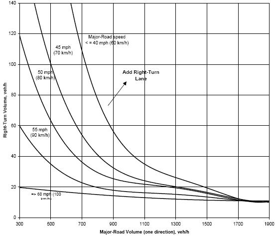
A right turn lane is not typically needed for right turn volumes less than 10 vph. However, criteria other than volume, e.g. crash experience, may justify a right turn lane.
If the combination of major-road approach volume and right-turn volume intersects above or to the right of the speed trend line corresponding to the major road design speed, then a right-turn lane is appropriate.
Access Management Guidelines Page | 4-12 9/25/2023 Design Criteria Manual
Figure 4.6-6 - Right Turn Lane Guideline for Four-Lane Roadway
4.6.3 Offset Right and Left Turn Lanes - Vehicles in the right-turn lane tend to obstruct the vision of drivers waiting at the stop bar of the minor roadway One way to reduce the obstruction of the minor roadway drivers’ view is to offset the right-hand turning bay to the right Similarly, vehicles in the opposing left-turn lane block the views of left-turning vehicles from the opposite direction These conditions are shown in the Figure 4.6-7 below An example intersection with offset right- and left-turn lanes is shown in Figure 4.6-8 Offsetting left-turn lanes to the left as far as practical improve the visibility of opposing traffic By improving the visibility of opposing traffic, drivers can more effectively use available gaps Offsetting right-turn lanes to the right permits drivers on the minor approach (at the stop bar) to observe oncoming traffic in the near lanes, which allows for more effective use of gaps.
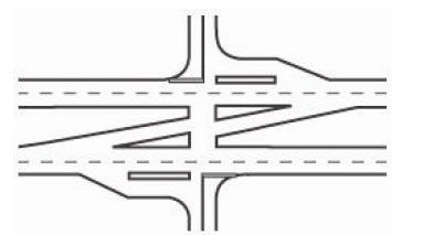
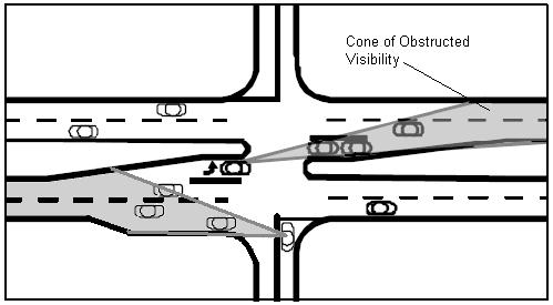
Consideration should be given to offset right and left-turn lanes in locations with high mainline operating speeds, large percentage of turning trucks, unique sight distance issues, or crash experience where investigation of crash diagrams indicates a safety benefit may be obtained from an offset turn lane Care should be taken when implementing offset auxiliary turn lanes to insure the horizontal geometry of the roadway does not negate the line-of-sight improvement.
Access Management Guidelines Page | 4-13 9/25/2023 Design Criteria Manual
Figure 4.6-7 - Cone of Obstructed Visibility
Figure 4.6-8 - Offset Right Turn Lanes
4.7 Two Way Left Turn Lanes - Two-way left-turn lanes (TWLTL) may be effective as an access management tool when used in conjunction with other techniques such as driveway consolidation and corner clearance. TWLTL cross sections work best in situations where traffic volume and the density of driveways is relatively low, and the proportion of left-turning vehicles is relatively high TWLTL's are recommended in places where commercial driveways make up a substantial portion of total driveways and where the percentage of vehicles turning left in peak hour is significant.
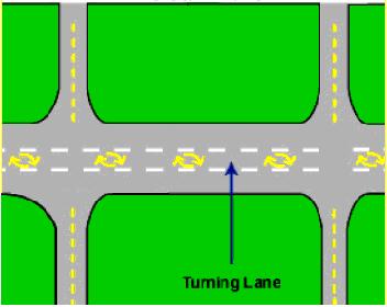
TWLTL's may be inappropriate where the commercial driveway density is above the driveway spacing guideline. Research indicates that when commercial driveway density is high, crash rates increase significantly.
TWLTL configurations are not recommended along high traffic volume (over 28,000 AWT) urban routes; in such situations raised medians are at least 25 percent safer than multilane undivided sections and 15 percent safer than TWLTL cross sections TWLTL configurations generally should not be used on facilities with more than four through-traffic lanes, e.g., to create a "seven lane" facility.
Management Guidelines Page | 4-14 9/25/2023
Criteria Manual
Access
Design
Figure 4.7-1 - Center Two Way Left Turn Lanes
Roadway Classification TWLTL Principal Arterial May be used when appropriate if the design hour volume of opposing direction is between 750 and 1,000 vphpl Minor Arterials and Collectors May be used when appropriate if the design hour volume of opposing direction is between 750 and 1,200 vphpl Local Roadways Generally Not Recommended
Table 4.7-1 - TWLTL Requirements
4.8 Frontage and Backage Roads - Frontage and backage roads provide alternative access to property and help remove turning traffic from the through traffic on a mainline route A frontage road provides alternative access at the front of properties while a backage road provides alternative access at the rear of properties These access management techniques are more appropriate for applications serving properties fronting on principal arterials, although there maybe conditions on minor arterial that warrant consideration as well.
Frontage and backage roads can dramatically improve safety and operations However, a common mistake involves placing frontage or backage roads in close proximity to the mainline Placing frontage roads very close to mainline roads can create additional delay, congestion, and crashes because insufficient storage ("throat length") is provided for entering and exiting vehicles at their terminals.
Frontage and Backage roads should be spaced approximately 360 feet or more from the mainline route at their terminals. Measurements should be taken from pavement edge to pavement edge depending on roadway classification, traffic control type, etc.
The parallel section of frontage roads should be located a minimum of 50 feet from the arterial to minimize interference with operating conditions on the arterial.
4.9 Driveway Spacing - This guideline describes the recommended spacing between private driveways necessary to preserve both safety and traffic flow. Spacing between driveways must be longer in commercial areas than in residential areas.
In order to preserve traffic flow, direct access should be moved to local streets (not arterials) where possible In particular, access for corner lots should be moved to a lower traffic side street whenever possible. Access can often be better accomplished on major streets through such means as frontage and backage roads, joint access, cross access, and shared driveways This guideline only applies where sight distance allows. Driveways should not be allowed where sight distance is inadequate even if the driveway spacing guideline would allow them.
Driveway access should be provided on local and collector streets ("side streets") rather than arterials wherever possible Driveways should also be aligned across the public roadway from each other whenever possible When driveways are not aligned, the spacing should be measured from the closest driveway on either side of the road, except where a non-traversable (e.g., raised) median exists.
Where non-traversable medians exist, shorter driveway spacing may be acceptable for right-in, right-out driveways only (See Section 4.11)
Access Management Guidelines Page | 4-15 9/25/2023 Design Criteria Manual
4.10 Driveway Corner Clearance - Corner clearance represents the distance between the corner of the intersection of two public roadways and the next private driveway It is important to provide enough distance between the corner and the first driveway to effectively separate conflict points and to allow drivers enough time to make safe maneuvers When corners are not adequately cleared, crash rates and delay increase These guidelines correspond to the driveway spacing guidelines for the same roadway classification However, maintaining adequate corner clearance is more critical for safety and operations than mid-block driveway spacing This guideline only applies where the sight distance guideline allows.
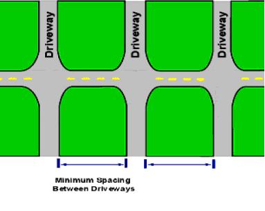
Management Guidelines Page | 4-16 9/25/2023
Criteria Manual
Access
Design
Figure 4.9-1 - Aligned Driveways
Roadway Classification Non-Residential Residential Principal Arterial 660 feet Generally Not Permitted Minor Arterials and Collectors 460 feet 100 (1) Local Roadways 360 feet Generally Not Restricted
Table 4.9-1 - Minimum Driveway Spacing
(1) Local land use planning should be developed to generally preclude residential access to minor arterials or collectors for individual residential lots.
(1) Local land use planning should be developed to generally preclude residential access to minor arterials or collectors for individual residential lots.
(2) Site specific conditions such as terrain, extremely low traffic and or odd shaped parcels may be grounds for a design exception
4.11 Spacing/Clearance for Right-In, Right-Out Driveways - This guideline describes the recommended spacing and corner clearance for driveways along roadways in urban areas that have a non-traversable median and speed limits at or below 45 miles per hour. A nontraversable median restricts left-turn movements into and out of driveways Adequate spacing between driveways and corner clearance are both important to maintain safety and traffic flow. Spacing between driveways should be greater on higher speed routes.
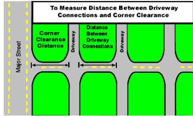
Research and experience in other states indicates that on urban routes where nontraversable medians exist, shorter driveway spacing is acceptable for right-in, right-out driveways However, corner clearance upstream from an intersection or a full access driveway should meet the minimum spacing required for a full access driveway (see table 4.11-1) This guideline provides for double the number of right-in, right-out driveway access points compared to situations where left turns into and out of driveways are permitted It also provides for a shorter clearance distance from corners to the last driveway upstream from the corner For safety reasons, the downstream corner clearance is similar to situations where no nontraversable median is present. This shorter guideline for right-in right-out driveways should not be used where a non-traversable median does not exist (e.g., where there is a continuous left-turn lane.)
Access Management Guidelines Page | 4-17 9/25/2023
Criteria Manual
Design
Figure 4.10-1 - Corner Clearance Distance
Roadway Classification Distance From Non-Residential Driveways Residential Driveways Principal Arterial 660 feet Generally Not Permitted Minor Arterials and Collectors 510 feet 200 feet (1) Local Roadways 410 feet 70 feet (2)
Table 4.10-1 - Minimum Corner Clearance
Experience has shown that a shorter guideline for right-in, right-out drives is appropriate where there is a physical barrier that prevents left turns (e.g., a non-traversable median). Regulatory restrictions on left turns (e.g., "No Left Turn" signs) and small traffic islands do not effectively prevent left and should not be considered as substitutes for nontraversable medians.
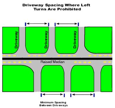
Direct access should be moved to local streets (not arterials and collectors) where possible Access can be better accomplished on major roadways through techniques such as frontage and backage roads, joint access, cross access, and shared driveways. These guidelines only apply where sight distance allows Driveways should not be allowed where sight distance is inadequate even if the spacing guideline would allow them.
Management Guidelines Page | 4-18 9/25/2023 Design Criteria Manual
Access
Figure 4.11-1 - Driveway Spacing Where Nontraversable Median Exists
Roadway Classification Spacing between Right- In, Right-Out Driveways on Roadway with a Restrictive Median Principal Arterial 330 feet Arterials and Collectors 230 feet Local Roadways 180 feet
Table 4.11-1 - Minimum Right-In, Right-Out Driveway Spacing
4.12 Driveway Geometrics - The design of driveways affects the speed of traffic entering and exiting driveways and thus the speed differential between through traffic and turning traffic Large speed differentials are associated with higher crash rates and diminished traffic operations.
Important design features of driveways include width, radii, skew, throat depth, tapers, and grades. Specific design details for these features are explained in Section 5.9
Driveways should always be designed based on the results of an analysis of the traffic likely to use them.
4.12.1 Aligning Driveways Across Roadways - Properly aligned driveways decrease potential traffic conflicts that can result in safety and operational issues. Driveways should be as closely aligned with driveways across roadways without nontraversable medians to the maximum extent possible. Aligning roadway access points directly across from each other allows drivers to more easily scan for conflicts. Eliminating offsets decreases the potential for collisions from vehicles competing for space on the main roadway.
4.12.2 Driveway Throat Length - The throat length is the distance between the street and any parking facilities served by a driveway. An adequate throat length is necessary to keep traffic conflicts within a parking lot to an acceptable level and to provide space on the driveway for incoming and outbound traffic. The following throat-length guidelines should be followed:
• For low traffic volume commercial and driveways, the shortest allowable driveway throat length is 40 feet (about two 20-foot car lengths).
• For medium traffic volume commercial and industrial driveways, the shortest allowable driveway throat length is 80 feet (about four 20-foot car lengths).
• For high-volume driveways such as a shopping center entrance, the adequate throat length should be determined by the results of a traffic analysis.
4.13 Parking on Facilities - Parking should not be allowed on roadways that are primarily intended to serve through-traffic movement (principal arterials) Parking should generally not be allowed on minor arterials and collectors unless there are designated parking areas outside of the travel lanes Parking may be allowed on local roadways.
Generally, only parallel parking is allowed on St. Louis County roadways.
Local governments have the ability to prohibit or restrict parking within their jurisdiction, subject to concurrent legislation in St. Louis County.
Access Management Guidelines Page | 4-19 9/25/2023 Design Criteria Manual
4.14 Definitions
Acceleration Lane - A speed change lane that enables a vehicle entering a roadway to increase its speed to a rate at which it can safely merge with through traffic.
Access - The ability to enter or leave a public street from or at an adjacent driveway or another public street.
Access Management - The control of access to and from the roadway system for the purpose of maintaining safety and optimal flow of traffic.
Auxiliary Lane - A portion of the roadway separate from the thru lanes on the approach to a turning movement that is reserved for storage of vehicles waiting to make the turn.
Average Weekday Traffic (AWT) - The total volume of traffic using the roadway Monday thru Friday of an average sample week divided by 5.
Backage Road - A local street or road running parallel to an arterial for service to abutting properties and for controlling access to the arterials and which provides land access to the rear lot line of the property.
Conflict Point - Any point where the paths of two through or turning vehicles diverge, merge, or cross.
Congestion - See traffic congestion.
Corner Clearance - The minimum dimension, measured along a travel lane between the edge of pavement of an intersecting roadway and the nearest edge of a driveway.
Cross Access - A connection providing vehicular access between two or more contiguous properties so that the motorist need not re-enter the public roadway system in order to visit multiple sites on a single trip.
Driveway - Paved access to a private property.
Design Hour Volume - The hourly traffic volume used to evaluate or design a highway or driveway.
Easement - A grant of one or more property rights by a property owner to or for use by the public, or another person or entity.
Frontage Road - A public or private drive that generally parallels a public road between the right-of-way and the front building setback line The frontage road provides access to private properties while separating them from the arterial street.
Access Management Guidelines Page | 4-20 9/25/2023 Design Criteria Manual
Functional Area (Intersection) - That area beyond the physical intersection of two classified roadways that comprises decision and maneuver distance, plus any required vehicle storage length, and is typically protected through corner-clearance standards and/or driveway connection spacing standards.
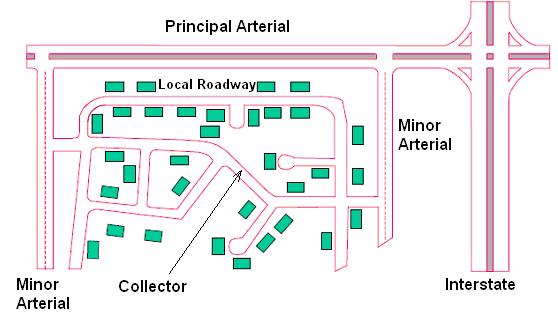
Functional Area (Interchange) - The functional area of the interchange is the area in which merging and diverging of traffic takes place.
Functional Classification - A system used to group public roadways into classes according to their purpose in traffic operation relating to mobility, connectivity and access.
Highway Capacity - The maximum number of vehicles that a highway can handle during a specific amount of time at a given level of service.
Highway System - All public highways and roads maintained by St. Louis County. These include parkways, arterials, collector streets and local roads (Figure 1).
Joint Access (or Shared Access) - A single driveway serving multiple properties.
Level of Service (LOS) - The description of traffic conditions along a given roadway or at a particular intersection The level of service ranges from "A", which is the best, to "F", which is the worst It reflects factors such as speed, travel time, freedom to maneuver, traffic interruptions, and delay.
Local Street - A roadway intended to provide direct access to abutting properties and to roads of higher functional classification.
Access Management Guidelines Page | 4-21 9/25/2023 Design Criteria Manual
Figure 1 - The Highway System
Minor Arterial and Collector - A roadway intended to distribute traffic between a principal arterial and a local roadway where function is balanced between access and thru put. Typically characterized by a significant volume of peak hour traffic.
Peak Hour Traffic - The highest number of vehicles passing over a section of a lane or roadway during any 60 consecutive minutes Typically, there is a peak hour condition in the a.m. and a peak hour condition in the p.m. for which a roadway or intersection is analyzed for capacity and level of service at which time it becomes the design hour.
Principal Arterial - A roadway intended primarily for thru traffic and regional distribution where access is carefully controlled. Typically characterized by substantial volumes of peak hour traffic.
Right-of-Way - Land reserved, used, or slated for use for a highway, street, alley, walkway, drainage facility, or other public purpose.
Side Friction - Driver delays and conflicts caused by vehicles entering and exiting the roadway.
Traffic Analysis - A professional assessment of traffic conditions relating to change of access or development.
Traffic Congestion - A persistent or frequent condition resulting from more vehicles trying to use a given road during a specific period of time than the road can handle with what are considered acceptable levels of delay or inconvenience.
Traffic Impact Study - A report initiated in response to a proposed development that compares the anticipated roadway conditions with and without the development The report may include an analysis of mitigation measures.
Trip Generation - Based upon national averages or local experience, the estimated volume of traffic going to and from a particular land use.
Turn Radius - The radius of an arc that represents the turning path of a vehicle.
Vehicle Trip - The vehicle moving from an origin point to a destination point.
Volume Warrants - The conditions under which traffic management techniques, such as a left-turn or a right-turn lane, are justified For example, the need for a left-turn lane will vary according to the volumes of advancing and opposing traffic, and the percentages of traffic turning left.
Access Management Guidelines Page | 4-22 9/25/2023 Design Criteria Manual
4.15 References
Iowa State University Center for Transportation Research and Education, Iowa Access Management Handbook, October 2000
Missouri Department of Transportation, Missouri Department of Transportation Access Management Manual, November 2006 Edition
Transportation Research Board, Highway Capacity Manual, 2000 Edition
Iowa State University Center for Transportation Research and Education, Access Management Frequently Asked Questions Toolkit, October 2000.
Minnesota Department of Transportation, Access Category System and Spacing Guidelines, March 2002.
Transportation Research Board, Access Management Manual, 2003.
American Association of State Highway and Transportation Officials, A policy on Geometric Design of Highways and Streets, 5th Edition, 2004.
Federal Highway Administration, Access Management for Streets and Highways, June 1982.
Papayannolulis, Gluck, and Feeney, Access Spacing and Traffic Safety.
McHenry County, Illinois, McHenry County Access Management Ordinances, March 1997
Crawford, Bunte, Brammeier, Access Management Plan for the St. Louis County Arterial Road System, December 2001
Management Guidelines Page | 4-23 9/25/2023 Design Criteria Manual
Access
(This Page Intentionally Left Blank)
Access Management Guidelines Page | 4-24 9/25/2023 Design Criteria Manual
Chapter 5 Design Requirements
5.0 Introduction - It is the vision of the County to continue to develop and expand upon a safe, reliable, efficient, integrated, accessible and connected multimodal transportation system that shall promote access, mobility, and health for all users. The design policy set forth in this chapter has been developed to meet the needs of our community by providing the tools to design safe and efficient roadways and pedestrian facilities compliant with current industry standards and federal regulations.
St. Louis County strongly encourages all development within the public Right-of-Way to provide pedestrian, bicycle, and mass transit facilities which are above the minimum requirements of this manual. It is our fervent belief that providing for "Complete Streets" which encourage safe walking, bicycling, transit, and vehicle use for all users, regardless of age or ability promotes healthy, livable communities.
A "Complete Street" is a transportation corridor for all users: pedestrians, bicyclists, transit users, and motorists Complete streets are designed and operated to enable safe accessible travel for all users with a goal towards creating a network of complete streets. Transportation improvements, facilities and amenities that may contribute to complete streets and that are considered as elements of a complete street are: Americans with Disabilities Act (ADA) compliant pedestrian access routes, street and sidewalk lighting, pedestrian, and bicycle facilities; access management; ADA compliant transit stops and stations; context sensitive landscaping, utility relocations and street amenities allowing for efficient levels of service.
All streets shall be graded, and the roadway improved by surfacing. Roadway surfacing shall be in accordance with St. Louis County standards and specifications. All grading and surfacing shall be done under observation and inspection of the Department and shall be subject to its approval. The treatment of the intersection of any new street with a State highway shall be subject to approval by the District Engineer of the Missouri Department of Transportation (MoDOT).
At such times as a subdivision is proposed adjacent to a street that is accepted and maintained by St. Louis County, that street and other streets required shall be improved to handle the increased traffic due to said subdivision as directed by St. Louis County's Highway System Plan, and the additional right-of-way and the cost of improvement of the right-of-way adjacent to the proposed subdivision shall be included in the overall subdivision improvements. The improvements shall be made to current County specifications and standards.
However, a large lot subdivision shall not be required to make the above improvements. The construction of a standard street intersection approach and right-of-way dedication may be required as necessary for the relocation and/or widening of an adjoining County road.
In certain cases involving the subdivision of tracts of property, the reservation of right-of-way access may be required for future road improvements as authorized by the tract's preliminary plat.
Design Requirements Page | 5-1 9/25/2023 Design Criteria Manual
5.1 Adopted Design Publications - Design publications adopted by the St. Louis County Department of Transportation for the improvement of transportation facilities within the public Right-Of-Way include:
1) A Policy on Geometric Design of Highways and Streets (AASHTO - 2018), referenced in this document as the AASHTO Green Book
2) Manual on Uniform Traffic Control Devices (FHWA - Current Version), referenced in this document as the MUTCD
3) Roadside Design Guide 4th Edition (AASHTO – 2011), referenced in this document as the AASHTO Roadside Design Guide
4) Proposed Accessibility Guidelines for Pedestrian Facilities in the Public Right-of-Way (United States Access Board - July 2011), referenced in this document as PROWAG
5) Roundabouts: An Informational Guide, Second Edition; NCHRP Report 672 (FHWA –2010), referenced in this document as the FHWA Roundabout Guide
6) Guide for the Development of Bicycle Facilities, 4th Edition (AASHTO – 2012), referenced in this document as the AASHTO Bike Guide
7) Guidelines of Geometric Design of Very Low-Volume Local Roads (ADT<400) (AASHTO - 2001) - Departmental approval required for the use of this manual.
8) The Metropolitan St. Louis Sewer District Rules and Regulations and Engineering Design Requirements for Sanitary Sewer and Stormwater Drainage Facilities (MSDCurrent Version), referenced in this document as the MSD Design Manual
9) Standard Construction Specifications for Sewer and Drainage Facilities (MSD –Current Version), referenced in this document as the MSD Construction Specifications
10) Metropolitan St. Louis Sewer District Standard Detail Sheets (Current Version), referenced in this document as MSD Standard Details
The above referenced publications shall be used in accordance with the requirements set forth within this manual. Where this manual calls for requirements in excess of the above referenced publications, this manual shall govern.
The design criteria publications used for the development of concept, site and construction plans shall be listed on the cover sheet of the plan set for all projects.
5.2 Introduction to Pavement Design - When construction, maintenance, and rehabilitation costs are considered, the single most costly element of a road system is the pavement structure. In an effort to reduce this cost, the Federal Government and all state highway agencies have sponsored a continuous program and research on pavements over the last 80 years. Although much has been learned, the state of knowledge on the behavior of paving materials remains incomplete. Variables associated with traffic loading, location, and environment make absolutely precise pavement performance predictions for new or rehabilitated sections very difficult.
Design Requirements Page | 5-2 9/25/2023 Design Criteria Manual
The lack of perfect predictive capability, however, does not mean that pavement design activities are useless On the contrary, current design procedures almost always provide pavements that perform at least as long as the target design period with a high degree of reliability These predictions, combined with sound engineering judgment and knowledge of previous pavement performance in an area, is essential for most effectively allocating finite paving resources.
5.2.1 Goals of Pavement Design - The purpose of pavement design activity is to provide the most cost-effective pavement structure while optimizing the level of service provided to road users These goals may frequently conflict For instance, it may be most cost-effective to annually place a low-cost surfacing on a given segment of pavement However, the service disruption required for yearly rehabilitation of the pavement would clearly be unacceptable for all but the lowest level traffic conditions. Conversely, a more initially expensive pavement design with a longer life, such as concrete or "perpetual" asphalt pavement, may ultimately be more cost effective, but funding constraints may also make that choice impractical. Cost alone can never wholly define the "best" pavement design. The scope of pavement preservation surface treatments will not be covered in this manual section.
5.2.2 New Pavement Design Procedures - The SLCDOT uses the 1993 edition of AASHTO Design Procedures for New Pavements, ERES Consultants, Inc.’s Residential Concrete Pavement Design and Construction Requirements Critique, 1994, and the ACPA’s Design of Concrete Pavement for Streets and Roads, 2006 (IS184.03P) for new pavement designs, with some exceptions. Although AASHTO pavement design guidelines were extensively revised in 1986 and 1993, significant practical problems in the revisions have led the agency to continue with the earlier procedures. The adoption of pavement design software that incorporates both mechanistic-empirical and traditional design methods is completely different from past procedures This procedure is based on mechanistic principles and uses advances in computer technology to more accurately simulate pavement behavior. However, this procedure continues to require extensive local calibration to provide superior results when compared to older design methods No pavement thickness shall be less than that specified in Section 5.5, Standard Pavement Sections
5.3 Pavement Design Procedures for New Flexible Pavements
5.3.1 Introduction - Many types of asphalt pavement structures exist, along with a number of different methods for designing the thickness of each element in any pavement Fundamental to the design of each project are the following:
1) Traffic loading (volume and type);
2) Soil-support capability (including drainage considerations); and
3) Material specifications (aggregate and asphalt), including thickness design
Each element is an important variable in the structural design process The economic life of the final product depends on the close attention given to detail when analyzing traffic loadings, soil support capability, and material specifications.
Design Requirements Page | 5-3 9/25/2023 Design Criteria Manual
The degree of detail needed in a specific design situation is related to the type of use intended for the pavement and the sensitivity of each variable For example, a freeway design with large traffic volumes and heavily-loaded trucks requires a careful estimate of traffic; however, for design of a bicycle path, the number of bicycles using the facility is likely not as important a design factor as soil-support capability.
Because drainage and soil-support values are major factors in pavement life, it is important to know the quality of the supporting soil This is especially true for a facility that will require a large construction investment An obviously unstable soil condition (noted, perhaps, from previous experiences) will also indicate the need for a soil analysis during the thickness design process of almost any type of pavement.
5.3.2 Definition of Flexible Pavement - A true flexible pavement yields "elastically" to traffic loading. It is constructed with a bituminous-treated surface or a relatively thin surface of hotmix asphalt (HMA) over one or more unbound base courses resting on a subgrade. Its strength is derived from the load-distributing characteristics of a layered system designed to ultimately protect each underlying layer including the subgrade from compressive shear failure.
Progressively better materials are used in the upper structure to resist higher near-surface stress conditions caused by traffic wheel loads. These materials include an all-weather surface that is resistant to erosion by the environment and traffic action. The bituminous surface layer must also be resistant to fatigue damage and stable under traffic loads when pavement temperatures are in excess of 150ºF.
In this guide, hot-mix asphalt-surfaced pavementsis a more generalized term used to describe any "black-topped" structure outside of HMA-overlaid concrete. These pavements are categorized as being flexible or semi-rigid (to include the full-depth, overlay or perpetual design) This chapter addresses the design of full-depth and overlay types of structures.
The fundamental difference between a flexible, semi-rigid, and rigid pavement is the load distribution over the subgrade The semi-rigid pavement has a higher composite modulus of elasticity than a flexible pavement and begins to resemble the rigid structure in terms of how the traffic loads are distributed over the subgrade The elements contributing to the higher modulus may be:
1) Increased thickness in asphalt concrete;
2) Chemical stabilization of the base, subbase, and/or subgrade layers;
3) Asphalt stabilization of the base course.
The higher modulus adds to the structural capacity of the pavement layers As a result, the load is distributed over a wider area of the subgrade.
5.3.3 Layer (Lift) Thickness – Minimum lift thicknesses are determined by the Nominal Maximum Aggregate Size, (NMAS) used in each mixture designation Reference tables 5.31, 5.3-2 and 5.3-3 below. A layer thickness is what a pavement design engineer designs for a certain mixture designation A layer may have to be divided into two or more lifts to accomplish proper construction and compaction. So a pavement designer must consider both
Design Requirements Page | 5-4 9/25/2023 Design Criteria Manual
the layer thickness and whether it needs to be divided into multiple lifts, and can these lifts be constructed and compacted accordingly.
Lift thicknesses play an important role in HMA construction quality control Neither high lift thickness nor low lift thickness is desirable to achieve good compaction results From a mechanistic point of view, the compaction pressure applied to the HMA layer is the highest at the top surface of the lift where the HMA materials directly contact the compacting roller This compaction pressure decreases with depth, which means that if the lift thickness is too high, the required compaction pressure may not be applied to the materials at the bottom of the lift On the other hand, since compaction is significantly affected by the lay down temperature and the temperature decreases more quickly with thin HMA lifts, good compaction result cannot be achieved either if the lift thickness is too low. In addition, there are many other factors that affect HMA compaction. Some of these factors are the nominal maximum aggregate size, aggregate gradation, and types of the asphalt binders. The Standard Specifications require that the finished thickness of any course shall be at least 2 times but not more than 4 times the maximum particle size as shown on the Job Mix Formula (JMF). This requirement applies during construction; however, the pavement designer should design the lift thickness according to the research findings from NCHRP – 531.
NCHRP - 531 indicated that the HMA pavement density that can be obtained under normal rolling conditions is clearly related to the ratio of thickness/NMAS of the HMA. The pavement designer should target lifts of 4 times the Maximum Particle Size and avoid designing to the minimum or maximum. The DOT's standard Superpave and Bituminous mix designs with NMAS are as specified in Tables 5.3-1 and 5.3-2. The constructed minimum and maximum and design lift thicknesses are specified in Table 5.3-3.
Table 5.3-1 - Superpave NMAS and Gradation Limits
Design Requirements Page | 5-5 9/25/2023 Design Criteria Manual
Percent Passing by Weight Mixture Sieve Size SP190 ¾ inch (Nominal Maximum Size) SP125 ½ inch (Nominal Maximum Size) SP95 ⅜ inch (Nominal Maximum Size) SP48 ¼ inch (Nominal Maximum Size) 1 inch 100 ¾ inch 90-100 100 ½ inch 90 maximum 90-100 100 100 ⅜ inch 90 maximum 90-100 95-100 No. 4 90 maximum 90-100 No. 8 23-49 28-58 32-67 No.16 --- --- --- 30-55 No. 200 2-8 2-10 2-10 –6 - 13
Requirements Page | 5-6 9/25/2023 Design Criteria Manual
Percent Passing by Weight Mixture Sieve Size Type X ¾ inch (Nominal Maximum Size) Type C ½ inch (Nominal Maximum Size) Type D ⅜ inch (Nominal Maximum Size) 1 inch 100 ¾ inch 100 ½ inch 60 - 90 92-100 100 ⅜ inch --- 75 -95 --No. 4 35 - 65 45 - 70 60 - 90 No. 8 25 - 50 30 - 55 35 - 65 No.30 10 - 35 12 - 30 10 - 30 No. 200 2 - 12 2-10 2-10
Mix Type Constructed Thickness (inches) Design Thickness (inches) Minimum Maximum Superpave SP 48 0.75 1.5 1 SP 95 1.25 2 1.5 SP 125 1.5 3 2 SP 190 2.25 4 3 Bituminous Type D 1 2 1.5 Type C 1.5 2.25 2 Type X 2 4 3
Design
Table 5.3-2 - Bituminous NMAS and Gradation Limits
Table 5.3-3 - Compacted As-Constructed Minimum and Maximum Lift Thicknesses and Design Thickness (inches)
5.3.4 Flexible Pavement Structure Selection - The thickness of the pavement section shall be determined using the design traffic year, 18-kip (18,000 lbf) ESAL’s, the Resilient Modulus, and other variables contained in this section The Structural Number (SN) shall be determined using the AASHTO 1993 design methodology with the input parameters presented below Using strength coefficients provided in Table 3.3.3-5, calculate the thickness of the various pavement layers by the following formula:
SN = a1(D1) + a2(D2) + . . . + an(Dn)
Where:
a1 = Strength coefficient for HMA wearing course
a2, a3, a4…an = Strength coefficient for lower layers
D1 = Thickness of HMA wearing course
D2, D3, D4…Dn = Thickness of additional layers
Full-Depth Design: For full-depth pavement design there are typically three layers:
1) Wearing course;
2) Base course;
3) Untreated aggregate subbase; and
4) Soil subgrade.
Overlay Design: For HMA overlay pavement design there are typically two layers:
1) Wearing course; and
2) Wedge course (if need is identified).
5.3.5 HMA Thickness Design Software - PaveXpress™ - www.pavexpressdesign.comcreates technically sound pavement structural designs for flexible and rigid pavements based on widely accepted industry standards from the American Association of State Highway Transportation Officials (AASHTO). The simplified pavement design tool is based upon design equations from the 1993 AASHTO Guide for the Design of Pavement Structures and the 1998 Supplement to the AASHTO Guide for the Design of Pavement Structures. For parking lots, two approaches are used. For heavy-duty sections expected to handle truck and bus traffic, AASHTO design equations are employed; for light-duty sections, such as parking stalls, the tool provides access to state-specific flexible pavement designs based upon industry-accepted standards and guidance. PaveXpress also includes links to state and local guidance, as well as to Pavement Interactive, to ensure the right pavement is being selected for the job.
Projects created in PaveXpress can be printed, shared, and saved, and design options can easily be evaluated in a side-by-side comparison. As a free web-based browser-based tool, PaveXpress can be accessed from any computer or mobile device, regardless of screen size or operating system.
Design Requirements Page | 5-7 9/25/2023 Design Criteria Manual
PaveXpress was developed by Pavia Systems, with funding from the National Asphalt Pavement Association and the State Asphalt Pavement Associations. Planned future updates to PaveXpress will add modules for the design of overlays, as well as tools for mechanisticempirical pavement designs.
Some of the pavement thickness design parameters required for the design of a rigid pavement differ from those for a flexible pavement.
1) Performance Criteria (Serviceability Indexes) - Condition of pavements are rated with a present serviceability index (PSI) ranging from 5 (perfect condition) to 0 (impossible to travel).
For hot mix asphalt pavement design, the difference between the initial and terminal serviceability is an important factor. An initial serviceability (P0) value of 4.2 is used in accordance with the AASHTO 1993 Design Guide and a terminal serviceability (Pt) value in accordance with Table 5.3-4 are to be used in the procedure. Different values, if used, must be documented and justified.
Table 5.3-4 - Terminal Serviceability Indexes (Pt) for Street Classifications (AASHTO 1993 Design Guide)
2.00
2.25
2.50
Serviceability Loss - The predicted loss or drop in serviceability (ΔPSI) is the difference between initial and terminal serviceability (Po - Pt). The ΔPSI is the basis for the pavement design.
Table 5.3-5 - Serviceability Loss (ΔPSI) for Street Classifications (AASHTO 1993 Design Guide)
2.2
1.95
1.7 Major Collectors and Arterials
2) Design Variables:
Streets
a) Determining Hot Mix Asphalt Pavement Thickness - The computed hot mix asphalt thickness usually contains fractions of inches, round the thickness up to the nearest full or half inch For example, use hot mix asphalt thickness of 11.5 inches for computed thickness of 11.4 inches and use hot mix asphalt thickness of 10 inches for computed thickness of 10.24 inches. The wearing course as
Design Requirements Page | 5-8 9/25/2023
Criteria Manual
Design
Pt Classification
Secondary Roads and Local Residential
Streets
Minor
Collectors, Industrial, and Commercial Streets
Major Collectors and Arterials
ΔPSI Classification
Secondary Roads and Local
Residential Streets
Minor
Collectors, Industrial, and Commercial
designed shall be 2 inches The subbase course standard is 4 inches of Type 5 Aggregate.
• Use 9 inches for hot mix asphalt thickness if the computed thickness is less than 9 inches.
• Use 15 inches for hot mix asphalt thickness if the computed thickness is greater than 15 inches.
Allowing the design to account for an increased effective modulus of subgrade reaction by utilizing thickened base/subbase layers will help ensure the structural adequacy for the pavement system.
The maximum total hot mix asphalt pavement thickness is set to 15 inches. Designers should submit designs thicker than 15 inches to the Chief Materials Engineer for approval along with their justification for doing so.
b) Analysis Period - Design life has been set in accordance with the 1993 ERES study at:
• 25 years for local (CRS) roads; and
• 30 years for collector (ARS) roads.
For hot mix asphalt pavements for short-term use (detours, temporary parking lots, etc.), the pavement structure shall be designed and analyzed for a performance period of not less than 20 years A performance period other than 20 years may be utilized with justifications.
c) Design Traffic - An estimate of the number of Equivalent 18,000 pound-force Single Axle Loads (ESALs) during the analysis period is required. This value can be estimated based on:
i) The Average Annual Daily Traffic (AADT) in the base year;
ii) The average percentage of trucks expected to use the facility;
iii) The average annual traffic growth rate; and
iv) The analysis period.
Estimating Design ESALs - To estimate the design ESALs, the following procedure may be used. A more thorough analysis may also be performed using the procedures found in Appendix D of the 1993 AASHTO Design Guide or the PaveXpress computer programs based on that procedure.
i) Obtain an estimate of the design AADT for the beginning, or base year of the analysis period.
ii) Obtain an estimate of the average percentage of the AADT that will be trucks.
Design Requirements Page | 5-9 9/25/2023 Design Criteria Manual
iii) Select the base year design lane ESALs, depending upon whether the facility is two lanes, four lanes, rigid, or flexible.
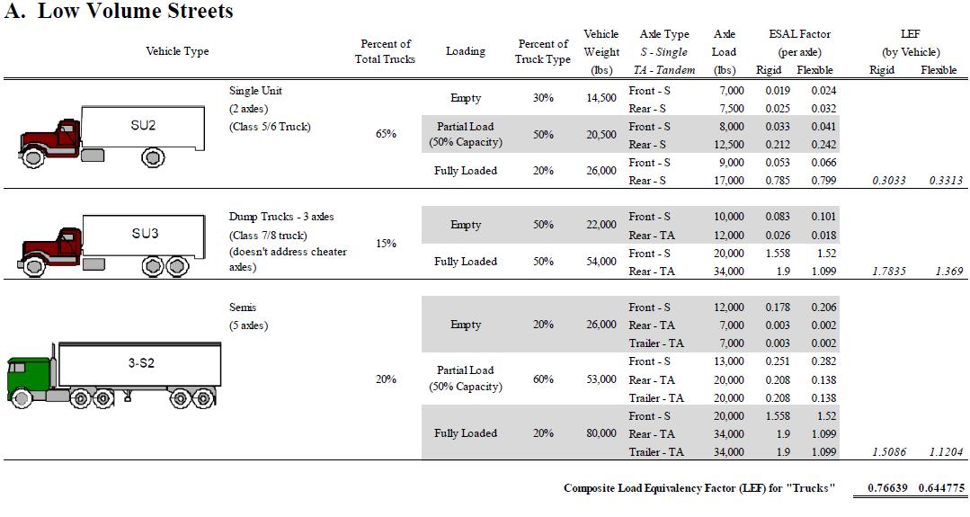
iv) Compute the growth factor from Equation 5.3-1 based on the average annual traffic growth rate and the analysis period.
v) Multiply the base year design lane ESALs, by the growth factor to obtain the total ESALs for the analysis period.
Equation 5.3-1
Growth Factor = [(1+r)n]-1/ nfor values of n > 0 when:
n = Design Period in years
r = Average Annual Traffic Growth Rate in percent.
Design Requirements Page | 5-10 9/25/2023 Design Criteria Manual
Table 5.3-6 - Low-Volume Truck Mixture for Urban Roadways and Determination of Truck ESAL Factor
Table 5.3-6 - Assumptions:
a) ESAL factors for individual axles were determined from AASHTO Design Guide.
b) Assumed an initial pavement thickness of 8 inches and SN of 3.25 (does not significantly impact ESAL factor - +/- 3%).
c) Assumed a terminal serviceability of 2.25.
d) ESAL factors do not account for directional split (i.e. if 2 lane roadways with total AADT and 50/50 directional split, divide ESAL factor in half.).
e) Vehicle weights and payload obtained from US Department of Energy Fact #621: Gross Vehicle Weight vs. Empty Vehicle Weight.
f) Assumed maximum single axle load of 20,000 pounds (including steering axle) and tandem axle load of 34,000 pounds.
g) Percent of fully loaded, partially loaded, and empty vehicles were estimated No supporting documentation.
Sources: 2010 Iowa DOT traffic count data (unless otherwise noted), Iowa SUDAS, Design Manual Chapter 5 - Roadway Design 5F - Pavement Thickness Design (2016)
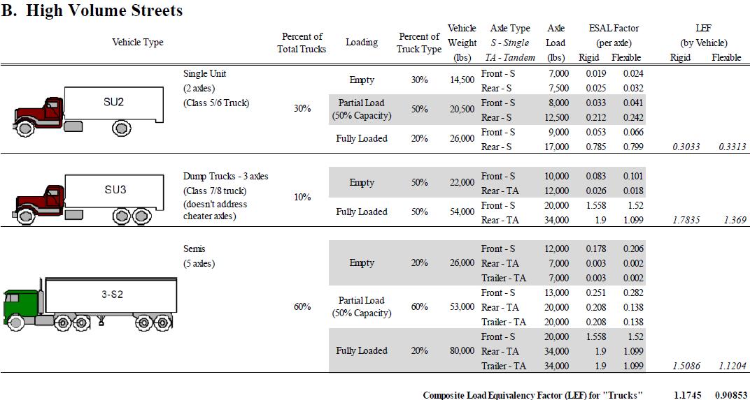
It should be noted that it is not the wheel load but rather the damage to the pavement caused by the wheel load that is of particular concern. As described above, the ESAL is the standard unit of pavement damage and represents the damage caused by a single 18,000-pound axle load.
Therefore, a two-axle vehicle with both axles loaded at 18,000 pounds would produce two ESALs. However, since vehicle configurations and axle loads vary, AASHTO has established a method to convert different axle loads and configurations to ESALs For example, a 34,000-pound tandem axle produces approximately 1.9 ESALs for rigid pavement (1.1 for flexible pavement) Summing the different ESAL values for each axle combination on a vehicle provides a vehicle’s Load Equivalency Factor (LEF) The LEF can then be applied to the assumed truck mix and the AADT to determine ESALs.
Design Requirements Page | 5-11 9/25/2023 Design Criteria Manual
FHWA Vehicle Category
Motorcycles - All two or three-wheeled motorized vehicles. Typical vehicles in this category have saddle type seats and are steered by handlebars rather than steering wheels. This category includes motorcycles, motor scooters, mopeds, motor-powered bicycles, and threewheel motorcycles.
Passenger Cars - All sedans, coupes, and station wagons manufactured primarily for the purpose of carrying passengers and including those passenger cars pulling recreational or other light trailers.
Other Two-Axle, Four-Tire Single Unit Vehicles - All two-axle, four-tire, vehicles, other than passenger cars. Included in this classification are pickups, panels, vans, and other vehicles such as campers, motor homes, ambulances, hearses, carryalls, and minibuses. Other twoaxle, four-tire single-unit vehicles pulling recreational or other light trailers are included in this classification. Because automatic vehicle classifiers have difficulty distinguishing class 3 from class 2, these two classes may be combined into class 2.
Buses - All vehicles manufactured as traditional passenger-carrying buses with two axles and six tires or three or more axles This category includes only traditional buses (including school buses) functioning as passenger-carrying vehicles Modified buses should be considered to be a truck and should be appropriately classified.
Truck Reporting Guidelines - In reporting information on trucks, the following criteria should be used:
• Truck tractor units traveling without a trailer will be considered single-unit trucks;
• A truck tractor unit pulling other such units in a saddle mount configuration will be considered one single-unit truck and will be defined only by the axles on the pulling unit;
• Vehicles are defined by the number of axles in contact with the road. Therefore, floating axles are counted only when in the down position; and
• The term "trailer" includes both semi- and full trailers.
Two-Axle, Six-Tire, Single-Unit Trucks - All vehicles on a single frame including trucks, camping and recreational vehicles, motor homes, etc., with two axles and dual rear wheels.
Three-Axle Single-Unit Trucks - All vehicles on a single frame including trucks, camping and recreational vehicles, motor homes, etc., with three axles.
Four or More Axle Single-Unit Trucks - All trucks on a single frame with four or more axles.
Four or Fewer Axle Single-Trailer Trucks - All vehicles with four or fewer axles consisting of two units, one of which is a tractor or straight truck power unit.
Five-Axle Single-Trailer Trucks - All five-axle vehicles consisting of two units, one of which is a tractor or straight truck power unit.
Design Requirements Page | 5-12 9/25/2023 Design Criteria Manual
Six or More Axle Single-Trailer Trucks - All vehicles with six or more axles consisting of two units, one of which is a tractor or straight truck power unit.
Five or Fewer Axle Multi-Trailer Trucks - All vehicles with five or fewer axles consisting of three or more units, one of which is a tractor or straight truck power unit.
Six-Axle Multi-Trailer Trucks - All six-axle vehicles consisting of three or more units, one of which is a tractor or straight truck power unit
Seven or More Axle Multi-Trailer Trucks - All vehicles with seven or more axles consisting of three or more units, one of which is a tractor or straight truck power unit.
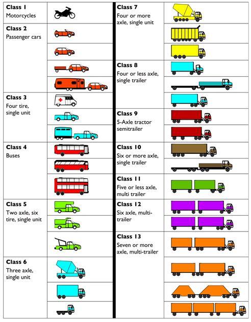
(Source: www.fhwa.dot.gov/policyinformation/tmguide/tmg_2013/vehicle-types.cfm)
Requirements Page | 5-13 9/25/2023
Criteria Manual
Design
Design
Figure 5.3-1 lists the 13 vehicle category classifications used by FHWA.
Figure 5.3-1 - FHWA 13 Vehicle Category Classification
Detailed steps are involved in ESAL calculations for both rigid and flexible pavements The need for separate ESAL values for flexible and rigid pavements is based on the inherent ability of each type of pavement to distribute a point loading Rigid pavements have the ability to distribute the load across the slab A point loading on a flexible pavement is more localized This results in different ESAL factorsforthe two types of pavements This is shown graphically in Figure 5.3-2
Flexible Pavement Point Loading Rigid Pavement Point Loading
3) Drainage Coefficient (CD) - The drainage coefficient characterizes the quality of drainage of the subbase layers under the concrete slab Good draining pavement structures do not give water the chance to saturate the base and subgrade; thus, pumping is not as likely to occur.
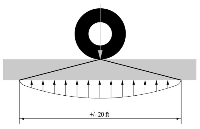
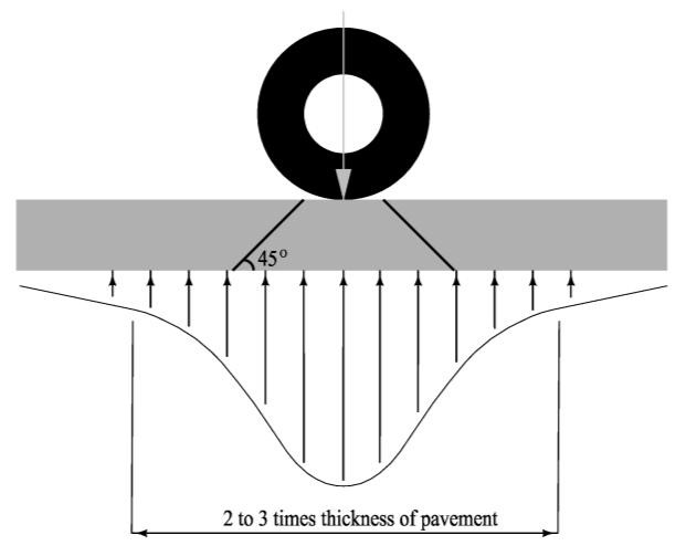
The AASHTO Guide provides a table of drainage coefficients based on the anticipated exposure of the pavement structure to moisture and on the quality of drainage of the base layers Higher drainage coefficients represent better drainage The most credit is given to permeable bases with edge drains.
DOT has not had much experience with positive drainage systems As stated earlier, DOT's philosophy on this issue is to prevent water intrusion and pumping by using bases that are dense graded, non-erosive, and stabilized. DOT has had good performance with such bases, and it is believed that the bases recommended earlier in this section provide performance equivalent to a fair level of drainage.
The following definitions are offered as a guide.
• Excellent Drainage: Material drained to 50% of saturation in 2 hours.
• Good Drainage: Material drained to 50% of saturation in 1 day.
• Fair Drainage: Material drained to 50% of saturation in 7 days.
• Poor Drainage: Material drained to 50% of saturation in 1 month.
Design Requirements Page | 5-14 9/25/2023 Design Criteria Manual
Figure 5.3-2 - Flexible and Rigid Pavement Point Loading
• Very Poor Drainage: Material does not drain.
Based on these definitions, the CD value for the road test conditions would be 1.00. A value of 1.00 would have no impact on pavement thickness or the number of ESALs a section would carry Lower values increase the required pavement thickness; higher values decrease the required pavement thickness Based on Tables 2.4 and 2.5 from the 1993 AASHTO Design Guide, the analysis assumed a poor quality of drainage and 5% to 25% exposure to saturation for the drainable base sections have a range of 0.80 to 0.60, respectively.
In 1993 ERES' evaluated that water present in the county's residential streets is drained out of the system very slowly (poor quality of drainage) and recommended the value of 0.80 If the engineer decides to use a different value, then it must be documented and justified
4) Reliability, R% - Reliability is the probability that the design will succeed for the life of the pavement Because higher roadway classification facilities are considered more critical to the transportation network, a higher reliability is used for these facilities The R% listed in Table 5.3-7 shall be used If the engineer decides to use a different value, then it must be documented and justified.
Design Requirements Page | 5-15 9/25/2023 Design Criteria Manual
Table 5.3-7 - Reliability (R%) for Flexible and Rigid Pavement Design
5) Overall Standard Deviation (S0) - Overall standard deviation accounts for both chance variation in the traffic prediction and normal variation in pavement performance prediction for a given traffic The AASHTO Guide recommends values in the range of 0.40 to 0.50, with 0.45 being the overall standard deviation from the AASHO Road Test. Higher values represent more variability; thus, the pavement thickness increases with higher overall standard deviations. The 0.45 value at the mid-range is considered reasonable (ERES, 1993) for and is to be used for flexible pavement design.
6) Soil Resilient Modulus (MR) - The important variable in describing the foundation for pavement design is the Soil Resilient Modulus (MR) MR is a property of the soil that indicates the stiffness or elasticity of the soil under dynamic loading.
The Soil Resilient Modulus measures the amount of recoverable deformation at any stress level for a dynamically loaded test specimen The environment can affect pavement performance in several ways Temperature and moisture changes can have an effect on the strength, durability, and load-carrying capacity of the pavement and roadbed materials Another major environmental impact is the direct effect roadbed swelling, pavement blowups, frost heave, disintegration, etc. can have on loss of riding quality and serviceability If any of these environmental effects have the potential to be present during the life cycle of the pavement, the MR should be evaluated on a season-by-season basis, and a seasonal modulus developed.
The purpose of using seasonal modulus is to qualify the relative damage a pavement is subject to during each season of the year and treat it as part of the overall design. An effective soil modulus is then established for the entire year, which is equivalent to the combined effects of all monthly seasonal modulus values.
For the purposes of this section, the MR value was calculated based on the proposed CBR values of 3, 6, and 10. The normal soils in St. Louis County have in situ CBR values of 1 to 3. In order to successfully develop a foundation CBR of 10, it is most likely going to involve use of a subgrade that is stabilized with cement, fly ash, or other products. NCHRP Project 1-28 provides a relationship between CBR value and MR value (see equation below). Using this equation, the corresponding MR values for CBR values of 3, 6, and 10 are shown in Table 5.3-8. The CBR value of 3 has been selected as the default design value. If the engineer decides to use a different value, then it must be documented and justified.
Design Requirements Page | 5-16 9/25/2023 Design Criteria Manual
Street Classification Reliability, percent Residential Streets 85 Collector Streets 90 Arterial Streets (Major and Minor) 95
7) Layer Coefficients - Structural layer coefficients (ai values) are required for flexible pavement structural design. A value for these coefficients is assigned to each layer material in the pavement structure in order to convert actual layer thickness into the structural number (SN) These historical values have been used in the structural calculations If specific elements, such as a Superpave mix or polymer modified mix are used, the designer should adjust these values to reflect differing quality of materials The following table shows typical values for layer coefficients.
Design Requirements Page | 5-17 9/25/2023 Design Criteria Manual
between CBR and MR values per NCHRP Project 1-28: ����=1941.488 �������� 0.6844709 Table 5.3-8 CBR Value MR Value 3 4120 6 6620 10 9390
Relationship
Component Coefficient (ai) Surface Course: SP125 (PG76-22 or PG64-22V))CLP 0.48 SP125 (PG70-22 or PG64-22H)DLP 0.46 Type C Bituminous Pavement 0.44 Base Course: SP 190 (PG70-22 or PG64-22H)DLP 0.42 Type X Bituminous Pavement 0.40 Asphalt Treated Base Class I 0.34* Bituminous Treated Aggregate Base 0.23 Asphalt Treated Base Class II 0.26 Cold-Laid Bituminous Concrete Base 0.23 Cement Treated Granular (Aggregate) Base 0.20* Soil-Cement Base 0.15 Type 5 Aggregate Base 0.14* Macadam Stone Base 0.12 PCC Base (New) 0.50 Old PCC 0.40** Crack and Seated PCC 0.25 to 0.30 Rubblized PCC 0.24 Cold-in-Place Recycled Asphalt Pavement 0.22 to 0.27
Table 5.3-9 - Layer Coefficients
Notes:
* Indicates coefficients taken from AASHTO Interim Guide for the Design of Flexible Pavement Structures.
** This value is for reasonably sound existing concrete Actual value used may be lower, depending on the amount of deterioration that has occurred.
Source: AASHTO, Kansas State University, and Iowa DOT
5.3.6 Mechanical Subgrade Modification
Geogrids - Geogrids are a regular network of tensile elements with apertures of sufficient size to interlock surrounding fill material Multiaxial geogrids are used in aggregate base courses and have strength in two or more direction. Particles in the aggregate base course may move due to traffic loading causing surface rutting Multiaxial geogrids are beneficial to use when traffic stresses exceed the aggregate base course lateral restraint capacity causing rutting and alligator cracking in hot mix asphalt pavement.
The geogrid shall not have any distortions or waves in the lay down. For maximum benefit, the geogrid should be installed a minimum of 4 inches but not more than 12 inches beneath the top of the aggregate base. Geogrid shall be installed in the aggregate base and not in the soil subgrade. The aggregate base material gradation is extremely important because aggregate particles need to interlock in the aperture openings of the specified multiaxial geogrid. An aperture dimension range from 0.5 to 1.5 times the nominal maximum size of the aggregate gradation tends to interlock well.
Construction experience has shown that placing 4 to 8 inches of compacted aggregate base on the geogrid should allow for an adequate construction platform. However, the engineer should check each design to ensure a stable platform for construction equipment. Aggregate material should initially be placed in the center of the geogrid and then spread outward radially in a uniform depth to the geogrid edges Tracked equipment shall not be allowed to drive directly on the geogrid itself The engineer should consult with the manufacturer and comply with their design and construction guidelines There would be a job special provision created and inserted in the contract documents.
5.3.7 Staged Construction - For staged construction, construction shall consist of aggregate base course and full plan thickness of the hot mix asphalt base. Before final wearing course is placed, include tack (SS-1h) and a 1-inch thick wedge course using SP 095 with the same binder grade and traffic level as the wearing course The engineer shall include a note to this affect in the contract documents and include the appropriate quantities.
Design Requirements Page | 5-18 9/25/2023 Design Criteria Manual Full Depth Reclamation 0.18 Subbase Course: Soil-Cement Subbase (10% cement) 0.10 Soil-Lime Subbase (10% lime) 0.10 Modified Subbase 0.14 Soil-Aggregate Subbase 0.05*
5.3.8 Tack Application Rates
5.3.8.2 Tack - For overlay or full-depth hot mix asphalt construction tack is applied to the horizontal and vertical surfaces that the mix is being applied against. The type of tack is typically an emulsion Tack can be a PG graded binder, as applied when bonded geosynthetic material to an existing concrete or asphalt surface. Tack is incidental to the installation of geosynthetic fabrics In all other cases tack is applied as an emulsion between each lift of hot mix asphalt. Field application rates can vary from 0.05 to 0.15 gallons per square yard for Superpave and Bituminous hot mix overlays For estimating purposes use the following application rates for the following mix types and pavement conditions:
5.3.9 Asphalt Binder - Performance grade (PG) asphalt binders are identified by their desired "high temperature" (e.g. "64", "70", "76", etc.) and "low temperature" (e.g. "-22", "-28", "-34", etc.) characteristics. The temperature numbers represent Celsius degrees and are used in 6-degree increments. The high temperature value is associated with controlling rutting, while the low temperature value is associated with resisting cold weather cracking. Table 5.3-10 & 5.3-11 should be used as a guide to select asphalt binder grades for bituminous mixtures.
MSCR Binder Identification. In lieu of AASHTO M 320, Table 2, AASHTO M 332, Table 1 may be substituted, eliminating the elastic recovery requirement. The equivalent grading will PG 64-22 (see table below), Grade S for PG 64-22, PG 64-22 Grade H for PG 70-22 and PG 64-22 Grade V or E for PG 76-22. Specialty grades will be tested at the grade temperature for the desired characteristics, i.e. PG 58-28 for RAP/RAS mixtures. Binder grade may be changed by the Engineer and be paid for in accordance with Section 109. Production binder materials shall not be "air-blown or acid modified" to achieve the performance grade. Binders with fibers or other discrete particles larger than No. 60 sieve are not allowed. Specialty grades will be tested at the grade temperature for the desired characteristics in accordance with Section 413. The contractor shall indicate the MSCR binder grade on their mix design submittal. Suppliers shall furnish binder technical data with the Contractor's job mix design. The traffic grades of asphalt binder shall conform to the tables below for PG 64-22, PG 5822, or AASHTO M 332 - Table 1.
Departmental approval is required for loading designation selection of all Superpave Asphaltic Concrete pavements. Binder grade requirements shall be provided by the department upon request.
Design Requirements Page | 5-19 9/25/2023 Design Criteria Manual
Existing Pavement Condition Application Rate (gallons/sy) New Asphalt 0.06 Oxidized Asphalt 0.08 Milled Surface 0.11 Portland Cement Concrete 0.07
5.3.10 Mix Selection - Table 5.3-10 should be used as a guide in selecting the appropriate asphalt mix. Tables 5.3-13A and 5.3-13B should be used as a guide for identification of the mix by pay item number and by description. See "Pavement Thickness Requirements" for additional mix selection discussion regarding minor road spot improvements. Specifying Superpave requires:
• Mix Type.
• Binder Type and designation.
• Traffic Level.
• Skid Resistance designation.
For skid resistance on Arterial Roads an LP, Limestone/Porphyry designation is standard with SP 125 or SP 95 wearing courses (i.e. SP 125 (PG70-22)CLP). An LS, Limestone/Slag designation is available when suppliers decide that it is economically viable.
Table 5.3-12 should be used as a guide in determination of Traffic Level assignment in the absence of Equivalent Single Axle Load (ESAL) values.
* Note: Binder may be bumped up one or two levels if truck traffic type and movement requires
Design Requirements Page | 5-20 9/25/2023
Criteria Manual
Design
Type of Corridor Traffic Level Type of Mix Asphalt Binder Skid Resistance Arterial Roads B & C Wearing Course SP 125 PG70-22 or PG64-22H* LP or LS Base Course SP 190 PG64-22 or PG64-22S* None Arterial Roads D Wearing Course SP 125 PG64-22 or PG64-22S* LP or LS Base Course SP 190 PG 64-22 or PG64-22S * None Collector Roads C, D E, F Wearing Course SP 125 PG 64-22 or PG64-22S * None Base Course SP 190 PG 64-22 or PG64-22S None Local Roads Residential & Non-Residential E & F Wearing Course Type "C" PG 64-22 or PG64-22S None Base Course Type "X" PG 64-22 or PG64-22S None Drive Approaches and Parking Lots F Wearing Course Type "D" Bituminous Pavement or SP 95 PG 64-22 or PG64-22S None Base Course Type "X" Bituminous Pavement or SP 190 PG 64-22 or PG64-22S None
Table 5.3-10 - Asphalt Binder Selection Criteria
Table 2 summarizes the Design Traffic Level and binder classification adjustments for the wearing course depending on traffic conditions.
Use of any other PG asphalt binder must be approved by the St Louis County Chief Materials Engineer.
The use of recycled materials (Reclaimed Asphaltic Pavement and/or Reclaimed Asphaltic Shingles) is allowed by the material manufacturer in accordance with Section 413 of the St. Louis County "Standard Specifications for Road and Bridge Construction" manual and is not required to be specified.
Standing: For extremely slow traffic of less than 12 mph (Metro bus stops, Stop sign or signal-controlled intersections).
Slow: When traffic speeds are expected to be in the range of 12 to 45 mph or for traffic levels above 10,000,000 ESALs
Standard: The base binder for the traffic ESAL’s or Class as per Table 3 when Slow or Standing traffic is not to be encountered.
Requirements Page | 5-21 9/25/2023
Criteria Manual
Design
Design
Design Level Standing Slow Standard F PG64-22 or PG64-22S PG64-22 or PG64-22S PG64-22 or PG64-22S E PG70-22 or PG64-22H PG64-22 or PG64-22S PG64-22 or PG64-22S D PG76-22 or PG64-22V PG70-22 or PG64-22H PG64-22 or PG64-22S C PG76-22 or PG64-22V PG70-22 or PG64-22H PG70-22 or PG64-22H B PG76-22 or PG64-22V PG70-22 or PG64-22H PG70-22 or PG64-22H
Table 5.3-11 - Adjustment to Wearing Course Binder PG Grade
Table 5.3-12 - Superpave Design Applications
F ≤ 300,000
Applications include roadways with very light traffic; volumes such as local roads, country roads, and city streets where truck traffic is prohibited or at a very minimal level. Traffic on these roadways would be considered local in nature, not regional, intrastate, or interstate. Special purpose roadways serving recreational sites or areas may also be applicable to this level. Typically used on non-collector CRS roadways.
E ≤ 3,000,000
Applications include many collector roads or access streets. Medium-trafficked city streets and the majority of country roadways may be applicable to this level. Typically used on CRS collectors
D ≤ 10,000,000
Applications include medium-traveled two-lane, multilane, and divided collector roads and access streets. Typically used on ARS roadways.
C ≤ 30,000,000
Applications include heavy-traveled two-lane, multilane, and divided collector roads and access streets. Typically used on ARS roadways within zones with moderate commercial use. (Hanley and Brentwood are two examples). Also applicable for many state routes, US highways and some rural interstates.
B > 30,000,000
Applications include heavy-traveled two-lane, multilane, and divided collector roads and access streets. Typically used on ARS roadways within zones with heavy commercial use. Also applicable for majority of interstate routes and truck climbing lanes.
Requirements Page | 5-22 9/25/2023
Criteria Manual
Design
Design
Design Level Design Traffic (ESALs)
Typical Roadway Applications
construction on CRS roads, detours, temporary pavements, new subdivisions, all shoulders
Design Requirements Page | 5-23 9/25/2023 Design Criteria Manual
Bid Tab Information Application Information Mix Design Information Item No. Description Applications Non-Skid Required Design Information Mix Design Binder "Low" Type Mixes (Bituminous Pavements) - 405 Items 405-30.10 Type
Bituminous Pavement Overlay and
of
No Minimum compacted lift thickness: 1.5 inches 50 Blow Marshall or 50 gyrations of Gyratory Compactor PG64-22 PG64-22S 405-30.20 Type D Bituminous Pavement
No Minimum compacted Lift Thickness: 1 inch 50 Blow Marshall or 50 gyrations of Gyratory compactor PG64-22 PG64-22S 405-30.30 Type
Bituminous Pavement Base
No Minimum compacted lift thickness:
50 Blow Marshall or 50 gyrations of Gyratory compactor PG64-22 PG64-22S
Table 5.3-13A - St. Louis County Bituminous Pavement Mixes
C
construction
CRS roads, detours, temporary pavements, new subdivisions, all shoulders
Drive Approaches and Parking Lots
X
2 inches
Design Requirements Page | 5-24 9/25/2023 Design Criteria Manual
404-09.XX Superpave Asphaltic Concrete Mixture SP 95 (x)y /LP / LS
x= PG Binder Grade; y= Design Level LP= LimestonePorphyry LS= LimestoneSlag
ARS & CRS Roads.
Structural Overlays where complete joint and base repairs have been made. New fulldepth construction at least 10' wide.
Modified Binders (PG 70-22, 76-22) to only be used where the configuration will permit over 500 tons of production at a time.
Minimum compacted lift thickness: 1 inch. ESALs over Design Life are required to determine aggregate properties and design gyrations. (All Levels)
Compactor
x= PG Binder Grade; y= Design Level LP= LimestonePorphyry LS= LimestoneSlag
ARS Roads only
Structural Overlays where complete joint and base repairs have been made. New fulldepth construction at least 10' wide. Modified Binders (PG 70-22, 76-22) to only be used where the configuration will permit over 500 tons of production at a time.
Gyratory Compactor
PG70-22 PG64-22
Yes (LP & LS mixes only) PG76-22
Design Requirements Page | 5-25 9/25/2023 Design Criteria Manual
Bid Tab Information Application Information Mix Design Information Item No. Description Applications NonSkid Required Design Information Mix Design Binder Superpave Mixes (Asphaltic Concretes) – 404 Items
Table 5.3-13B - St. Louis County Bituminous Pavement Mixes
Gyratory
Yes (LP & LS mixes only) PG76-22 PG70-22 PG64-22
404-12.XX Superpave Asphaltic Concrete Mixture SP125 (x)y /LP / LS
Minimum compacted lift thickness: 1.5 inches. ESALs over Design Life are required to determine aggregate properties and design gyrations. (Levels B-D only)
Table 5.3-13B - St. Louis County Bituminous Pavement Mixes (Continued)
404-12.XX Superpave Asphaltic Concrete Mixture SP125 (x)y/LP/LS
x= PG Binder Grade; y= Design Level LP= LimestonePorphyry LS= LimestoneSlag
CRS Roads only. New full-depth construction at least 10' wide. PG64-22 binder specified unless special traffic loadings require modification. Modified Binders (PG 70-22) to only be used under special loading conditions and where the configuration will permit over 500 tons of production at a time. [LP & LS designation not typically required, unless non-skid required]
No (Yes, if LP & LS mixes only)
Minimum compacted lift thickness: 1.5 inches. ESALs over Design Life are required to determine aggregate properties and design gyrations. (Level E-F only)
Gyratory Compactor PG70-22 PG64-22
404-19.XX Superpave Asphaltic Concrete Mixture SP190 (x)y
x= PG Binder Grade y= Design Level Not appropriate for base repairs.
ARS & CRS Roads. New full-depth construction at least 10' wide. PG64-22 binder specified unless traffic loadings indicate modification is required. Modified Binder (PG 70-22,) to only be used under special traffic loading conditions and where the configuration will permit over 500 tons of production at a time.
No Minimum compacted lift thickness: 2.25 inches. ESALs over Design Life are required to determine aggregate properties and design gyrations. (All Traffic Levels)
Gyratory Compactor PG70-22 PG64-22
Design Requirements Page | 5-26 9/25/2023 Design Criteria Manual Bid Tab Information Application Information
Design Information Item No. Description Applications NonSkid Required Design Information Mix Design Binder Superpave Mixes (Asphaltic Concretes) – 404 Items
Mix
5.4 Concrete Pavement Design
5.4.1 Rigid Pavement Types - Different pavement types use different types of joints and reinforcement to control the forces acting on the concrete pavement These forces include curing shrinkage of the concrete, environment changes and traffic loads Forces in the concrete pavement will cause cracks to form without traffic.
The designer can select the location where the joints will be placed and, consequently, where the cracks will form Joints may be thought of as “controlled cracks” that will reduce the stresses the concrete will experience during its life and greatly increase the life of the concrete pavement Through the use of reinforcement, the location and spacing of cracks can also be controlled.
The type of concrete pavement commonly used in St. Louis County is jointed concrete pavement (JCP).
5.4.1.1 Jointed Concrete Pavement (JCP) - JCP has transverse joints spaced at regular intervals The transverse joints are used to control temperature induced contraction and expansion in the concrete Smooth, epoxy-coated, steel dowel bars are used at the transverse joints for load transfer The transverse joints are spaced at a maximum of 15 feet.
Longitudinal joints are used to control random longitudinal cracking. Longitudinal joints are tied together with deformed, epoxy-coated, steel tie bars.
The thickness design of JCP is detailed in Section 5.4.2, "Approved Design Method" and Section 5.4.3, "Rigid Pavement Design Process". Other JCP details are governed by the concrete pavement joint design (Drawing C502.13 Joints) standards that can be obtained from St. Louis County Department of Transportation internet web site.
5.4.2 Approved Design Method - AASHTO Rigid Pavement Design Procedure.
The 1993 AASHTO "Guide for Design of Pavement Structures" is the only approved design method for rigid pavements for St. Louis County DOT. This design procedure is available in automated form Automated procedures include the American Concrete Pavement Association (ACPA) StreetPave™ program. The program is available at: www.acpa.org/streetpave
StreetPave 12™ is the latest in jointed plain concrete pavement thickness design StreetPave is a mechanistic/empirical procedure based on computed stresses, strains, and deflections and empirical performance observations This software is able to perform jointed plain concrete overlay designs for all six types (bonded on asphalt, unbonded on asphalt, unbonded on concrete, bonded on composite, unbonded on composite). For existing concrete pavements and overlays, StreetPave 12 may be used to estimate service life and/or failure criteria.
If you have any direct questions about the software, feel free to contact Robert Rodden, ACPA's Director of Technical Service and Product Development at rrodden@acpa.org
Design Requirements Page | 5-27 9/25/2023 Design Criteria Manual
The program is available to St. Louis County DOT personnel through the Construction Division's chief materials engineer Consultants may obtain the program online from the ACPA.
The AASHTO Guide also contains design procedures for rehabilitation of rigid pavements, including asphalt concrete overlays or Portland cement concrete (PCC) overlays of existing rigid pavements Contact the chief materials engineer for further assistance.
5.4.3 Rigid Pavement Design Process - New rigid pavement design requires several properties to determine the minimum required pavement thickness. The following parameters will be discussed in Section 5.4.4 and input values have been selected:
• 28-day Concrete Modulus of Rupture, Mr (equal to Sc in AASHTO), psi.
• 28-day Concrete Elastic Modulus (E), psi
• Effective Modulus of Subbase/Subgrade Reaction (k), psi/in
• Serviceability indices.
• Load Transfer Coefficient
• Drainage Coefficient
• Overall Standard Deviation.
• Reliability, %
• Percent cracked slabs at end of service life.
• Traffic category (residential, collector, minor arterial, major arterial, and user-defined)
• Design lanes & directional distribution
• Average Daily Truck Traffic (ADTT) or Average Daily Traffic (ADT) with % trucks
• Traffic growth
5.4.3.1 Other Features - StreetPave™ has the ability to design concrete overlays. This is considered a surface treatment and is not covered in this section.
5.4.3.2 StreetPave™ Software Design Example: This Section Intentionally Blank
Design Requirements Page | 5-28 9/25/2023 Design Criteria Manual
5.4.4 Recommended Input Design Values - St. Louis County, Missouri is located geographically in an area subjected to high wet freeze-thaw cycles Concrete properties have been specified to account for these harsh climatic conditions.
Input Values:
5.4.4.1 28-day Concrete Modulus of Rupture, S’C - The S’C of concrete is a measure of the flexural strength of the concrete as determined by breaking concrete beam test specimens For S’C = 2.3*f’c (2/3) (see ACI 330) and 28-day compressive strength (f’c) of 4,500 psi, a S’C of 620 psi at 28 days should be used with the current specification for concrete pavement design. If the engineer selects an alternate value for S’C, it must be documented with an explanation.
5.4.4.2 28-day Concrete Elastic Modulus (EC) - Elastic modulus of concrete is an indication of concrete stiffness It varies depending on the coarse aggregate type used in the concrete Although the value selected for pavement design could be different from the actual values, the elastic modulus does not have a significant effect on the computed slab thickness EC is equivalent to 5,700 x S’C for a modulus of 3,420,000 psi should be used for pavement design The use of a different value must be documented with an explanation.
5.4.4.3 Effective Modulus of Subgrade Reaction: k-value - The AASHTO guide allows pavement designers to consider the structural benefits of all layers under the concrete slab. The guide also allows designers to consider the effect of loss of support of the underlying material due to erosion or deterioration. The slab support is characterized by the modulus of subgrade reaction, otherwise known as k-value.
Field performance evaluations of concrete pavement have revealed that the soundness of the subbase and base is essential to the long-term performance of concrete pavement If the subbase and base underneath the concrete slab does not provide good support, long-term pavement performance will be severelycompromised regardless of the concrete slab thickness.
In accordance with the ASTM Soil Classification system (ASTM D 2487), most soils in St. Louis county can be classified as CL, ML, CL-ML, or CH. Soils of this classification primarily consist of inorganic clays and silts (fine-grained soils) with low to high plasticity and low to high shrink-swell potential. According to AASHTO these soils have a general rating as a subgrade of fair to poor. CBR testing has been performed, which resulted in an average value of 4 percent. To achieve minimal rutting damage of the finished subgrade and achieve proper placement and compaction of overlying pavement layers, the in-situ subgrade CBR shall be at least 6 percent in the top 12 in. of subgrade at the time of pavement construction (ERES, 1993). To determine that this has been achieved the use of a Dynamic cone Penetrometer (DCP) is recommended. In some cases, soil modification may be required to achieve this bearing capacity.
For soil subbase the mean value of keff used shall be 50 psi/in.
A k-value of 100 psi/in. should be used in the rigid pavement design procedure with the base layer listed above.
Design Requirements Page | 5-29 9/25/2023 Design Criteria Manual
5.4.4.3.1
DOT-Required Minimum Subbase Layer
• 4 inches Type 5 Aggregate Subbase
DOT-Optional Base Layer Combinations - DOT recognized the optional use of one of the following base layer combinations for concrete slab support:
5.4.4.3.2
• 4 inches of Type X Bituminous concrete base; or
• A minimum 1-inch SP 095 (PG64-22)D asphaltic concrete bond breaker over 6 inches of a cement stabilized base.
A k-value of 300 psi/in. should be used in the rigid pavement design procedure with one of the stabilized base layer combinations listed above.
The designer may use a higher k-value, up to 800 psi/in., with the requirement of field verification tests during the construction. Conduct verification tests in accordance with "Method 1: On-site Static Load Test" found in Tex 125-E, "Determining Modulus of Subgrade Reaction (k-value)".
Use a 30-inch diameter steel plate and test on top of the base for every 0.1 mile of roadbed, for each 20 feet of plan dimensional steel plate width or a portion of that. The kvalues obtained from verification tests may be adjusted by the loss of support factor as directed by the Engineer. These k-values should meet the design k-value at all times during construction.
The DOT recognizes the use of stabilized bases because they do not erode over time under truck traffic loading The DOT's general philosophy is to prevent water intrusion and pumping of underlying materials by using bases that are dense graded, non-erosive, and stabilized Bases that are properly designed and constructed using DOT specifications and test methods should provide adequate long-term support.
Where long-term moisture susceptibility of Type "X" Bituminous base is a concern, using a plan note to increase the target laboratory density (and thus total asphalt content) may be beneficial To ensure long-term strength and stability of cement stabilized layers, sufficient cement must be used in the mixture The use of this will require a job special provision, which should be included in the contract documents.
Selecting Appropriate Strength - There are several approaches to selecting an appropriate strength (and, indirectly, cement content as a result):
• Successful long-term experience with similar materials.
• Laboratory testing using 100% of the retained strength of a conditioned specimen to determine if the design cement content and strength are acceptable.
• Laboratory testing using the tube suction test to determine if the design cement content and strength are acceptable.
Design Requirements Page | 5-30 9/25/2023 Design Criteria Manual
Use of Bond Breaker - A bond breaker should always be used between concrete pavement and cement stabilized base There have been several instances in other jurisdictions where excessive cracking and premature failures occurred when a concrete slab was placed directly on cement stabilized base These problems occur because concrete slabs tend to bond directly to cement stabilized bases This increases the chances for cracks in the base to reflect through the overlying slab This also increases tensile stresses in the concrete slab due to temperature and moisture changes, resulting in higher chances of additional cracking.
The DOT requires a minimum of 1-inch asphalt concrete stress-relieving layer be used between cement stabilized base and the concrete slab. A polyethylene sheet is not recommended for use as a bond breaker, due to construction problems evident from experience in other states.
The subgrade is usually stabilized or treated with lime or cement to facilitate construction as well as to provide additional support to the pavement structure. Large volume changes in the subgrade resulting from moisture variations or other causes can cause the deterioration of concrete pavement. These volume changes in the subgrade should be minimized by appropriate means. Contact the Construction Division, Materials and Research Section for further assistance, if needed.
5.4.4.4 Subgrade/Base Widths - For formed concrete pavement the subbase should be designed 1 foot wider than the concrete slab on each side to accommodate formwork. For slip-formed (machine placed) concrete pavement, the subbase should be designed 3 feet wider than the concrete slab on each side to accommodate slipform pavement equipment tracks.
5.4.4.5 Performance Criteria (Serviceability Indexes) - Condition of pavements are rated with a present serviceability index (PSI) ranging from 5 (perfect condition) to 0 (impossible to travel).
5.4.4.5.1 Terminal Serviceability (Pt) - For concrete pavement design, the difference between the initial and terminal serviceability is an important factor An initial serviceability (P0) value of 4.5 is used in accordance with the AASHTO 1993 Design Guide (4.0 ERES, 1993) and a terminal serviceability (Pt) value in accordance with Table 5.4.3 - 1 (2.0 ERES, 1993) are to be used in the procedure Different values, if used, must be documented and justified.
Table 5.4.3-1 - Terminal Serviceability Indexes (Pt) for Street Classifications (AASHTO 1993 Design Guide)
2.00 Secondary Roads and Local Residential Streets
2.25 Minor Collectors, Industrial, and Commercial Streets
2.50 Major Collectors and Arterials
Design Requirements Page | 5-31 9/25/2023 Design Criteria Manual
t
P
Classification
5.4.4.5.2 Serviceability Loss (ΔPSI) - The predicted loss or drop in serviceability (ΔPSI) is the difference between initial and terminal serviceability (Po - Pt). The ΔPSI is the basis for the pavement design.
Table 5.4.3-1 - Terminal Serviceability Loss (ΔPSI) for Street Classifications (AASHTO 1993 Design Guide)
ΔPSI Classification
2.5 Secondary Roads and Local Residential Streets
2.25 Minor Collectors, Industrial, and Commercial Streets
2.0 Major Collectors and Arterials
5.4.4.6 Load Transfer Coefficient - The load transfer coefficient is used to incorporate the effect of dowels, reinforcing steel, tied shoulders, and tied curb and gutter on reducing the stress in the concrete slab due to traffic loading The coefficients recommended in the AASHTO Guide were based on findings from the AASHO Road Test. Table 5.4.4-1 lists the load transfer coefficient values to be used for rigid pavement design:
Table
5.4.4-1 - Load Transfer Coefficients
There is substantial evidence that tied Portland cement concrete (PCC) shoulders improve PCC pavement performance significantly Therefore, it is strongly recommended that tied PCC shoulders be provided, if possible In case it is not feasible to provide tied PCC shoulders, the use of a minimum 3-foot wider outside lane should be considered.
PCC shoulders should be tied to the main lane pavement by tie bars or by the main lane's transverse steel The joint between the concrete shoulder and the concrete main lane pavement should be a warping or hinge joint, not a construction or expansion joint The PCC shoulder should have the same thickness and the same base layers as the main lane pavement This will allow traffic to be routed on the shoulder during future maintenance and construction while reducing the chances of structurally damaging the shoulder It will also facilitate the construction sequence in most cases.
Design Requirements Page | 5-32 9/25/2023 Design Criteria Manual
Load Transfer Devices at Transverse Joints Tied PCC Shoulders, Curb and Gutter, or Greater Than Two Lanes in One Direction Yes No Yes 2.9 3.6 No 3.6 4.2
Tied or monolithic curb and gutter help in reducing edge stresses and serve as a barrier that discourages traffic from riding too close to the edge of the pavement structure Although tied curb and gutter sections usually contain tie bars, the tie bars are too small in either size or number to transfer load stresses effectively by themselves Construction joints usually exist between tied curb and gutter and the concrete pavement This means no aggregate interlock exists Since the number of edge stresses in the pavement are much less for monolithic curb sections than for tied curb and gutter sections, the use of monolithic curb is recommended when practical.
5.4.4.7 Drainage Coefficient (CD) - The drainage coefficient characterizes the quality of drainage of the subbase layers under the concrete slab. Good draining pavement structures do not give water the chance to saturate the base and subgrade; thus, pumping is not as likely to occur.
The AASHTO Guide provides a table of drainage coefficients based on the anticipated exposure of the pavement structure to moisture and on the quality of drainage of the base layers. Higher drainage coefficients represent better drainage. The most credit is given to permeable bases with edge drains.
DOT has not had much experience with positive drainage systems. As stated earlier, DOT's philosophy on this issue is to prevent water intrusion and pumping by using bases that are dense graded, non-erosive, and stabilized. DOT has had good performance with such bases, and it is believed that the bases recommended earlier in this section provide performance equivalent to a fair level of drainage.
In 1993 ERES' evaluated that water present in the county's residential streets is drained out of the system very slowly (poor quality of drainage) and recommended the value of 0.80 If the engineer selects another value supporting documentation is required for review and approval.
5.4.4.8 Overall Standard Deviation (S0) - Overall standard deviation accounts for both chance variation in the traffic prediction and normal variation in pavement performance prediction for a given traffic The AASHTO Guide recommends values in the range of 0.30 to 0.40, with 0.35 being the overall standard deviation from the AASHO Road Test. Higher values represent more variability; thus, the pavement thickness increases with higher overall standard deviations The 0.35 value at the mid- range is considered reasonable (ERES, 1993) for and is to be used for rigid pavement design.
5.4.4.9 Reliability, R% - The reliability value represents a "safety factor" with higher reliabilities representing pavement structures with less chance of failure The AASHTO Guide recommends values ranging from 50% to 80%, for local roadways Previously the DOT used values of 80 percent for local streets (CRS) and 85 percent for collector streets were chosen to improve the long-term pavement performance, which has failed to be proven The R% listed in Table 5.4.4-2 shall be used If the engineer decides to use a different value, then it must be documented and justified.
Design Requirements Page | 5-33 9/25/2023 Design Criteria Manual
5.4.4.10 Design Traffic 18-kip ESAL - The AASHTO Guide requires a prediction of the number of 18-kip ESALs that the pavement will experience over its design life.
The traffic projections for a highway project (in terms of ADT and one-way total 18-kip ESALs) are obtained from the traffic analysis report provided by the Planning or Operations Divisions This report is requested during the design phase of a project and, upon receipt, should be evaluated for reasonableness.
The predicted 18-kip ESALs is multiplied by a lane distribution factor (LDF) as shown in Table 5.4.4-2 This factor represents the percentage of the total one-way 18-kip ESALs that could be expected in the design lane The design lane is the lane that will carry the most traffic Usually, it is assumed that the outer lane of a highway with two lanes in each direction carries the most traffic For a three-lane facility, the middle lane is assumed to carry the most traffic Traffic distribution in urban areas is somewhat more complex due to merging and exiting operations, but the same assumptions could apply.
* Unless field observations show otherwise
The lane distribution factor (LDF) decreases with an increase in the number of lanes of a facility Highways with two lanes in each direction would have a higher LDF than highways with three or more lanes in each direction This is because traffic tends to spread out over the available lanes If there is a legal constraint requiring the trucks to use a particular lane, or avoid using certain lanes, then a review should be made of the appropriate lane distribution factor.
Design Requirements Page | 5-34 9/25/2023 Design Criteria Manual
Street Classification Reliability, percent Local Streets 85 Collector Streets 90 Arterial Streets 95
Table 5.4.4-2 - Reliability (R%) for Flexible and Rigid Pavement Design
Total Number of Lanes in Both Directions LDF ≤ 4 1.0 6 0.7 ≥ 8* 0.6
Table 5.4.4-2 - Lane Distribution Factor
The traffic analysis report (TAR) also lists a directional distribution of traffic This value indicates the percent distribution of the design hourly volume in each direction of a highway facility This value is used for capacity analysis and applies to all vehicles in the design hourly volume.
TAR assumes the directional distribution of heavy vehicles on any project is evenly split in both directions, unless specifically stated otherwise Typically, the directional distribution shown on the traffic projections from TAR applies only to the 30th highest hourly volume Therefore, the directional distribution factor listed in the TAR report should not be used to modify the design 18-kip ESALs
Local conditions may cause the directional distribution of heavy vehicles to be unequal. For example, locations near a major quarry adjacent to a highway with otherwise modest levels of truck traffic. If the designer is aware of local conditions that may result in unequal distributions of heavy trucks, TAR should be informed of this condition when requesting traffic projections and the reported 18-kip ESALS for pavement design should be adjusted. The reasons and methods used to make the adjustment should be documented.
5.4.5 Determining Concrete Pavement Thickness - The computed concrete slab thickness usually contains fractions of inches, round the thickness up to the nearest full or half inch. For example, use slab thickness of 11.5 inches for computed thickness of 11.4 inches and use slab thickness of 10 inches for computed thickness 10.24 inches. The subbase course standard is 4 inches of Type 5 Aggregate.
• Use 6 inches for slab thickness if the computed thickness is less than 6 inches.
• Use 13 inches for slab thickness if the computed thickness is greater than 13 inches.
Allowing the design to account for an increased effective modulus of subgrade reaction by utilizing thickened base/subbase layers will help ensure the structural adequacy for the pavement system.
The maximum concrete pavement thickness is set to 13 inches. Designers should submit designs thicker than 13 inches to the Chief Materials Engineer for approval along with their justification for doing so.
5.4.6 Design Period (Years) - Design life has been set at 25 years for local (CRS) roads and 30 years for collector (ARS) roads in accordance with the 1993 ERES study.
5.4.7 Concrete Pavement Design Standards - These standards are available from the DOT's internet web site
For more detailed information about these standards, contact the Design Division or the Materials & Research Section of the Construction Division.
Design Requirements Page | 5-35 9/25/2023 Design Criteria Manual
5.4.8 Rigid Pavement Construction
5.4.8.1 Overview - The long-term performance of rigid pavement depends not only on proper pavement design and materials selection, but on good construction practices as well Poor construction practices have resulted in premature failures of rigid pavement The construction of a rigid pavement is a fairly complex process It involves many processes including proper preparation of the subgrade and subbase, placing reinforcing bars or dowels, choice and handling of aggregates and other materials, development of concrete mix design, production and transport of the concrete, and placing, finishing, curing and joint sawing the concrete This chapter describes the construction of rigid pavement system.
5.4.8.2 Concrete Mix Design - The concrete mix design is performed to ensure that the concrete mix formulation meets or exceeds the specification requirements. The mix design is used to establish the proper proportioning of components (hydraulic cement, aggregates, water, pozzolans, and admixtures) in the mixture to achieve the specified properties. Significant properties are strength, air content, slump, and sometimes the coefficient of thermal expansion (COTE). The mix design may be developed for the current project or may have been previously developed. The mix design must be formally approved by the Construction Division's Chief Material Engineer.
In addition to the required mix design strength, the job control strength needs to be established. The job control strength is used to verify that the concrete being used on the project will perform similarly to the concrete used to develop the mix design. The default is to use the 5-day mix 3,500 psi compressive strength as the job control strength. This 5-day strength testing may be altered with the approval of the engineer The contractor may want to develop job control strengths at an earlier age, such as 4-6 hours, to permit the job control specimen to also be used to open the pavement to traffic at an earlier age Reduction of curing time for the job control specimens may reduce the reliability of the test in ensuring that the specified strengths will be reached Testing at five days should still provide a reliable estimate of the long-term strength.
A seven day standard job control testing was established many years ago and ensured that the strength test of the job control specimens occurred on the same day of the week as the concrete paving The result is that there would be no testing on Saturday or Sunday, unless the paving work was performed on those days This was also a management tool to eliminate the need for laboratory technicians to report to work on Sunday to perform a single strength test.
It is recommended that air-entrainment requirements be maintained for concrete pavement The benefits provided by entrained air to slip-formed pavement in workability and water demand are substantial A good air-entrained system also benefits the longterm durability of hardened concrete.
For concrete pavements, the target air content will be between 5.0% and 8.0%, with values lowered by 1.0% for HES and VES pavements.
Design Requirements Page | 5-36 9/25/2023 Design Criteria Manual
Many urban highway construction projects have severe traffic control and congestion issues To expedite construction and minimize travel delays for the public, contract restrictions on dates and times that travel lanes can and cannot be closed to travel are imposed Project contracts may also impose large bonuses and disincentives for time of completion Pavement using Class HE PCCP concrete may be opened in as little as two days to contractors' vehicles and as little as three days to all traffic, if opening strength is achieved Pavement using VES PCCP may be opened in 4 to 6 hours After curing is complete and when earlier age job control testing is permitted or required, and the tested strength is greater than the required opening strength, the pavement may be opened to traffic.
Class HE (high early strength) and VES (very early strength) concrete may be used in small areas and leave-outs. Class HE & VES has additional strength requirements beyond Class P concrete to ensure that the high early strengths for opening to traffic are realized.
The maturity method, Section 507 of the standard specifications, may be used to open the pavement to traffic at an earlier age than seven days with either Class P or Class HES concrete. The maturity method is required for use when using VES PCCP. It is still necessary to complete the specified curing. A maturity curve may be developed during the mix design process to establish the relationship between the concrete maturity and concrete strength. This may be used to identify what the maturity of the concrete should be when the opening strength has been reached. This maturity value may be used to estimate the in-situ strength and open pavement to traffic that has completed the required curing A maturity test should not be used in lieu of job control strength testing to determine the conformance of the mix to the mix design.
5.4.9 Rigid Pavement Rehabilitation - In this section, pavement distress types that require specific repair/rehabilitation strategies are described along with repair procedures Not much research has been done on the effectiveness of various repair/rehabilitation strategies DOT recognized this and recently funded several research projects on maintenance-related issues in rigid pavement As the findings become avail-able, this section will be updated.
5.4.9.1 Full-Depth Repair
Pavement Distress Types that Require Full Depth Repair - In jointed concrete pavement contraction design (JCPD), the following distresses require full-depth repair:
• Transverse cracks; and
• Corner breaks.
Transverse cracks occur due to temperature/moisture variations and/or wheel load stress that extend through the depth of a slab (but not plastic shrinkage cracks which occur when the rate of evaporation from the surface exceeds the rate at which the bleed water is available - the depth of plastic shrinkage cracks is limited to about 1 to 2 inches from the surface) Transverse cracks in JCPD that extend through the depth of a slab are caused by inadequate slab lengths and deficient slab thickness (design issues), concrete with high coefficient of thermal expansion or modulus (materials
Design Requirements Page | 5-37 9/25/2023 Design Criteria Manual
issues), or non-uniform or insufficient base support (construction issues).
Corner breaks result from insufficient slab thickness (design issue) and base support (design/construction issue).
For the full-depth repair of extensive transverse cracking and corner breaks in slabs in jointed concrete pavement contraction design (JCPD), it is a normal practice to remove and replace the whole slab to ease sawing and removal operations Use good engineering judgment to determine the repair limits for corner breaks.
For deep spalling, coring or non-destructive testing is the most efficient evaluation method. It is recommended that the limits of full-depth repair are somewhat extended beyond the limits determined by the evaluations.
Saw-Cut the Perimeters - Full-depth saw cut into sound pavement leaving slabs no less than 10 feet in length.
Remove the Deteriorated Concrete - The deteriorated concrete is carefully removed so as to not damage adjacent sound concrete.
If Needed, Repair Unsound Base - After the slab removal, the subbase condition must be evaluated to determine whether subbase repair work is needed. If distresses are extensively deep in the subbase, the subbase should be removed and replaced with 2-inch clean aggregate and then have Type 5 aggregate base placed to the original top of the subbase grade and compacted to not less the 95% of the Standard Proctor Maximum Dry density.
For deep spalling, chances are that the subbases will be in good condition and no repairs will be needed except removal of loose materials and compacting the remaining subbase However, if there is extensive distress in the subbase, the subbase needs to be repaired with an approved base material to the original top of the subbase grade.
Provide Longitudinal and Transverse Steel Continuity - If tie bars installed at the repair perimeters are not functioning well, the potential problem of lane separation at the longitudinal joint or distresses at the transverse repair perimeters will increase Adjacent concrete holes are drilled at mid-depth of slab, at the spacing specified, grouted with epoxy grout, and then the epoxy-coated steel bars are immediately inserted.
Place Concrete - Concrete is placed and consolidated by hand vibration
The selection of the mix is dependent on how quickly the repair is to be opened to traffic. PCCP mixes can be opened to traffic in 5 days after curing. PCCP HE mix designs can be opened to traffic in 24-48 hours. PCCP VES mix designs can be opened to traffic in 4-6 hours. All opening strengths are based on the concrete strength that is based on the pavement thickness and either field-cured compressive strength or maturity testing.
Design Requirements Page | 5-38 9/25/2023 Design Criteria Manual
5.4.9.2 Partial-Depth Repair - For this document, shallow spalling is defined as the spalling with depths less than 4 inches It appears that concrete material properties and construction practices have a significant effect on the occurrence of spalling.
Spalling causes ride as well as noise problems for the traveling public Research studies are under-way to develop design/construction methods to prevent or minimize spalling Spalling occurs more often when certain coarse aggregate types are used Spalling can occur as early as within two years after construction In some projects, it took more than 10 years before spalling occurred Also, spalling appears to progress with time Initially, spalling is confined to small areas, and then it extends to larger areas See ACPA publication TB 003.02P, "Guidelines for Partial-Depth Spall Repair" for further guidelines and repair detail.
Partial Depth Repair (PDR) Procedures - The following procedures need to be followed for PDR.
1) Identify the Repair Limits - When it is determined that PDR is required, it is important to properly evaluate the extent of the spalling and determine the limits of the repair. When spalling occurs, the damage is often extended beyond the visible spalled area. Since most of the spalls that require PDR appear to be caused by shallow delamination, the extent of delamination should be identified. One of the most efficient ways of evaluating the extent of delamination is the use of a sounding test. A hammer or steel rebar can be used for sounding testing. A hammer or rebar is dropped near the spalls. If there is no delamination, the sound will be solid. On the other hand, a dull or hollow sound indicates a high probability of delamination Do not place a patch if a spall is less than 6 inches long or less than 1.5 inches wide.
• Use a minimum length of 12 inches;
• Use a minimum width of 4 inches;
• Extend patch limits beyond the delamination marks or visible spall by 3 to 4 inches;
• If two patches are less than 2 feet apart, combine into one patch; and
• Repair the length of the entire joint if there are more than two spalls along a transverse joint.
2) Remove Deteriorated Concrete - After the repair limits are determined, the delaminated concrete should be removed. A typical method for removing spalled concrete is chipping. A shallow vertical saw-cut, approximately the depth of the spall, made around the perimeter of the spalled area can be used to prevent a tapering of the repair around the perimeter. Tapering to a shallow depth can contribute to subsequent spalling. Sawing and chipping is sometimes used for large repair areas. As described in the previous section, it is important to remove all the delaminated concrete. Chipping is done with light pneumatic tools.
Design Requirements Page | 5-39 9/25/2023 Design Criteria Manual
3) Clean the Repair Surfaces - For PDR to succeed, good bonding between the exposed concrete surface and repair material is essential Without good bonding, the repair material will be separated from the concrete due to environmental and wheel loading When delaminated concrete is removed, it is important to expose a fresh concrete surface Fresh concrete surfaces should have rough textures and be cleaned with water to remove any dust, which will improve bonding of the patching material.
4) Place the Repair Material - As described above, a number of different repair materials have been used for PDR There are different opinions as to which repair materials work best. However, the general characteristics of good repair materials should include:
• Strength gain;
• Modulus of elasticity;
• Good bond strength;
• Freeze-thaw resistance;
• Scaling resistance;
• Abrasion resistance;
• Less volume change potential due to temperature and moisture variations, and
• Strength and modulus of elasticity comparable to those of the existing concrete.
Use a packaged blend of hydraulic cement, sand, and gravel (maximum size ⅜ inch) which requires the addition of water and complies with ASTM C 928, R3, following the manufactures requirements, including the use of a bonding agent if required by the manufacturer. Do not use chlorides, magnesium, or gypsum to accelerate setting time. When applying the repair materials, it is desirable to screed from the center of the patch out to the patch boundaries. For compression relief at joints and crack use a temporary bond breaker form board. Form board must be single-wall, double-face corrugated cardboard or paperboard covered with a bond breaker on each face. For existing joints or cracks less than 45 mils (3⁄64 inch) wide, use paperboard. After placement remove the form board for joint or crack sealing. This construction process will improve the bond of the repair materials to the concrete.
5) Finish the Surface - Broom finish the repair and cure as soon as possible.
5.4.9.3 Stitching - Dowel or tie bar stitching is the operation done at cracks to maintain aggregate interlock and provide added reinforcement to minimize the relative movement of concrete slabs at the cracks It is also used at the longitudinal joints to keep the slabs from separating.
Design Requirements Page | 5-40 9/25/2023 Design Criteria Manual
Pavement Distresses that Require Stitching - In jointed concrete pavement contraction design (JCP), cracks are not intended and could cause performance problems Examples include transverse and longitudinal cracks From a pavement distress standpoint, transverse cracks are more serious than longitudinal ones, because wheel load is applied on both sides of the crack in sequence Under heavy truck traffic, there is a differential movement at the crack, and it deteriorates rather quickly The normal practice to repair slabs with transverse cracks is to remove and replace Stitching transverse cracks in JCP will cause stress buildup from the volume changes due to temperature variations somewhere else and result in cracks or spalls Stitching should never be used at transverse cracks in JCP On the other hand, longitudinal cracks in JCP do not necessarily deteriorate at the same rate as transverse cracks and do not need to be removed and replaced. For some longitudinal cracks, simple sealing is all that's required. For some other longitudinal cracks, stitching might be a good repair option. It depends on the location of the longitudinal cracks.
Tie bars at construction joints are used to keep the lanes from separating. However, for various reasons, lanes are separating at longitudinal joints, primarily longitudinal construction joints. In some DOT projects, tie bars were not straightened after the slipform paving machine passed. In other projects, corrosion of the tie bars was noted. These construction errors and steel deterioration resulted in lane separation. Lane separation as much as over 2 inches has been observed. The negative effect of lane separation is that, in addition to the safety hazard to motorcycles, load transfer to the next lane is not achieved, and the slab will be subject to edge loading, rather than interior loading conditions. Edge loading condition causes higher wheel load stresses than interior loading conditions do, and will reduce the fatigue life of concrete, reducing the pavement life due to longitudinal and/or corner cracks.
Types of Stitching - There are two types of stitching used; cross-stitching and slotstitching.
Cross-Stitching - Cross-stitching is the most widely used method In crossstitching, holes are drilled at an angle so that they intersect the longitudinal cracks or joints at about mid-depth of the slab Dusts are removed by compressed air and epoxy is injected into the holes Tie bars are inserted, and excess epoxy is removed.
Slot-Stitching - In slot-stitching, slots with lengths no smaller than 25 inches are cut approximately perpendicular to the longitudinal joints or cracks using a slot cutting machine or walk-behind saw Slots are prepared by removing the concrete and cleaning the slot Deformed bars are placed and backfill material is applied, finished, and cured In slot-stitching, the concrete slabs are held together by the shear stress of deformed bars It is important to provide high strength backfill material and good consolidation around the bars and concrete surface.
Design Requirements Page | 5-41 9/25/2023 Design Criteria Manual
5.4.9.4 Dowel Bar Retrofit - Load transfer is defined as the ability of a joint or a crack to transfer wheel load from one slab to the next In CPCD, the majority of load transfer is achieved by dowels Aggregate interlock is supposed to provide some load transfer; however, the effectiveness of aggregate interlock diminishes with time as concrete contracts due to drying shrinkage Also, the contribution of aggregate inter-lock to the load transfer is substantially diminished during winter when the temperature is low and joint opening becomes large Good load transfer at the joints improves the performance of jointed concrete pavement, and dowels have been used to provide good load transfer However, there are jointed concrete pavement sections that do not have dowels The absence of dowels along with deficient subbase or subgrade support could result in faulting and cracking problems at joint areas.
One of the most efficient ways to restore load transfer at the joints is dowel bar retrofit (DBR). In DBR, slots are cut, concrete removed, dowel bars inserted, backfill material filled, the surface finished, cured, and most often diamond ground. Many states have used DBR to restore old JCP where dowels were not used and have had success. In DOT, DBR is a relatively new procedure and currently, DOT does not have guidelines for using DBR. However, DOT developed its’ use in standard specification Section 502.
DBR Procedures - The following describes the steps needed to complete the DBR.
1) Identify the Need for DBR - As described above, currently DOT does not have established faulting or load transfer efficiency criteria for DBR. However, ACPA and FHWA identified conditions that will benefit from DBR. Those conditions are:
a) Load transfer efficiency (LTE) of 60% or less;
b) Faulting greater than 0.1 inch;
c) Differential deflection of 10 mils or more.
Since the load transfer efficiency and deflections depend on the temperature conditions of concrete, the above first and third criteria need to have reference temperature Also, the determination of LTE and deflections require the use of FWD, while the magnitude of faulting requires a simple ruler Even though Georgia Fault Meter is much more sophisticated than a simple ruler and has been used in other states, a simple ruler will do the job for the determination of the need for DBR Currently, DOT does not have a Georgia Fault Meter If the faulting is due to deficient base support, DBR alone should not be used to restore LTE In this case, subbase repair should be done along with DBR For young pavement, where the pavement condition is satisfactory, but dowels were not used, DBR can be used to strengthen the pavement's structural conditions This is more of a preventive maintenance type operation.
2) Cut the Slots - Once the need for DBR is established, the next step is to cut the slots using diamond saw slot cutters It is customary to provide three dowel bars in each wheel path The diamond saw slot cutter that cuts multiple slots in a single pass These cuts form the edges of the slots When cutting slots, it is
Design Requirements Page | 5-42 9/25/2023 Design Criteria Manual
important that the slots are aligned parallel to centerlines The slots need to be sufficiently wide to permit the largest aggregates in the concrete mix or proprietary mix to flow around the bars and consolidate properly.
3) Prepare the Slots - Slot preparation consists of:
a) Removing the Concrete Fins - Small handheld jackhammers are used to remove the fins.
b) Flattening the Bottom - Once the fins are removed, the bottom of the slots is flattened using a small brush hammerhead. The flat slot bottom allows the dowels to sit level and be properly aligned.
c) Cleaning the Slots - Normally, the slots are cleaned with sand blasting. Maintaining clean slots is important since the bond between backfilling material and slots is critical to providing good load transfer.
d) Caulking the Joint - Joint caulking is necessary to prevent patch material from entering the joint.
e) Place Dowels - Dowels used for DBR are similar to the ones used for new JCP. Dowels are lubricated with some type of bond breaker. The dowel bar assembly used for DBR consists of a joint reformer, endcaps, and chairs. Joint reformer and endcaps allow movement for the slab to expand into without bearing on the patch or bar. Chairs are used to support dowels in the base of the slots and allow backfill material to surround the dowels and should fit snugly in the slot to keep dowels properly aligned.
f) Backfill the Slots - Once the dowels are placed, backfill materials are applied Backfill materials should have similar thermal properties to the concrete, provide strong bond to the existing concrete, be fast setting, have little shrinkage, and develop enough strength to allow traffic in a short time Both high early and very high early strength materials usually contains Type III cement, accelerators, and aluminum power Accelerators and aluminum powder improve set times and reduce shrinkage Aggregates in the mix should be small enough to allow the concrete to flow around the bar and consolidate properly Consolidation of backfill material is done with a small spud vibrator Care should be taken not to hit the dowels with the vibrator, since touching dowels with a vibrator will knock it out of alignment Once the backfill material is applied, the surface is finished flush with the surrounding surface Curing compound should be applied as soon as practical Sawing is done over reformer and the entire project is diamond ground, with resealing the joints as a final step.
Design Requirements Page | 5-43 9/25/2023 Design Criteria Manual
5.4.9.5 Joint Repair - In PCC pavements, joints are provided to accommodate concrete volume changes due to temperature and moisture variations In concrete pavement contraction design (JCP), both transverse and longitudinal joints are used These joints relieve stresses in concrete, thereby preventing orminimizing the potential for uncontrolled cracks The concrete movement at the joints could be substantial, and joint sealants are provided to seal and protect the joints from the infiltration of water and incompressible foreign materials.
Joints are one of the weakest areas in PCC pavement There is a discontinuity in concrete at saw-cut joints and wheel load is not 100% transferred from one slab to the next, which results in higher wheel load stress. When incompressible materials get into the joints, expansion of concrete slabs due to high temperature will squeeze the incompressible materials and high localized stresses will develop in the concrete. Localized high concrete stresses can cause spalling in the joints. Also, if a good joint seal is not maintained, water can get into the joint and cause rust problems in dowel bars.
At the transverse joints in JCP, dowel bars are used to improve load transfer efficiency (LTE). The higher the LTE the lower the wheel load stress and the better the pavement performance. For dowel bars to perform as they are intended, their alignment should be parallel to the direction of concrete movement, both horizontally and vertically. If dowel bars are misaligned, high stress con-centration and cracking will result in concrete.
As for the boundaries of joint repairs in JCP, if the patch boundary falls within 6 feet of an existing undoweled transverse joint that does not require repair, extend the patch to the transverse joint. If the boundary falls on an existing doweled transverse joint, and the other side of the joint does not require repair, extend the patch beyond the transverse joint by about 1 foot to remove the existing dowels.
Load Transfer Devices - During the joint repair in JCP, dowels need to be provided at transverse joints and tie bars at longitudinal joints.
5.4.9.6 Diamond Grinding - Diamond grinding (DG) removes a thin layer at the surface of hardened PCC pavement using closely spaced diamond blades DG used to be an expensive operation; however, new, high production equipment as well as improved synthetic diamonds for saw blades made DG a more cost competitive option for PCC pavement rehabilitation DG hasn't been extensively used in DOT as a pavement rehabilitation option Rather, it has been used primarily for removing bumps in the newly placed concrete pavement, especially at the transverse construction joints The level surface is achieved by running the blade assembly at a predetermined level across the pavement surface, which produces saw-cut grooves The uncut concrete between each saw-cut breaks off more or less at a constant level above the saw-cut grooves, leaving a level surface with longitudinal texture.
Design Requirements Page | 5-44 9/25/2023 Design Criteria Manual
The advantages of DG as a PCC pavement rehabilitation option include:
• Improves pavement smoothness;
• Costs substantially less than an overlay;
• Enhances surface friction and safety of an old concrete pavement surface;
• Significantly reduces noise generated by tire-pavement interaction;
• Does not affect fatigue life or material durability of the pavement;
• Can be accomplished during off-peak hours with short lane closures and without encroaching into the adjacent lanes;
• Eliminates the need for taper, which is required with overlay alternatives, at highway entrances, exits, and at side streets; and
• Does not affect overhead clearances underneath bridges or hydraulic capacities of curbs and gutters on municipal streets.
As can be seen above, DG can be a useful tool primarily to correct functional distress (noise, roughness, and skid resistance) in PCC pavement. DG has been used extensively in other state departments of transportation For example, Georgia DOT uses DG as a routine rehabilitation option For the rehabilitation of JCP where dowel bars were not used, they do not use dowel bar retrofit; rather, they diamond grind their JCP every few years when the faulting at the joints exceeds a threshold value Their diamond ground surface rides smooth and quiet
Pavement Distresses that Require Diamond Grinding (DG) - As stated above, DG can be a useful tool to correct functional distresses caused by pavement sur-face defects such as, noise, roughness, and skid resistance Research data shows that DG can reduce noise level significantly Pavement roughness increases dynamic loading and resulting wheel loading stresses, thus reducing pavement lift Pavement roughness can be effectively corrected by DG DG increases macro-texture of the surface, thus improving drainage and skid resistance, and reducing the potential for hydroplaning.
Other Issues with DG - The depth of DG is normally between 0.1 inch and 0.25 inch. The increase in wheel load stress due to the reduced slab thickness by DG can be more than compensated by the reduction in dynamic loading Also, the effect of reduction in thickness for thicker slabs is not as much as that for thinner slabs. DG will have a negligible effect on structural capacity of rigid pavement.
Deeper diamond grinding will expose the coarse aggregate in the concrete pavement Softer coarse aggregates that are exposed may polish and result in lower skid numbers.
Design Requirements Page | 5-45 9/25/2023 Design Criteria Manual
5.5 Standard Pavement Sections - Existing pavement thickness may vary All pavement widening shall match existing conditions where the existing pavement section is greater than the minimums listed below or as directed by the Department.
Departmental approval is required for binder grade selection of all Superpave Asphaltic Concrete pavements. Binder grade requirements shall be provided by the department upon request.
5.5.1
2" Superpave SP125 Asphaltic Concrete Wearing Surface
10" Superpave SP190 Asphaltic Concrete Base Course
4" Type 5 Aggregate Sub-Base
Rigid Pavement
8" of Portland Cement Concrete
4" of Type 5 Aggregate Base
Combination Pavement
2" Superpave SP125 Asphaltic Concrete Wearing Surface
7" Portland Cement Concrete Base
4" Type 5 Aggregate Sub-Base
2" Superpave SP125 Asphaltic Concrete Wearing Surface
8.5" Superpave SP190 Asphaltic Concrete Base Course
4" Type 5 Aggregate Sub-Base
7" of Portland Cement Concrete
4" of Type 5 Aggregate Base
2" Superpave SP125 Asphaltic Concrete Wearing Surface
6" Portland Cement Concrete Base
5.5.3
Requirements Page | 5-46 9/25/2023
Criteria Manual
Design
Design
Arterial
Roadways
Flexible Pavement
Flexible
5.5.2 Collector Roadways
Pavement
Rigid Pavement
Combination Pavement
4" Type 5 Aggregate Sub-Base
Non-Residential Flexible Pavement Local
Roadways 2" Type "C" Bituminous Concrete Wearing Surface
8.5" Type "X" Bituminous Concrete Base Course 4" Type 5 Aggregate Sub-Base Rigid Pavement
7" of Portland Cement Concrete 4" of Type 5 Aggregate Base Combination Pavement 2" Type "C" Bituminous Concrete Wearing Surface
6" Portland Cement Concrete Base 4" Type 5 Aggregate Sub-Base
5.5.4 Residential Local Flexible Pavement Roadways Less
2" Type "C" Bituminous Concrete Wearing Surface than 30 Feet Wide
7" Type "X" Bituminous Concrete Base
4" Type 5 Aggregate Sub-Base
Rigid Pavement
6" Portland Cement Concrete
4” Type 5 Aggregate Base
Combination Pavement
2" Type "C" Bituminous Concrete Wearing Surface
6" Portland Cement Concrete Base
4" Type 5 Aggregate Sub-Base
5.5.5 Residential Local Flexible Pavement Roadways More
2" Type "C" Bituminous Concrete Wearing Surface than 30 Feet Wide
8.5" Type "X" Bituminous Concrete Base
4" Type 5 Aggregate Sub-Base
Rigid Pavement
7" Portland Cement Concrete
4" Type 5 Aggregate Base
Combination Pavement
2" Type "C" Bituminous Concrete Wearing Surface
6" Portland Cement Concrete Base
4" Type 5 Aggregate Sub-Base
5.6 Roadway Geometric Design - The arrangement, character, extent, width, grade, and location of all streets and required improvements shall be considered in their relation to existing and proposed streets, to topographical conditions, to public convenience and safety, and in their appropriate relation to the proposed uses of the land to be served by such streets.
5.6.1 Roadway Design Classifications
Arterial - A roadway intended primarily for thru traffic and regional distribution where access is carefully controlled. Typically characterized by substantial volumes of peak hour traffic.
Collector - A roadway intended to distribute traffic between arterial and local roadways where function is balanced between access and thru put. Any roadway which creates a connection between arterial or collector roadways or servers as a collector for two or more subdivision developments shall be defined as a collector.
Design Requirements Page | 5-47 9/25/2023 Design Criteria Manual
Residential Local - A roadway internal to a residential subdivision development which does not function as a collector or arterial.
Non-Residential Local - A roadway internal to a non-residential subdivision development which does not function as a collector or arterial.
5.6.2 Roadway Design Requirements
1) Horizontal and Vertical Design - New local roadways and alterations to existing arterial, collector, residential local, and non-residential local roadways shall meet minimum AASHTO stopping sight distance criteria and shall be designed to maximize safety for all road users. The use of stopping sight distance minimum criteria for the design of horizontal and vertical curves should be implemented only when more conservative geometrics are not possible due to site constraints.
New arterial and collector roadways shall be designed for passing sight distance. An approved design exception from the Department will be required to deviate from this requirement.
For all roadways, horizontal and vertical curves should be designed in coordination rather than as separate elements. See Chapter 3.5 of the AASHTO Green Book. The Department will not approve roadway designs which are not appropriately coordinated, even when the horizontal and vertical curve lengths meet all other requirements.
Vertical running grades and cross slopes for all new roadways shall be designed for ADA compliance at all legal pedestrian street crossings, as defined in Section 5.8, Pedestrian Facility Design Alteration projects shall be designed for ADA compliance to the maximum extent practicable within the project scope at all legal pedestrian street crossings within existing St. Louis County Rights-of-Way. Internal circulation roadways within single family residential subdivision developments shall be exempt from this requirement except at frontage access points
Normal cross slope for all roadways shall be 2.0%.
Super elevation method 1 (straight line method) should typically be used for the design of new roadways or alterations to existing roadways See Chapter 3.3 of the AASHTO Green Book
The minimum tangent length between reverse curves where one or both of the curves is super elevated shall be the minimum length necessary to provide for appropriate super elevation transitions for all roadway classifications.
Maximum roadway running grades shall be as defined in Table 5.6-1. Roadway running grades exceeding this table require Departmental approval.
Design Requirements Page | 5-48 9/25/2023 Design Criteria Manual
Table 5.6-1 - Maximum Roadway Running Grades
Running grades less than 2% require special attention to drainage and shall be avoided where possible. Roadway running grades less than 2% require Departmental approval.
a) Steep Grades - Street grades of greater than 10% will not be approved by the Department.
All subdivision roadways with grades greater than 8% will require a posting of a "Steep Grade" warning sign in advance of each steep grade. These signs shall be furnished and installed by the developer when the streets are opened to traffic, prior to their acceptance by the Department. The signs shall be placed at the beginning of every cul-de-sac and at both ends of a thru street as directed by the Department. The signs shall follow most current MUTCD guidelines for color, size, and height.
A steep grade disclosure is required on approved construction plans for the site and must be posted in the display home for the subdivision.
Special measures must be implemented to handle the potential drainage problems that often result by the allowance of steep grades. These measures may include, but not be limited to, grated troughs, canted inlets, etc. Special attention must be made to minimize bypass at drainage structures and to ensure that all street drainage is captured in a drainage system prior to leaving the rightof-way.
Standard platforms (see supplemental Drawing 5 1 Intersection Approach Requirements) will be required at all side street intersections. Refer to Standard Drawing C203.54.
A roadway with steep grades will not receive priority maintenance or snow removal. Maintenance and snow removal will occur on the typical prioritized schedule.
Design Requirements Page | 5-49 9/25/2023 Design Criteria Manual
Roadway Classification Max Grade Arterial 6% Collector 6% Non-Residential Local 10% Residential Local 10%
b) Flat Grades - Continuous street grades of less than 1% will not be approved by the Department.
If street grades less than2% are proposed,recommendations to handle drainage problems created by flat roadways are required.
2) Design Speed - The design speed for new roadways shall be as defined by Table 5.62. The design speed for new arterial and collector roadways shall be determined by the Department on a site-specific basis On new arterial, collector, and subdivision roadways which function as one of the aforementioned classifications, design speed shall be 5 M.P.H. greater than the anticipated posted speed limit.
Design speed on existing roadways shall be the 85th percentile speed of motorists on the roadway as established by radar studies, or 5 M.P.H. greater than the posted speed limit, whichever is greater.
(1) Horizontal curve radius may be reduced to 150 feet internal to subdivision developments where the roadway does not function as an arterial or collector roadway. Sight distance requirements shall be based on design speed.
a) Arterial and Collector Roadways - The typical section and ultimate right-ofway dedication required for any given segment of Arterial or Collector roadway will ultimately be determined by the Department based on long range planning objectives and site specific needs, including but not limited to: traffic volumes, intersection design, water resource management needs, rapid transit needs, pedestrian needs, wide outside lanes, striped bicycle lanes, cycle tracks, and multi-use pathways.
Standard lane widths are defined in Table 5.6-3. All proposed reductions to the lane width table require Departmental approval.
| 5-50 9/25/2023
Criteria Manual
Design Requirements Page
Design
Roadway Classification Design Speed (MPH) Remarks Arterial Varies 40-50 Departmental Approval Required Collector Varies 35-45 Departmental Approval Required Non-Residential Local 30 (1) Residential Local 30 (1)
Table 5.6-2 - Design Speeds for New Roadway Design
3) Typical Section
Lane widths through horizontal curves shall be increased as necessary to account for design vehicle off-tracking. For Arterial and Collector roadways which serve industrial developments, are known truck routes, or are within 2 miles of an interstate interchange, a WB-67 design vehicle shall be used for the determination of lane widths through any given horizontal curve. For all other Arterial and Collector roadways a WB-62 shall be used for the determination of lane widths through any given horizontal curve. Design exceptions will be granted for minor Collector roadways which carry primarily residential traffic. See the AASHTO Green Book for further guidance.
Right-of-way dedication requirements for alterations to, and development adjacent to, existing County arterial and collector roadways shall be defined as follows; except where the Department of Transportation has an established concept or long-range improvement plan for the impacted corridor. The Planning Typical Sections provided in Figures 5.6-1 through 5.6-6 are intended to provide general guidance only as to a possible ultimate section. The typical section and ultimate right-of-way dedication required for any given segment of roadway may be increased by the Department to provide for: turn lanes, channelization, pedestrian enhancements, and signal equipment, geometric improvements, address drainage issues, provide retaining wall maintenance space, and accommodate planned future improvements.
Page | 5-51 9/25/2023
Criteria Manual
Design Requirements
Design
Roadway Classification Outside Lane, Curb and Gutter, to Face of Curb Outside Lane, Open Drainage, no Shoulder Outside Lane, Open Drainage, with Shoulder Wide Outside Lanes for Bicycles Inside Thru Lane Center Turn Lane Striped Bike Lane Arterial 13' 14' 12' See C203.75 12' 12' 5' + 2' Buffer Collector 13' 14' 12' See C203.75 12' 12' 5' Chesterfield Valley Area See Standard Drawings C203.66 - C203.68
Table 5.6-3 - Lane Widths
(1) Easement width shall be coordinated with utilities as necessary.
(2) Enclosed drainage systems along arterial roadways require 6" vertical curb on both sides of the roadway except for streets designed for the Earth City and Chesterfield Valley areas; which, due to roadway grades, require open drainage facilities for storm water Refer to Standard Drawings C203.66, through C203.68 for typical sections and widening requirements applicable in these areas.
b) Residential Subdivision Development - Right-of-way and pavement width requirements for construction of new residential subdivision streets shall be defined as follows:
and Pavement Width Requirements
(1) The 34' right-of-way width section requires additional drainage and utility easements on both sides of the roadway, as determined by the Department. It is limited to cul-de-sac streets serving not more than 13 lots and loop streets limited to 26 lots in "R-1" Zoning Districts.
(2) As provided by Section 1005.180 of the Subdivision Ordinance in any residential zoning district where eight (8) or fewer single-family lots, including corner lots, are proposed on a cul-de-sac street which will not contain sidewalks, a forty (40) foot right-of-way is permitted with additional easements as required for drainage and utilities.
Design Requirements Page | 5-52 9/25/2023 Design Criteria Manual Table 5.6-4 - Planning Typical Sections Planning Typical Section Description R/W Width Easement Width(1) Typical Section 2-Lane, 8 Foot Shoulder, Open Drainage 80' Varies Fig 5.6-1 3-Lane, Urban, No Shoulder, Enclosed Drainage 60' Varies Fig 5.6-2 3-Lane, No Shoulder, Enclosed Drainage 70' Varies Fig 5.6-3 3-Lane, Rural, 4 Foot Shoulder, Open Drainage 84' Varies Fig 5.6-4 4-Lane, No Shoulder, Enclosed Drainage 72' Varies Fig 5.6-5 5-Lane, No Shoulder, Enclosed Drainage 84' Varies Fig 5.6-6
Table 5.6-5 - New Residential Subdivision Right-of-way
Street Classification R/W Width Easement Width Pavement Width Standard Drawing No. 2-Lane Minor Local (1) 34' 8' 20' (3) C203.80 2-Lane Minor Rural (1) 34' 14' 20' (3) C203.81 2-Lane Local 50' (2) n/a 26' (3) C203.82 2-Lane Rural Local 50' (2) 6' 26' (3) C203.83 3-Lane Local 60' n/a 38' (3 & 4) C203.84
(3) All of the above designated pavement widths shall be constructed with rolled curb with the exception of the following conditions:
a) Where subdivisions are approved with commercial lot frontages which require vertical curb.
b) Where subdivision collector streets are designed with vertical curb and restricted access, and adjacent lots are served from the internal cul-de-sac and loop streets.
c) Where 2-lane local streets are approved for improvement with open drainage facilities as shown on Standard Drawings C203.81 and C203.83.
(4) The 38' pavement width shown for 3-lane local streets shall be designed in accordance with the following lane configurations:
a) 3 driving lanes where adjacent residential lots are served from internal cul-de-sac and loop streets.
b) 2 driving lanes with 2 emergency parking lanes where adjacent residential lots are served from the collector roadway However, at major intersections, 3 driving lanes with tapers, appropriate pavement joint transitions and posted parking restrictions will be required.
c) Non-Residential Subdivision Development - Right-of-way and pavement width requirements for new non-residential developments shall be defined as follows. Streets which will serve as thru streets to become part of the County collector or arterial road network may be subject to additional right-of-way requirements, as determined by the Department.
(1) Pavement widths shown for all classifications require 6" vertical curb on both sides of the roadway except for streets designed for the Earth City and Chesterfield Valley areas which, due to roadway grades, require open drainage facilities for storm water. Refer to Standard Drawings C203.66 through C203.68 for special typical sections applicable in these areas.
(2) Easement width required on both sides of right-of-way.
Requirements Page | 5-53 9/25/2023 Design Criteria Manual
Design
Street Classification R/W Width Easement Width Pavement Width Standard Drawing No. 2-Lane Local 40' 6' (2) 27' (1) C203.90 3-Lane Local 50' 6' (2) 39' (1) C203.91 4-Lane Local 60' (2) 6' (2) 51' (1) C203.92
Table 5.6-6 - New Non-Residential Subdivision Right-of-way and Pavement Width Requirements
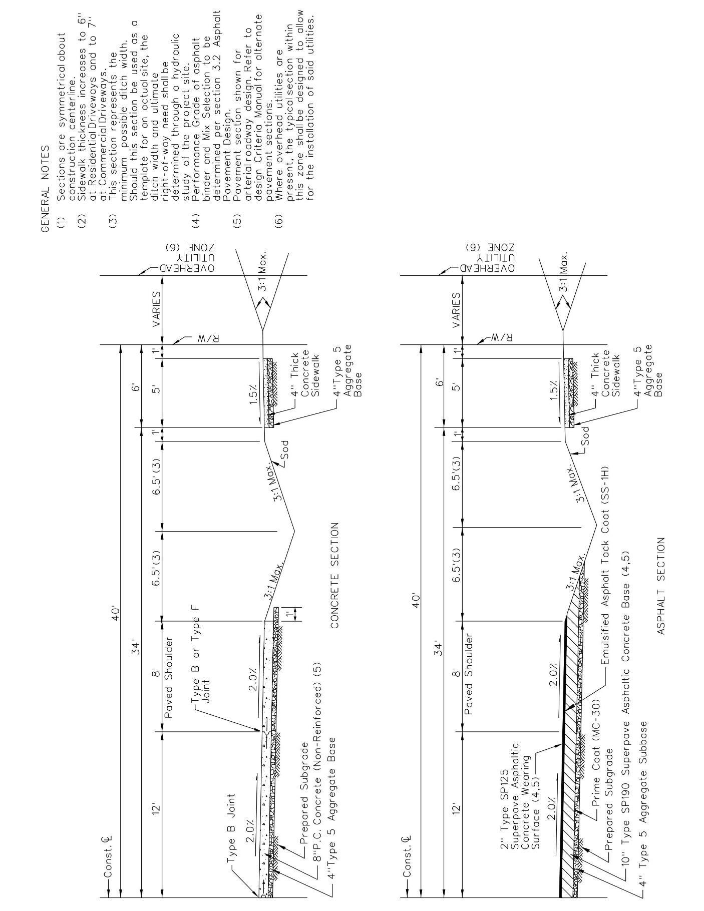
Design Requirements Page | 5-54 9/25/2023 Design Criteria Manual
Figure 5.6-1 - 2 Lane, 8’ Shoulder, Open Drainage
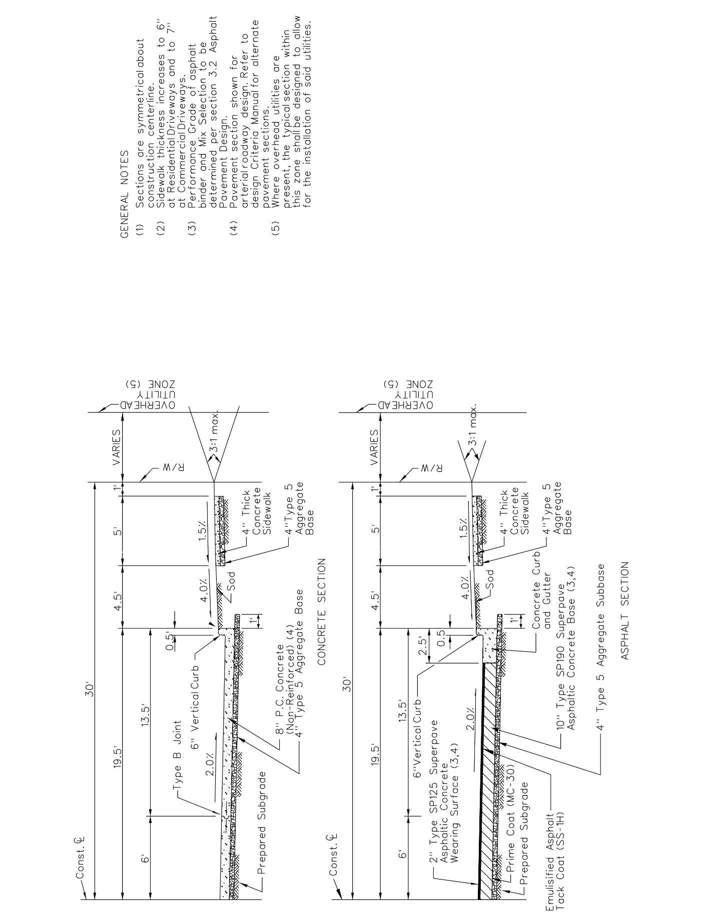
Design Requirements Page | 5-55 9/25/2023 Design Criteria Manual
Figure 5.6-2 - 3 Lane Urban, No Shoulder, Enclosed Drainage
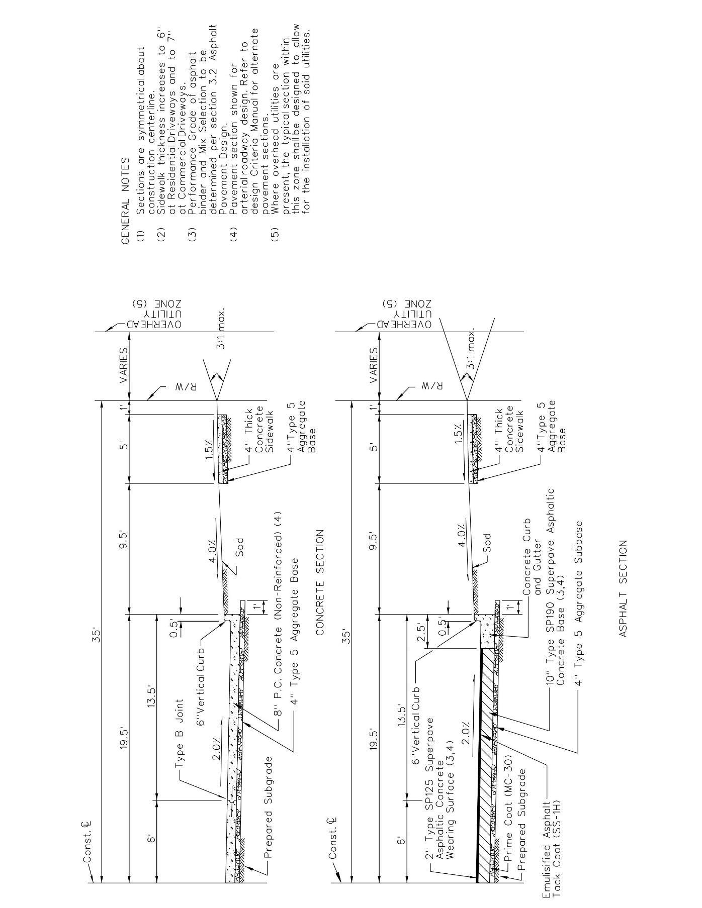
Design Requirements Page | 5-56 9/25/2023 Design Criteria Manual
Figure 5.6-3 - 3 Lane, No Shoulder, Enclosed Drainage
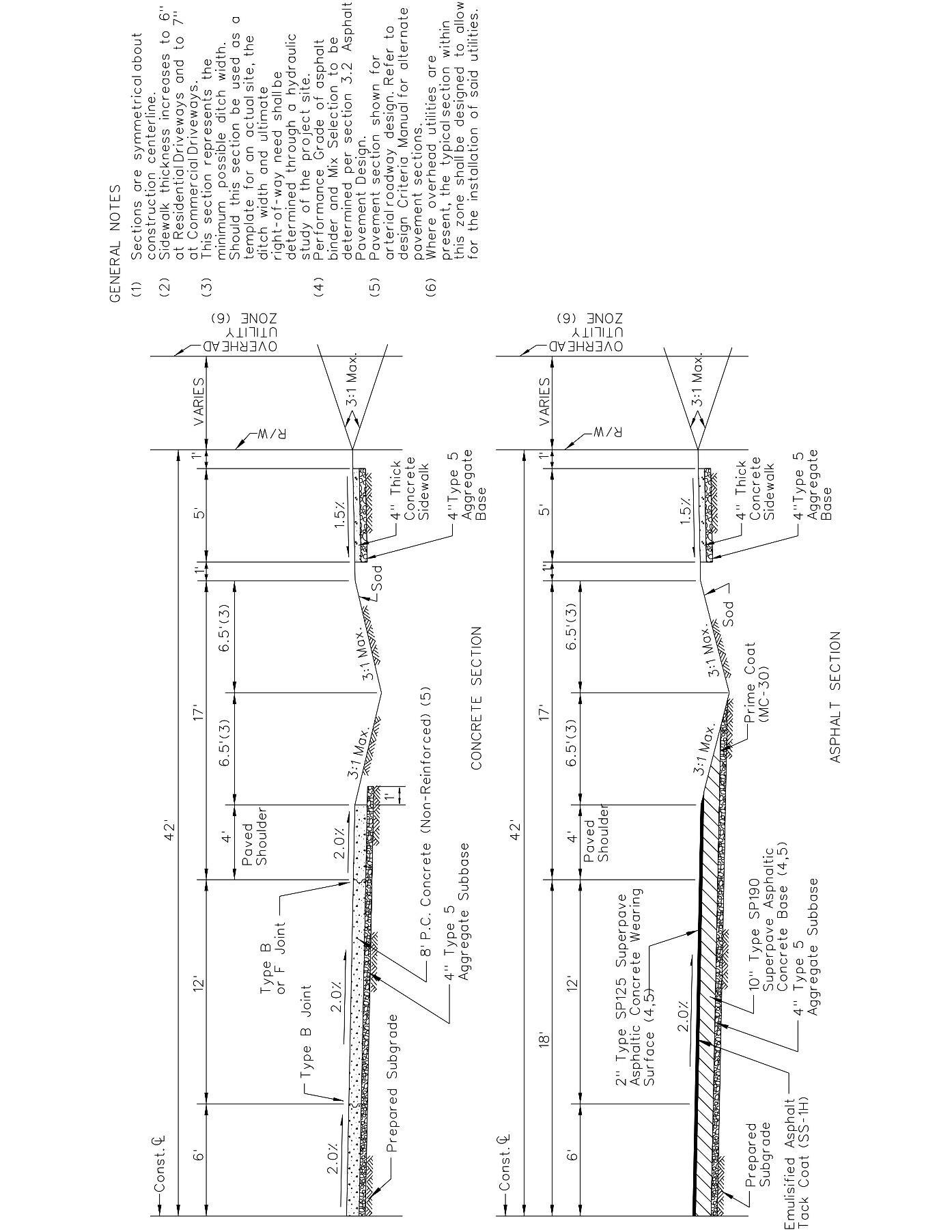
Design Requirements Page | 5-57 9/25/2023 Design Criteria Manual
Figure 5.6-4 – 3 Lane Rural, 4' Shoulder, Open Drainage

Design Requirements Page | 5-58 9/25/2023 Design Criteria Manual
Figure 5.6-5 - 4 Lane, No Shoulder, Enclosed Drainage
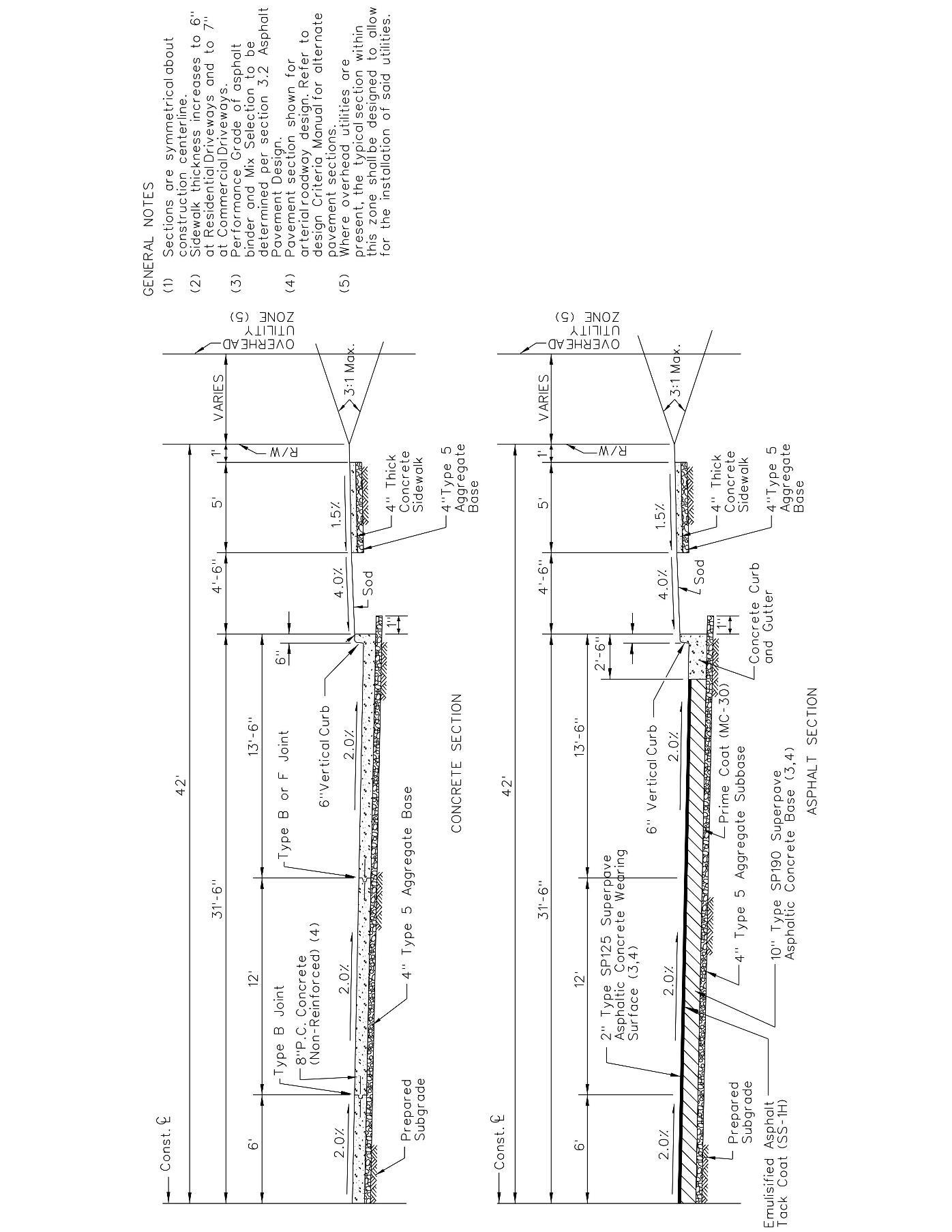
Design Requirements Page | 5-59 9/25/2023 Design Criteria Manual
Figure 5.6-6 - 5 Lane, No Shoulder, Enclosed Drainage
5.7 Intersection Geometric Design - All intersections shall comply with supplemental Drawing 5.1; Intersection Approach Requirements and each intersection approach shall provide for sight distance in accordance with supplemental Drawing 5 2 Sight Distance at Intersections Where frequent truck movements are expected; for roadways such as known truck routes, roadways which serve industrial developments, or roadways which serve commercial developments; sight distance shall be provided for both Passenger Cars and Trucks.
Intersection approach and receiving lane offsets should be avoided. Opposing exclusive left-turn lanes should have no offsets so that they directly align opposite each other. If a left turn lane is offset into the path of the approaching through lane, the left turning driver might assume that the approaching vehicles are also in a left turn lane and fail to yield. Also, when a left turn lane is offset too far right of the centerline, the opposing left turning vehicles may obstruct visibility of opposing through vehicles.
For through movement traffic, the approaching lanes should line up with the receiving lanes. Because of their geometry, skewed intersections are difficult to signalize and delineate. Keep the skew angle as close to 90 degrees as possible to provide more normal approaches and exits.
If roadway approaches and driveways/commercial entrances are located too close to an intersection, then traffic from these facilities can affect the intersection level of service. Consider restricting the access to right in / right out operation.
Public transit "stop”, and "pull-out" locations can adversely affect intersection operation. When possible, locate these "stops" and "pull-outs" on the far side of the intersection.
Stop lines define the point where vehicles must stop to not be in the path of the design vehicle’s left turn. Check the geometric layout based on the design vehicle’s turning radii. At signalized intersections, check the turning paths of opposing left turn movements to ensure this operation is possible for concurrent left turn movements.
Roadway crown for themajormovement atthe intersection oftwo roadwaysshall be held constant through the intersection. The minor roadway shall be warped to meet the major roadway. Where two roadways of similar function intersect, both roadways shall be warped to minimize cross slope grade changes for both movements through the intersection.
All roadways shall intersect with an interior angle between seventy (75) to ninety (90) degrees unless otherwise approved by the Department.
For all intersections, right-of-way shall be established a minimum of 1 foot behind the ultimate sidewalk, or alternate pedestrian facility, location. Additional right-of-way or permanent easements shall be dedicated for signal equipment, retaining walls, guard rail, or other facilities which require County maintenance or as directed by the Department.
Design Requirements Page | 5-60 9/25/2023 Design Criteria Manual
5.7.1 Design Vehicles - The standard design vehicle for all arterial, collector, non-residential local shall be the WB-62. The standard design vehicle for residential local roadways shall be the SU-40. The Department may require a larger design vehicle where larger vehicles are known to frequently travel the corridor; for roadways such as known truck routes, roadways which serve industrial developments, or roadways which serve commercial developments which are frequented by larger vehicles. Design exceptions for the use of a smaller design vehicle will typically require a traffic study.
5.7.2 Roadway Intersection Encroachment Allowances - The underlying design control in establishing pavement corner radii is the need to have the design vehicle turn within the permitted degrees of encroachment into adjacent or opposing lanes. Figures 5.7-1 and 5.73 illustrate degrees of encroachment allowable without departmental approval based on the intersecting roadway types. The degree of encroachment varies significantly according to roadway type and balance the operational impacts to turning vehicles against the safety of all other users of the roadway. Although the Exhibits provide a starting point for planning and design, the designer must confirm the acceptable degree of encroachment during the project development process. Final determination of allowable encroachment will be at the discretion of the Department.
Design Requirements Page | 5-61 9/25/2023 Design Criteria Manual
A) No Encroachment Allowed.
B) Vehicle shall remain in departure lane with no encroachment on adjacent lanes and may use the full width of all receiving lanes in the direction of travel. No encroachment allowed into contraflow lanes on the receiving roadway.
C) Vehicle may use up to two (2) departure lanes and the full width of all receiving lanes in the direction of travel. No encroachment allowed into contraflow lanes on the receiving roadway.
D) Vehicle shall remain in departure lane with no encroachment on adjacent lanes and may use full width of receiving roadway, including contraflow lanes.
E) Vehicle may use up to two (2) departure lanes and the full width of the receiving roadway, including contraflow lanes.
F) Vehicle may use the full width of both the departure and receiving roadways, including contraflow lanes
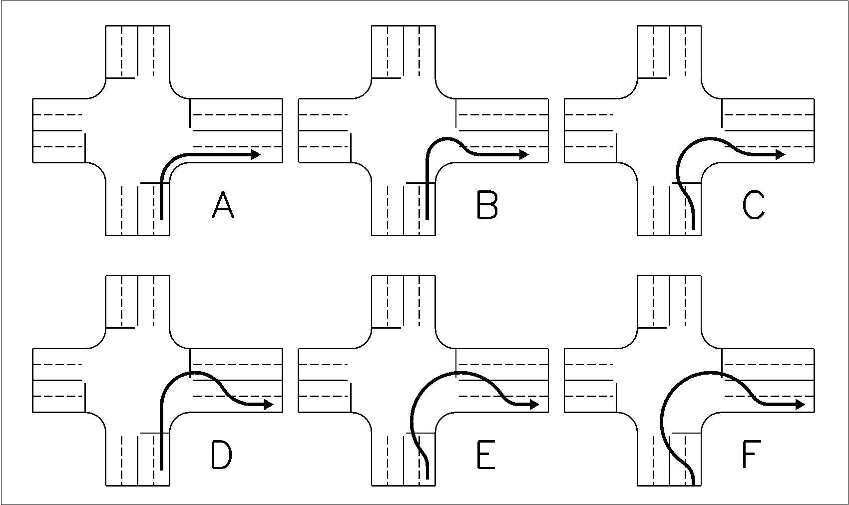
Design Requirements Page | 5-62 9/25/2023 Design Criteria Manual
Figure 5.7-1 - Non-Channelized Intersection Encroachment Classifications
Table 5.7-1 - Non-Channelized Intersection Encroachment Allowances
(1) Contact the department for specific requirements. Arterial to arterial connections will be evaluated on a case-by-case basis. To
Requirements Page | 5-63 9/25/2023
Criteria Manual
Design
Design
(Departure Street) Tractor/Trailer (WB-40 or larger) Arterial Collector Local Commercial Local Residential From (Approach Street) Arterial A (1) B C E Collector B B C E Local Commercial C C C E Local Residential C C F F
To
(Departure Street) Single Unit Truck (SU-40) Arterial Collector Local Commercial Local Residential From (A p proac h Street) Arterial A A B B Collector A A B B Local Commercial C C C C Local Residential C C C E To (Departure Street) Passenger Car (P) Arterial Collector Local Commercial Local Residential From (Approach Street) Arterial A A A A Collector A A A A Local Commercial A A A A Local Residential A A A A
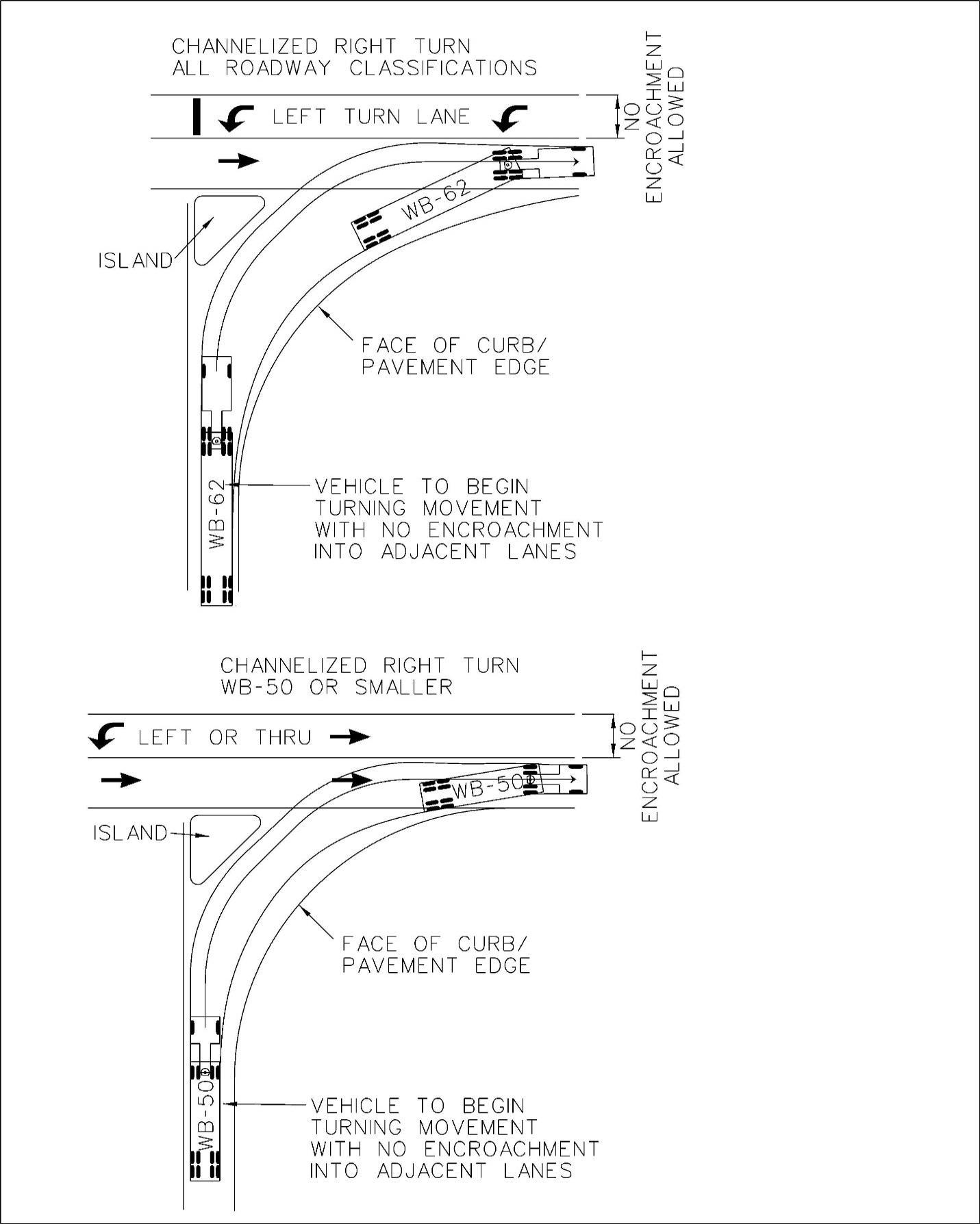
Design Requirements Page | 5-64 9/25/2023 Design Criteria Manual
Figure 5.7-2 - Channelized Intersection Encroachment Allowances
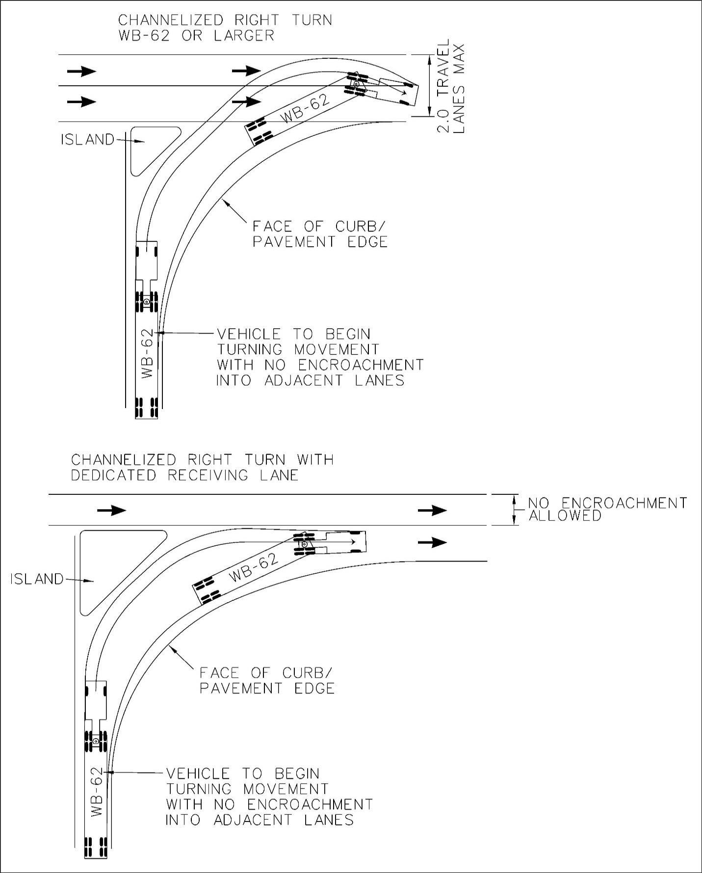
Design Requirements Page | 5-65 9/25/2023 Design Criteria Manual
Figure 5.7-3 - Channelized Intersection Encroachment Allowances
5.7.3 Corner Radii - The pavement corner radius, the curve connecting the edges of pavement of the intersecting streets is defined by either the curb or, where there is no curb, by the edge of pavement The pavement corner radius is a key factor in the multimodal performance of the intersection The pavement corner radius affects the pedestrian crossing distance, the speed and travel path of turning vehicles, and the appearance of the intersection.
Excessively large pavement corner radii result in significant drawbacks in the operation of the street since pedestrian crossing distance increases with pavement corner radius Further, the speed of turning motor vehicles making right turns is higher at corners with larger pavement corner radii The compounded impact of these two situations yields a significant deterioration in safety and quality of service to both pedestrians and bicyclists.
The corner radii of non-channelized intersections should be limited to 60' where possible within the encroachment allowances described in this chapter. Where the corner radii must exceed 60’ channelization should be strongly considered by the design engineer. In locations with heavy pedestrian movements the Department may require channelization of the right turn movement and the installation of islands or medians.
At the great majority of all intersections, whether curbed or otherwise, the pavement corner design is dictated by the right-turn movement. Left turns are seldom a critical factor in corner design, except at intersections of one-way streets, in which case their corner design is similar to that for right turns at intersections of two-way streets. The method for pavement corner design can vary as described below.
1) Simple Curb Radius - A simple radius (curb or pavement edge) is the preferred design for the pavement corner at non-signalized intersections with local roads The simple radius controls motor vehicle speeds, usually minimizes crosswalk distance and is easily designed and constructed.
2) Compound Curves or Taper/Curve Combinations - Where encroachment by larger motor vehicles must be avoided, where turning speeds higher than minimum are desirable, or where angle of turn is greater than 90 degrees, compound curves can define a curb/pavement edge closely fitted to the outer (rear-wheel) vehicle track Combinations of tapers with a single curve are a simple, and generally acceptable, approximation to compound curves.
3) Turning Roadways - A separate right-turn roadway, usually delineated by channelization islands and auxiliary lanes, may be appropriate where right-turn volumes are large, where encroachment by any motor vehicle type is unacceptable, where higher speed turns are desired, or where angle of turn is well above 90 degrees.
Design Requirements Page | 5-66 9/25/2023 Design Criteria Manual
5.7.4 Turning Movement Modeling - Intersection geometric design shall be based on the turning envelope of a design vehicle appropriate to the intersection (Table 5.7-2). Said intersections shall be evaluated with AutoTURN® turning movement modeling software. Exhibits demonstrating all allowed turning movements at said intersections shall be required by the Department prior to concept/site plan approval.
Required Turning Movement Model Parameters:
1) Turning movements shall be smooth with minimal steering corrections.
2) The minimum turning radius for any given design vehicle shall be per the AASHTO Green Book.
3) The minimum turning movement speed for left turns shall be 10mph.
4) The turning movement speed for right turns without dedicated receiving lanes shall be:
a) 10 mph minimum for movements onto Arterial roadways;
b) 10 mph minimum for movements onto Collector roadways;
c) 5mph minimum for movements onto local roadways.
5) The minimum turning movement speed for free flow right turns with dedicated receiving lanes shall be greater than 10mph and not less than 15mph below the posted speed limit on the receiving roadway.
6) A 2-foot offset shall be maintained between the design vehicle turning envelope and adjacent curb and island faces
7) Design vehicles shall be clearly labeled.
8) Where multiple overlapping turning movements on a single exhibit are difficult to interpret, the Department may require multiple exhibits for clarity.
Intersection geometric design requirements for signalized intersections and non-signalized intersections with channelized movements shall be as defined in design criteria supplemental Drawing 5 3, "Intersection Geometric Requirements"
The corner radii for non-signalized intersections without channelization shall be designed based on the turning envelope of a design vehicle appropriate to the intersection as described above for roadways which intersect at an angle less than 90 degrees or where either roadway is curved within 25' of the end of the corner radii For 90-degree intersections where neither roadway is curved within 25' of the end of the corner radii the corner radii may be established per Table 5.7-3
Design Requirements Page | 5-67 9/25/2023 Design Criteria Manual
(1) Contact the department of Transportation for specific requirements.
(2) Assumes WB-62 design vehicle; 90-degree intersection angle; and encroachment of a full lane (Table 5.7-1 Case B) on the receiving leg of the turning movement. Where any of these criteria is not met Table 5.7-3 is not applicable.
(3) Assumes WB-62 design vehicle; 90-degree intersection angle; and encroachment of a full lane (Table 5.7-1 Case C) on the departure and receiving legs of the turning movement. Where any of these criteria is not met Table 5.7-3 is not applicable. The Department may require a larger radii or channelization where local roads serve commercial/industrial developments which use larger vehicles.
(4) For alteration projects, the required radii shall not be smaller than that required to accommodate the largest vehicle known to travel the existing corridor.
5.7.5 Medians - Raised median strips may be required by the Department to restrict through and/or left turning movements at or near driveways, commercial entrances and/or street intersections. Raised medians may also be utilized for ornamental entrance monuments and signs on local roads. Median width shall be 6 feet minimum where the median will serve as a pedestrian refuge and 4 feet minimum elsewhere. Medians on local roads may be used for the installation of entrance monuments provided said monument does not hinder sight distance or future development of the road network as determined by the department. Refer to Section 5.19 Landscaping.
5.7.6 Warping Detail Requirements - Warping details shall be provided for all intersections. Warping detail minimum requirements shall be defined by supplemental Drawing 5 5, "Warping Detail Requirements".
Design Requirements Page | 5-68 9/25/2023 Design Criteria Manual
Roadway Classification Arterial Collector NonResidential Local Residential Local Arterial n/a (1) 60' (2) 50' (3) 32' Collector 60' (2) 60' (2) 50' (3) 32' Non-Residential Local 50' (3) 50' (3) 50' (3) 32' Residential Local 32' 32' 32' 32'
Table 5.7-3 - Corner Radii for Non-Signalized and Non-Channelized 90 Degree Intersections
5.8 Pedestrian Facility Design
5.8.1 ADA General Requirements - The pedestrian access route within St. Louis County right-of-way or easement shall be designed and constructed in accordance with the St. Louis County ADA Checklist, St. Louis County Standard Drawings, St. Louis County Standard Specifications, and the current published federal guideline for accessibility within the public right-of-way (Proposed Accessibility Guidelines for Pedestrian Facilities in the Public Rightof-Way, July 2011 at the time of publication). Should the current published federal guidelines provide a higher level of accommodation than the published St. Louis County standard, the federal guideline shall govern St. Louis County defines the term "ADA Compliant" as meeting the requirements stated above.
1) St. Louis County ADA Checklist and Standard Drawings - The St. Louis County ADA checklist and pedestrian facility related standard drawings are intended to be helpful tools for both the design and construction of pedestrian facilities within the public right-of-way and establishes the basis for the county's acceptance of work. Situations may arise where the checklist and standard drawings may not fully address all requirements needed to construct a facility to the full requirements of current ADA law or may not address site specific conditions. In those situations, the designer shall propose a solution is compliant with current ADA law using the following hierarchy of resources: PROWAG, a solution approved by the Access Board, or MoDOT's Engineering Policy Guidelines (EPG).
2) Accessible Pedestrian Crossing Location and Grade Requirements - Accessible pedestrian crossings (crosswalks) shall be located as depicted on supplemental Drawing 5 4 Accessible Pedestrian Crossing Requirements Cross slope in the direction of pedestrian travel and running slope parallel to the direction of pedestrian travel shall be as described in the St. Louis County ADA Checklist, Drawing 5 4 Accessible Pedestrian Crossing Requirements, and supplemental Drawing 5 1 Intersection Approach Requirements
New roadways and all pedestrian facilities which are constructed / reconstructed shall be constructed to meet all applicable ADA requirements.
Where roadway pavement will be reconstructed, cross slope and running slope shall be corrected within the pedestrian crossing except where such correction would create a vehicular safety concern.
Design Requirements Page | 5-69 9/25/2023 Design Criteria Manual
Where a project will not be reconstructing the pavement through a pedestrian crossing the Department will not require correction of cross slope or running slope deficiencies within the roadway. In this case, a segmental transition will be required between the existing roadway pavement and newly constructed curb ramps.
3) Sidewalk Construction - Sidewalks shall be a minimum of five (5) feet wide on arterial roads (ARS), county collector roads (CRS-2) and non-residential local street (CRS) sections, and a minimum of four (4) feet wide along residential local streets. A minimum sidewalk width of six (6) feet shall be required when sidewalks are adjacent to curbs for all development types. Additional width may be required in commercial areas at the discretion of the Department. Sidewalks shall be constructed of four (4) inch thick concrete, except across driveways and temporary turnarounds where the thickness shall be increased to match the driveway approach or adjacent pavement thickness (6 inches minimum where adjacent pavement is less than 6 inches thick), and curb ramps. For commercial entrances, the thickness of the first section of sidewalk or curb ramp on each side of the entrance shall be increased to match the driveway approach pavement thickness. When sidewalks are constructed where multiple standards (such as municipal ordinances or regulations) may apply, the more stringent standard will govern.
4) Curb Ramps - All curb ramps shall be fully ADA compliant. Design exceptions may be granted where full compliance is not possible due to site constraints outside of a developer’s control. Design exceptions shall not be granted due to the cost of required improvements.
5) Detectable Warning Surface - A detectable warning surface (truncated domes) shall be provided wherever an accessible route enters a roadway, commercial entrances which act as a roadway, and at signalized commercial entrances.
6) Segmental Transitions - When a new ADA compliant curb ramps is constructed adjacent to existing pavement a segmental transition must be constructed. A segmental transition is a warped area of pavement for the connection of the new ADA compliant curb ramp to the adjacent existing pavement and shall meet the following criteria:
a) Replacement of material in the segmental transitions shall match in kind the material removed. Asphalt transitions may be accomplished with a 2 inches depth mill and overlay or full depth replacement, as directed by the engineer. Concrete transitions must be full depth replacement.
b) Under most circumstances, the segmental transition length shall include an area equal to the size of the opening plus a distance of 5 feet in any direction to allow for connection to the grade of the adjacent pavement. Total size of the segmental transition may be altered as directed by the engineer.
c) The segmental transition shall be warped in a way which does not pond water or pose a hazard to motorists.
Design Requirements Page | 5-70 9/25/2023 Design Criteria Manual
d) The segmental transition shall not exceed a cross slope transition of 1% per foot in the direction of pedestrian travel.
e) The segmental transition shall not exceed a running slope of 5% in the direction of pedestrian travel.
f) Where milling and/or overlay operations intersect the newly constructed ramp, no additional pay will be made for constructing a flush connection between the pedestrian access route and the roadway.
5.8.2 Verification of Existing Pedestrian Facilities - Where the developer proposes to use existing pedestrian facilities in place, a St. Louis County ADA Checklist shall be completed for the complete pedestrian access route adjacent to the project site and submitted with the preliminary development plan.
Where existing pedestrian facilities will be used in place, a note signed and sealed by a Professional Engineer licensed in the State of Missouri shall be added to the final plans for all project types indicating that the unimproved existing pedestrian access route is ADA compliant.
5.8.3 Sidewalk Variances - Sidewalk construction shall be required in connection with all site development. Note that on sites that fall under the Subdivision Ordinance, the sidewalks shall be required unless waived through the Department of Planning variance procedure.
1) Only if the Department of Transportation determines that the required sidewalk cannot be built or construction of said sidewalk is not in the best public interest, will the developer be allowed to provide a Special Escrow to enable the construction of the sidewalk in the future. Examples where the Department would determine that the sidewalk should be built include, but are not limited to, the following:
a) Adjacent to an existing bridge.
b) Where an off-site easement is required, and the adjacent property owner will not grant said easement.
c) Along the frontage of a programmed or funded capital project.
d) Where extreme grade differentials prohibit sidewalk construction.
Design Requirements Page | 5-71 9/25/2023 Design Criteria Manual
5.8.4 Special Escrow for Pedestrian Facility Enhancements - When directed by St. Louis County, in lieu of sidewalk and related pedestrian facility construction, an Agreement Guaranteeing Road Improvement (Special Escrow, see Chapter 8 for requirements) together with a cash sum, may be required by the Department The Special Escrow shall include, but not be limited to, the following cost items:
1) ADA compliant concrete sidewalk; width of the pedestrian facility to be consistent with County Standards for the proposed location and function of the facility;
2) ADA compliant concrete curb ramps;
3) Concrete island construction;
4) Pavement widening and reconstruction necessary to facilitate island geometric modifications required for ADA compliance;
5) ADA related traffic signal modifications;
6) Grading (cut and/or fill); (± 2 feet)
7) Adjustment costs to driveways impacted by future sidewalk construction;
8) Adjustments to and/or relocation of storm water drainage facilities;
9) Sod installation.
The Special Escrow will not include the cost of utility relocation. Any additions or deletions of items from this list of cost items shall be as directed by the Department of Transportation. Special Escrow cost items shall be based on unit prices as listed in Chapter 8 The amount of the escrow is subject to the approval of the Department.
5.8.5 Sidewalk District - In areas where there are no sidewalks along County maintained roadways and residents desire the construction of sidewalks, a sidewalk district would be formed involving those properties that would benefit from the construction of a sidewalk. This may require dedication and/or acquisition of right-of-way and related easements and assessment to property owners in the sidewalk district to pay for the cost of construction. Contact the St. Louis County Counselor's Office for information regarding the requirements for formation of such sidewalk district.
5.8.6 Sidewalk Credits - Credit for sidewalk construction within the public road right-of-way will be given against required traffic generation assessment and/or trust fund contributions for the following:
1) Construction of new sidewalk beyond the site's frontage and adjacent to the public roadway when necessitated by road improvement requirements.
Design Requirements Page | 5-72 9/25/2023 Design Criteria Manual
2) Removal and reconstruction of all sidewalk necessitated by road improvement requirements set by the Department. Typically this credit will be associated with a road widening.
3) No credit is given for a sidewalk constructed within a development's public road frontage.
5.8.7 Pedestrian Facility Requirements for Residential Development - Compliant sidewalk and curb ramps shall be required along the frontage of all residential developments. Improvements to intersection signal equipment and intersection geometry solely for ADA compliance shall not be required for single lot development, residential lot splits which result in less than 5 lots, or subdivision developments less than 5 lots. Right-of-way and/or easement dedications may be required by the department to address future improvement needs. Development or re-development of 5 or more residential home sites shall provide intersection improvements per Section 5.8.8 Pedestrian Facility Requirements for Commercial Development.
Where sidewalk is not currently installed along a development’s frontage new sidewalk and curb ramps shall be constructed where said sidewalk provides a connection to an existing or proposed sidewalk network. Where said sidewalk will not connect to an existing or proposed sidewalk network, accommodation shall be made to install sidewalk at a future date and funds shall be escrowed for the value of said sidewalk. Accommodation for future sidewalk installation shall include design plans demonstrating ADA compliance, frontage shall be rough graded to the final elevation of the designed sidewalk, and property shall be dedicated necessary to construct the designed sidewalk. A Temporary Slope Construction License (TSCL) shall be provided at both ends of the development site to allow for the future sidewalk connection on the adjacent property.
All sections of existing sidewalk which are non-compliant shall be upgraded. Compliant sections of existing sidewalk may be used in place. Where an existing diagonal curb ramp is fully compliant it may be used in place. Where an existing diagonal ramp is non-compliant, split curb ramps shall be installed
In all cases, the sidewalk installed across a development’s frontage shall tie into a compliant connection or termination.
5.8.8 Pedestrian Facility Requirements for Commercial Development - Compliant sidewalk and curb ramps shall be required along the frontage of all commercial developments. All improvements at the intersection quadrant(s) immediately adjacent to the development necessary for full ADA compliance shall also be required. Intersection improvements include, but are not limited to, replacing non-compliant curb ramps, reconstructing diagonal ramps as split ramps, pavement geometric improvements, island geometric improvements, and traffic signal improvements.
Where sidewalk is not currently installed along a development’s frontage new sidewalk and curb ramps shall be constructed where said sidewalk provides a connection to an existing or proposed sidewalk network. Where said sidewalk will not connect to an existing or proposed sidewalk network, accommodation shall be made to install sidewalk at a future date and funds shall be escrowed for the value of said sidewalk. Accommodation for future sidewalk
Design Requirements Page | 5-73 9/25/2023 Design Criteria Manual
installation shall include design plans demonstrating ADA compliance, frontage shall be rough graded to the final elevation of the designed sidewalk, and property shall be dedicated necessary to construct the designed sidewalk. A Temporary Slope Construction License (TSCL) shall be provided at both ends of the development site to allow for the future sidewalk connection on the adjacent property.
All sections of existing sidewalk which are non-compliant shall be upgraded. Compliant sections of existing sidewalk may be used in place. Diagonal curb ramps shall be upgraded to split curb ramps.
In all cases, the sidewalk installed across a development’s frontage shall tie into a compliant connection or termination.
When, at the sole discretion of the Department of Transportation, signal and/or geometric improvements to the quadrant(s) immediately adjacent to the development also require improvements to opposing quadrants of said intersection for safe pedestrian or vehicular operation. In lieu of construction activities at said opposing quadrant(s), an Agreement Guaranteeing Road Improvement (Special Escrow, see Chapter 8 for requirements) together with a cash sum and a dedication, to the extent possible by the development, of the property rights necessary to construct the ultimate improvements, including temporary working room, shall be required by the Department. The requirements of said escrow are established in Section 5.8.4, Special Escrow for Pedestrian Facility Enhancements.
5.9 Entrance Design - All entrance construction within St. Louis County roadway right-of-way shall be constructed in accordance with the St. Louis County Department of Transportation's "Standard Specifications for Road and Bridge Construction" and shall meet sight distance requirements applicable to the allowable turning movements. Sight distance shall meet the requirements for both passenger vehicles and trucks for commercial and industrial development entrances which will serve truck traffic.
5.9.1 ADA Compliance - When a new entrance is installed or an existing entrance is reconstructed, said entrance shall be designed to allow for a fully ADA compliant pedestrian crossing, regardless of the presence of sidewalk adjacent to the entrance.
1) For entrances not under signal control, the cross slope of the pedestrian route thru the entrance shall not exceed 1.5% (+/- 0.5%) in the direction of pedestrian travel.
2) For entrances under signal control, the cross slope of the pedestrian route thru the entrance shall not exceed 4.5% (+/- 0.5%) in the direction of pedestrian travel.
3) The width of the pedestrian route thru an entrance shall be 5 feet minimum along all Arterial roadways, Collector roadways and internal to commercial subdivision developments, 4 feet minimum internal to residential subdivision developments, and 6 feet minimum where the adjacent sidewalk is at the back of curb regardless of development type.
4) Pavement crosswalk markings are not required at pedestrian crossings thru entrances.
Design Requirements Page | 5-74 9/25/2023 Design Criteria Manual
5.9.2 Entrance Sight Distance - Sight distance criteria shall be based upon the ultimate cross-section specified for the roadway being accessed. If required sight distance cannot be provided at the access location, acquisition of right-of-way, removal of plant material, reconstruction of pavement, and other off-site improvements, including appropriate Permanent Sight Distance Easements may be needed. Sight distance at access points shall meet the criteria in supplemental Drawing 5.2, Sight Distance at Intersections except as detailed below.
1) Commercial Driveways and Multi-Family Access Drives - These access points shall meet the criteria stated above.
2) Sight Distance at Residential Driveways Serving 3 Residential Lots or More, or Any Residential Driveway with Access on Roads Having an Ultimate CrossSection of Four (4) or More Lanes - These access points shall meet the criteria stated above but the driver's eye of the vehicle turning from the intersecting driveway shall be located twelve (12) feet from the edge of the outside lane of the roadway being accessed.
3) Sight Distance at Residential Driveways Serving 1 or 2 Residential Lots with Access on Roads Having an Ultimate Cross-Section of Two (2) or Three (3) Lanes - Sight distance represents a significant design control for residential driveways, and they should be located to provide the best visibility possible within the limitations of the property that each driveway serves. The sight distance for residential driveways should meet the minimum sight distance criteria for residential driveways serving 3 residential lots or more. If this criteria cannot be met, even with significant improvements to private property, or public property, the sight distances listed in Table 5.9-1 will be considered acceptable as the minimum required sight distance. The sight distance for the property access must be maximized, and a significant investment in the property features or public property may be necessary as a result. The sight distance for Table 5.9-1 (below) will be measured with the driver's eye of the vehicle turning from the intersecting driveway located twelve (12) feet from the edge of the outside lane of the roadway being accessed. All sight distance assumes grades of 3 percent or less, if greater see Table 5.9-2.
Design Requirements Page | 5-75 9/25/2023 Design Criteria Manual
Design Requirements Page | 5-76 9/25/2023 Design Criteria Manual
Design Speed (MPH)
Minimum
Distance for Residential Driveways Serving 1 or 2 Lots (feet) 15 85 20 135 25 180 30 240 35 300 40 390 45 480 50 570
4)
Table - 5.9-1
St Louis County
Sight
Approach Grade Design Speed (mph) 15 20 25 30 35 40 45 50 -9 1.1 1.1 1.2 1.2 1.2 1.2 1.2 1.2 -6 1.1 1.1 1.1 1.1 1.1 1.1 1.1 1.2 -5 1 1 1.1 1.1 1.1 1.1 1.1 1.1 -4 1 1 1 1.1 1.1 1.1 1.1 1.1 -3 to +3 1 1 1 1 1 1 1 1 +4 0 0 0 0 0 0.9 0.9 0.9 +5 0 0 0 0.9 0.9 0.9 0.9 0.9 +6 0 0 0.9 0.9 0.9 0.9 0.9 0.9 +9 0.9 0.9 0.9 0.9 0.9 0.9 0.9 0.9
Table 5.9-2 - Adjustment Factors for Table 5.9-1 Based on Approach Grade
5.9.3 Residential Entrances - Residential entrances on existing County roads shall not be less than ten (10) feet wide at the right-of-way line. When the distance between the sidewalk and pavement edge is less than four (4) feet, the minimum entrance width shall be twelve (12) feet.
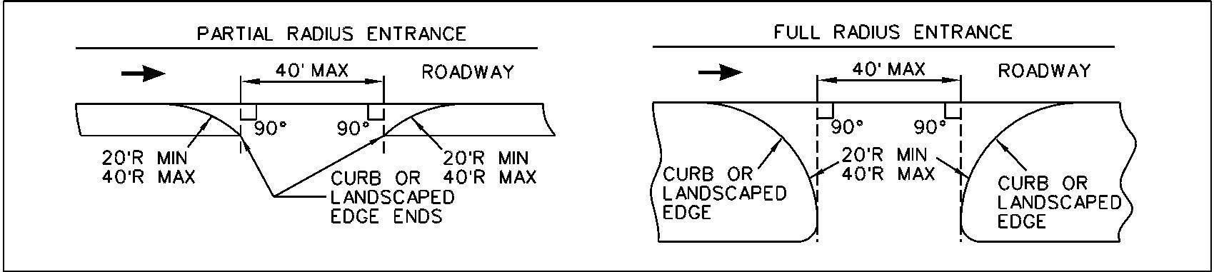
The distance between adjacent residential entrances shall be a minimum of twenty (20) feet measured along the road right-of-way line. When residential development conditions necessitate reduction of the distance between adjacent residential entrances to ten (10) feet or less, the Department may require a Common Entrance Approach.
Residential entrances on existing County roads shall be located so the edges of the curb opening shall be a minimum of five (5) feet from the nearest edge of street inlet sumps. The edges of the curb opening end of taper or end of rounding shall not project beyond the side property line extended normal to the pavement or a consent letter from the adjacent property owner shall be provided.
In the case of corner lots, entrances shall be located as defined in table 4.10-1. In addition, no driveways or other obstacles shall be constructed or placed within the corner triangle area bounded by the property lines of a corner lot and a line connecting two (2) points on the property lines each measured thirty (30) feet from the intersection of the two property lines at the intersection. Where applicable, easement lines shall be substituted for property lines.
Clearances and dimensions are shown on Figure 5.9-3.
5.9.4
Commercial
Entrances - Commercial entrances which are not signalized or channelized shall be designed to accommodate the largest vehicle anticipated to utilize the entrance but not be more than forty (40) feet wide at the point where edge delineation which physically limits vehicular movement, typically curbing or landscaping, ends measured perpendicular to the direction of travel of the adjacent roadway, see Figure 5.9-1. The radius used to increase the opening at the curb or pavement edge shall not be less than twenty (20) feet nor more than forty (40) feet. Exceptions to the width and/or radius may be required, or allowed with special approval by the Department, to insure adequate provisions for large vehicles and/or high traffic volumes.
Design Requirements Page | 5-77 9/25/2023 Design Criteria Manual
Figure 5.9-1 - Non-Channelized Commercial Entrance Restrictions
Commercial entrances shall be designed to allow passenger cars and frequent large vehicles (SU-30 or smaller) ingress and egress with no encroachment into adjacent travel lanes and limit encroachment of infrequent large vehicles (SU-40 and larger) into multiple lanes, see Figure 5.9-2. The infrequent large vehicle is typically a delivery vehicle which does not frequent a development more than three times a week.
For the infrequent case, encroachment shall only be allowed where the lane being encroached upon is in the same direction of travel or a center two way left turn lane. For right turns into a development, the largest design vehicle expected to service the site shall not require more than one and a half travel lanes along the roadway to complete the turning maneuver. For right turns out of a development, the largest design vehicle expected to service the site shall not require more than 2 travel lanes along the roadway on departure. No encroachment shall be allowed for left turn movements into a development. Where no access control island is required, and no other obstructions are present, large commercial vehicles may use the entire entrance width to complete ingress and egress turning movements. Where channelization is required, the entrance shall be designed in accordance with the channelization requirements presented in Section 5.7, Intersection Geometric Design Criteria.
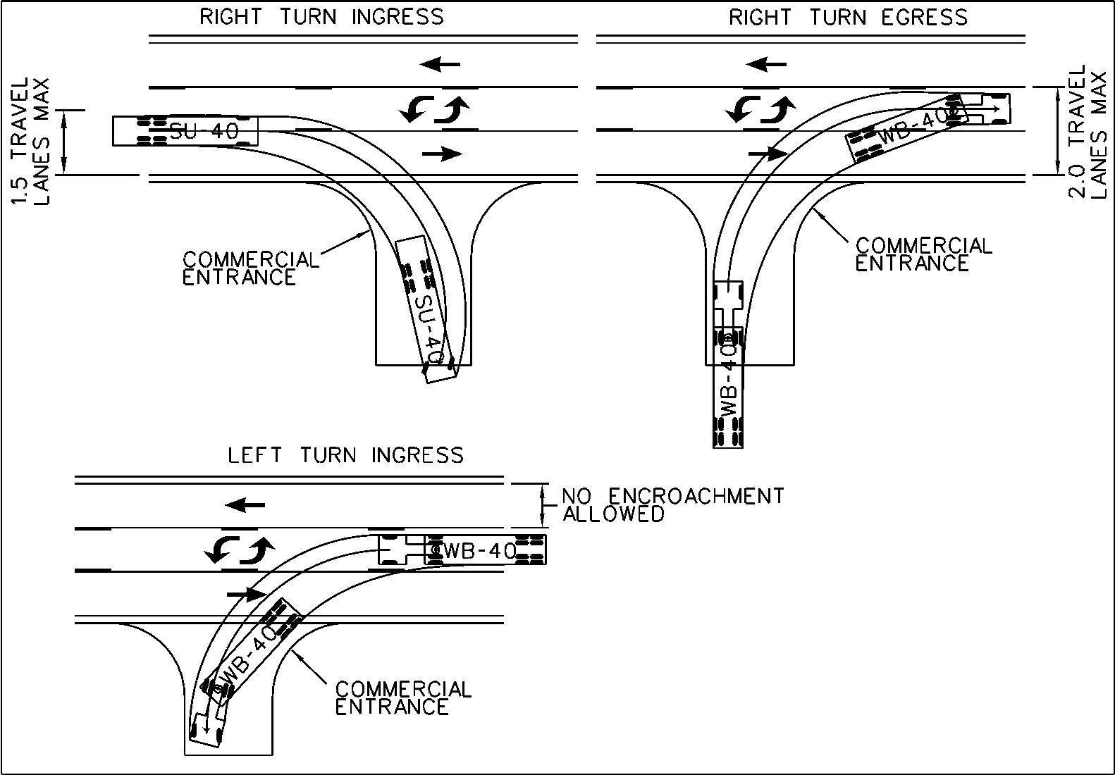
Design Requirements Page | 5-78 9/25/2023 Design Criteria Manual
Figure 5.9-2 - Maximum Allowable Encroachment the Infrequent Design Vehicle
Commercial entrances shall be located in accordance with the site plan requirements and shall be designed so the edges of the curb opening shall be a minimum of five (5) feet from the nearest edge of street inlet sumps The edges of the curb opening shall not project beyond the side property line extended normal to the pavement or a consent letter from the adjacent property owner shall be provided
In the case of corner lots, entrances shall be located as defined in Table 4.10-1. In addition, no parking spaces or other obstacles shall be constructed or placed within the corner triangle area bounded by the property lines of a corner lot and a line connecting two (2) points on the property lines each measured thirty (30) feet from the intersection of the two property lines at the intersection. Sign poles may be allowed if they are fifteen (15) inches or less in diameter and if the sign they support is not visually obstructing traffic at the intersection.
Clearances and dimensions are shown on Figure 5.9-3.
Design Requirements Page | 5-79 9/25/2023 Design Criteria Manual
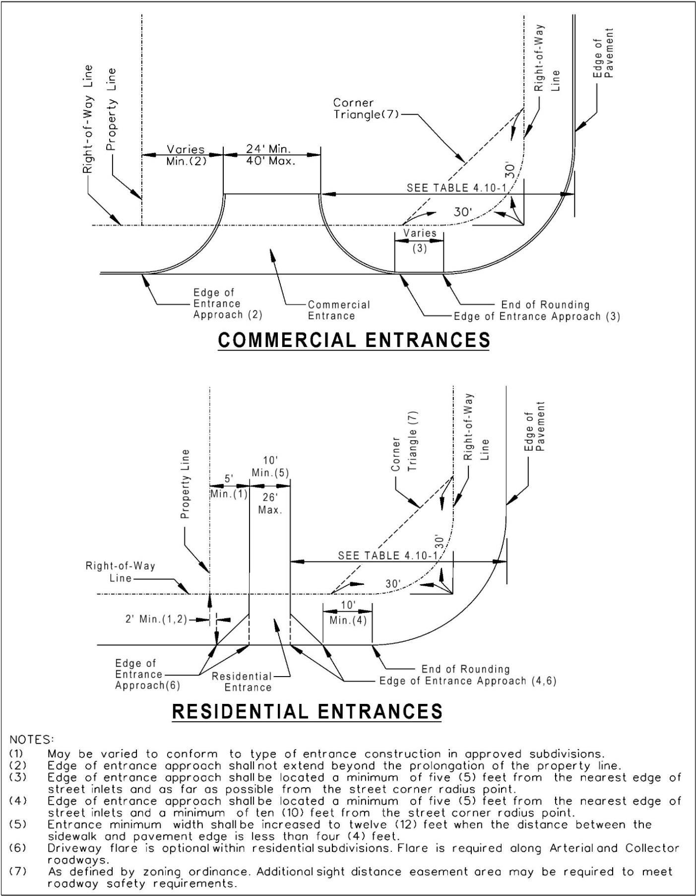
Design Requirements Page | 5-80 9/25/2023 Design Criteria Manual
Figure 5.9-3
The number of commercial entrances for each property or site shall be restricted on the basis of traffic requirements as determined by the Department. The maximum number of commercial entrances allowed, if all traffic requirements are satisfied, shall be as indicated in the following guidelines:
Left Turn Restrictions (When Required by the Department)
More than 1000
As Directed by
Properties that have frontage on two or more streets shall have the number of commercial entrances on each street restricted in accordance with traffic requirements and the above guideline. The distance between adjacent commercial entrances shall be a minimum of one hundred (100) feet measured along the road right-of-way line, unless otherwise approved by the Department. When feasible, opposing commercial entrances should be aligned opposite or should be offset a minimum of 100 feet. Higher volume driveways may require greater offset to be determined by the Department.
For a service and/or gas station or a convenience store with gas sales development on a corner lot, the following guidelines are established:
1) For a new development on a lot for which previous use was not associated with service and/or gas station or a convenience store with gas sales: One (1) entrance intersection from each street shall be permitted and located as far as possible from the street intersection corner.
2) For redevelopment (complete rebuilding) of a lot for which present use is associated with service and/or gas station or a convenience store with gas sales which is presently served by less than three (3) entrances: One (1) entrance intersection from each street shall be permitted at a location approved by the Department.
Requirements Page | 5-81 9/25/2023 Design Criteria Manual
Design
Max. Number Method of Commercial of Frontage (feet) Entrances ______________________ Restriction Less than 200 One (1) Median 200 to 500 Two (2) Median or Right In-Right Out Channelized Entrance 500 to 1000 Three (3) Median or Right In-Right Out Channelized Entrance
Median
or the Department Right In-Right Out Channelized Entrance
For redevelopment of a present use, which is presently served by three (3) or more entrances: The two (2) entrances located farthest from the corner may remain. The entrance located nearest to the corner on the inbound approach of the intersection shall be removed and the right-of-way restored to surrounding conditions or improved as required. The entrance located nearest to the corner on the outbound approach of the intersection may remain provided that this entrance is restricted, where required by the Department, to right turns in and right turns out by an existing or required median.
For remodeling or renovation of an existing use (i.e. canopy addition, island replacement or addition, dispenser replacement or addition, sales area renovation or addition, car wash addition) all existing entrances shall be permitted to remain except when changes to circulation patterns to the driveways result in an increased emphasis on the entrance located nearest the inbound approach of the intersection. Such entrance shall then be subject to further review and possible elimination by the Department.
5.9.5 Left Turn Restrictions - The restriction of entrance turning movements will require the construction of right in - right out channelized entrances, full access - right out channelized entrances, or raised median, as directed by the Department, based upon proximity to the nearest intersecting street or driveway, left turn storage requirements within the public rightof-way, development land use and traffic generation, sight distance limitations and cross access provisions as indicated in the above guidelines.
Where left turns are restricted by the construction of right in right out channelization islands, the Department will require such turning restrictions to be legislated by the applicable city and/or county authority prior to opening the entrance to traffic.
Restricted access entrance design requirements are shown in figures:
Figure 5.9-4 Right In-Right Out, Frontage Less Than 250 feet
Figure 5.9-5 Full Access In-Right Out, Frontage Less Than 250 feet
Figure 5.9-6 Right In-Right Out, Frontage Greater Than 250 feet
Figure 5.9-7 Full Access In-Right Out, Frontage Greater Than 250 feet
Design Requirements Page | 5-82 9/25/2023 Design Criteria Manual
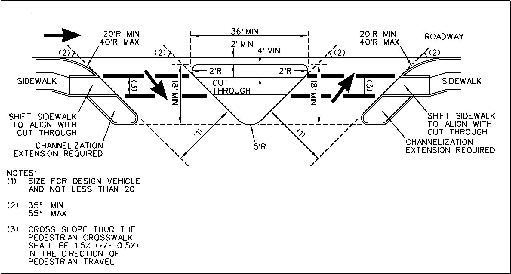
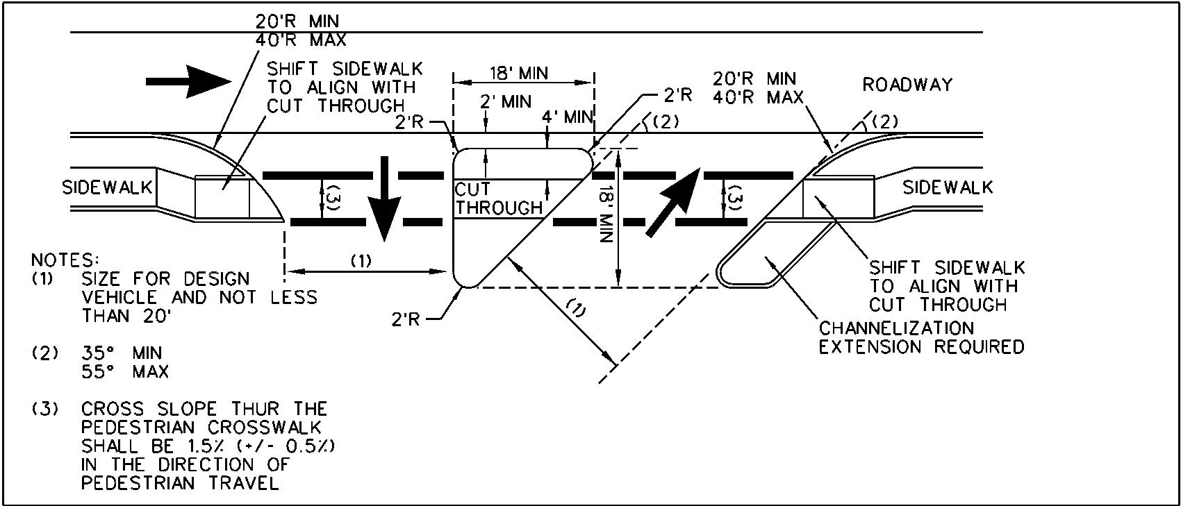
Design Requirements Page | 5-83 9/25/2023 Design Criteria Manual
Figure 5.9-4 - Right In-Right Out, Frontage Less Than 250 Feet
Figure 5.9-5 - Full Access In-Right Out, Frontage Less Than 250 Feet
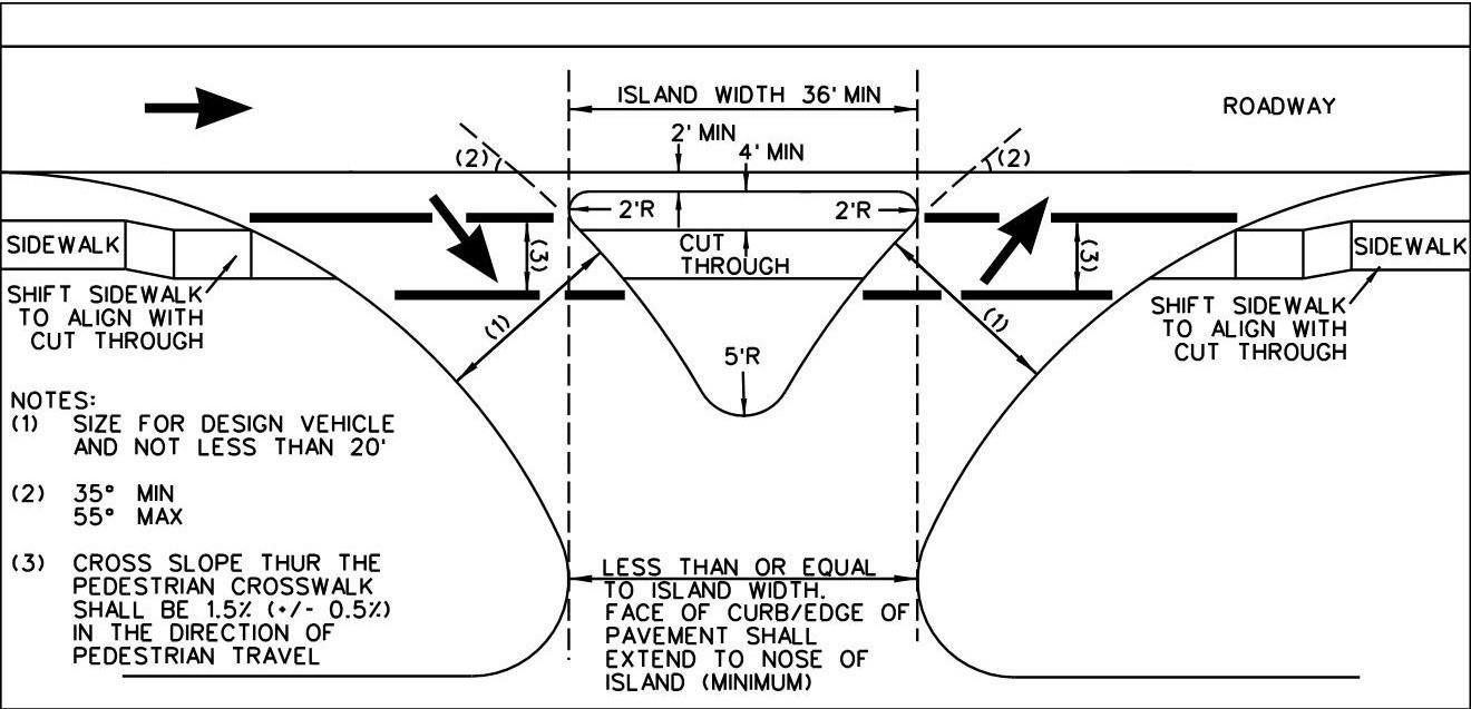
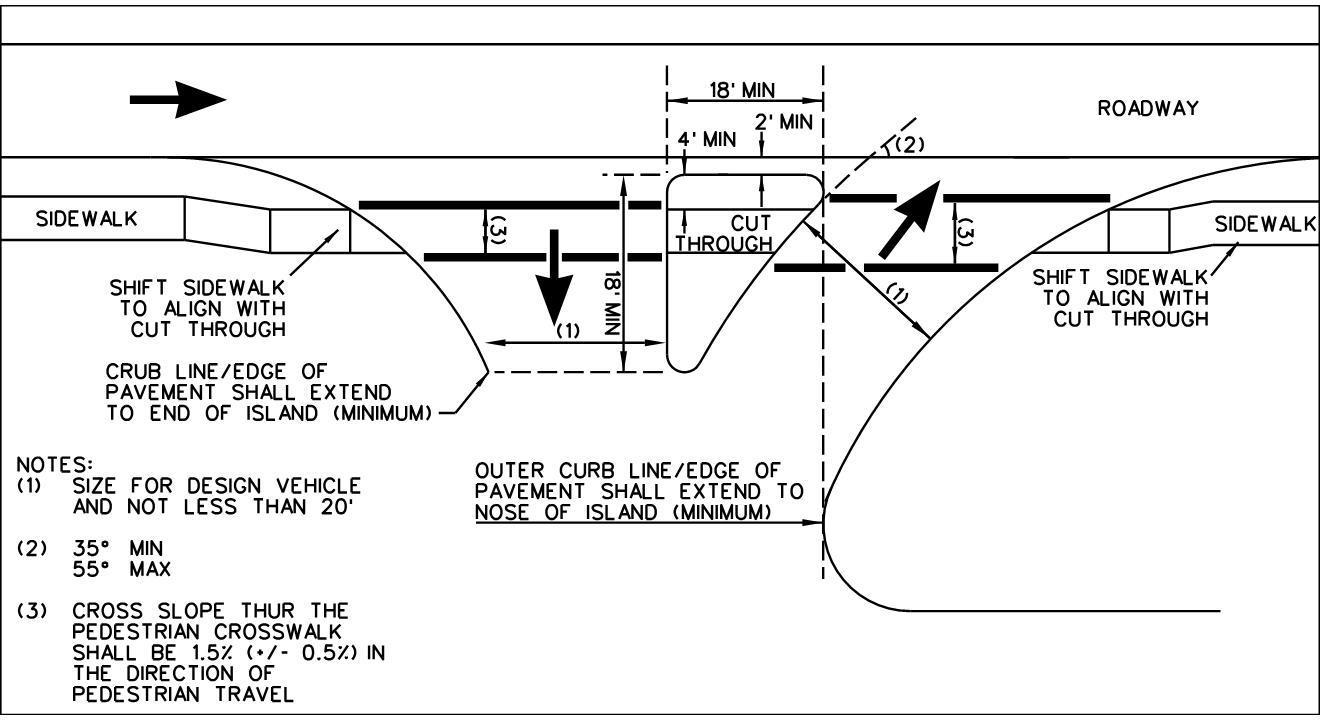
Design Requirements Page | 5-84 9/25/2023 Design Criteria Manual
Figure 5.9-6 - Right In-Right Out, Frontage Greater Than 250 Feet
Figure 5.9-7 - Full Access In-Right Out, Frontage Greater Than 250 Feet
5.9.6 Entrance Clearance - Residential and commercial driveway entrance locations which do not meet the side property line clearance requirements shall not be approved for construction without a consent letter from the abutting property owner.
5.9.7 Temporary Emergency Access - In certain instances, the Department of Transportation may grant temporary access to roadways for emergency vehicles only. The access shall be a 12-foot wide, 12-inch thick rock drive with a standard paved approach within the right-of-way constructed of Type "X" Bituminous Concrete Base - 6" thick and Type "C" Bituminous Concrete Wearing Surface - 2" thick. A gate must be provided across the drive at the right-of-way line with the sign, "Emergency Vehicles Only" on each side of the gate. The gate shall have a lock with the only keys thereto in possession of the St. Louis County Department of Transportation, the St. Louis County Police Department, and the appropriate Fire Protection District.
5.9.8 Loading Docks - Loading docks shall be designed so that trucks shall not be forced to maneuver on public or private streets.
A paved area of seventy-five (75) feet in depth (not including public or private street right-ofway) as measured at right angles to the loading dock shall be required for proper maneuvering of large vehicles.
For additional requirements, refer to the St. Louis County Zoning Ordinance, Section 1003.165, Supplementary Off-Street Parking and Loading Requirements.
5.9.9 Cross Access - Cross access is defined as a commonly shared or used pedestrian way or vehicular driveway that connects or serves two or more properties.
The purpose of cross access may be to reduce the number of entrance intersections to an arterial or county street, to provide access via a signalized intersection, to provide direct access between adjacent developments, to provide access to lots not having road frontage, etc.
Cross access may be required as part of the Site Plan or Subdivision Review Procedure, zoning request, and/or special procedure request and shall be provided in accordance with the following conditions:
1) At the time the site plan is submitted for review, the Department will identify adjacent existing land use and its potential for change, existing traffic volumes and design features of the surrounding roadways, etc. in order to ascertain requirements for cross access. If cross access is required, the plan shall show the area to be included for cross access to include the driveway approach, internal driving and parking lot aisles and their extension to the property line(s) at the area(s) designated for connection to adjacent property.
Design Requirements Page | 5-85 9/25/2023 Design Criteria Manual
2) If cross access has previously been established on adjacent property, the developer will be required to provide cross access and construct a pavement connection to the existing internal driving and parking lot aisle within that area of cross access. In the event that cross access has not previously been established on adjacent property, no pavement connection to adjacent property is required other than that necessary for the functioning of the site.
3) The area designated for cross access shall be kept free of all landscaping, fences, trash enclosures, parking/ loading spaces, and/or other improvements except as required by The Zoning Ordinance. Any approved improvements located in the areas designated for cross access shall be removed by the developer who is required to construct the pavement connection.
4) A Temporary Slope Construction License shall be provided to facilitate construction of the future cross access by the adjacent development or property owner. Maintenance of cross access areas shall be accomplished by each property owner or as may be agreed to by the owners. The owners shall provide copies of all such agreements to the Department for approval prior to execution and recording.
5) The Cross Access Easement Agreement the Temporary Slope Construction License provided in Chapter 7, may be duplicated for execution and submittal to the Department as part of the improvement plan approval.
6) Any modification of the Cross Access Easement Agreement shall be reviewed by the County Counselor and Departments of Transportation, Planning, Public Works and/or the Zoning Enforcement Officer and approved prior to execution and recording.
5.9 10 Gated Access - Gated access for private communities, commercial developments, etc. may be permitted for private residential streets, private commercial streets, etc., provided that an approved turnaround per County standards, is constructed prior to the gate.
5.9.11 Alternate Dustproof Surfaces - Section 1003.165-2,4 (1) of the St. Louis County Zoning Ordinance states, "In all Zoning Districts, all parking and loading areas, including driveways, shall be paved, except in the "FP", "PS", "NU" and "R-1" Districts, where the Department of Transportation and the Department of Planning may approve an alternate dust proofing method."
The Departments of Planning and Transportation consider the following dustproof surfaces as acceptable alternatives to paving driveways and parking areas for single-family residential uses in the "NU", "FPNU", "R-1" and "FPR-1" Districts:
1) Bricks, Cobblestones, or Interlocking Pavers
a) Sand filled joints;
b) Clean sharp sand base (1½" thickness before compaction);
c) 6" of ¾" minus limestone sub-base;
d) Subgrade (compacted to 95% standard proctor).
Design Requirements Page | 5-86 9/25/2023 Design Criteria Manual
2) Chip and Seal Coat
a) 1 to 2 coats (⅜" to ¾") of bituminous surface treatments;
b) 6" gravel, crushed limestone, or soil cement stabilization (base primed);
c) Subgrade (compacted to 95% standard proctor).
3) C-Gravel
a) 8" of C-Gravel (¾" + non-crushed aggregate, such as that found in the Meramec River);
b) Subgrade (compacted to 95% standard proctor);
c) Use of manufacturer's specifications is recommended;
d) All thicknesses shown are minimum;
e) Use of a non-woven fabric underlayment between the subgrade and adjacent surfacing material is recommended.
The above described surfaces shall not be used for non-residential land uses in the above mentioned zoning categories, or for driveway entrance construction within the road right-ofway, which is required to meet St. Louis County standards and specifications.
5.9.12 Entrance Vertical Alignment - Driveway entrance grades shall be designed to allow for vehicles to enter at a reasonable speed to reduce the likelihood of rear end collisions and prevent vehicles from scraping or bottoming out on entry and egress. At a minimum, all driveway entrance shall be designed to accommodate a standard passenger car (Figure 5.911). Commercial driveway entrances should be verified against a set of design vehicles appropriate to the development type where the drive approach contains compound changes in grade. At a minimum, both the Passenger Car and the delivery vehicle type expected to service the development should be verified. Commercial entrances which are expected to receive high traffic volumes should ramp the pedestrian access route down to the entrance to allow for smooth vehicular transitions (See Special Commercial Entrance Standard Drawings)
When evaluating a driveway entrance for a site-specific design vehicle, it is important to consider suspension travel (dynamic loading) and cargo (static loading). It is recommended that a minimum 2” to 3” be subtracted from the resting height of the design vehicle to account for vehicle static and dynamic loadings.
The driveway grade guidelines below will provide for safe ingress and egress for an AASHTO Passenger Car design vehicle. This profile constraints outlined in this section apply across the entire driveway and are intended to be applied to the worst case condition, typically at the extreme edge line of any given driveway. This guideline does not consider trailers or other design vehicles. Where it is known that other vehicle types will be using any given driveway entrance, the designer shall evaluate the entrance design for the appropriate design vehicle. The limits provided below for the transition between G1 and G2, the transition between G2 and G3 and the maximum grade of G4 shall not be exceeded. The remainder of the guideline may be modified at the discretion of the engineer to address site specific constraints.
Design Requirements Page | 5-87 9/25/2023 Design Criteria Manual
(1) May be reduced to 4 feet within residential subdivision developments
1) Algebraic Difference Between G1 and G2:
a) Continuous Driveway Transition (Driveway grade connects at gutter line or edge of pavement):
i) Sag not to exceed 12% (9% maximum recommended for Commercial Developments)
ii) Crest not to exceed 8%
b) Transition from Rolled Curb (Driveway grade connects at back of rolled curb):
i) Sag not to exceed 6%
ii) Crest not to exceed 2%
2) Algebraic Difference Between G2 and G3:
a) Not to exceed 9%
3) Maximum Slope of G3 (pedestrian route) = 1.5% (± 0.5%) cross slope in the direction of pedestrian travel.
4) Algebraic Difference G3 to G4 and G4 to G5:
a) Commercial:
i) 0% - 6% crest: 5' vertical curve
ii) 6% - 11% crest: 10' vertical curve
iii) 11% - 16% crest: 15' vertical curve
iv) 0% - 6% sag: No vertical curve required
v) 6% - 11% sag: 5' vertical curve
vi) 11% - 16% sag: 10' vertical curve
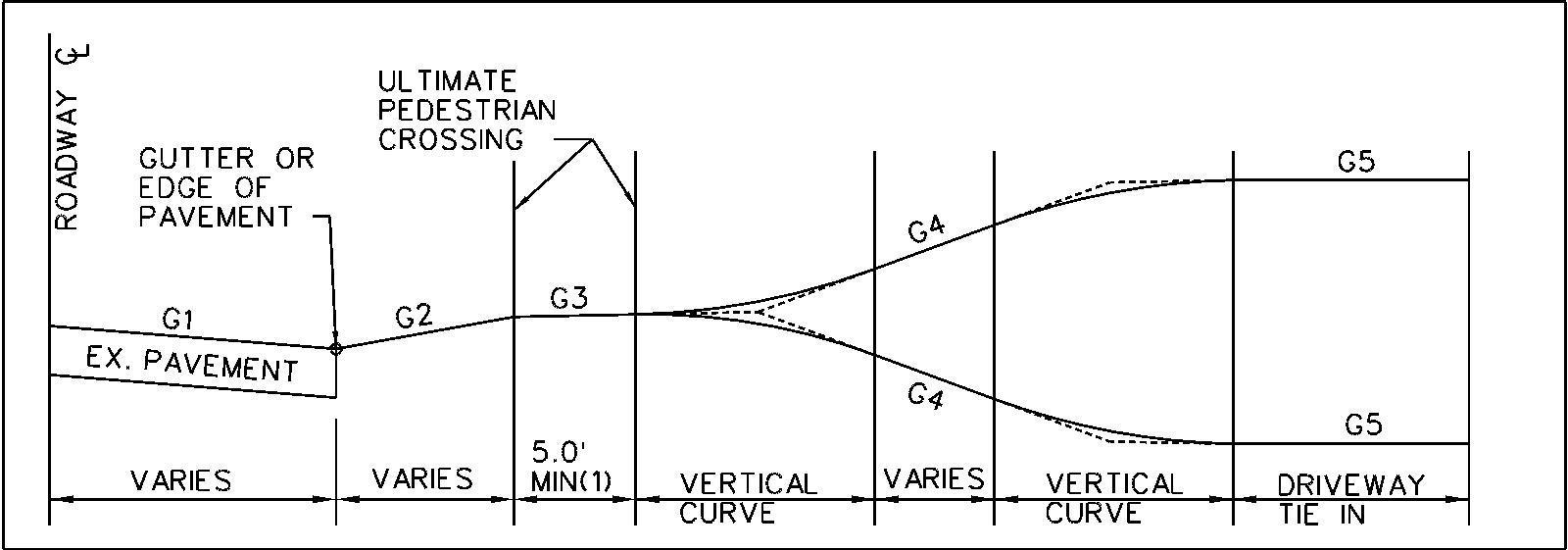
Design Requirements Page | 5-88 9/25/2023 Design Criteria Manual
Figure 5.9-8 - Driveway Profile with Vertical Curves
b) Residential:
i) 0% - 11% crest: 5' vertical curve
ii) 11% - 16% crest: 10' vertical curve
iii) 0% - 11% sag: No vertical curve required
iv) 11% - 16% sag: 5' vertical curve
5) Maximum Slope of G4:
a) Commercial:10%
b) Residential: Maximum grade is at the discretion of the designer. The guidance in this section is not applicable where G4 exceeds 16%.
6) The Department will allow the pedestrian access route to be depressed either partially (Figure 5.9-9) or fully (Figure 5.9-10) through a driveway entrance section where necessary to comply with the above grade restrictions provided the following conditions are met:
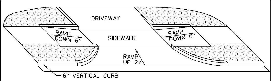

a) All such driveway entrance and sidewalk designs shall be fully ADA compliant.
b) Residential driveway entrances require departmental approval for depression of the pedestrian access route greater than 3 inches.
c) Water shall not pond or spread onto the sidewalk.
d) Site drainage shall not be adversely impacted.
Design Requirements Page | 5-89 9/25/2023 Design Criteria Manual
Figure 5.9-9 - Partially Depressed Entrance
Figure 5.9-10 - Fully Depressed Entrance

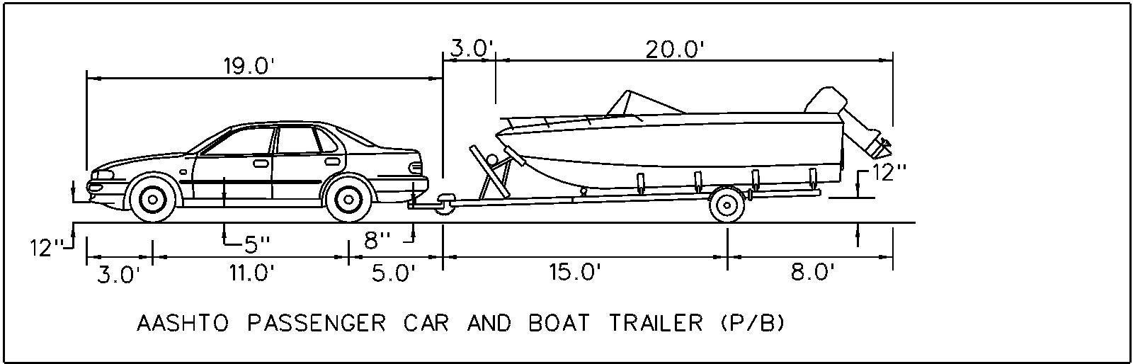
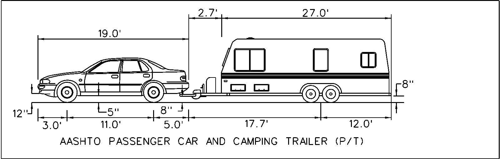
Design Requirements Page | 5-90 9/25/2023 Design Criteria Manual
Figure 5.9-11 - Sample Design Vehicles
5.10 Bicycle Path Roadway Crossing Guidelines - The number of bicycle shared-use paths will continue to increase throughout the St Louis County region. The popularity of these paths has attracted users ranging from bicycle enthusiasts to families with small children. In addition to the bicyclists, joggers, and walkers using the paths, patrons also include individuals on roller blades, babies in strollers, and children on bicycles with training wheels.
5.10.1 Importance of Traffic Controls for All At-Grade Bicycle Path/Roadway
Crossings - In light of the diverse nature of path users and the variety of non-motorized vehicles using the paths, standard traffic control devices shall be implemented for all County maintained at grade shared use path/roadway crossings by using these guidelines to enhance the safety of all path patrons and motorists. It has always been our policy to maintain uniformity in the application of traffic controls on the County’s road system. It should be noted that these guidelines do not address grade separated shared use path/roadway crossings at this time.
When designing a shared use path, consideration shall always be given to the type of existing traffic controls located within the vicinity of the proposed shared use path/roadway crossing. These existing controls may affect the location of the proposed path/roadway crossing, possibly requiring the route of the shared use path to be realigned on each side of the crossing.
5.10.2 Approved Traffic Controls at Bicycle Path/Roadway Crossings
- The types of traffic control used at bicycle path/roadway crossings shall be similar to the proven standard types of control currently in place at more than 750 County maintained marked crosswalk locations. Therefore, the types of traffic control devices approved by the County for use in conjunction with bicycle path/roadway crossings are:
• Raised pedestrian crosswalks or raised intersections on roadways with a 25 MPH speed limit. St. Louis County is developing and testing standards for these features. Any Developer desiring to implement this type of traffic calming must contact the Department to coordinate with our pilot program.
• Rapid Rectangular Flashing Beacons, in accordance with the Marked Crosswalk Policy.
• Mid-block marked crosswalks at path/roadway crossings, with stop control only for path users.
• Minor street stop control at intersecting roads, where there is a path/roadway crossing at the intersection.
• Multi-way stop control at intersecting roads, where there is a path/roadway crossing at the intersection.
• Pedestrian Traffic Signals, using MUTCD warrants for a Pedestrian Hybrid Beacon (PHB) as a substitute for the Pedestrian Volume signal warrant (MUTCD Warrant 4) As with all signal warrants in the MUTCD, the satisfaction of this warrant shall not in
Design Requirements Page | 5-91 9/25/2023 Design Criteria Manual
itself require the installation of a traffic control signal. The decision to install a traffic signal will be based on engineering judgement and available funding mechanisms.
• Intersection traffic signals, with pedestrian signal heads for path users.
5.10.3 Unapproved Traffic Controls at Bicycle Path/Roadway Crossings - The types of traffic control devices not approved by the County for use in conjunction with bicycle path/roadway crossings are:
• Full Time Flashing beacons along roadways, either in advance of or supplemental to pedestrian beacons or signals at path/roadway crossings
• Pedestrian Hybrid Beacons (PHB)
• In-roadway strobe lights at path/roadway crossings, activated by push buttons or microwave detection.
• Mid-block all-way stop control, with full time stop control for both motorists and path users at path/roadway crossings.
• Portable or turn-type (temporary) stop control.
• Raised pedestrian crosswalks or raised intersections on roadways with speed limits greater than 25 MPH. Exceptions may be made at the discretion of the Department for an exceptional and well-engineered pilot location. Any Developer desiring to implement this type of traffic calming must contact the Department to coordinate with our pilot program..
5.10.4 Concerns Regarding Unapproved Traffic Controls at Bicycle Path/Roadway Crossings - Proposals for the installation of full time flashing beacons and in-roadway strobe lights for shared use path/roadway crossings are not allowed on County roadways. The flashing lights could be confusing to motorists when used in the proximity of traffic signals. Many path users and motorists would not understand the meaning and function of the lights. Path users might assume they would always have the right-of-way. To address this concern, beacons usedfor path/roadway crossings shall only be active when user actuated, or a special condition is present such as an active school speed limit zone.
Section 1209.020 of the St. Louis County Traffic Code states the following regarding pedestrians’ right-of-way in crosswalks: "No pedestrian shall suddenly leave a curb or other place of safety and walk or run into the path of a vehicle which is so close that it is impossible for the driver to yield".
The installation of full-time flashing beacons along roadways at shared use path/roadway crossings would indicate to motorists the presence of a special condition. We believe that over time, drivers would become accustomed to flashing beacons installed at such crossings and the beacons would ultimately have no effect upon the yield rates of approaching motorists.
Design Requirements Page | 5-92 9/25/2023 Design Criteria Manual
As a result, unwarranted full time flashing beacons installed in this type of indiscriminate manner would reduce the effectiveness of all beacons.
The installation of mid-block all way stop control at shared use path/roadway crossings would cause unnecessary inconveniences and delays for motorists when no path users are present. Past experience has shown, that under this type of control, many path users do not abide by the "Stop" signs facing them. They assume approaching motorists will stop and remain stopped at the crossings. Therefore, path users often continue to walk/ride across the roadways without stopping. We believe this behavior of path users is difficult to control and is a safety concern.
Portable or turn type (temporary) "Stop" signs are not permitted for normal roadway use, as indicated in the Manual on Uniform Traffic Control Devices (MUTCD), which is published by the Federal Highway Administration. These types of "Stop" signs produce a level of uncertainty which causes confusion for motorists, thereby increasing the potential for crashes. These types of "Stop" signs also create an administrative problem with any unauthorized moving/turning of the signs.
The construction of traffic calming roadway features, such as speed bumps, speed humps, speed tables, raised pedestrian crosswalks, raised intersections, center medians with short tapers, and narrower pavement sections (chicanes and chokers) at shared use path/roadway crossings requires careful consideration and engineering. The Department will evaluate requests for the installation of these features on a case-by-case basis. Where such features are desired, Developers should contact the County as early as possible to review options, evaluate site specific concerns, and develop site specific draft standards.
5.10.5 Traffic Control Criteria for Bicycle Paths Crossing Through/Collector/Arterial Type Streets
The following conditions shall be used as the criteria for determining the type of traffic control to be implemented for each shared use path crossing a through/collector/arterial type street. The conditions shall be analyzed in the following priority:
Condition 1 - If the proposed path/roadway crossing is within 300 feet of an existing mid-block or intersection traffic signal, the path/roadway crossing shall be located at the existing traffic signal.
Condition 2 - If the proposed path/roadway crossing is within 300 feet of an existing intersection with all way stop control for motorists on the roadway, the path/roadway crossing shall be located at the existing intersection and include stop control for path users.
Condition 3 - If the proposed path/roadway crossing is 100 feet minimum, or can be located to 100 feet minimum, from an adjacent cross street/public entrance with side street stop only, a new mid-block traffic signal shall be installed at the proposed crossing if the street has four lanes or more. Streets with less than four lanes should have stop control for path users unless the amount of pedestrians crossing are expected to be high enough to meet signal warrants, as published in the MUTCD.
Design Requirements Page | 5-93 9/25/2023 Design Criteria Manual
Condition 4 - If the proposed path/roadway crossing cannot be moved to 100 feet minimum from an adjacent cross street/public entrance with side street stop only, the path/roadway crossing shall be located at the adjacent cross street/public entrance and a new intersection traffic signal installed in accordance with the procedures outlined in Condition 3.
The required 100-foot minimum distance from a new mid-block traffic signal at a proposed path/roadway crossing to an adjacent cross street/public entrance shall be determined as the distance from the prolongation of the edge of the side street nearest the proposed crosswalk to the near edge of the proposed crosswalk.
5.10.6 Traffic Control Criteria for Bicycle Paths Crossing Local Type Streets
The following Conditions shall be used as the criteria for determining the type of traffic control to be implemented for each bicycle path crossing a Local type street. The Conditions shall be analyzed in the following priority:
Condition 1 - If the proposed path/roadway crossing is within 300 feet of an existing mid-block or intersection traffic signal, the path/roadway crossing shall be located at the existing traffic signal.
Condition 2 - If the proposed path/roadway crossing is within 300 feet of an existing intersection with all way stop control for motorists on the roadway, the path/roadway crossing shall be located at the existing intersection and include stop control for path users.
Condition 3 - If the proposed path/roadway crossing is 100 feet minimum, or can be located to 100 feet minimum, from an adjacent cross street/public entrance with side street stop only, a new mid-block traffic signal shall be installed at the proposed crossing if the street has four lanes or more. Streets with less than four lanes should have stop control for path users unless the amount of pedestrians crossing are expected to be high enough to meet signal warrants, as published in the MUTCD.
Condition 4 - If the proposed path/roadway crossing cannot be moved to 100 feet minimum from an adjacent cross street/public entrance with side street stop only, the path/roadway crossing shall be located at the adjacent cross street/public entrance and a new intersection traffic signal installed in accordance with the procedures outlined in Condition 3.
5.10.7 Signage and Striping at Bicycle Path/Roadway Crossings - All final roadway signage, pavement markings, and striping on County roadways for shared use path crossings will be furnished and installed by the County. At each of these crossings, the signing and striping will be in accordance with the MUTCD. All signing and striping on shared use paths shall be furnished and installed by the agency responsible for the paths.
Design Requirements Page | 5-94 9/25/2023 Design Criteria Manual
Crosswalk markings at intersections for shared use path/roadway crossings will consist of two white parallel lines. Crosswalks at mid-block path/roadway crossings will consist of large white block markings.
Fluorescent yellow combined "Bicycle / Pedestrian Advance" warning sign assemblies with supplemental "Ahead" plaques will be installed in advance of each shared use path/roadway crossing facing approaching motorists. If the crossing does not have a traffic signal or "Stop" signs controlling approaching roadway traffic, fluorescent yellow combined "Bicycle / Pedestrian Crossing" warning sign assemblies with supplemental "Downward Arrow" plaques will be also installed at each path/roadway crossing facing approaching motorists. County personnel will also fabricate and install street name signs at each shared use path/roadway crossing, depicting the names of the shared use path and intersecting road(s).
5.10.8 County's Contribution Toward Signalization of Bicycle Path / Roadway Crossings – If, in accordance with these guidelines, a new mid-block or intersection traffic signal is required at a shared use path/roadway crossing, the County will review the signal plans and issue a Special Use Permit for the signal installation. All mid-block traffic signals and most intersection traffic signals shall have advance vehicle detection loops embedded in the roadway to enhance traffic flow and reduce the potential for rear-end type crashes. Signal interconnect conduit and cable shall also be installed unless directed otherwise by the County The agency responsible for the path shall be responsible for constructing the traffic signal in its entirety prior to the County’s final inspection and acceptance of the signal for maintenance.
The County will not participate in the costs of an agency’s modification of an existing traffic signal to accommodate a shared use path/roadway crossing unless the construction of the crossing can be coordinated with a County infrastructure project.
5.10.9 Summary - The County has always strived to maintain uniformity in the application of traffic controls on its roadway system. The guidelines herein are for at grade shared use path/roadway crossings across County maintained roads. Only standard traffic control devices are approved at these crossings and will serve to enhance the safety of all path patrons and motorists.
5.11 Roadside Design Requirements - The clear zone design criteria outlined in the AASHTO Roadside Design Guide shall govern for all roadway designs. The designer shall verify that all roadside hazards are either outside the clear zone or adequately protected to the greatest extent practicable. Above ground facilities which are not designed to be impacted by an errant vehicle; including utility poles, transformer boxes, signal controller cabinets, etc.; should be located outside the clear zone. Where it is not possible to located facilities outside the clear zone, a design exception shall be required. Where a design exception is requested, roadside safety shall be maximized by placing the facility as far from the traveled way as practical, behind sidewalks, and on the far side of the roadside drainage ditches away from the travelled way. Side Slopes within the clear zone steeper than 3 feet horizontal to one foot vertical shall be protected. In urbanized corridors, minimum clear zone may be reduced to 6.5 feet from the face of curb or edge of pavement with Departmental approval (See Figure 5.11-1) Where the full clear zone criteria cannot be met, except as detailed in Section 5.11.2, the engineer shall provide a design exception report for approval.
Design Requirements Page | 5-95 9/25/2023 Design Criteria Manual
In an effort to minimize the number of roadside hazards within the clear zone, whether in right-ofway or easement, the Department requires the co-use of utility poles where possible. In all cases, no new poles shall be permitted in the clear zone unless it can be shown to the satisfaction of the Department that co-use of nearby facilities is inappropriate or otherwise not permitted. Before approving a permit for a commercial antenna or pole, the Department shall consider and determine the following, as may be applicable, based on the evidence submitted:
1) Whether existing antenna support structures or poles are located within the geographic area necessary to meet the applicant's engineering requirements.
2) Whether existing antenna support structures or poles are within the applicant's required geographic area are of sufficient height to meet system engineering requirements.
3) Whether existing antenna support structures or pole have sufficient structural strength to support the applicant's proposed commercial antenna or other commercial use.
4) Whether the proposed commercial antenna would experience or cause signal interference with other telecommunication facilities.
5) Whether the fees, costs or other contractual terms required by the owners of existing antenna support structures or pole within the required geographic area of the applicant, or to retrofit the existing structures, are reasonable.
6) Whether or not there are other limiting conditions that render existing antenna support structures or pole within the applicant's required geographic area unsuitable.
7) Whether the design of the commercial antenna, antenna support structure, or pole maximally reduces visual degradation of neighboring properties.
8) Whether the design of the commercial antenna, antenna support structure, or pole maximally reduces visual degradation of the skyline.
9) Whether the proposed commercial antenna, antenna support structure, or pole minimizes the number and size of similar facilities that will be required in the geographic area surrounding the proposed site.
Permitting of all new pole installations shall also require an agreement allowing the pole to be used by others, subject to reasonable technical limitations and financial terms.
Where an existing stand-alone antenna support structure or pole is to be replaced, or a new facility is approved by the Department for installation, said facility shall be located outside the clear zone as described above and shall not obstruct the pedestrian access route. Variance from this requirement shall require Departmental approval.
When a series pole is to be replaced, or a new series is to be installed, they shall be located outside the clear zone as described above and shall not obstruct the pedestrian access route. Variance from this requirement shall require Departmental approval.
5.11.1 Tree Planting - Careful consideration shall also be given to tree planting adjacent to the roadside. Where trees are planted adjacent to a roadway in an urbanized environment they shall be located such that when mature the trunk of the tree shall be at least 6.5’ from the face of curb or edge of the roadway, and preferably outside the clear zone. When trees
Design Requirements Page | 5-96 9/25/2023 Design Criteria Manual
are planted in a rural or undeveloped corridor, they shall be located such that when mature, the trunk of the tree shall be wholly outside the clear zone. Trees with a mature diameter of less than 4” may be planted closer to the roadway with Departmental approval. Departmental approval will be contingent on the Developer proving that the tree canopy shall remain at least 2 feet from the vertical prolongation of the face of curb or edge of pavement within the envelope of space traveled by adjacent vehicular traffic Said approval shall also be contingent on the nature of the project, maintenance agreements, sight distance requirements, ADA requirements, and other criteria as determined by the Department.
Requirements Page | 5-97 9/25/2023
Criteria Manual
Design
Design
5.11.2 Clear Zone Exceptions - The Department recognizes that it is not always feasible to relocate existing above ground facilities; such as utility poles which carry power, telecommunication, and other tensioned carrier lines; within the project limits to a safe location Critical locations, such as those dictated by crash experience or in potential high crash locations such as the outside of a curve, shall be seriously considered for improvement and relocation may be required by the Department Where facilities cannot be relocated from critical locations, mitigation such as high visibility treatments, breakaway bases, or shielding may be required.
Objects with breakaway bases, such as light standards and traffic signal equipment, may be placed within the clear zone but not closer than 2 feet from the face of curb or edge of pavement.
Relocation requirements for existing utility poles or other obstructions adjacent to new property development shall be as directed in table 5.11-1 Standard Development Clear Zone Actions. In locations where a utility pole or other obstruction is allowed to remain in place, a property dedication for future relocation may be required by the Department.
Table
5.11-1 –
Standard Development Clear Zone Actions
Pavement adjacent to pole moved closer to obstruction
Move Obstruction
When an individual utility pole which is part of a linear series of poles carrying tensioned lines is to be replaced for maintenance purposes and said pole is already within the clear zone, these poles may be replaced in approximately the same location provided the face of the pole is greater than 2 feet from the face of curb or edge of roadway, said pole does not obstruct the pedestrian access route, and said replacement pole is placed no closer to the traveled way than the existing pole
5.11.3 Protection at Bridges - Crashworthy guardrail terminals shall be installed on all blunt end bridge railings regardless of clear zone compliance. Alternate protection measures shall be required where the proximity of side streets or driveways prevents the installation of crashworthy end terminals. Said alternate protection measures will vary based on the specific site constraints and shall require Departmental approval. Exceptions may be granted by the Department based on the specific site constraints
Design Requirements Page | 5-98 9/25/2023 Design Criteria Manual
Obstruction Distance to face of curb after development Development Activity Required Action Greater than 2’ No modifications to adjacent pavement or curb line Property Dedication for Future Relocation of Obstruction Less than 2’ No modifications to adjacent pavement or curb line Move Obstruction Greater than 6.5’ Any Property Dedication for Future Relocation of Obstruction Less than 6.5’
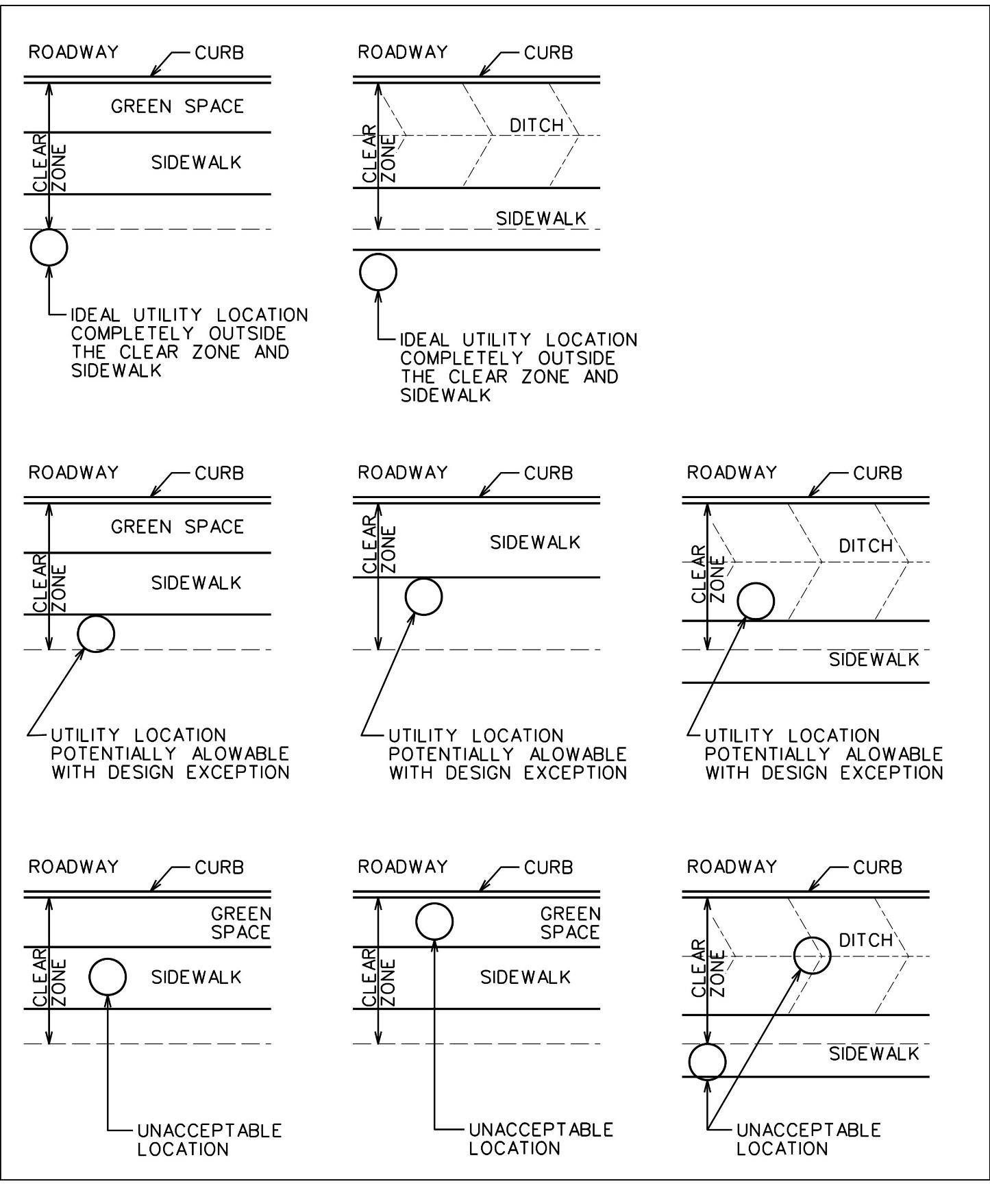
Design Requirements Page | 5-99 9/25/2023 Design Criteria Manual
Figure 5.11-1 - Utility Pole Location Example
5.12 Drainage Design
5.12.1 Storm Water Drainage Design - Storm drainage improvements consisting of storm sewers or open channels shall adequately drain the areas being developed. The design of drainage improvements shall be coordinated to the extent possible with present and probable future improvements so as to form part of an integrated system. Adequate provisions shall be made for the disposal of storm water, in accordance with the specifications and standards of the St. Louis County Department of Transportation, the Metropolitan St. Louis Sewer District (MSD), and any other legally constituted districts and subject to the approval of the Department. No storm water drainage improvements shall be required for a large lot subdivision except where the development is located within MSD's jurisdiction or where the subdivision street or the individual lot access is requested from an existing public street.
1) Drainage Design - All construction details and specifications pertaining to storm water drainage shall be in accordance with the St. Louis County Department of Transportation Standards and MSD requirements unless otherwise noted herein. All design calculations for open and closed drainage systems shall be performed in accordance with MSD's "Rules and Regulations and Engineering Design Requirements for Storm Water Drainage Facilities". A professional engineer's seal and signature shall be required on all plans submitted for approval.
2) Surface Drainage - Sheet flow shall not be allowed over terraces. Berms and / or swales shall be provided to collect the flow at the top or bottom of the terrace and carry it to a drainage structure. Total accumulation inside berms and / or swales shall be a maximum of 4 c.f.s. Critical cross-sections, profiles and hydraulic computations shall be provided for ditches and swales with flows in excess of 1 c.f.s., and creeks with flows in excess of 4 c.f.s.
3) Erosion Control - Erosion control for drainage systems shall be required in swales, ditches, or creeks and at the discharge points of all pipes, when the velocity exceeds 5 feet per second.
Storm water pollution control measures will be required during the construction period of all projects to ensure that mud and other debris are not washed into natural water courses, or new, or previously constructed storm sewers adjacent to properties or road rights-of-way. For land disturbance activities greater than 1 acre in size (including test holes; clearing and grubbing; grading; etc.), a "Stormwater Pollution Prevention Plan (SWPPP)" will be required. For requirements, see St. Louis County's "Sediment and Erosion Control Manual - Model Best Management Practices (BMP) for Land Disturbance"
Design Requirements Page | 5-100 9/25/2023 Design Criteria Manual
4) Site Design Guidance - Long term storm water runoff from projects that disturb an area greater than or equal to one acre, including projects less than one acre that are part of a larger common plan of development or sale, that discharge in to the Municipal Separate Storm Sewer System (MS4), shall ensure that controls are in place that have been designed and implemented to prevent or minimize water quality impacts by reasonably mimicking pre-construction runoff conditions on all affected new development projects and by effectively utilizing water quality strategies and technologies on all affected redevelopment projects, to the maximum extent practicable. Site characteristics shall be assessed at the beginning of the construction / site design phase to ensure adequate planning for storm water program compliance. Design that promotes storm water infiltration within the site shall be emphasized.
5.12.2 Drainage Structure Design - All drainage structures, with the exception of bridges, culvert bridges and, in some cases, culverts, shall be designed for HS20-44 loading. Refer to Section 5.14 for design criteria for bridges. Refer to Section 5.13 for design criteria for culverts and culvert bridges.
1) Modified Sumps - May be required in areas where sidewalk is at back of curb. For construction details refer to Standard Drawing C604.45.
2) Street Inlets - When steep grades or other unusual conditions are encountered, a double-grated inlet structure may be required in lieu of multiple standard inlet structures upstream, in order to eliminate excessive by-pass.
3) Trench Drains - Shall be constructed across driveways serving car wash facilities when on-site pavement slopes towards the driveway and road surface to reduce hazardous situations created by water being carried onto the roadways. The trench drains must be constructed off of the St. Louis County right-of-way on private property.
4) Storm Sewer and Drainage Pipes
a) Pipe Selection - All storm sewer pipes located within the public road right-ofway, shall be reinforced concrete pipe (RCP) Class III minimum, high-density polyethylene (HDPE), polypropylene (PP), or polyvinyl chloride (PVC) storm sewer pipe. High-density polyethylene (HDPE) and PVC storm sewer pipe, from 12 inches to 24 inches in diameter, is allowed in the public road right-of-way, but not under the street pavement. HDPE and PVC plastic end sections are not permitted in the public road right-of-way. Any pipe, conduit, or culvert beneath a highway, road, or street pavement, or with reasonable probability of being so located, shall be RCP Class III minimum; or polypropylene (PP) storm sewer pipe (from 12 inches to 60 inches in diameter); and in no case shall provide for less than HS-20 loading per AASHTO. For other locations, the minimum live load shall be HS-10 loading. Installation of storm sewer systems located on public road right-of-way shall conform to Section 1103.136, Number 11, Item A of the St. Louis County Plumbing Code, "Specifications for Storm SewersInstallation Within Rights-of-Way".
RCP, HDPE, PP or PVC storm sewer pipes, structures, and installation of same for storm sewer systems located on private property, outside of the public road
Design Requirements Page | 5-101 9/25/2023 Design Criteria Manual
right-of-way, shall conform to current Metropolitan St. Louis Sewer District (MSD) Standard Construction Specifications for allowable diameter size and specifications. Installation of storm sewer systems on private property shall also conform to Section 1103.136, Number 11, Item B of the St. Louis County Plumbing Code, "Specifications for Storm Sewers - Installation Outside of Rightsof-Way". A minimum pipe diameter of 12 inches shall be used for storm sewers located on private property.
b) Design Considerations - Normally, pipes shall be sized using the partial full flow design. However, full flow design shall be allowed, provided adequate computations are provided to determine the hydraulic grade line for the pipe and adequate freeboard is provided. For 36-inch diameter pipes or smaller, a minimum 1% grade or 3 feet per second velocity will be required. For pipes larger than 36-inch diameter, the minimum grade shall be the grade establishing a self-cleaning velocity of 3 feet per second. Velocities shall not exceed 25 feet per second where practical.
A minimum pipe diameter of 12 inches shall be used for storm sewers.
Storm sewer pipes may be placed on a curved alignment utilizing alignment radii established by the pipe manufacturer.
c) Construction
i) All pipe, pipe couplings, and accessories shall be unloaded, stockpiled, hauled, distributed, and otherwise handled in a manner which will prevent damage thereto.
ii) Special care shall be taken to lay all pipe to exact grade and line. All pipe, when jointed, shall form a true line of sewer. Any pipe that has a grade or joint disturbed after laying shall be taken up and re-laid.
iii) All pipes shall be laid with the separate sections joined firmly together, with outside laps of circumferential joints pointing upstream, and the centerline of the invert coinciding with the specified alignment of the pipe.
iv) The interior surfaces of all pipes shall be thoroughly cleaned of all foreign matter before being lowered in the trenches and shall be kept clean during laying operations.
v) Joints shall be constructed to attain a watertight joint.
vi) Marking - Each pipe, fitting, or special section shall have markings per AASHTO M 294. Required information shall be plainly and permanently marked on each item. Markings shall include: specification designation, the nominal size, the manufacturer's name, trade name or trademark, plant designation code, and date of manufacture (or appropriate code).
vii) Deflection - HDPE, PVC, and PP pipe maximum deflection (reduction of the barrel base inside diameter) is 5%. Time of measurement shall be not less than 30 days nor more than 60 days following installation.
Design Requirements Page | 5-102 9/25/2023 Design Criteria Manual
5) Reinforced Concrete Storm Sewer Pipes - Reinforced concrete pipe shall conform to the following ASTM Standards and be of the minimum strength designated herein or such higher strength as may be required by the Contract Drawings or Special Provisions.
a) Round Pipe: ASTM C 76, Class III, Wall B.
b) Elliptical Pipe: ASTM C 507, Class HE-III.
c) Arch Culvert Pipe: ASTM C 506, Class A-III.
The class of bedding and the class of pipe shall conform to the requirements of Table 5.12-1 for the applicable overfill height.
Table 5.12-1 - Reinforced Concrete Storm Sewer Pipe
* With imperfect trench
All pipes shall be joined using one of the following flexible gaskets:
• Flat Gaskets - Flat flexible gaskets shall conform to ASTM C 443. They may be cementedto the pipe tongue or spigot. If there is no recess provided forthe gasket, the surface of the tongue shall be cleaned, and rubber adhesive applied. Using quick-drying adhesive, gaskets may be applied ahead of the laying operation or in the plant.
• O-Ring Gaskets - O-Ring or roll-on flexible gaskets shall conform to ASTM C 361, Section 4.10. O-ring gaskets shall be recessed in a groove on the tongue or spigot and confined by the bell or groove after the joint is completed. Roll-on gaskets shall be placed around the tongue or spigot and rolled into position as the joint is assembled. The entire surface of the bell that comes in contact with the rubber gasket shall be well lubricated. Lubricant shall be as recommended by the pipe manufacturer. Only the lubricant supplied by the pipe manufacturer shall be used. Adhesive type cements shall not be used.
6) High Density Polyethylene (HDPE) Storm Sewer Pipe - For the purposes of this section, acceptable HDPE pipe is defined as Type S, double wall (smooth interior, corrugated outer wall), high-density polyethylene (HDPE) pipe. HDPE pipe and fittings shall conform to AASHTO M 294 and ASTM F 2306 with annular corrugations and an
Design Requirements Page | 5-103 9/25/2023 Design Criteria Manual
Class of Pipe Allowable Overfill Heights (feet) Bedding Class C B B1 A* III 1-15 16-18 34-42 IV 1-22 23-27 43-65 100 V 1-27 28-33 65-80 124
integral bell and spigot. The manufacturer of the pipe must participate in the AASHTO / National Transportation Product Evaluation Program (NTPEP). The minimum allowed HDPE pipe diameter in public right-of-way applications is 12 inches, and the maximum allowed diameter for public right-of-way applications is 24 inches and shall conform to current Metropolitan St. Louis Sewer District (MSD) Standard Construction Specifications (Part 2 - Materials of Construction, Section G - Pipe, Item 11). Installation of storm sewer systems located on public road right-of-way shall also conform to Section 1103.136, Number 11, Item A of the St. Louis County Plumbing Code, "Specifications for Storm Sewers - Installation Within Rights-of-Way".
HDPE storm sewer pipes, structures, and installation of same for sewer systems located on private property, outside of the public road right-of-way, shall conform to current Metropolitan St. Louis Sewer District (MSD) Standard Construction Specifications for allowable diameter size and specifications Installation of storm sewer systems on private property shall also conform to Section 1103.136, Number 11, Item B of the St. Louis County Plumbing Code, "Specifications for Storm SewersInstallation Outside of Rights-of-Way". A minimum pipe diameter of 12 inches shall be used for storm sewers located on private property
a) Materials - Virgin material for pipe and fitting production shall be HDPE conforming to the minimum requirements of cell classification 435400C for 12inch and larger diameters, as defined in ASTM D 3350, except that carbon black content shall not exceed 4%.
b) Joints - All HDPE pipe joints shall be gasketed, bell-and-spigot, push-on type conforming to ASTM D 3212, "Standard Specification for Joints for Drain and Sewer Plastic Pipes Using Flexible Elastomeric Seals". Elastomeric seal (gasket) shall have a basic polymer of synthetic rubber conforming to ASTM F 477. Natural rubber gaskets will not be used. Bells shall span over three corrugations. Joints shall be constructed to attain a watertight joint. Since each pipe manufacturer has a different design for push-on joints, gaskets shall be part of a complete pipe section and purchased as such. Gaskets may be factory installed or field installed as recommended by the pipe manufacturer. Lubricant shall be as recommended by the pipe manufacturer.
c) Fittings
i) Fittings shall not reduce or impair the overall integrity or function of the pipeline system.
ii) Fittings shall meet the requirements of AASHTO M 294 and ASTM F 2306.
iii) Fittings may be either molded or fabricated.
iv) Only fittings supplied or recommended by the manufacturer shall be used.
d) Acceptance - Pipe or fittings may be rejected for failure to comply with any requirement of this specification.
Design Requirements Page | 5-104 9/25/2023 Design Criteria Manual
e) Installation - Pipe and fittings should be installed in accordance with St. Louis County specifications; MSD specifications; ASTM D 2321, "Standard Practice for Underground Installation of Thermoplastic Pipe for Sewers and Other GravityFlow Applications"; and the manufacturer's specifications. In the case of a discrepancy between the specifications, the more restrictive requirements shall govern. The engineer should establish the minimum embedment width based on an evaluation of parameters such as pipe stiffness, embedment stiffness, native or in-situ soil, and magnitude of construction and service loads. The minimum cover for 12-inch to 24-inch pipe is 18 inches to the bottom of flexible pavement or the top of rigid pavement. The class of bedding and pipe shall conform to the appropriate ASTM and AASHTO standard specifications for the applicable allowable overfill height. For pipes 24 inches in diameter and smaller, all flexible pipe bedding shall be "MSD 1", as described in the MSD Standard Construction Specifications. The maximum cover depth shall be 30 feet.
Installation of storm sewer systems located on private property, outside of the public road right-of-way, shall conform to current Metropolitan St. Louis Sewer District (MSD) Standard Construction Specifications. A minimum pipe diameter of 12 inches shall be used for storm sewers. The class of bedding and pipe shall conform to the appropriate MSD; ASTM and AASHTO standard specifications for the applicable allowable overfill height. The maximum cover depth shall be 30 feet.
HDPE installations shall not be consolidated by watering (jetting or puddling) and shall not be compacted with hydro hammer type compactors.
f) Embedment Requirements - The method for calculating loads and determining embedment requirements for HDPE sewer pipe shall be in accordance with the appropriate ASTM and AASHTO standard specifications.
g) Post Installation Inspection - Post installation inspection shall be in accordance with St. Louis County Department of Transportation "Standard Specifications for Road and Bridge Construction", Section 730; Missouri Department of Transportation (MoDOT) "Standard Specifications for Highway Construction", Section 730, and the appropriate ASTM and AASHTO standard specifications.
Requirements Page | 5-105 9/25/2023 Design Criteria Manual
Design
7) Polypropylene (PP) Storm Sewer Pipe - For the purposes of this section, acceptable polypropylene (PP) culvert pipe is defined double and triple wall PP culvert pipe intended for use in the construction of culverts, sewers, and similar uses, as described in St. Louis County Department of Transportation's "Standard Specifications for Road and Bridge Construction", Section 1041. All PP culvert pipe, couplings and fittings shall conform to ASTM F 2736 for double wall and ASTM F 2764 for triple wall. The manufacturer of the pipe must participate in the AASHTO / National Transportation Product Evaluation Program (NTPEP). The minimum allowed PP pipe diameter in public right-of-way applications is 12 inches, and the maximum allowed diameter for public right-of-way applications is 60 inches and shall conform to current Metropolitan St. Louis Sewer District (MSD) Standard Construction Specifications (Part 2Materials of Construction, Section G - Pipe, Item 11). Installation of storm sewer systems located on public road right-of-way shall also conform to Section 1103.136, Number 11, Item A of the St. Louis County Plumbing Code, "Specifications for Storm Sewers - Installation Within Rights-of-Way".
All polypropylene culvert pipes, structures, and installation of same for sewer systems located on private property, outside of the public road right-of-way, shall conform to current Metropolitan St. Louis Sewer District (MSD) Standard Construction Specifications for allowable diameter size and specifications. Installation of storm sewer systems on private property shall also conform to Section 1103.136, Number 11, Item B of the St. Louis County Plumbing Code, "Specifications for Storm SewersInstallation Outside of Rights-of-Way". A minimum pipe diameter of 12 inches shall be used for storm sewers located on private property.
a) Materials - Material for polypropylene pipe, coupling and fitting production shall be conforming to the minimum requirements for 12-inch through 60-inch diameters, as defined in ASTM F 2736 and ASTM F 2764, except as noted in Section 1041.3 of the St. Louis County Standard Specifications Manual.
b) Joints - All joints of polypropylene pipe shall provide circumferential and longitudinal strength to maintain the pipe alignment, prevent separation of pipe and prevent infiltration of fill material.
c) Fittings
i) Fittings shall not reduce or impair the overall integrity or function of the pipeline system.
ii) Fittings shall meet the requirements of ASTM F 2736 and ASTM F 2764.
iii) Fittings may be either molded or fabricated.
iv) Only fittings supplied or recommended by the manufacturer shall be used.
d) Acceptance - Pipe or fittings may be rejected for failure to comply with any requirement of this specification.
Design Requirements Page | 5-106 9/25/2023 Design Criteria Manual
e) Installation - Pipe and fittings should be installed in accordance with St. Louis County specifications; MSD specifications; ASTM D 2321, "Standard Practice for Underground Installation of Thermoplastic Pipe for Sewers and Other GravityFlow Applications"; and the manufacturer's specifications. In the case of a discrepancy between the specifications, the more restrictive requirements shall govern. The engineer should establish the minimum embedment width based on an evaluation of parameters such as pipe stiffness, embedment stiffness, native or in-situ soil, and magnitude of construction and service loads. The minimum cover for 12-inch to 60-inch pipe is 18 inches to the bottom of flexible pavement or the top of rigid pavement. The class of bedding and pipe shall conform to the appropriate ASTM and AASHTO standard specifications for the applicable allowable overfill height. For pipes 30 inches in diameter and smaller, all flexible pipe shall be double wall and bedding shall be "MSD 1", as described in the MSD Standard Construction Specifications, and as noted in Section 1041.3.1 of the St. Louis County "Standard Specifications for Road and Bridge Construction" manual. The maximum cover depth shall be 30 feet. For pipes 30 inches in diameter and larger, all flexible pipe shall be triple wall and bedding shall be "MSD 1", as described in theMSD Standard Construction Specifications, and as noted in Section 1041.3.1 of the St. Louis County "Standard Specifications for Road and Bridge Construction" manual. The maximum cover depth shall be 30 feet.
i) Installation of storm sewer systems located on private property, outside of the public road right-of-way, shall conform to current Metropolitan St. Louis Sewer District (MSD) Standard Construction Specifications. A minimum pipe diameter of 12 inches shall be used for storm sewers. The class of bedding and pipe shall conform to the appropriate MSD; ASTM and AASHTO standard specifications for the applicable allowable overfill height. The maximum cover depth shall be 30 feet.
ii) Polypropylene pipe installations shall not be consolidated by watering (jetting or puddling) and shall not be compacted with hydro hammer type compactors.
iii) When flowable fill is used as backfill material use caution. Misalignment or flotation may occur unless added precautions are taken, such as anchoring the pipe or pouring the flowable fill in lifts.
f) Embedment Requirements - The method for calculating loads and determining embedment requirements for polypropylene sewer pipe shall be in accordance with the appropriate ASTM and AASHTO standard specifications and manufacturer's guidelines.
g) Post Installation Inspection - Post installation inspection shall be in accordance with the appropriate ASTM and AASHTO standard specifications and manufacturer's guidelines. Pipe deflection is to be tested within 30 days of installation by pulling a mandrel through the installed pipe. Testing 10% of the overall project should provide a reasonable indication of installation quality. Recommended mandrel settings shall be in accordance with manufacturer's guidelines for the pipe size and wall type installed. For sanitary installations,
Design Requirements Page | 5-107 9/25/2023 Design Criteria Manual
after sanitary pipe has been installed, sections of pipe shall be tested for leakage. Pipe shall be tested by water infiltration or by air pressure. The test method must be in accordance with ASTM F 2487 for water and ASTM F 1417 or ASTM C 1103 for air.
8) Polyvinyl Chloride (PVC) Storm Sewer Pipe - For the purposes of this section, acceptable PVC pipe is defined as, double wall (smooth interior, corrugated outer wall), Polyvinyl Chloride (PVC) gravity flow storm drainage pipe in nominal diameters 12 inches through 24 inches. PVC stormwater sewer pipe and fittings shall conform to AASHTO and ASTM specifications with annular corrugations and an integral bell and spigot. The manufacturer of the pipe must participate in the AASHTO / National Transportation Product Evaluation Program (NTPEP). The minimum allowed pipe diameter in public right-of-way applications is twelve 12 inches, and the maximum allowed diameter for public right-of-way applications is 24 inches and shall conform to current Metropolitan St. Louis Sewer District (MSD) Standard Construction Specifications (Part 2 - Materials of Construction,Section G - Pipe, Item 8). Installation of storm sewer systems located on public road right-of-way shall also conform to Section 1103.136, Number 11, Item A of the St. Louis County Plumbing Code, "Specifications for Storm Sewers - Installation Within Rights-of-Way".
PVC storm sewer pipes, structures, and installation of same for sewer systems located on private property, outside of the public road right-of-way, shall conform to current Metropolitan St. Louis Sewer District (MSD) Standard Construction Specifications for allowable diameter size and specifications. Installation of storm sewer systems on private property shall also conform to as well as Section 1103.136, Number 11, Item B of the St. Louis County Plumbing Code, "Specifications for Storm SewersInstallation Outside of Rights-of-Way". A minimum pipe diameter of 12 inches shall be used for storm sewers located on private property.
a) Materials - All PVC pipe and fittings shall be manufactured and tested in accordance with the appropriate ASTM and AASHTO standard specifications. All fittings shall be compatible with the pipe to which they are attached.
b) Joints - All PVC pipe joints shall be gasketed, bell-and-spigot, push-on type conforming to ASTM D 3212, "Standard Specification for Joints for Drain and Sewer Plastic Pipes Using Flexible Elastomeric Seals". Elastomeric seal (gasket) shall have a basic polymer of synthetic rubber conforming to ASTM F 477. Natural rubber gaskets will not be used. Bells shall span over three corrugations. Joints shall be constructed to attain a watertight joint. Since each pipe manufacturer has a different design for push-on joints, gaskets shall be part of a complete pipe section and purchased as such. Gaskets may be factory installed or field installed as recommended by the pipe manufacturer. Lubricant shall be as recommended by the pipe manufacturer.
Design Requirements Page | 5-108 9/25/2023 Design Criteria Manual
c) Fittings
i) Fittings shall not reduce or impair the overall integrity or function of the pipeline system.
ii) Fittings shall meet the requirements of AASHTO M 294 and ASTM F 2306.
iii) Fittings may be either molded or fabricated.
iv) Only fittings supplied or recommended by the manufacturer shall be used.
d) Acceptance - Pipe or fittings may be rejected for failure to comply with any requirement of this specification.
e) Installation - Pipe and fittings should be installed in accordance with St. Louis County specifications; MSD specifications; ASTM D 2321, "Standard Practice for Underground Installation of Thermoplastic Pipe for Sewers and Other GravityFlow Applications"; and the manufacturer's specifications. In the case of a discrepancy between the specifications, the more restrictive requirements shall govern. The engineer should establish the minimum embedment width based on an evaluation of parameters such as pipe stiffness, embedment stiffness, native or in-situ soil, and magnitude of construction and service loads. The minimum cover for 12-inch to 24-inch pipe is 18 inches to the bottom of flexible pavement or the top of rigid pavement. The class of bedding and pipe shall conform to the appropriate ASTM and AASHTO standard specifications for the applicable allowable overfill height. For pipes 24 inches in diameter and smaller, all flexible pipe bedding shall be "MSD 1", as described in the MSD Standard Construction Specifications. The maximum cover depth shall be 30 feet.
Installation of storm sewer systems located on private property, outside of the public road right-of-way, shall conform to current Metropolitan St. Louis Sewer District (MSD) Standard Construction Specifications. A minimum pipe diameter of 12 inches shall be used for storm sewers. The class of bedding and pipe shall conform to the appropriate MSD; ASTM and AASHTO standard specifications for the applicable allowable overfill height. The maximum cover depth shall be 30 feet.
PVC installations shall not be consolidated by watering (jetting or puddling) and shall not be compacted with hydro hammer type compactors.
f) Embedment Requirements - The method for calculating loads and determining embedment requirements for PVC sewer pipe shall be in accordance with the appropriate ASTM and AASHTO standard specifications.
Design Requirements Page | 5-109 9/25/2023 Design Criteria Manual
g) Post Installation Inspection - Post installation inspection shall be in accordance with St. Louis County Department of Transportation's "Standard Specifications for Road and Bridge Construction", Section 728; Missouri Department of Transportation (MoDOT) "Standard Specifications for Highway Construction", Section 730; and the appropriate ASTM and AASHTO standard specifications.
9) Bridges - Bridges in flood plain areas shall be designed on a 100-year storm frequency and shall provide a minimum of 1 foot of freeboard between the bottom of the superstructure and the high water elevation. Bridges in non-flood plain areas shall be designed on a 100-year storm frequency and shall provide a minimum of 2 feet of freeboard between the bottom of the superstructure and the high water elevation.
10) Culverts - Crossroad culverts, not at low points, shall be designed for the 15 years20 Minute storm event with entrance control and a minimum of 2 feet of freeboard at the shoulder line. Culverts, at or near low points in flood plains, shall be designed on a storm frequency of 100 years with entrance control and minimum of 2 feet of freeboard at the shoulder line. Culverts, at or near low points not in flood plains, shall be designed on a storm frequency of 50 years with entrance control and a minimum of 2 feet of freeboard at the shoulder line. Refer to the U.S. Department of Transportation Hydraulic Engineering Circular No. 5, entitled "Hydraulic Charts for the Selection of Highway Culverts". All crossroad culverts shall be RCP storm sewer pipe, precast or poured in-place reinforced concrete. Private driveway culverts may be RCP, HDPE, or PVC storm sewer pipe.
Precast concrete box sections will be considered and may be approved. As a minimum, they shall meet the requirements of ASTM C 1433, "Standard Specification for Precast Reinforced Concrete Box Sections for Culverts, Storm Drains and Sewers". Modifications to the standards may be required in cases of spans greater than 10 feet. The specific box section and type of joint shall be as approved by the Department.
11) Roadways - When a watercourse exists or is proposed approximately parallel to or near an existing or proposed roadway, the low shoulder elevation of the roadway shall be established from the high water elevation with a minimum of 2 feet of freeboard. In certain (levee-protected) areas, this requirement may be reduced by permission from the Department.
5.12.3 Sump Pump Discharge
1) Drain to a Street Inlet - Line shall be placed in the one-foot grass area behind the sidewalk and discharge into the street inlet three (3') feet below the top of the inlet.
2) Drain to a Field Inlet in Backyard
a) Line shall connect to a collector line in the backyard located in an easement. The collector line shall discharge into the field inlet three (3') feet below the top of the structure. Within the boundaries of the Metropolitan St. Louis Sewer District (MSD), the connection shall be made in accordance with the requirements of MSD.
b) Line may discharge into an open swale through adjacent backyards to the field
Design Requirements Page | 5-110 9/25/2023 Design Criteria Manual
inlet. The swale must be located in an easement dedicated to Subdivision Trustees for sump pump drainage purposes.
3) Drain to Natural Discharge - Line may discharge in a natural discharge point located on the same property.
4) Drain to Common Ground - Line may discharge on the same property where drainage continues to common ground without traversing adjacent lots.
5) Special Conditions
a) In all cases, sump pump discharge lines shall leave the foundation of the building at an elevation that allows gravity flow to a discharge point.
b) Lines shall not cross under roadways.
c) Lines shall not discharge on sidewalks or at roadway curbs.
d) Lines shall not connect directly to a storm sewer pipe.
e) Lines in right-of-way shall not be maintained by St. Louis County but shall be the responsibility of the property owner.
f) Special Use Permits for all lines in right-of-way are required.
g) Collector line runs are recommended where lines are parallel and draining to the same discharge point.
h) Connection to structures shall be grouted and sealed per St. Louis County Standards or the Metropolitan St. Louis Sewer District (MSD) requirements.
i) A hold harmless agreement is required to indemnify and hold harmless the County, its agents, officers, and employees, from any and all claims, lawsuits, and expenses, including attorney's fees and court costs, made, brought, or incurred for injuries to persons or property caused by the work contemplated in connection with sump pump discharge lines.
j) All easements dedicated for use by sump pumps shall be the maintenance responsibility of the Subdivision Trustees or individual property owner and not the responsibility of St. Louis County.
k) In new subdivisions, it is recommended that the Consultant Engineer design the discharge lines into the approved subdivision plans, eliminating the need for separate approval and issuance of a separate Special Use Permit (SUP).
Design Requirements Page | 5-111 9/25/2023 Design Criteria Manual
5.12.4 Miscellaneous Storm Water Requirements
1) A land disturbance permit is required prior to any land disturbance (clearing and grubbing, grading, etc.) on the site. No significant change in watersheds as determined by the Department and the Metropolitan St. Louis Sewer District (MSD) shall be permitted.
2) Interim stormwater drainage control in the form of siltation control measures are required, in compliance with St. Louis County's Land Disturbance Code.
3) Submit to the Planning Commission an engineering plan, approved by the Department of Transportation, showing that adequate handling of the stormwater drainage of the site is provided.
4) The developer is required to provide adequate stormwater systems in accordance with St. Louis County Standards and the requirements of MSD where applicable.
5) All stormwater shall be discharged at an adequate natural discharge point. Sinkholes are not considered adequate discharge points.
6) Ponds and/or lakes will be dewatered at a rate not to exceed a 15-year 20-minute design storm to protect against erosion and siltation damage to adjacent properties and roads.
7) If required by ordinance and prior to any grading of a site, a bond shall be posted in an amount determined by the Department to assure maintenance of the quality of detention areas on adjoining or downstream property. Said bond shall remain in effect through the construction phases and until eighteen (18) months after the completion of the last structure on the site.
8) Foundation and building permits will be withheld, by the Department of Public Works, for any lot that adjoins the common ground and/or detention basin areas until a written certification is received, from the Department, stating that the areas have been graded in accordance with the approved plans.
9) New flood management projects located within the County are assessed for impacts on water quality. Existing projects are assessed for incorporation of additional water quality protection devices or practices, where feasible. Flood management projects in the plan area can include: regional storm water control (retention basins, detention basins); flood control levees and associated pump stations; storm water drainage conveyance capacity improvements; bridges and culverts; projects involving land buyouts; and designated uses of flood plain land.
Storm water management projects in both development and re-development are assessed for water quality impact, according to MSD's "Rules and Regulations and Engineering Design Requirements for Storm Water Drainage Facilities", which address the "Storm Water Management Plan" water quality requirements under Minimum Control Measure #5 located in the St. Louis County, "Phase II Storm Water Management Plan" and Chapter 10 of the St. Louis County "Operations and Maintenance Manual". Projects within designated levee districts, such as MonarchChesterfield, Earth City and Riverport are based on the "Storm Water Master Plan" for
Design Requirements Page | 5-112 9/25/2023 Design Criteria Manual
these districts. All flood management projects involving channel modification will also be assessed for aquatic and water quality impacts through the Corps of Engineers 404 permit and MDNR 401 water quality certification process.
5.13 Culvert and Culvert Bridge Design - The following is an outline of minimum design requirements for culverts and culvert bridges built within theSt. Louis Countyright-of-way. Castin-place reinforced concrete box culvert and box culvert bridge design shall generally be in accordance with the Missouri Department of Transportation (MoDOT) Engineering Policy Guide (EPG), Section 751.8, "LRFD Concrete Box Culverts".
The use of corrugated metal and corrugated aluminum culverts and culvert bridges is not permitted except by the direct written authorityof the Director or his designee For culvert and culvertbridgedesignitemsnotspecifically coveredby MoDOT,theAmerican Association of State Highway and Transportation Officials (AASHTO) LRFD Bridge Design Specifications, 4th Edition, with 2008 Interims shall be used as design specifications. Newer versions of AASHTO specifications may be used with written consent from the Director or his designee.
Thedesigninformationintheabovementionedreferencesshallbesupplementedby the following requirements:
Loads and Load Distribution - Load rating and permit vehicles shall be as shown in Section 5.14, "Bridge Structure Design".
5.14 Bridge Structure Design - The following is an outline of minimum design requirements for bridges built within the St Louis County right-of-way Bridge design shall generally be in accordance with the Missouri Department of Transportation (MoDOT) Engineering Policy Guide (EPG), Section 751, “LRFD Bridge Design Guidelines”, unless otherwise noted.
Before any detailed design is undertaken for a bridge structure to be maintained by St. Louis County, the design consultant must attend a scoping meeting with the Department in order to identify project-specific issues that must be addressed.
Thedesigninformationintheabovementionedreferenceshallbesupplementedby the following requirements:
5.14.1 Load Rating Vehicles - New structures shall be rated according to AASHTO’s Manual for Bridge Evaluation, 2nd Edition, 2011 as indicated below.
Nominal Live Loads are grouped into three categories:
1) Design Load: HL-93 Design Load from AASHTO LRFD Design Specifications
2) Legal Loads: AASHTO Legal Loads or State Legal Loads
Design Requirements Page | 5-113 9/25/2023
Manual
Design Criteria


Design Requirements Page | 5-114 9/25/2023 Design Criteria Manual
AASHTO Type 3 Unit:
AASHTO Type 3S2 Unit:
AASHTO Type 3-3 Unit: 8 Kip Axle 32 Kip Axle 14’ -0” 32 Kip Axle 14’ -0” to 30’-0” 10 Kip Axle 15.5 Kip Axle 15.5 Kip Axle 15.5 Kip Axle 15.5 Kip Axle 11’ -0” 22’-0” 4’-0” 4’-0” 12 Kip Axle 12 Kip Axle 14 Kip Axle 14 Kip Axle 12 Kip Axle 15.0’ 15.0’ 4.0’ 4.0’ 16 Kip Axle 16.0
a)
b)
c)


Design Requirements Page | 5-115 9/25/2023 Design Criteria Manual
d) Missouri State Legal Load-H20:
e) Missouri State Legal Load-HS20:
8 Kip Axle 32 Kip Axle 14’ -0” 32 Kip Axle 14’ -0” to 30’-0” 8 Kip Axle 32 Kip Axle 14’ -0” 10 Kip Axle 40 Kip Axle 14’ -0” 40 Kip Axle 14’ -0” to 30’-0”
f) Missouri State Legal Load-HS25:
3) Permit Loads: Actual Permit Trucks:
Design Requirements Page | 5-116 9/25/2023 Design Criteria Manual
Vehicle and Weight Illustration-Axle Weights TANDEM 33.6 Ton 67.2 Kip Single Truck TRIAXLE 44.8 Ton 89.6 Kip Single Truck H20 LEGAL 20 Ton 40 Kip Single Truck T45 45 Ton 90 Kip Single Truck 3S2 36.64 Ton 73.28 Kip Double Truck MO5 36.64 Ton 73.28 Kip Double Truck 22.4 kip 22.4 kip 22.4 kip 12'-0" 4'-0" 22.4 kip 22.4 kip 22.4 kip 10'-0" 4'-0" 4'-0" 22.4 kip 8 kip 16 kip 16 kip 12'-1 1/4" 3'-9 1/2" 16 kip 16 kip 16 kip 16 kip 12'-0" 3'-9 1/2" 23'-5" 3'-9 1/2" 9.28 kip 16 kip 16 kip 16 kip 16 kip 12'-0" 3'-9 1/2" 3'-9 1/2" 23'-5" 9.28 kip 18 kip 24 kip 24 kip 12'-0" 4'-0" 4'-0" 24 kip
5.15 Retaining Wall Design - All walls built within St. Louis County maintained right-of-way shall be subject to the review of the Department of Transportation Additionally, the following walls shall also be subject to the Department’s design criteria and review:
• Retaining walls supporting the roadway fill of a St. Louis County maintained road, provided that the horizontal distance from the right-of-way line to the fill face of wall is less than 1.75 times the vertical grade difference between the ground elevation at the right-of-way line and thebottom of footing (not bottom of shear key) elevation (see Figure 5.15-1).
• Retaining walls supporting roadway cuts adjacent to St. Louis County maintained roads, provided that the distance between the right-of-way line and face of the wall is less than the exposed wall height.
All retaining walls built for the purpose of retaining roadway fill shall be constructed of cast-inplace reinforced concrete unless specifically authorized by the Director or his designee. Retaining walls built in roadway cuts may be either cast-in-place reinforced concrete or mechanically stabilized earth (MSE).
Designers should follow the Missouri Department of Transportation (MoDOT) Engineering Policy Guide (EPG) for design guidance and detailing, except where noted otherwise. Because LRFD retaining wall design items are not yet covered by the EPG, the American Association of State Highway and Transportation Officials (AASHTO) LRFD Bridge Design Specifications, 4th Edition, with 2008 Interims shall be used as design specifications. Newer versions of AASHTO specifications may be used with written consent from the Director or his designee.
The design information in the above mentioned reference shall be supplemented by the following requirements:
For all walls under St. Louis County Department of Transportation review with grade differences of four feet (4') or more, a 5'-0" chain-link fence must be indicated at the top of the wall, and St. Louis County Standard Drawing C607.12 must be included or referenced with the plans
Consideration shall be given to written requests concerning the use of other guards or railings
All such guards or railings must be a minimum of forty-two inches (42") in height to the top of the top rail Wrought Iron railings will not be approved for walls to be maintained by St. Louis County
All retaining walls located outside of the public road right- of-way on private property, shall be privately maintained and shall conform to the guard requirements of "Title XI SLCRO 1974"' as amended, "Public Works and Building Regulations", Chapters 1115, Sections 105.2.5, 1012.3, 1012.6 and 1806.2 (St. Louis County Ordinance 22,314, Approved May 18, 2005).
For subdivision and permit projects, please refer to the list on the following page of general notes for retaining wall construction.
5.15.1 Railroad Tie Retaining Walls - Railroad tie walls will not be permitted as a means of retaining roadway fill or cuts adjacent to St. Louis County maintained roads. Double or multiple tiered walls shall not be permitted adjacent to a street right-of-way. Where lawn terracing is necessary above the retaining wall, it shall be limited to a 3:1 or flatter slope.
Railroad tie walls may not be utilized for erosion control or bank protection. Railroad tie walls should not be constructed where they are in conflict with stormwater drainage, such as in swales or tops of terraces, etc. Railroad tie walls are not permitted within the flood plain or in detention areas. The responsibility for maintenance of retaining walls located outside of public
Design Requirements Page | 5-117 9/25/2023 Design Criteria Manual
right-of-way lies with the subdivision trustees or the individual property owners and not the Department.
Railroad tie retaining walls are an acceptable construction method for stabilizing vertical cut and fill areas in areas other than described above. Alternate soil retention system that utilize geogrid soil reinforcement along with modular concrete retaining wall units (e.g. Keystone® , Versa-Lok®, etc.) are encouraged due lower long term maintenance costs. Final design of all retaining wall systems shall be based upon adequate site investigation and design by a qualified Engineer.
5.15.2 General Notes for Retaining Wall Construction - The following notes shall be used for Subdivision and Permit Projects:
1) St. Louis County Class B Concrete shall be used for all retaining walls with f’c equal to 3,500 psi or less. St. Louis County Class B-1 Concrete shall be used for all retaining walls with f’c equal to 4,000 psi or less. St. Louis County Class B-2 Concrete shall be used for all retaining walls with f’c greater than 4,000 psi. All materials, proportioning, air-entraining, mixing, transporting, and slump of the concrete shall be in accordance with Section 501 of the current St. Louis County Standard Specifications for Road and Bridge Construction.
2) All reinforcing steel shall conform to ASTM Specification A615, Grade 60.
3) All materials and workmanship for the wall shall conform to the most current edition of the St. Louis County Standard Specifications for Road and Bridge Construction.
4) Pouring retaining wall footings without formwork will not be permitted Pouring retaining wall shear keys without formwork will be permitted unless noted otherwise on the plans.
5) Plastic protected bar supports are required wherever the concrete surface is exposed. Bar supports for reinforcement are to be of the earth-bearing base type. Bar supports used to support the upper mat of steel in the footing shall be full height, providing the proper clearances. Standees resting on the lower mat of bars will not be permitted.
6) Splices in longitudinal reinforcement shall be as required per AASHTO Bar splices will not be permitted on other bars unless explicitly shown on the plans.
7) Placing form oil or other release agent on the forms prior to placement of the reinforcing steel is required.
8) Triangular molding, having 0.75-inch width on each of the two (2) form sides, shall be used to bevel all exposed edges on the structure.
9) Curing of the concrete shall be as per the most current edition of the St. Louis County Standard Specifications for Road and Bridge Construction.
10) Where earth backfill is specified, it shall be placed and compacted in accordance with the most current edition of the St. Louis County Standard Specifications for Road and Bridge Construction.
Design Requirements Page | 5-118 9/25/2023 Design Criteria Manual
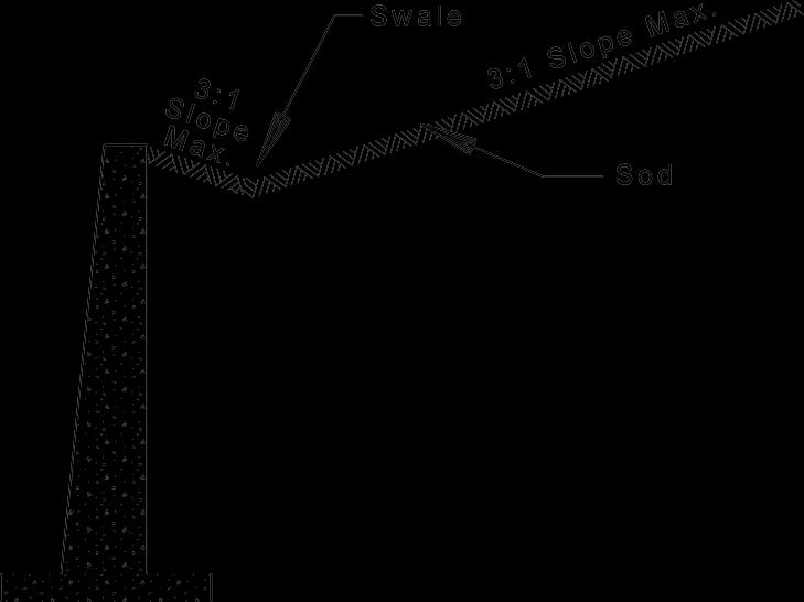


Design Requirements Page | 5-119 9/25/2023 Design Criteria Manual
Figure 5.15-1
5.16 Traffic Signal Design - The purpose of this chapter is to provide instruction for practices and standards used in the design of St. Louis County traffic signals. This chapter describes typical practices for new or modified traffic signal control system installations countywide. This chapter shall be used in conjunction with applicable criteria stated elsewhere in this manual, Standard Specifications for Road and Bridge Construction, Standard Drawings, Special Provisions, and other current design policies. Deviations from these guidelines shall be based on informed engineering decisions approved by St Louis County.
5.16.1 Definition of Traffic Signal - Traffic control devices utilizing strategically placed signs and electric powered lighted symbols used to assign coordinated right of way movements and eliminate conflicts between motorists, cyclists, and pedestrians. Traffic control devices additionally used to heighten awareness of significant changes in roadway conditions and /or regulations.
5.16.2 Types of Traffic Signals
1) Intersection - Assigns right of way to non-conflicting movements of traffic on one street until a determination is made to reassign the right of way to non-conflicting movements of traffic on the intersecting street.
2) Fire Station - To reassign the right of way from the traffic on the street to a fire station entrance, to provide immediate and safe egress to vehicles from the fire station to respond to emergency calls.
3) Pedestrian - To reassign the right of way from the vehicles on the street to a designated location for pedestrians to safely cross the street.
4) Flasher - To heighten awareness of significant changes in roadway conditions and/or regulations that could adversely affect the safety of motorists, cyclists, and pedestrians.
5.16.3 Traffic Signal Warrants and Justification - The St. Louis County Department of Transportation requires the proposed signal to meet at least one signal warrant in the MUTCD. A signal warrant is a minimum condition for which a signal may be installed. However, satisfying a warrant doesnot mandate the installation of a traffic signal. A warranting condition indicates that an engineering study is required to determine whether the signal is justified.
An engineering study is required for every proposed traffic signal. Typically, the study includes intersection capacity analysis to determine the level-of-service (LOS) for the AM and PM peak hour traffic condition. Depending upon the location and circumstances, an LOS analysis may be required by the Department for other periods as well. Prior to signal design, the Department's Transportation Planning Division must approve the engineering study.
A queue analysis may be required to determine the appropriate lane configuration and length for the intersection. Based on the results of the engineering study, the appropriate number of lanes, length of turning lanes, and signal phasing will be determined. Close coordination with the Highway Planning Division is required throughout the engineering study to develop the optimum intersection configuration.
Design Requirements Page | 5-120 9/25/2023 Design Criteria Manual
Signal spacing should be considered during the development of a traffic signal design. Signalized intersections should be located to maintain progression of traffic along arterial streets. This normally entails relatively uniform spacing and sufficient distances between signals to allow vehicles to travel at reasonable speeds. The optimal spacing is a function of the cycle length and the progression speed of traffic along the major street. The proposed signalized intersection shall be based on an arterial progression analysis and provide acceptable green band and level of service.
5.16.4 Developer Responsibilities - If determined necessary by the Department, the costs of their design, installation and materials shall be the responsibility of the developer, property owner, church, or school.
If traffic signals or modifications to existing traffic signal facilities are required as part of a development, the developer shall be required to provide equipment and install the traffic signal as directed by the Department. The traffic signal installation, including all conduit detector loops, bases, boxes, power supply facilities, cable / conduit connections to Ameren Missouri, and interconnect, shall be located entirely within the public road right-of-way, a roadway maintenance easement, or a Permanent Traffic Signal Easement.
The traffic signal materials and equipment shall be ordered as soon as approvals are received in order to avoid lengthy delays. Delays caused by delivery of materials and equipment shall not constitute a cause to allow occupancy prior to completion of road improvements.
If traffic signals are not warranted at the time of initial development, the developer may be required to provide a cash escrow or irrevocable letter of credit for future traffic signals or a reasonable share of costs for future traffic signals based upon a percentage of traffic volume generated by the development as applied to the intersection to be signalized as approved by the Department. This escrow or letter of credit shall be deposited prior to issuance of building permits.
In addition, the developer may also be required by the Department to install underground conduit and pull boxes for future traffic signals if new driveway approaches are constructed or modifications to existing street intersections are required.
Installation of interconnect conduit and pull boxes for connection to future or existing signals will be required and shall be installed as directed by the Department.
When pedestrian signals are determined to be warranted by the Department, the costs of their design, installation and materials shall be the responsibility of the developer, property owner, church, or school
When fire station signals are determined to be warranted by the Department, the costs of their design, installation and materials shall be the responsibility of the developer or fire district.
Design Requirements Page | 5-121 9/25/2023 Design Criteria Manual
5.16.5 Standard References - The following are standard reference documents for the design of traffic signals:
1) Plans shall be prepared in accordance with the St. Louis County Department of Transportation's active traffic signal design standards.
2) Equipment, materials, construction requirements and installation procedures shall meet or exceed the most recent version of St. Louis County Standard Specifications for Road and Bridge Construction Division 900 - Section 904 and St. Louis County Standard Drawings - Traffic Signal Details, unless noted otherwise in the construction documents, or superseded by direction in this section.
3) All new or upgraded signal installations shall conform to the requirements in Part IV of the MUTCD.
5.16.6 Special Agreements - Special agreements, when applicable, must be executed in response to an entity’s request to install special equipment relating to the traffic signal. These agreements include lighting, street landscape, signal priority control, and red light photo enforcement.
5.16.7 Survey Requirements
1) Existing Improvements, Underground and Overhead Utilities, and Sewers - All signal plans shall show the location of existing improvements, underground and overhead utilities, and sewers as taken from observed evidence together with plans and markings obtained from utility companies or other appropriate sources. The designer should contact the Department’s Division of Operations (Signal Section) at (314) 615-0215 for marking the location of St. Louis County’s underground traffic signal facilities. Overhead utilities shall be verified for minimum clearance to the proposed signal equipment. When potential conflicts with utilities exist, additional right-of-way or easement is required to avoid the utility. If this is not feasible, the utility company should be contacted regarding the relocation of the utility.
The type of pavement shall be noted on the plan. Joints in concrete pavement shall be shown on the plan to assist in determining induction detector loop placement. If possible, avoid placing detector loops and leads across pavement joints.
The Department's Traffic Signal Symbols, Design Criteria Manual Supplemental Drawing 5.6, shall be used to depict all traffic signal equipment on the plan.
2) Rights-of-Way and Easements - All signal plans shall show existing and proposed rights-of-way and easements for locating traffic signal equipment. All traffic signal equipment shall be in public right-of-way or in a permanent easement which is in the name of the County and specifically allows for the placement and maintenance of traffic signal equipment. This would include power supply equipment, loop detectors, conduit, poles, mast arms, posts, pull boxes, traffic controller cabinets, bases, and cameras.
There shall be at least five feet of clearance beyond any traffic signal equipment to the edge of the easement or right-of-way to allow for working room.
Design Requirements Page | 5-122 9/25/2023 Design Criteria Manual
5.16.8
Crosswalks, Curb Ramps, Pedestrian Signal
Heads and
Push Buttons
Signalized crosswalks shall be provided at all intersections where there is pedestrian activity or sidewalks. These facilities shall be designed in accordance with Section 5.7 Intersection Geometric Design and section 5.8 Pedestrian Facility Design
Curb ramps, pedestrian signal heads and push buttons are required where a crosswalk is marked at a signalized intersection. Crosswalks should be ten feet wide and located as close as possible to the intersection. This improves pedestrian visibility for the turning traffic. In order to maximize the overall signal efficiency, crosswalks crossing a major street may be reduced to one crossing if the side street operation is split phased. The following factors should also be considered when designing crosswalks, curb ramps, and stop lines:
• Align crosswalks and stop lines as close to perpendicular to the approach traffic lanes as possible.
• Center the curb ramps in the crosswalks.
• Minimize pedestrian exposure to turning vehicles.
• Ensure that pedestrians waiting at the curb ramps are readily visible to drivers of approaching and turning vehicles.
• Minimize pedestrian crossing distance and crossing time.
• Clarify and simplify the pedestrian's crossing route.
Pedestrian signal heads should be placed to maximize the visibility of the signal to pedestrians using the crosswalk for which the signal head provides indications.
Pedestrian push buttons should be located in the normal travel path of the pedestrian. Push buttons should be located within five feet of the crosswalk line and within six feet of the curb. The unobstructed horizontal side reach to the push button shall not exceed 10 inches.
In addition, push buttons shall be located adjacent to a landing area. Poles, pull boxes, and other obstructions should not be located in the curb ramps or in the landing areas.
5.16.9 Signal Indications and Layouts - Post top mounted signals are to be used only where the Department determines it is not physically suitable to install mast arms.
The face of pole/post shall have a horizontal clearance of not less than three feet from the face of curb, island, median or edge of pavement.
Far left indications are required for County signal installations wherever left turns are permitted. However, this does not apply for left turns into residential entrances.
The intersecting approach at T-type intersections should include left and right arrows, provided no pedestrian conflict exists.
Straight thru arrow indications on street approaches shall only be used with Department approval.
Design Requirements Page | 5-123 9/25/2023 Design Criteria Manual
Flashing yellow arrow indications on street approaches shall be used for left turn movements when there is a lane dedicated lane for left turn movements only
Back plates shall be required for all vehicular signal heads.
Optically limiting signal faces may be required where the driver at an intersection may be influenced by the indications at the next closely situated intersection. Optically limiting signal faces should be considered when signalized intersections are 300 feet apart or closer.
Optically limiting signal faces may be required at a skewed intersection where drivers in opposing lanes may be influenced by the same signal face.
Signal heads for emergency signals shall be mounted horizontally when located on the mast arm.
5.16.10 Vehicle Detection -
Stop bar and advance detection is required on all signalized approaches at all intersection signals, unless directed otherwise by County. If both stop bar and advance detection is not feasible Department shall be contacted for guidance.
Advance detection is required at mid-block pedestrian signals and at intersection signals in through lanes on major streets and, in some cases, on side streets if volume is high, or grades are steep.
(1) 85th percentile speed or 5 MPH greater than the posted speed limit.
The Department requires induction loop detectors for vehicle detection. Other types of detection should not be considered. Under conditions where a bridge deck or railroad track conflict exists, and would prohibit the installation of induction loops, the Department shall be contacted for guidance and authorization of alternative detection equipment.
Design Requirements Page | 5-124 9/25/2023 Design Criteria Manual
Vehicle Speed (MPH) (1) Distance from Stop Line to front of 6' x 6' Loop (Feet) Distance Traveled in Extension Interval of 6 Seconds 1.47 x MPH x 6 Seconds (Feet) 30 250-270 264 35 300-320 309 40 340-360 353 45 390-410 397 50 430-450 441
Table 5.16-1 - Advance Detection
Stop line detection generally consists of multiple quadrupole loops configured to provide a lane detection area 6' wide by approximately 40' long.
In concrete pavement, multiple loops should be placed end to end and centered in the lane to provide a 6' wide by approximately 40' long lane detection area. Loops should be 6' wide, but the length of each loop is determined by the size of each individual pavement slab. Typically the loops are installed one foot from the transverse pavement joint. Sawed slots that construct the loops should not cross transverse pavement joints and shall have a 1' minimum clearance from the sawed slots constructing other loops.
In asphalt pavement, two 6' wide by 20' long loops should be placed end to end and centered in the lane to provide a 6' wide by 40' long lane detection area. Sawed slots constructing the loops shall have a 1' minimum clearance from sawed slots constructing other loops.
Stop line detection should also be provided in the dedicated right turn lane when right turn overlap phasing is proposed.
In instances where existing detection will be disrupted due to the improvements being proposed or is anticipated to be disrupted due to construction activity, the designer shall contact the Department regarding requirements for temporary detection.
5.16.11 Interconnect – As all County traffic signals are interconnected, traffic signal interconnect shall be required The signal designer should coordinate with the Department to determine if new interconnect is needed or if modifications to ethe existing interconnect is necessary. The signal designer should also coordinate with the Department to determine the type of interconnect that is the most feasible. f
It will be necessary to provide separate interconnect layout plans to illustrate any additions or modifications to the County’s interconnect system Location of conduit, pull boxes, and cables, termination cabinets and other facilities shall be included.
Interconnect cables and equipment shall be compatible with existing and proposed County Intelligent Transportation System (ITS) networks. Modifications to, or replacement of existing signal equipment may be required for ITS functionality.
Interconnect conduit shall have 17"W x 30"L x 26"H (Min. H) preformed pull boxes spaced at intervals no greater than 400 feet.
Interconnect cables shall terminate at controller cabinets or fiber optic termination cabinets only. Cable splices will not be allowed.
Interconnect conduit and cable should be incorporated into the signal pull box and conduit facilities for connection at the designated signal controller cabinets.
Design Requirements Page | 5-125 9/25/2023 Design Criteria Manual
5.16.12 Pan Tilt Zoom (PTZ) Video Surveillance Camera - A PTZ camera is required at all intersection traffic signal installations and reconstruction projects, unless determined otherwise by the Department.
5.16.13 Pull Boxes and Conduit Sizes - A single concrete pull box is required adjacent to each signal base. A double concrete pull box is required adjacent to the controller base, in the island nearest to the controller base and wherever the number of conductors entering a pull box is greater than 100. However, a single concrete pull box may be installed adjacent to a controller cabinet at midblock and fire station signals. Where a pull box is required to be installed in the pedestrian path, a Reinforced Plastic Concrete pull box w/ground rod shall be used in place of a single concrete pull box. Where a Reinforced Plastic Concrete pull box is required in place of a single concrete pull dox, the size of said Reinforced Plastic Concrete pull box shall be approved by the Department.
The preferred location of the concrete pull box is no further than 10 feet from the signal or controller base and no further than 6 feet from the face of island when practical. The placement of concrete pull boxes in sidewalk, or curb ramps or cut-throughs should be avoided when possible.
Reinforced Plastic Concrete pull boxes may be installed for interconnect systems and advance loop detectors. Unlike concrete pull boxes, the sidewalk is the preferred location for RPC pull boxes.
Conduit shall not be filled with cable to more than 40% capacity. (Refer to Table 5.16-4 and Table 5.16-5)
1"
Between pull box and face of curb, island, median or edge of pavement (for loop detectors)
Between pull box and pushbutton/pedestrian only base
2"
Between pull box and power supply
Between pull boxes for interconnect system
Between pull box and vehicle signal base
4"
4" (Two)
Between pull boxes crossing streets (only one crossing permitted for major street)
Between double pull boxes and to controller base (a single 4" conduit is sufficient for a 4 phase controller base)
Design Requirements Page | 5-126 9/25/2023 Design Criteria Manual
Conduit Size Application
Table 5.16-2 Conduit required for traffic signal installation
Table 5.16-3 - Cable and Wire Required for Traffic Signal Installation
Type of Cable and Wire (# of Conductors #AWG)
1c#6(P) Power Supply
1c#6(G)
Application
Bare Stranded Ground Wire (between base and adjacent pull box)
1c#14 w/tube jacket Detector Loop and Lead
2c#18(S) Loop Detector Lead-in Pedestrian Push Button
4c #18 (APS) Jumper between Pedestrian Signal Head and Pedestrian Push Button
5c#14 Pedestrian Head
7c#14 Beam Mount, Side or Post Top Mount Vehicle Head (one for each face), jumpers not permitted.
3pr.#16(S) Closed Loop System Interconnect
7c#14(I) Interconnect (except for Fiber Optic Cable)
F.O.C. (36 Fibers) Interconnect (Fiber Optic Cable)
4pr.#24(S) PTZ Camera (Power and Communication)
3c#18 Video Detection Camera (Power and Communication)
2c#14 (lighting) Luminaire on Signal Pole
Page | 5-127 9/25/2023
Manual
Design Requirements
Design Criteria
Design Requirements Page | 5-128 9/25/2023
Criteria Manual
Design
Cable Size (Square Inches) Number of Cables 1c#6(G) 1c#14 w/ tube jacket 2c#18(S) 5c#14 7c#14 1c#6(P) F.O.C. (36 Fibers) 4pr. #24(S) 3c#14 3c#18 1 0.035 0.053 0.053 0.142 0.170 0.075 0.160 0.055 0.105 0.098 2 - 0.106 0.106 0.284 0.340 0.150 0.320 0.110 0.210 0.196 3 - - 0.159 0.426 0.510 0.225 0.480 0.165 - 0.294 4 - - 0.212 0.568 0.680 0.300 0.640 0.220 - 0.392 5 - - 0.265 0.710 0.850 - - 0.275 -6 - - 0.318 0.852 1.020 - - 0.330 -7 - - 0.371 0.994 1.190 - - 0.385 -8 - - 0.424 1.136 1.360 - - 0.440 -9 - - 0.477 1.278 1.530 - - 0.495 -10 - - 0.530 1.420 1.700 - - - - -
Table 5.16-4 - Cable Sizes for Conduit Capacity
Conduit Size (Nominal Diameter) 1" 2" 4" 40% Area (Square Inches) 0.31 1.26 5.03
Table 5.16-5 - Maximum Cable Area for Conduit Capacity
5.16.14 Calculating Conduit, Cable, and Wire Quantities - Quantities for conduit, cable and wire shall be scaled or calculated from the plans. Measurements for conduit and cable or wire are made from center to center of structures. Also, additional lengths of cable and wire are necessary for the traffic signal equipment. (See Table 5.16-6) The total for each size of conduit is rounded to the nearest foot. The total for each type of cable or wire is rounded to the next 10-foot increment.
(1) Fiber
cable is not coiled in the controller cabinet
Requirements Page | 5-129 9/25/2023
Criteria Manual
Design
Design
Location Additional Length (L.F.) Beam Mounted Vehicular Signal Head (signal head location measured from signal pole) 20' + Signal Head Location Side Mounted Vehicular Signal Head 15' Post Top Mounted Vehicular Signal Head 20' Post Top or Side Mounted Pedestrian Signal Head 10' Pedestrian Push Button 6' Single or Double Pull Box (except for 1c#14 w/tube jacket and fiber optic cable) 6' Single or Double Pull Box for 1c#14 w/Tube Jacket 3' Single or Double Pull Box for Fiber Optic Cable (unless located next to a controller cabinet or termination housing) 10' Single or Double Pull Box for Fiber Optic Cable Located Next to a Controller Cabinet or Termination Housing 30' Controller Cabinet (except for fiber optic cable) (1) 10' Utility Pole or Pedestal Supporting Power Supply 10' Post Extension PTZ Camera Mounting 35' Post Extension Video Detection Camera Mounting 35' Mast Arm Video Detection Camera Mounting 45' Luminaire Arm Video Detection Camera Mounting 45' In Pole/Post w/4c#18 (APS) 10’
Table 5.16-6 - Additional Cable and Wire Required for Traffic Signal Equipment
optic
For Calculating 1c#14 w/Tube Jacket in Sawed Slot Quantity:
Scale drawing from the loop along sawed slot to curb/edge of pavement and multiply by two (2) cables.
Add detector loop quantities from Table 6 below +
Total the two quantities = Table 5.16-7 Detector Loop Quantities
For Calculating 1c#14 w/Tube Jacket in 1" Conduit and Pull Boxes Quantity:
L.F. of 1 Inch conduit with cable inside and multiply by two (2) cables
Add number of detector loops times 3 foot coiled in pull box times two (2) cables (number of loops x 3 x 2)
Total the two quantities
Design Requirements Page | 5-130 9/25/2023 Design Criteria
Manual
Lineal Feet of Wire Type of Loop Size of Loop 72' Standard (3 Turns) 6'x6' 104' Quadrupole (2-4-2) 6'x10' ( 4 x Width) + (8 x Length ) 112' Quadrupole (2-4-2) 6'x11' 120' Quadrupole (2-4-2) 6'x12' 128' Quadrupole (2-4-2) 6'x13' 136' Quadrupole (2-4-2) 6'x14' 144' Quadrupole (2-4-2) 6'x15' 152' Quadrupole (2-4-2) 6'x16' 160' Quadrupole (2-4-2) 6'x17' 168' Quadrupole (2-4-2) 6'x18' 176' Quadrupole (2-4-2) 6'x19' 184' Quadrupole (2-4-2) 6'x20' 264' Quadrupole (2-4-2) 6'x30'
+
=
5.16.15 Controller Unit and Power Supply Assembly - The traffic signal controller unit shall be NEMA configuration and compatible with current County specifications.
A new controller cabinet placed within an existing hard-wire closed loop system will be required to be compatible with that system. The designer shall contact the Department regarding special equipment to ensure proper compatibility.
Installation of flashing yellow arrows at an intersection will require a cabinet meeting current County specifications.
The controller cabinet should be located along the minor street in the far-left or near-right corner of the intersection. The controller cabinet should not be located so as to restrict sight distance at the intersection.
The controller cabinet and electric service pedestal foundations shall be positioned beyond the AASHTO clear zone requirement of both roadways whenever possible.
Controller cabinets shall be placed in a location that can be safely accessed by the signal technician and provide visibility of the indications on both streets. The cabinet door shall face the intersection. A concrete pad or sidewalk shall be provided in front of the cabinet door. Controller cabinets and power supply assemblies shall not be located in areas susceptible to water immersion, flooding, or sprinkler spray.
The power supply assembly should be mounted on the power company's wood utility pole, as agreed to by the power company and the County. The power cables may share the same conduit as the traffic signal cables. The power supply assembly should be located as close to the controller cabinet as possible.
A special pedestal type power supply assembly shall only be used when overhead service is not available. The power company transformer shall be located within ten feet of the power supply assembly unless otherwise approved by the resident engineer.
5.16.16 Signal Phasing - The appropriate signal phasing shall be determined based on intersection geometrics, traffic volumes, traffic composition, and level of service. An intersection capacity analysis shall be performed to establish a phasing scheme.
If protected phasing is needed for the left turn movement (as determined by the engineering study), the Department prefers protected-only phasing for the movement with dual (or more) left turns, or when there are three or more through lanes opposing the left turn, or when there is a sight distance restriction. A combined protected and permitted left-turn phasing is recommended only if there are one or two lanes opposing the left turn.
Right-turn overlap phasing should be considered at locations with a dedicated right-turn lane where the intersecting street has a complimentary protected left-turn movement and U-turns are prohibited. However, the overlap phase design should take into account any concurrent pedestrian movements that could cause a point of conflict with the right turning vehicles.
Right-turn overlap should be considered for the non-conflicting movement at T-intersections. Split phasing is discouraged, and if proposed, must be justified by the engineering study.
Design Requirements Page | 5-131 9/25/2023 Design Criteria Manual
Protected phasing should be considered when:
• Left turns are 100 vehicles or more during the peak hour.
• There is a sight distance restriction
• The 85th percentile speed is greater than 50 MPH
• Crossing three or more lanes of traffic
NEMA standard phase designations shall be used except where Non-NEMA phasing is required due to unusual or very complex intersection geometry. The NEMA movements shall be oriented such that phases 2 and 6 align with the major street. For intersections of two major streets, the Department's Operations Division should be consulted to provide direction for phasing orientation.
Design Requirements Page | 5-132 9/25/2023 Design Criteria Manual
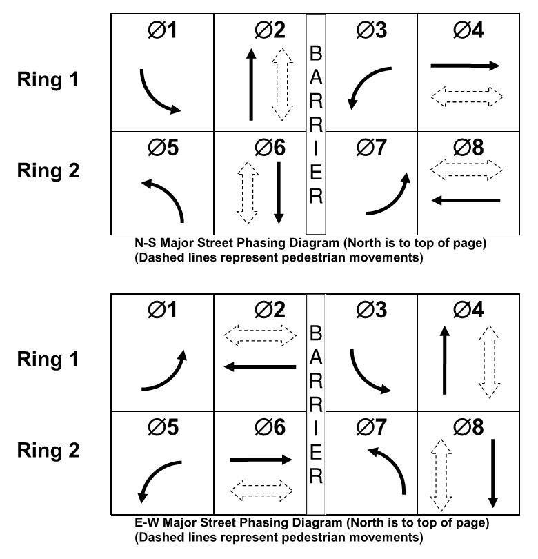
Design Requirements Page | 5-133 9/25/2023 Design Criteria Manual
Figure 5.16-1 - Typical Ring Diagram
5.16.17 General Notes for Signal Plans - Include the following notes, when applicable, on plans for Special Use Permit projects and Capital Improvement Projects:
The Contractor shall notify the St. Louis County Department of Transportation's Division of Operations (Striping Section) at (314) 615-0233, 24 hours in advance of any striping related work. The Contractor shall perform all grinding of existing striping and installation of temporary striping as required by the Engineer. Permanent striping at the intersection will be installed by the St. Louis County Department of Transportation.
Existing underground facilities, structures, and utilities, if shown on these plans, shall be considered approximate only. Verification of the locations of all existing facilities, structures and utilities either shown or not shown on these plans, shall be the responsibility of the Contractor, and shall be verified prior to any grading, excavation, or construction of improvements.
Include the following additional notes, as applicable, on plans for Special Use Permit projects: TRAFFIC SIGNAL PRECONSTRUCTION NOTE:
Unless noted otherwise, all traffic signal work on this project shall be in accordance with St. Louis County Standard Specifications for Road and Bridge Construction, "Division 900, Section 904 – St. Louis County Traffic Signals"; and with "St. Louis County Standard Drawings – Traffic Signal Details". The Contractor shall have said references on the job site at all times during construction/installation of the signalization equipment.
The Section 904 specifications in effect for this project will be those available for viewing on the date the signal plans were approved.
The contractor shall be responsible for checking the Standard Drawings Errata Sheet to ensure their set of drawings is current. The Standard Drawings in effect for this project will be those drawings available for viewing on the date the signal plans were approved.
Include the following note on plans when existing signal conduit and cable is within the project construction limits:
CAUTION! EXISTING UNDERGROUND TRAFFIC SIGNAL CONDUIT/CABLE
It is the responsibility of the contractor/developer to contact St. Louis County Department of Transportation, Division of Operations (Signals Section) at signal_locates@stlouiscountymo.gov or (314) 615-0215 a minimum of 48 hours in advance of construction work for locating and spotting existing traffic signal conduit. In the event the contractor damages the conduit and cable, repairs shall be made within 72 hours at their cost by an electrical contractor, as directed by St. Louis County.
Design Requirements Page | 5-134 9/25/2023 Design Criteria Manual
5.16.18 Intentionally Blank
5.17 Traffic Handling - All detours and lane closures must be handled using traffic control devices conforming to the most current edition of the "Manual on Uniform Traffic Control Devices" (MUTCD) and must be approved by the St. Louis County Department of Transportation ("Department"). The manual, produced by the U.S. Department of Transportation, Federal Highway Administration (FHWA), may be viewed on their Internet website and printed at no charge. The MUTDC Internet website address is mutcd.fhwa.dot.gov
5.18 Supplemental Subdivision Development Requirements - In addition to the requirements and guidelines stated elsewhere in this manual, the following requirements shall also apply to all subdivision development per Chapter 1105.180 of the Revised Ordinances of St. Louis County, also known as "The Subdivision Ordinance of St. Louis County." Where statements in this section conflict with design requirements stated elsewhere in this manual, the more stringent requirement shall govern.
1) Arrangement of subdivision streets shall conform as nearly as possible to St. Louis County's Highway System Plan and the developer shall make provision for the extension and/or relocation of major, collector and minor streets, which impact the property. Except for dead-end streets, streets normally shall connect with streets already established, or provide for future connections to adjoining unsubdivided tracts, or shall be a reasonable projection of streets in the nearest subdivision tracts.
2) Stub streets shall be constructed to the property lines when required to provide for future connections to adjoining undeveloped tracts. Reasonable projections of streets in nearby subdivisions will establish the location of certain stub streets.
3) Where a subdivision abuts or contains an existing or proposed major street, the Department of Planning may require frontage or service streets, double frontage lots with screen planting, and non-access strips at the rear of such lots.
4) Minor street intersection jogs or discontinuities with centerline offsets of less than one hundred (100) feet shall be avoided.
5) Reserved strips of land which control or limit access at the terminus of streets or prevent access to streets located adjacent to undeveloped land are prohibited.
6) A subdivision entrance street shall intersect the major or collector street with an interior angle of seventy (75) to ninety (90) degrees unless otherwise approved by the Department. Each entrance street shall be positioned to provide required sight distance along each intersecting roadway as determined by the Department. Refer to supplemental Drawing 3.2, Sight Distance at Intersections for Sight Distance at Intersections criteria. The edges of the subdivision entrance curb opening shall not project beyond the side property line extended normal to the pavement. Subdivision entrances which do not meet this side property line clearance requirement shall not be approved for construction without a consent letter from the abutting property owner.
Design Requirements Page | 5-135 9/25/2023 Design Criteria Manual
7) A minimum radius of twenty (20) feet at street right-of-way intersection and a minimum radius of thirty-two (32) feet at the back of the curb shall be required. Greater radii and channelization may be required at an intersection with a major or collector street or to provide access for vehicles having large turning radius requirements. The Department may permit a series of comparable cut-off or chords approximating the edge of pavement radius.
8) All interior residential streets intersecting on collector streets shall be directly opposite existing or other proposed streets or shall be a minimum of three hundred (300) feet distant, as measured between street centerlines. All other streets intersecting on arterial, county, or non-residential streets shall be directly opposite existing or other proposed streets or shall be a minimum of four hundred (400) feet distant, as measured between street centerlines.
9) Where a collector street enters or connects with a major street, the Department must approve the entrance plan.
10) Streets shall be constructed to St. Louis County standard specifications.
11) All stub streets in excess of four hundred and fifty (450) feet in length measured from the centerline of the street intersection to the property line or plat boundary, shall be provided with a temporary turnaround. Permits will not be issued for building construction on lots abutting a temporary turnaround as shown on any recorded subdivision plat unless and until the temporary facility is actually constructed and has been approved by the Department. Refer to Standard Drawing C502.05.
Prior to expiration of the land subdivision bond or escrow agreement required of the development under Section 1005.080 of the Subdivision Ordinance, the removal of temporary turnaround surfacing shall be provided for by an Agreement Guaranteeing Road Improvement (Special Escrow), together with a cash sum or Irrevocable Letter of Credit. Refer to Chapter 8 for requirements.
The Department of Planning may grant a variance for temporary turnarounds providing that the following conditions are met:
a) The developer submits to the Department of Planning statements from all prospective lot purchasers affected by the temporary turnaround, excluding the developer himself, declaring that they agree to the use of their driveways for executing the turnaround movements at the terminus of the street and acknowledging that any repairs made necessary due to damage to the driveway caused by the use of their driveway for the turnaround movement shall in no way be deemed the responsibility of St. Louis County; and
b) Provide an easement for the turnaround movement approved by the Department.
12) All streets shall be designed to meet the minimum requirements set forth in the Street Specification Matrix of the Subdivision Ordinance, Section 1005.180, Street Standards, with the exception of large lot subdivisions to which such requirements are not applicable. The matrix, or variable street specification table, is designed to provide
Design Requirements Page | 5-136 9/25/2023 Design Criteria Manual
the maximum allowable flexibility in street construction standards, while at the same time, insuring the protection of the public interest. The widths of right-of-way and pavement are allowed to vary as functions of the type of street and the corresponding intensity of use.
13) Any subdivision platted along an existing street shall provide additional right-of-way, as necessary, along a tangent section of road, to meet the width requirements herein set forth. Additional right-of-way in excess of twenty (20) feet may be required when the subdivision is located on the inside of a curved roadway or conditions exist on the opposite side of the right-of-way which dictate right-of-way offset from the right-of-way centerline. When the subdivision is located on only one side of an existing street or County road, one-half of the required right-of-way width shall be provided, measured from the centerline of the right-of-way as originally established, unless otherwise directed by the Department. The centerline must meet the requirements of the Department with regard to radius when located on a curved roadway. Right-of-way dedication requirements along State and County roads will not be credited towards the developer's traffic generation assessment or trust fund contribution except for right-ofway in excess of that allowed by Section 1005.180 of the Subdivision Ordinance. The Department may request right-of-way dedication in excess of twenty (20) feet if concurred in by the Department of Planning. The developer may appeal such request to the County Council. If the Planning Department does not concur in the requested right-of-way dedication, the Department may appeal to the County Council.
14) Roadway easements for the servicing of large lot subdivisions shall have a minimum width of fifty (50) feet.
15) A subdivision plat involving new or existing streets crossing railroad tracks shall provide adequate rights-of-way, including approach rights-of-way and slope easements for construction of an underpass or overpass, unless otherwise specified by the Commission. Approval of the State of Missouri Public Service Commission and the Department must be received relative to all railroad crossings. The developer may be required to install crossing signals.
16) A street on which residential lots front and which parallels, but is not adjacent to a railroad right-of-way, shall be at a distance from the railroad right-of-way sufficient to provide lots with a minimum depth of one hundred sixty (160) feet.
17) Commercial and industrial subdivision streets shall be constructed with vertical curbs on both sides except for locations in the Earth City and Chesterfield Valley Areas which require open drainage facilities for stormwater.
18) Where in the best interest of the traveling public, to provide circulation, health and safety measures, the Department may require a street to be dedicated to public use.
19) The pavement width set forth in the street specifications matrix (Section 1005.180 of the Subdivision Ordinance) for multiple family access streets does not allow for, nor will parking be permitted on the streets. For each parallel parking space adjacent to these streets, an additional width of 10 feet shall be provided. Additional parking
Design Requirements Page | 5-137 9/25/2023 Design Criteria Manual
requirements shall be provided herein and/or to the standards established by the Commission.
20) If roadways are designated to be private roadways, these roadways shall remain private forever. Maintenance of private roadway will be the responsibility of the property owner(s) or trustees forever. Private roadways are required to be built to public street standards.
21) Additional lanes and/or widening, pavement thickness, drainage facilities, granular base and/or traffic control devices may be required to accommodate heavy traffic volumes, unsuitable soil conditions, steep grades, or other conditions not apparent at the time of the Preliminary Plan approval.
22) The developer shall provide adequate temporary off-street parking for construction employees. Parking on non-surfaced areas shall be prohibited in order to eliminate the condition whereby mud from construction and employees vehicles is tracked onto the pavement causing hazardous road and driving conditions.
23) If any public roads are proposed within a development, they must be built above the 100-year flood elevation with proper freeboard or protected from flood damage by an approved levee. Any roads and/or drives proposed below this elevation, not protected by an approved levee, are to be private and remain private forever.
24) Temporary or permanent turnarounds may be requested to accommodate school buses. The turnarounds shall have a pavement radius of fifty-five (55) feet. Refer to Standard Drawing C502.10. If school bus turnarounds are required, the school district will submit verification that they will permit buses to enter the subdivision utilizing the turnarounds.
25) Street creep typically occurs opposite "T" intersections, at the ends of cul-de-sacs and on the outside of curves. In order to reduce the adverse effects of street creep, the installation of Type A2 expansion joints (See Standard Drawing C502.13) are required on residential streets at the following locations:
a) At end of radius on each approach to a "T" intersection;
b) Across the throat of cul-de-sacs;
c) The beginning (PC) and the end (PT) of curved sections of street.
For construction details of pavement sections at cul-de-sacs and "T" intersections, refer to Standard Drawings C502.01, C502.02, and C502.06
26) Prior to any action by the Department on a private roadway or public road right-of-way presently not maintained by St. Louis County, the residents, trustees, and/or property owners along the private or non-County maintained roadway shall be required to sign an affidavit stating the type of materials which have been used to maintain the roadway, the hauler of those materials, and the supplier or source of those materials. Also, in areas that may contain contaminated substances as identified by the U.S.
Design Requirements Page | 5-138 9/25/2023 Design Criteria Manual
Environmental Protection Agency (EPA), provide verification of review by the Department of Community Health and Medical Care.
27) In subdivision developments it is recommended that two (2) access points be established whenever possible for the benefit of emergency vehicles.
28) In the unincorporated areas of St. Louis County, streetlights are required to be installed in new subdivision developments as a condition of the development approval The cost of maintaining the streetlights shall be borne by the subdivision residents as a trustee function St. Louis County shall not be responsible for any of the cost of or maintenance of subdivision street lighting. Street lighting in unincorporated St. Louis County subdivision developments, including illumination standards, is addressed in Section 1005.320.1 of the St. Louis County Subdivision Ordinance
29) When portions of roadway improvements required for the safety of the public require the acquisition of additional right-of-way and easements from private property, the normal sequence of design, right-of-way acquisition and construction shall commence immediately upon approval of the requested rezoning. If the developer is unable to acquire the necessary right-of-way and easements through negotiation with the particular property owners involved, St. Louis County will acquire same through eminent domain proceedings. The cost of appraisals, negotiations, administration, court proceedings and all associated costs incurred by County proceedings shall be paid by the developer.
30) Installation of Landscaping and Ornamental Entrance Monument construction shall be reviewed by the Department for sight distance considerations and approved prior to installation or construction.
31) Proposed development-utilizing roadways with structurally deficient pavement within the site, or providing access to the development from such roadways, may be required to overlay the existing road surfacing or make other remedial improvements, as required by the Department, to bring the structural stability of the pavement up to minimum requirements.
32) All longitudinal joints in concrete pavement shall be constructed along proposed lane lines as directed by the Department. Where proposed lane striping and existing longitudinal joints do not coincide, a two (2) inch overlay of Type "C" Bituminous Concrete Wearing Surface shall be required.
5.19 Landscaping, Ornamental Entrance Monuments and Signs - All landscaping where permitted within St. Louis County road right-of-way shall be planted and installed in accordance with St. Louis County Standard Specifications. The recommended location for street trees varies between five (5) and ten (10) feet from the road right-of-way line on private property, depending upon the type of tree being planted. Permits shall be required for the planting of hedges, shrubs, landscaping, ornamental entrances and monuments, berm slopes, trees, etc. within the right-ofway and shall not be issued without the approval of the subdivision trustees.
Design Requirements Page | 5-139 9/25/2023 Design Criteria Manual
1) Location - Trees shall not be located within a street right-of-way unless the Planning Commission, or the Director of Planning and the Director of Transportation, has granted a variance. Location of new street trees shall not be allowed within the following areas: three (3) feet of any curbs, twenty-five (25) feet of street lights, or ten (15) feet of street inlets or manholes. Clear Zone requirements must also be met.
No plant material with a mature height exceeding twenty-four (24) inches in height above the elevation of the adjacent street pavement shall be planted within the corner triangle area bounded by the property lines of a corner lot and a line connecting two (2) points on the property lines each measured thirty (30) feet from the intersection of the two (2) property lines at the street intersection (Figure 5.9-3). Likewise, no trees may be planted within the triangular area that have bottom branches lower than seven (7) feet above the elevation of the adjacent street pavement.
No plant material with a mature height exceeding twenty-four (24) inches in height above the elevation of the adjacent street pavement should be planted within the sight distance triangle as defined by supplemental drawing 5.2 Sight Distance at Intersections. Likewise, no trees should be planted within said area that have bottom branches lower than seven (7) feet above the elevation of the adjacent street pavement.
Bushes or shrubs shall not be permitted within the public right-of-way where they shield or screen fire hydrants.
2) Ornamental Entrance Monuments and Signs - Structures and/or signs proposed at subdivision and commercial development entrances shall conform to the requirements of the Zoning Ordinance.
The width, height, grade and location of all entrance monuments and signs shall be reviewed with relation to the existing and proposed streets and/or major commercial driveway intersections for possible sight distance restrictions affecting nearby vehicular and pedestrian traffic and other requirements as follows:
a) Ornamental entrance monuments and signs when located in medians approaching street intersections shall be located a minimum of twenty (20) feet from the prolongation of the intersecting road right-of-way or easement line and constructed symmetrically about the median centerline.
b) Monuments and signs located in proximity to the street intersection corners, shall not be located within the road right-of-way
c) Monuments and signs located within the Corner Triangle area of the street intersection corners or within the sight distance triangle as defined by supplemental Drawing 5 2 Sight Distance at Intersections shall be subject to the height limitations governing trees and plant materials
d) Ornamental entrance monuments and signs shall not be placed or constructed within the public road right-of-way or easement without authorization by the Department through the issuance of a permit.
Design Requirements Page | 5-140 9/25/2023 Design Criteria Manual
e) Plans shall be provided showing elevation and section views of the proposed construction. Plans shall indicate the location of the adjacent right-of-way, easements, curbing, sidewalk, street pavement, utilities and/or landscaping.
f) Plans for monuments and sign structures shall be approved by the Department of Public Works prior to issuance of the Department of Transportation's permit. (Where special permits, i.e., building, electrical and/or plumbing are required, they shall accompany the plans.)
g) Corner triangle area and sight distance triangles as defined by supplemental Drawing 5.2 Sight Distance at Intersections shall be shown on the plans.
h) Permit for construction will be issued initially to the developer or later to Trustees or other individuals designated in the trust indentures.
i) Where the entrance monument and sign have not been specifically provided for in the recorded indentures, amendments shall be recorded prior to plan approval and permit issuance.
j) Indentures must provide for maintenance and repair of structure and sign authorized by permit.
k) Indentures must hold County harmless from all claims, demands and suits of any kind arising out of or in conjunction with any permits issued.
3) Permits - When it is determined that certain barriers (other than trees and shrubbery) do not constitute a hazard or nuisance, the property owner may be notified to obtain a Special Use Permit from the Department. If the property owner fails to submit a request for a permit within thirty (30) days, the barriers shall be removed from the rightof-way.
4) Hazardous Situations - The following guidelines have been established to properly identify possible plant material and barrier hazards:
a) Fences that obscure the sight distance for motorists entering an intersection could be a hazard. Also, fences that are located directly behind the edge of pavement could be a hazard to pedestrians depending upon the width of pavement and the volume of traffic.
b) Rocks, railroad ties, or other posts located within the County right-of-way may not necessarily be a hazard. These barriers could be hazards if they are located in the path of normal pedestrian traffic and/or are located so close to the edge of pavement that motorists could strike them.
c) Plant material located on the corners of intersections could be a hazard if motorists are unable to see cross traffic approaching.
Design Requirements Page | 5-141 9/25/2023 Design Criteria Manual
d) Trees with low branches across a sidewalk or walkway could be a hazard to pedestrians. All limbs must be trimmed to a minimum height of 80” above the pedestrian access route.
5) Inspection and Removal - Within the St. Louis County right-of-way adjacent to the public roadway, certain cases may dictate the need to remove any barriers, plant material, and trees within the public road right-of-way. The discretion and authority to remove such barriers, plant material, and trees in the public road right-of-way is the function of the St. Louis County Department of Transportation.
In order to ensure that plant material, tree and barrier hazards have been removed from County streets and parkways where necessary, the following policy shall be effective:
a) The Department shall investigate all possible hazards created by plant material, trees and barriers that are known through citizen complaints and/or by report from Departmental personnel.
b) When it is determined that certain plant material, trees and/or barriers installed by the abutting property owner are hazardous (that is, obstruct or endanger either pedestrian or vehicular traffic) or constitute a nuisance, the Department shall notify the property owner of the hazard or nuisance and request removal of same as soon as possible.
c) After a reasonable length of time, the Department will conduct a follow-up investigation to determine if the property owner has corrected or removed the hazard or nuisance.
d) If the notified property owner has not corrected the hazard or nuisance, the Department will make arrangements to remove said hazard or nuisance as soon as possible without further notification to the property owner.
6) Other Landscaping Concerns
a) Ground Cover - The Department may require sodding or other means of ground cover to insure erosion control.
b) Common Ground or Common Land - The Department may require the clearing of underbrush, sodding, seeding, and other landscaping improvements in that portion of the common ground or common land that has been altered or graded.
For additional requirements, refer to Section 1005.340 of the Zoning Ordinance.
5.20 Street Name Signing - Reflectorized street signs bearing the name of the street, as designated on the record plat, shall be placed at all street intersections. Each and every intersection formed by the developer shall have at least one street name sign for each intersecting street mounted in a bracket on top of one post. Two sets of street name signs on separate posts shall be required at intersections where one street is thirty-eight (38) feet wide or greater, or when one street is an arterial roadway. Refer to Standard Drawings C903.10.
Design Requirements Page | 5-142 9/25/2023 Design Criteria Manual
The Department shall approve the location and inspect the installation of street name signs in all subdivisions. The size, height, and type of sign shall be in accordance with the specifications of the Department. Street signs shall not be required for large lot subdivisions other than at each intersection of a designated private roadway easement with an existing or proposed publicly maintained street.
The required sign post location shall depend upon the traffic volume on the roadway and the width of pavement. Each post shall be placed a minimum of 3.5 feet from the back of the curb. Street name sign posts shall be located where they may be used for future "Stop" or "Yield" signs. This means that one set of street name signs shall be installed on the near right corner for the lesser volume roadway. Also, when one of the intersection streets is 32 feet or greater in width, or when one street is an arterial roadway, two sets of street name signs shall be required. Refer to Standard Drawings C903.10.
5.21 Guardrail - Guardrail shall be required to protect traffic from hazardous features. Guardrail warrants will be evaluated per the AASHTO Roadside Design Guide.
Terminal crashworthy end sections will be required for both directions of traffic flow on two-way pavement. Where the distance between terminal sections of two sections of guardrail will be 100 feet or less, one continuous length of guardrail shall be installed.
Guardrail shall be provided for protection of traffic adjacent to creeks and lakes, at bridge ends, piers, signs and headwalls, and other obstacles as directed by the Department. Refer to Standard Drawings C606.01 through C606.23.
Design Requirements Page | 5-143 9/25/2023 Design Criteria Manual
Chapter 6 Reports and Studies
6.0 Introduction - This chapter contains the requirements for the various reports and studies which may be required by the Department in the plan development process.
6.1 Geotechnical Reports - A Geotechnical Report shall be required where grading and proposed improvements on the site are located in an area where soil conditions are susceptible to rapid erosion, landslide, settlement and/or creep. The report shall verify the adaptability of grading and improvements with soil and geologic conditions. A statement of compliance with this study, signed by the Professional Engineer preparing the report, shall be included on all Site Development Plans. The development plan and improvement plans shall be designed to conform to the requirements and conditions of the Geotechnical Report. A Professional Engineer shall be required to inspect construction in accordance with the grading and soils requirements and conditions contained in the report.
6.1.1 When Required - The Engineering Geologic Map of St Louis County, Missouri (1971), Edwin E. Lutzen and John D. Rockway Jr., contained in the Missouri Geological Survey and Water Resources Engineering Geology Series No. 4 and available through the Missouri Department of Natural Resources shall be used to ascertain whether a Geotechnical Report shall be required. At this time, a report is required for sites located in Units IIa, IIIa, IVa, VI, and Xa, and Units IIb, IIc, and IId when specific site conditions or development type necessitate a report.
In all areas of questionable soil stability such as sinkholes, ponds, marshy areas, etc., the Department shall be notified prior to commencement of grading so that these locations can be inspected.
6.1.2 Study Requirements
1) For reports concerning proposed developments in Units IIa, IIIa, IVa, or Xa, the consultant should prepare conditions within the report covering the following, at a minimum.
a) Erosion of Silt-Rich Loessial Soil - What should be done to minimize surface erosion during and after construction? Also, what measures should be taken to address erosive velocities at discharge points?
b) Developments on Slopes Greater than 20% - Soil creep is a potential problem on slopes this steep, and developments in these areas will require engineering analysis and solutions.
c) Cut and Fill - Construction of cut and fill slopes in these areas should be detailed to assure slope stability.
Reports and Studies Page | 6-1 9/25/2023 Design Criteria Manual
2) For reports done on proposed developments in Unit VI, the consultant should prepare a report covering the following, at a minimum.
a) Natural Slope Stability - Are the natural slopes on shale stable enough for the density of development proposed?
b) Swelling Soils - The potential for swelling soils in Unit VI and their effect on home and road foundations should be discussed.
3) Additional considerations that can be covered in these reports include effect of stream erosion on private property, foundation design, foundation drainage, road design, excavations, etc.
4) The reports for the erosion-prone area do not necessarily require subsurface investigation. The shale areas, however, would almost certainly require shallow exploration. The reports shall be prepared under the supervision of and sealed by an engineer.
5) Developments that require more detailed soils information are those with very dense housing (greater than 3 to 4 houses per acre), extensive grading and site preparation (including cut and fill), steep slopes, etc. Some developments can be less critically reviewed due to minimal site disturbance and low-density housing (2 or less houses per acre).
6) There are other areas besides Units IIa, and VI within the County where dense developments will require sound engineering. An example is the West County area where steep slopes and narrow valleys are encountered. Although landslides in these areas are not likely, erosion and flooding problems will become more severe as this area is developed.
6.1.3 Sink Hole Requirements - Construction of new roadway pavement will not be permitted over sinkholes. Excavation and/or treatment of sinkholes shall be authorized by the Department of Transportation through the issuance of a grading permit prior to commencement of the excavation. Any areas identified as sinkholes will require a sinkhole report. This report will require that the sinkhole(s) shall be inspected to determine if it is functioning with regard to drainage and the sinkhole shall be treated as follows:
1) All sinkhole crevices shall be located on the plan. If the sinkhole is either in the public road right-of-way or within 10' of the public road right-of-way, it shall be excavated to the crevice, treated and brought to grade by the construction of a manhole or inlet with outfall pipe, etc.
2) Functioning sinkholes shall be utilized as a point of drainage discharge by a standard drainage structure with a properly sized outfall pipe provided to an adequate natural discharge point, such as a ditch, creek, river, etc.
3) Non-functioning sinkholes and sinkholes under a proposed building may be capped.
4) Sinkholes may be left in their natural state; however, they will still require properly
Reports and Studies Page | 6-2 9/25/2023 Design Criteria Manual
sized outfall pipe or swale to an adequate natural discharge point.
5) All sinkholes affecting County right-of-way (typically within ten (10) feet) must be inspected by the Department prior to treatment. Sinkholes not affecting County rightof-way must be inspected by the Department of Public Works. Special siltation measures shall be installed during the excavation of sinkholes and during the grading operations to prevent siltation of the sinkhole crevice.
In general, the following procedure shall be followed in treating sinkholes:
a) Excavation - Prior to filling operations in the vicinity of a sinkhole, the earth in the bottom of the depression will be excavated to expose the fissure(s) in the bedrock. The length of fissure exposed will vary but must include all unfilled voids or fissure widths greater than 2-inch maximum dimensions which are not filled with plastic clay.
b) Closing Fissures - The fissure or void will be exposed until bedrock in its natural attitude is encountered. The rock will be cleaned of loose material and the fissures will be hand-packed with quarry-run rock of sufficient size to prevent entry of this rock into the fissures, and all the voids between this rock filled with smaller rock so as to prevent the overlying material's entry into the fissures. For a large opening, a structural (concrete) dome will be constructed with vents to permit the flow of groundwater.
c) Granular Filter - Material of various gradations as approved will be placed on top of the hand-packed rock with careful attention paid to the minimum thicknesses. The filter must permit either upward or downward flow without loss of the overlying material.
The fill placed over the granular filter may consist of a granular material or an earth fill compacted to a minimum density of 90% as determined by ASTM D1557-64T.
d) Supervision - Periodic supervision of the cleaning of the rock fissures must be furnished by the Soils Engineer. Closing of the rock fissures will not begin until the cleaning has been inspected and approved by the Soils Engineer.
During the placement and compaction of earth fill over the filter, supervision by the Soils Engineer shall be continuous. Earth fill densities will be determined during the placement and compaction of the fill in sufficient number to ensure compliance with the specification. The Soils Engineer is responsible for the quality of the work and to verify that the specifications are met.
6.1.4 Supplemental Design Requirements
1) Maximum Slope Restrictions - In general, all slopes shall be graded to meet St. Louis County's standard 3:1 or flatter slope for both cut and fill. 2:1 slopes may be approved by the Department where their use is supported by detailed soils information. If the preliminary grading plans or site plans propose high terraces, the soils report should indicate measures to intercept and divert surface water from flowing over terraces and walls.
Reports and Studies Page | 6-3 9/25/2023 Design Criteria Manual
6.1.5 Statement of Compliance with the Geotechnical Report - As indicated previously in this section, a statement of compliance with the Geotechnical Report shall be required prior to St. Louis County's approval of the Site Development Plan, Final Development Plan and/or Improvement Plans required for the development. The statement of compliance shall include, but not be limited to, the following:
(Insert Company Name) and the undersigned engineer have not prepared the plan on this sheet. The seal of the undersigned professional engineer has been affixed at the request of Saint Louis County and is a professional opinion to indicate that the undersigned has reviewed the plans and that in his opinion the grading and improvements relative to slope construction as shown on the plans, as well as the foundations, are compatible with the soil and geologic conditions at the site as described in the geological report for the development dated (Insert Report Date).
(Insert Company Name) and the undersigned assume no responsibility for services by others (pursuant to RSMO 327.411).
Construction means and methods for implementation of the grading plan shall be left to the developer/contractor. Observations of the developer/contractor's compliance with the applicable specifications shall be identified and verified in writing.
(Insert Company Name Here) Seal
(Engineer’s Signature Here)
(Insert Engineer's Name and Registration Number)
Reports and Studies Page | 6-4 9/25/2023 Design Criteria Manual
6.2 Flood Plain Study - Any development within regulatory floodway shall be prohibited unless it has been demonstrated through hydrologic and hydraulic analyses performed in accordance with standard engineering practice by a Missouri Registered Professional Engineer that the floodway encroachment will not result in any increase in flood levels during the occurrence of the base (100-year) flood discharge.
6.2.1 When Required - A floodplain study shall be provided for development within floodplain on all tracts or parcels of land within unincorporated St. Louis County identified as numbered and unnumbered A Zones, and AE, AO, and AH Zones on the current Flood Insurance Rate Maps (FIRM) for St. Louis County. No development within these areas shall be permitted except after the issuance of a floodplain development permit.
6.2.2 Study Requirements
1) The floodplain study plan shall comply with all requirements of Chapter 1003 (the Zoning Ordinance), and Chapter 1008 (Floodplain Management Regulations) of the Revised Ordinances of St. Louis County Missouri.
a. For any minor projects that do not cause obstruction to flow in floodplain and do not reduce the conveyance capacity of the floodplain (i.e., trenching or boring of utility facilities), the floodplain study plan shall include a floodplain study plan delineating the floodplain and regulatory floodway limits per the current Flood Insurance Rate Map (FIRM) and all proposed improvements, signed and sealed by a Missouri Registered Professional Engineer. Minor projects shall be determined by St. Louis County.
2) An Application for Floodplain Development shall be submitted for all work located within the floodplain
3) If unauthorized fill has been placed on a tract, the floodplain study shall be based upon the existing terrain prior to the placement of the unauthorized fill.
4) All plan sheets of the floodplain study plan shall be signed and sealed by a Missouri Registered Professional Engineer.
5) The floodplain study plan shall be submitted, reviewed, and approved prior to issuance of any building permits or approval of any Preliminary Plans, Site Plans, or Site Development Plans.
6) The base flood elevation and floodplain and floodway limits based on the current FIRM shall be delineated on the plans. The FIRM panel number and the delineated location of the development on the FIRM shall be provided on the plans. Delineation of the surveyed 100-year high water elevation limits shall be provided if different from the FIRM floodplain limits.
FEMA Flood Insurance Rate Maps (FIRM) are available online through the FEMA Map Service Center (www.fema.gov). The direct Flood Map Service Center address is: https://msc.fema.gov/portal. Enter St. Louis County, Missouri in the Search Box and click on the "Search" button.
Reports and Studies Page | 6-5 9/25/2023 Design Criteria Manual
7) All necessary permits and approvals from other agencies, including the Metropolitan St. Louis Sewer District (MSD) and the U.S. Army Corps of Engineers, shall be obtained prior to floodplain study approval.
8) An Engineering No-Rise certification signed and sealed by a Missouri Registered Professional Engineer shall be provided prior to floodplain study approval for any work within a regulatory floodway.
a. For minor work as defined above, which is located in the regulatory floodway, the No-Rise Certification may be certified with a narrative statement in lieu of a hydraulic study.
Reports and Studies Page | 6-6 9/25/2023 Design Criteria Manual
6.2.3 Supplemental Design Requirements
1) New construction and substantial-improvement structures shall have the low floor elevated to 1 foot above the base flood elevation.
2) New public roadways shall be constructed so that roadway shoulders are set to a minimum of 1 foot above the base flood elevation.
6.2.4 Supplemental Plan Preparation Requirements
1) All existing and proposed structures shall be shown on the plans along with their low floor elevations.
2) All existing and proposed improvements shall be identified on the plans.
3) A nearby benchmark referenced to the North American Vertical Datum of 1988 (NAVD88) shall be utilized on the plans. One source of such benchmarks is the St. Louis County Benchmark System.
4) A statement signed and sealed by a Missouri Registered Professional Engineer, or a Missouri Registered Professional Land Surveyor shall be submitted for review for any on-site benchmark(s) established through Global Navigation Satellite Systems (GNSS). This statement shall indicate the method utilized to establish the onsite benchmark(s), the published NAVD88 elevation of a nearby benchmark, and the GNSS observed elevation of said nearby benchmark.
6.3 Traffic Impact Study - In order to best preserve the functionality of the County roadway network, it is important toevaluate its operational effectiveness. New developments change traffic volumes and patterns along the system. This section provides guidance for determining reasonable assessments of the impacts developments are likely to have on the existing transportation system via traffic impact study (TIS) The specific content of a TIS will vary depending on the site and prevailing conditions.
The performance standards of traffic impact studies as contained within this chapter are intended to be a general guideline. However, the specific details, methodologies, and study requirements shall be confirmed and agreed upon by the Department and the Applicant, or an appropriate representative, such as a traffic engineering consultant, prior to formal submission of the study.
Reports and Studies Page | 6-7 9/25/2023 Design Criteria Manual
6.3.1 When Required - A traffic impact study (TIS) may be required under any of the following conditions:
1) When the proposed development is projected to generate 100 or more trips per hour during the peak generating time for the development.
2) Residential subdivisions with more than 60 units
3) When the proposed new approach is to an intersection already operating at LOS "D" or worse.
4) When the developer is requesting a new traffic signal.
5) When modifications of an existing traffic signal are being requested (timing/phasing changes, hardware modifications, etc.).
6) When using an existing TIS in which the data is more than two years old.
7) When proposed access is inconsistent with St. Louis County Access Management Guidelines.
When none of the five conditions above are met, the Department may request a brief memorandum summarizing the extent of the proposed development and why a TIS is not required. A TIS may not be required in situations where the project’s impact on traffic is obvious and where the Department is agreeable to the proposed mitigation measures without conducting a TIS. However, if the County recommends mitigation measures, and the developer does not agree with those measures, the developer has the option to do a TIS to prove or disprove the validity of the recommended mitigation measures. As an alternative, it may be requested that an appropriate level of documentation be completed to illustrate the adequacy of the mitigation measures.
In addition, analysis of individual traffic impact study components addressing specific concerns may be required dependent upon site specific conditions, regardless of the conditions above. These may include site distance study, traffic control warrants, auxiliary turn lane warrants, etc.. Individual traffic impact component analysis may also be required for design exceptions requested during the plan review process or to justify relief from required improvements.
To determine if a TIS is required, the developer or consultant should contact the Department’s Planning Division.
6.3.2 Scoping - For developments considered to be relatively straightforward, a Consultant may submit a Scoping Worksheet in lieu of a scoping meeting. For developments with more potential issues or controversies, a scoping meeting will be required.
6.3.2.1 Scoping Worksheet - For relatively simple, noncontroversial developments, a Consultant may submit a Scoping Worksheet as shown on Form 6.3.2.2 along with a conceptual site plan including proposed access points. The worksheet asks for information about the project, study scenarios, and data sources. The Department will review the information provided on the worksheet and either approve the scope, send comments, or request a scoping meeting.
Reports and Studies Page | 6-8 9/25/2023 Design Criteria Manual
Form 6.3.2.2 - Traffic Study Scoping Worksheet
Project Information
Name: Location:
Description:
Anticipated Opening Year:
Anticipated Build-Out Year:
Owner Information
Contact Name:
Organization:
Phone Number: E-Mail Address: Traffic Consultant Information
Contact Name:
Organization:
Phone Number: E-Mail Address:
Participating Agencies (MoDOT, Municipalities, etc.)
Study Area Boundaries (Roadways/Intersections to be included)
Planning Scenarios (Peak Hours, Planning Horizons)
Data Sources
Assumed Growth Rate
Anticipated Trip Reductions (Pass-By, Internal Capture, Alternative Mode, etc.)
Analysis/Simulation Tools
Miscellaneous Comments/Issues
County Approval
Reports and Studies Page | 6-9 9/25/2023 Design Criteria Manual
6.3.2.2 Scoping Meeting - Relevant agency representatives (from state, municipalities, etc.) should attend the scoping meeting as part of the overall coordination of the development and TIS. It is in the best interest of the development team to attend the scoping meeting and submit the TIS prior to the development plan layout being finalized, if possible.
Scope topics will include identification of intersections that are to be studied (or excluded) in the TIS, locations and type of development planned, study horizon expectations, development or site-specific characteristics (e.g., directional distributions) and methodology (e.g., trip generation calculation methods, analytical tools or methods, etc.) to be used in the TIS. A sample Scoping Meeting Agenda is shown in Exhibit 6.3-1. The applicant shall bring a plan showing:
• The location of the site
• Existing and proposed land use(s) and square footage and/or number of units for the subject site.
• Proposed access and its relationship to adjacent properties and their existing/proposed access
• Preliminary estimates of the development’s trip generation at build out (or critical phases if a large, phased development). This should include both average daily traffic and peak hour traffic.
• The peak hours of analysis (AM, PM, weekend, other)
This information will assist in determining the level of detail and extent to which the TIS will need to address the items within the Scope of Work. Minutes of the scoping meeting shall be recorded by the Consultant and may be submitted as part of the technical memorandum, as described in Section 6.3.3.
Exhibit 6.3-1 - Scoping Meeting Agenda
Reports and Studies Page | 6-10 9/25/2023 Design Criteria Manual
1.0) Introductions 2.0) Development Proposal 2.1) Location 2.2) Land Use (Existing and Proposed) 2.3) Conceptual Site Plan with Proposed Access 2.4) Phasing, if applicable 3.0) Study Area 3.1) Surrounding Land Uses 3.2) Adjacent Streets 3.3) Nearby Intersections 4.0) Data Sources 4.1) Traffic Counts 4.2) Trip Generation 4.3) Trip Distribution 5.0) Study Scenarios 5.1) Peak Hours 5.2) Design Years 6.0) Known Developments in Study Area 7.0) Known Issues in Existing Transportation Network 8.0) Complete Streets Requirements 9.0) Other Miscellaneous Issues/Discussion Points
6.3.3 Technical Memorandum - Prior to submitting the study with analysis, to the Consultant will submit a technical memorandum describing assumptions to be used in the study. These assumptions may include, but are not limited to, a list of intersections to be included in the study, trip generation, trip distribution, and/or growth rates. Agency agreement on study assumptions could decrease review time of the final study. Scoping meeting minutes may be included in the technical memorandum if such a meeting took place, and the minutes were not previously submitted.
6.3.4 Study Requirements - This section lists elements typical to a TIS. Some contents may vary depending on the nature of the development in question, subject to agreement amongst the Developer's Traffic Consultant and any reviewing agencies, such as Missouri Department of Transportation and Municipal entities.
6.3.4.1 Site Description - The TIS shall have a description of the proposed development and limits of the study area. The study should identify:
1) The location, within the site, of each land use.
2) All site access points.
3) All existing access points where traffic movements could be affected by new access.
4) All intersections, either signalized or unsignalized, that are impacted by the project.
6.3.4.2 Study Scenarios - Required study scenarios may vary depending on the nature of the proposed development and surrounding developments as well as roadway conditions. Scenarios selected for study must provide reasonable comparisons between developed (Build) and undeveloped (No-Build) conditions. Typically required scenarios include:
1) Existing - A scenario demonstrating the current conditions of the study area utilizing most recent signal timing information and traffic volume data no more than two years old.
2) Build - A scenario demonstrating reasonably expected conditions at the completion of the proposed development or a proposed phase of development.
3) Design Year - A scenario demonstrating reasonably expected conditions at some point in the future as agreed upon by the Developer’s Traffic Consultant and any reviewing agencies.
4) No-Build - A scenario demonstrating reasonably expected conditions should the proposed development not occur. This scenario is to be included for comparison with Design Year scenarios and Build scenarios in which the Build Year is more than two years after the Existing Year.
Each scenario (discussed above) will be analyzed during peak hours – typically the weekday morning peak and weekday evening peak (from 6:00 to 9:00 a.m. and 3:00 to 6:00 p.m.). Depending on the nature of the proposed development and/or the surrounding land uses, additional analysis time periods may be required.
Reports and Studies Page | 6-11 9/25/2023 Design Criteria Manual
6.3.4.3 Trip Generation and Distribution - The TIS shall include information on the existing and site generated traffic volumes within the study area for all agreed upon peak periods. Peak hour volumes must be shown for the adjacent existing and proposed intersections and access points by turning movement direction.
Sources for projected traffic volumes shall be indicated. Trip generation data is sometimes available directly from the developer based on other similar built-out developments and may be used with Department approval. Trip generation may also be calculated from the data contained within the latest edition of the ITE Trip Generation Manual or other industry publications. Data limitations (sample sizes, R-squared values, etc.), data age, choice of average rate versus statistical significant modification shall be presented and discussed. In the event data is not available, the applicant must conduct a local trip generation study and provide sufficient justification for the proposed generation rate. Methodologies for trip reductions associated with pass-by trips, common trips, and alternative transportation modes shall be discussed and agreed upon.
Trip distribution may be based on traffic forecasts from East-West Gateway COG, market analysis, existing traffic flows, applied census data, and professional judgment. A discussion on site-specific access issues and access management issues within the study area is required that may include the following, among others, if applicable:
• Cross-access
• Inter-parcel access
• Turn restrictions
• Truck access
• New intersections (signalized and unsignalized)
Since on-site circulation affects off-site traffic conditions, it will be important to evaluate the on-site circulation system near the access points. The TIS must demonstrate that there will be enough stacking distance on-site to accommodate ingress of traffic so as not to impact the off-site roadways. An on-site circulation evaluation may not be applicable for all proposed projects.
6.3.4.4 Analysis - The study shall include, for the existing as well as future total traffic flow, level of service evaluation, queue lengths, and intersection or access traffic control device requirements. Peak hour intersection levels of service shall be determined for signalized and un-signalized intersections within the study area based on procedures described in the latest edition of the Highway Capacity Manual (or equivalent approved by County). Synchro is an acceptable analytical tool. Simulation using the appropriate tools (PTV Vissim®, SimTraffic®, or others) may be required in some applications. The use of simulation will be discussed during the scoping meeting and may not be necessary in all studies. County reserves the right to request simulation after the scoping meeting if it is determined necessary in order to adequately evaluate the impacts of the proposed development.
Reports and Studies Page | 6-12 9/25/2023 Design Criteria Manual
Geometrics for intersections and new access should be analyzed, as well as the storage requirements, adequacy or need for additional through traffic lanes or auxiliary turn lanes for existing, future on-site and future total traffic conditions. Analysis of potential conflicts of proposed access locations with existing and/or proposed adjacent access or intersection traffic lane configurations for the future total traffic conditions should be conducted. Analysis of the accident data may be useful in this regard.
Other factors that should be considered include weaving pattern, layout and number of parking spaces and on-site circulation.
Worksheets or electronic files of the analysis prepared for existing and future traffic flow, using Synchro, HCM or any other tool shall also be provided.
6.3.4.5 Special Analysis/Issues - This section provides County with opportunities to request specific focused traffic analyses relevant to the proposed development. These could include access management, travel demand management plan, cut-through traffic and residential quality of life, truck estimates, safe routes to school, emergency routes, bus route, BRT, bus turnouts etc. Any special analyses and/or issues will be discussed during the scoping meeting.
6.3.4.6 Impacts and Mitigation - All recommended on-site, and off-site improvements required to mitigate projected traffic congestion or safety issues should be identified with the resultant traffic flow conditions indicated for comparison to the existing conditions. The key elements of the project impact analysis include:
• A peak hour level of service for all movements in each study period– identify whether the traffic from the proposed project will result in a significant impact (see below)
• The appropriateness of access locations, access management strategies, and the need for future traffic signals per SLCDOT's Access Management Guidelines (Section 4.3)
• Turn lane requirements per SLCDOT's Access Management Guidelines (Section 4.6)
• Sight distance where new access points are recommended
• Appropriateness of acceleration or deceleration lanes
• Signal warrant analyses if new traffic signals are recommended
• Impacts on any special issues that were identified such as safety or community concerns
Project impact is measured by comparing “No Build” conditions with "Build" conditions. The specific measures of effectiveness used in the comparison will vary based on the analysis. For example, if an isolated intersection is being analyzed, then the v/c ratio, LOS, and delay shall be measured. However, if a corridor is being analyzed, then travel time shall be measured. The following conditions shall be used to determine if impacts are significant and warrant further examination:
Reports and Studies Page | 6-13 9/25/2023 Design Criteria Manual
1) Intersection v/c (volume/capacity) ratio – any of the following conditions are considered "significant":
a) If No Build overall v/c <50%, then an increase in the v/c of 10% or greater;
b) If No Build overall v/c >=50% and <80%, then an increase in v/c of 5% or greater;
c) If No Build overall v/c >=80%, then an increase in v/c of 2% or greater; OR
2) Intersection LOS – if the level of service of any movement decreases; OR
3) Intersection delay – if the delay of any movement increases by at least 15 seconds; OR
4) Corridor travel time – if travel time along a study corridor increases by at least 5%
If any of the above conditions are met, then there will be further examination to determine if mitigation is necessary.
6.3.4.7 Modeling Files - All computer modeling files used in the traffic impact study analysis, including simulation, must be submitted with the final traffic impact study.
Reports and Studies Page | 6-14 9/25/2023 Design Criteria Manual
Reports and Studies Page | 6-15 9/25/2023 Design Criteria Manual
(This Page Intentionally Left Blank)
Chapter 7 Property Dedication and Agreement Forms
7.0 Introduction - The standardized forms, scripts, and agreements contained within this Chapter have been approved as to legal form and shall not be modified without the approval of the Department.
7.1 Subdivision Forms, Scripts, and Agreements - For right-of-way dedications and establishment of easements and/or licenses as provided for in the Subdivision Ordinance, the scripts provided in this section, or other instruments as approved by the County Counselor, shall be used as a standard on plats to be recorded.
In cases where easements are recorded after the preliminary subdivision plat or single lot site plan is approved by St. Louis County, all such prior recorded easements shall necessitate a complete subordination to any and all rights in the public right-of-way or streets to be dedicated to public use. Standard Subordination (Type 1 - Form 7.1.2) with the appropriate notary or notaries, shall be used as the standard subordination agreement language in this case
In cases where recorded easements appear on the preliminary subdivision plat or single lot site plan that were recorded prior to approval of said preliminary plat or site plan, a subordination agreement must be executed. Standard Subordination (Type 2 - Form 7.1.3) with the appropriate notary or notaries, shall be used as the standard subordination agreement language in this case
Where aerial or air space rights are requested above and across dedicated public rights-of-way and/or easements, a Special Agreement must be submitted for approval by the County Counselor and the Department.
All documents and exhibits to berecorded must be a size of 8½" x 11", and contain the appropriate notary or notaries, for execution and recording in the Office of the Recorder of Deeds.
Property Dedication and Agreement Forms Page | 7-1 9/25/2023 Design Criteria Manual
SUBDIVISION DEVELOPMENTS SCRIPT
(Form 7.1.1)
1) We, the undersigned, owners of the tract of land herein platted and further described in the foregoing surveyors' certificate have caused the same to be surveyed and subdivided in the manner shown on this plat, which subdivision shall hereafter be known as _______ Plat __________. ________________ ____ Drive, 50' wide, ___________ _______ Court, 50' wide and the _________________ wide dedication strip along the (North, East, South, West) line of __________________________ Road (Street, etc.), _______________ wide, together with all cul-de-sacs and rounding's located at the street intersections, which for better identification are shown cross hatched on this plat, are hereby dedicated to St. Louis County for public use forever.
2) All easements shown on this plat, unless designated for other specific purposes, are hereby dedicated to St. Louis County, Missouri; Spire Missouri (formerly Laclede Gas Company); AT&T Missouri (formerly Southwestern Bell Telephone Company); Missouri-American Water Company (formerly St. Louis County Water Company); Ameren Missouri (formerly Union Electric Company); Metropolitan St. Louis Sewer District; and Charter Communications Entertainment; their successors and assigns as their interests may appear for the purpose of improving, constructing, maintaining and repairing public utilities and sewer and drainage facilities, with the right of temporary use of adjacent ground not occupied by improvements for the excavation and storage of materials during installation, repair or replacement of said utilities, sewers and drainage facilities.
(If a separate easement is requested by Missouri-American Water Company add their requested wording as follows: An easement is thereby granted to the Missouri-American Water Company, its successors and assigns to lay, repair, replace and forever maintain its water mains and hydrants in the easement delineated and shown on the plat hereon as "Easements to Missouri-American Water Company".)
3) Permanent Drainage Easements (PDE) are hereby dedicated to St. Louis County, Missouri, for public use forever.
4) Permanent Footing Easements (PFE) are hereby dedicated to St. Louis County, Missouri, for public use forever.
5) Permanent Roadway Improvement, Maintenance, Utility, Sewer and Sidewalk Easements (PRIMUS & SE) are hereby dedicated to St. Louis County, Missouri, for public use forever.
6) Permanent Sidewalk, Sewer and Utility Easements (PSS & UE) are hereby dedicated to St. Louis County, Missouri, for public use forever.
7) Permanent Sidewalk, Sewer and Utility Easements (PSS & UE) abutting Missouri Department of Transportation (MoDOT) right-of-way are hereby dedicated to St. Louis County, Missouri, for public use forever, and said sidewalks are to be maintained by the property owner or Trustees of the aforementioned subdivision.
Property Dedication and Agreement Forms Page | 7-2 9/25/2023 Design Criteria Manual
8) Permanent Sight Distance Easements (PSDE) are hereby dedicated to St. Louis County, Missouri, for public use forever, to ensure and protect the clear and unobstructed view of motorists on and entering the adjacent roadway. No part of said easement shall be built on with any structure (including signs, fences or poles) or planting (including any trees, shrubs, grass, or weeds) in any manor whatsoever, nor shall the grade of the land within the easement be changed, unless expressly approved by the Director of the St. Louis County Department of Transportation & Public Works. Any structure or planting approved by the Director shall be maintained to provide sight distance. Any structures, plants or grading which is not approved by the Director, or which is not maintained, shall be removed or corrected
9) Permanent Traffic Signal Easements (PTSE) are hereby dedicated to St. Louis County, Missouri, for public use forever.
10) All common ground easements, such as cul-de-sac islands and divided street islands, or median strips, are hereby dedicated to the Trustees of the aforementioned subdivision for landscape maintenance. However, no above ground structure, other than required street lights or other public utilities in accordance with the approved improvement plans, may be constructed or installed within a cul-de-sac island, divided street island, or median strip, without authorization by the St. Louis County Department of Transportation & Public Works through the issuance of a Special Use Permit (SUP).
11) Temporary turnaround easements are hereby dedicated to St. Louis County, Missouri for use as a temporary turnaround until such time as the public street is extended and accepted for maintenance by St. Louis County, following which said easement areas are considered to be automatically null and void.
12) The Detention Easement(s) as shown on this plat is/are hereby given, granted, extended and conveyed to the Trustees of the aforementioned subdivision for exclusive right to build and maintain a sewer or sewers, including stormwater improvements, on the strip or strips of ground which have been identified on this plat, and to use such additional space adjacent to the easement so granted as may be required for working room during the construction, reconstruction, maintenance, or repair of the aforementioned sewer or sewers, including stormwater improvements, and may assign its rights in this easements to the State, County, City or other political subdivision of the State.
13) The Temporary Slope Construction Licenses (TSCL) as shown hereon are for the purpose of making cuts, fills, sloping embankment, constructing drives providing work room and implementing any and all other related construction items, until such time as construction may be completed and accepted by St. Louis County, Missouri. Upon completion and acceptance of the project by St. Louis County, Missouri or its assigns, this easement shall terminate.
14) The retaining wall maintenance and access easement as shown hereon is hereby dedicated to the Trustees of the aforementioned subdivision for the purpose of constructing, maintaining and repairing a retaining wall, with the right of temporary use of adjacent ground not occupied by improvements for the excavation and storage of materials during installation, repair or replacement of said retaining wall.
Property Dedication and Agreement Forms Page | 7-3
Design Criteria Manual
9/25/2023
15) The entrance monument easements as shown hereon are hereby dedicated to the Trustees of the aforementioned subdivision, its successors and assigns, for the purpose of erecting subdivision signs/monuments and landscape maintenance, and become the sole ownership and maintenance, responsibility of the Trustees, and its successors and assigns.
16) Building lines as shown on this plat are hereby established. This subdivision is subject to conditions and restrictions to be filed.
17) It is hereby certified that all existing easements are shown on this plat as of the time and date of recording of this plat.
IN WITNESS THEREOF, I have hereunto set my hand this ____________________________ day of ______________________, 20______.
(Name) (SEAL)
STATE OF MISSOURI ) ) SS.
COUNTY OF ST. LOUIS )
On this day of , 20_____ before me appeared to me personally known, who, being by me duly sworn, did say that they are the of , a Corporation of the State of and that the seal affixed to the foregoing instrument is the corporate seal of said corporation, and the said instrument was signed and sealed in behalf of said corporation, by authority of its Board of Directors; and said acknowledged said instrument to be the free act and deed of said corporation.
IN TESTIMONY WHEREOF, I have hereunto set my hand and affixed by official seal in the and State aforesaid, the day and year first above written.
Public
My Commission expires:
Property Dedication and Agreement Forms Page | 7-4
Criteria Manual
9/25/2023 Design
Notary
STANDARD SUBORDINATION
(Type 1 - Form 7.1.2)
The easements herein depicted as previously dedicated to in Deed Book ____________, Page(s) ______________, are hereby made subject to and subordinate to all easements and rights-of-way herein granted to St. Louis County, Missouri.
IN WITNESS WHEREOF, the said party of the first part has hereunto set its hand the day and year first above written.
(Corporation)
Attest: By: Secretary (Title)
(SEAL)
STATE OF MISSOURI ) ) SS.
COUNTY OF ST. LOUIS )
On this ________________ day of _________________, 20____, before me appeared to me personally known, who, being by me duly sworn, did say that they are the of ______________________________________________, a Corporation of the State of ____________________, and that the seal affixed to the foregoing instrument is the corporate seal of said corporation, and that said instrument was signed and sealed in behalf of said corporation, by authority of its Board of Directors; and said ______________________________ acknowledged said instrument to be the free act and deed of said corporation.
IN TESTIMONY WHEREOF, I have hereunto set my hand and affixed by official seal in the ________________________ and State aforesaid, the day and year first above written.
Notary Public
My Commission expires:
Property Dedication and Agreement Forms Page | 7-5
9/25/2023 Design Criteria Manual
STANDARD SUBORDINATION
(Type 2 - Form 7.1.3)
The easements herein depicted as previously dedicated to in Deed Book ___________ Page(s) are hereby made subject to and subordinate to all easements and rights-of-way herein granted to St. Louis County, Missouri.
Cost of all needed relocation of Grantor's facilities or damages to lines, facilities or appurtenances due to County construction will be borne by County.
Grantor reserves for itself, its successors and assigns, all rights it now has in the above described property not herein specifically conveyed, including the right to repair, maintain and expand its facilities. In the event of future improvement, reconstruction or maintenance of Grantor's lines under such road or street, Grantor will replace the existing roadway in accordance with County Standards.
In the event of future improvement or reconstruction of the road or street involved, County will advise Grantor of such contemplated change and, if such contemplated change necessitates the relocation or any other modification of Grantor's facilities, County will reimburse Grantor for cost and expenses incurred by Grantor in relocating or otherwise adjusting its facilities, all of which were originally located on private rights-of-way and which are not included in said new road or street rights-of-way.
IN WITNESS WHEREOF, the said Grantor has caused these presents to be executed the day and year first above written.
(Corporation)
Attest: By: Secretary Title (SEAL)
Property Dedication and Agreement Forms Page | 7-6
9/25/2023 Design Criteria Manual
STATE OF MISSOURI ) ) SS.
COUNTY OF ST. LOUIS )
On this _______________ day of _________________, 20____, before me appeared _____________________________________to me personally known, who, being by me duly sworn, did say that he/she is the ___ __________________________ of __________________, a Corporation of the State of ___________________________, and that the seal affixed to the foregoing instrument is the corporate seal of said corporation, and that said instrument was signed and sealed in behalf of said corporation, by authority of its Board of Directors, and said ________________________________ acknowledged said instrument to be the free act and deed of said corporation.
IN TESTIMONY WHEREOF, I have hereunto set my hand and affixed by official seal in the ________________________ and State aforesaid, the day and year first above written.
Notary Public
My Commission expires:
Property Dedication and Agreement Forms Page | 7-7 9/25/2023
Manual
Design Criteria
TEMPORARY SLOPE CONSTRUCTION LICENSE
(Form 7.1.4)
A temporary slope construction license for a period of time not to exceed
consecutive days from and after the time of the execution of a certain construction contract for the improvement of ______________________ Road, during which period of time not exceeding ___________ days Defendant's use of the land next hereinafter described will be limited for the purpose of permitting Plaintiff's contractor to enter upon and occupy said land with workmen, materials and equipment in order to shape, smooth, contour and sod the slopes of cuts and fills and construct cross access drives and/or temporary detour road in and upon the following described parcel of land.
(Insert legal description here)
Property Dedication and Agreement Forms Page | 7-8 9/25/2023
Criteria Manual
Design
___________
7.2 Single Lot Development Forms, Scripts, and Agreements - When construction or development of residential, commercial, industrial, cultural and institutional uses requires the dedication of right-of-way or establishment of easements and/or licenses as provided for in the Zoning Ordinance, no approval of improvement plans shall be granted until verification or guarantee of the recording of all applicable instruments has been received by the Department. All dedication documents involved with roadway improvements and storm drainage installations shall be reviewed and approved by the Department prior to recording.
Dedications shall be prepared and executed on forms furnished by the Department or other instruments as approved by the County Counselor.
Use the appropriate notary acknowledgement for each document; individual notary, corporate notary, or LLC (L.L.C.) notary acknowledgment as shown on form 7.2.2.
The standardized forms in this section make reference to an attached Exhibit "A". This attachment can be provided by developing an Instrument Exhibit Plat pursuant to the requirements shown on form 7.2.3.
All documents and exhibits to be recorded must be a size of 8½" x 11", for execution and recording in the Office of the Recorder of Deeds.
Property Dedication and Agreement Forms Page | 7-9 9/25/2023
Criteria Manual
Design
GENERAL WARRANTY DEED (Form 7.2.1)
THIS DEED made and entered into this _______________ day of ______________, 20_____, by and between _____________________________ of the County of St. Louis, State of Missouri, Grantor(s) and ST. LOUIS COUNTY, MISSOURI, 41 South Central Avenue, Clayton, Missouri, 63105, Grantee.
WITNESSETH: that the Grantor(s), for and in consideration of the sum of One Dollar ($1.00) and other valuable considerations paid by the Grantee, the receipt of which is hereby acknowledged, do/does by these presents, Grant, Bargain and Sell, Convey and Confirm unto the Grantee, the following interests in real estate situated in St. Louis County, Missouri and indicated by the hatched area on the attached Exhibit "A".
TO HAVE AND TO HOLD the same, together with all rights and appurtenances to the same belonging, unto the Grantee, and to its assigns and successors forever.
A Temporary Slope Construction License for the purpose of making cuts, fills and sloping embankment, constructing drives, providing working room and implementing any and all other related construction items over the real estate indicated by the cross-hatched area on the attached Exhibit "A" until such time as _________________ may be completed and accepted by St. Louis County. Upon the granting or denial of acceptance by St. Louis County or its assigns, this License shall terminate.
Grantor(s) covenant(s) that no installation will be placed on the above platted land as will interfere with the proper construction of the aforementioned project until this license is terminated.
The Grantor(s) hereby covenanting that _______ _____________ and his/her/their heirs, executors and administrators, shall and will Warrant and Defend the title to the premises unto the Grantee, and to its assigns and successors forever against the lawful claims of all persons whomsoever, excepting, however, the general taxes for the calendar year 20_____ and thereafter, and the special taxes becoming a lien after the date of this deed.
IN WITNESS WHEREOF, the Grantor(s) has/have executed these presents the day and year first above written.
(Corporation Name)
Attest: _________________________________ Secretary
(SEAL)
(Add appropriate notary or notaries here - see Notary Scripts Form 7.2.2, Pages 7-11 & 7-12)


Property Dedication and Agreement Forms Page | 7-10 9/25/2023 Design Criteria Manual
NOTARY SCRIPTS (Form 7.2.2)
(INDIVIDUAL NOTARY)
STATE OF MISSOURI ) ) SS.
COUNTY OF ST. LOUIS )
On this ________________ day of _________________, 20_____, before me personally appeared ______________________________________________ __ to me known to be the person(s) described in and who executed the foregoing instrument, and acknowledged that he/she/they executed the same as his/her/their free act and deed.
IN TESTIMONY WHEREOF, I have hereunto set my hand and affixed my official seal in the County and State aforesaid, the day and year first above written.
My term expires:
Notary Public
(CORPORATE NOTARY)
STATE OF MISSOURI ) ) SS.
COUNTY OF ST. LOUIS )
On this _________________day of __________________, 20_____, before me appeared ____________________________________________________________ to me personally known, who, being by me duly sworn, did say that they are the _____________________________ of ____________________________________________, a Corporation of the State of ____________________, and that the seal affixed to the foregoing instrument is the corporate seal of said corporation, and that said instrument was signed and sealed in behalf of said Corporation, by authority of its Board of Directors; and said __________________________________________ acknowledged said instrument to be the free act and deed of said Corporation.
IN TESTIMONY WHEREOF, I have hereunto set my hand and affixed my official seal in the County and State aforesaid, the day and year first above written.
My term expires:
Notary Public
Property Dedication and Agreement Forms Page | 7-11
Design Criteria Manual
9/25/2023
(LIMITED LIABILITY COMPANY (LLC or L.L.C.) NOTARY)
STATE OF MISSOURI ) ) SS.
COUNTY OF ST. LOUIS )
On this _________ day of ______________________, 20_ ___, before me personally appeared _______________________ ___, to me personally known, who, being by me duly sworn, did say that they are the Managing Member / Member of ______________________ , LLC, and that they executed the foregoing agreement pursuant to the authority given to them by the Operating Agreement of said Limited Liability Company, and acknowledged that they executed the same on behalf of said Limited Liability Company as their free act and deed.
IN TESTIMONY WHEREOF, I have hereunto set my hand and affixed my official seal the day and year first above written.
My term expires: _____________________
Notary Public
(ST. LOUIS COUNTY EXECUTIVE NOTARY)
STATE OF MISSOURI ) ) SS.
COUNTY OF ST. LOUIS )
On this day of , 20_____ before me appeared to me personally known, who, being by me duly sworn, did say that they are the County Executive of the County of St. Louis, Missouri; and that the seal affixed to the foregoing instrument is the seal of the County of St. Louis, Missouri; and that said instrument was signed and sealed on behalf of said County of St. Louis, Missouri, by authority of and on behalf of the St. Louis County Council; and said acknowledged acceptance of said instrument to be the free act and deed of said County of St. Louis, Missouri
IN TESTIMONY WHEREOF, I have hereunto set my hand and affixed by official seal in the County and State aforesaid, the day and year first above written.
My term expires: _____________________
Notary Public
Property Dedication and Agreement Forms Page | 7-12 9/25/2023 Design Criteria Manual
Format for Instrument Exhibit Plat (Exhibit "A") (Form 7.2.3)
This form has been provided to show the format of the exhibit plat to accompany dedication instruments or special escrow documents. This document must be no larger than 8½" x 11" in size for execution and recording in the Office of the Recorder of Deeds.
Plat preparation shall conform to the applicable requirements of Section 1005.090 of the Subdivision Ordinance. Use of this form as an instrument exhibit requires the right-of-way, easement or license area to be identified with hatching or cross-hatching (whichever is appropriate) on the exhibit and in the boxed space provided within the instrument.
For exhibit purposes, portions of the construction plan which illustrate the improvements to be covered by Agreement Guaranteeing Road Improvement (Special Escrow) can be inserted in this space. Refer to Chapter 8, Section 8.1 for requirements.
(Insert the drawing, marked appropriately, in this space)
If a legal description is needed in addition to the Exhibit "A" drawing, label the legal description Exhibit "B". Both Exhibit "A" and Exhibit "B" shall be sealed, signed, and dated by Professional Land Surveyor registered in the State of Missouri. These documents must be no larger than 8½" x 11" in size for execution and recording in the Office of the Recorder of Deeds.
Exhibit "A"
(Insert the title of the drawing in this space)
Property Dedication and Agreement Forms Page | 7-13 9/25/2023 Design Criteria Manual
PERMANENT ROADWAY IMPROVEMENT, MAINTENANCE, UTILITY, SEWER AND SIDEWALK EASEMENT
(Form 7.2.4)
THIS INDENTURE made and entered into this __ _______________ day of __________________, 20_____, between ___________________________ of the County of St. Louis, State of Missouri, Grantor(s) and ST. LOUIS COUNTY, MISSOURI, 41 South Central Avenue, Clayton, Missouri 63105, Grantee.
WITNESSETH, that the Grantor(s), for and in consideration of the sum of One Dollar ($1.00) and other valuable considerations paid by the Grantee, the receipt of which is hereby acknowledged, do/does by these presents, grant unto the Grantee a permanent easement to improve, construct, repair and maintain roadway improvements, utilities, stormwater and sanitary sewers and sidewalks in and upon the following described premises situated in the County of St. Louis and State of Missouri, to wit, all the real estate indicated by on the attached Exhibit "A", hereby made a part of this Indenture.
TO HAVE AND TO HOLD said easement unto ST. LOUIS COUNTY, MISSOURI, and to its assigns and successors forever.
The Grantor(s) does/do hereby covenant to ST. LOUIS COUNTY, MISSOURI, that __ lawfully seized and possessed of the real estate above described that ______________ ______ a good and lawful right to convey it, or any part thereof, that it is free from all encumbrances, and that ____________ ____________ shall forever warrant and defend the title thereto against the lawful claims of all persons whomsoever.
IN WITNESS WHEREOF, the said Grantor(s) has/have executed these presents the day and year first above written.
(Corporation Name)
Attest: _________________________________ Secretary
(SEAL)
(Add appropriate notary or notaries here - see Notary Scripts Form 7.2.2, Pages 7-11 & 7-12)
Property Dedication and Agreement Forms Page | 7-14 9/25/2023 Design Criteria Manual
PERMANENT DRAINAGE EASEMENT
(Form 7.2.5)
THIS INDENTURE made and entered into this _____ ____________ day of _________________, 20 ____, between ________ ____________________ of the County of St. Louis, State of Missouri, Grantor(s) and ST. LOUIS COUNTY, MISSOURI, 41 South Central Avenue, Clayton, Missouri 63105, Grantee.
WITNESSETH, that the Grantor(s), for and in consideration of the sum of One Dollar ($1.00) and other valuable considerations paid by the Grantee, the receipt of which is hereby acknowledged, do/does by these presents, grant unto the Grantee a Permanent Drainage Easement to construct, repair and maintain drainage and sanitary sewer structures in and upon the real estate indicated by on the attached Exhibit "A", hereby made a part of this Indenture.
TO HAVE AND TO HOLD said easement unto ST. LOUIS COUNTY, MISSOURI, and to its assigns and successors forever.
The Grantor(s) does/do hereby covenant to ST. LOUIS COUNTY, MISSOURI, that ________________________ lawfully seized and possessed of the real estate above described that _________________________ a good and lawful right to convey it, or any part thereof, that it is free from all encumbrances, and that _______________________ shall forever warrant and defend the title thereto against the lawful claims of all persons whomsoever.
IN WITNESS WHEREOF, the said Grantor(s) has/have executed these presents the day and year first above written.
(Corporation Name)
Attest: _________________________________ Secretary
(SEAL)
(Add appropriate notary or notaries here - see Notary Scripts Form 7.2.2, Pages 7-11 & 7-12)
Property Dedication and Agreement Forms Page | 7-15 9/25/2023 Design Criteria Manual
PERMANENT SIDEWALK, SEWER AND UTILITY EASEMENT
(Form 7.2.6)
THIS INDENTURE made and entered into this ____________________ day of ____________________ 20_____, between ___________________________ of the County of St. Louis, State of Missouri, Grantor(s) and ST. LOUIS COUNTY, MISSOURI, 41 South Central Avenue, Clayton, Missouri 63105, Grantee.
WITNESSETH, that the Grantor(s), for and in consideration of the sum of One Dollar ($1.00) and other valuable considerations paid by the Grantee, the receipt of which is hereby acknowledged, does/do by these presents, grant unto the Grantee, a permanent easement to improve, construct, repair and maintain sidewalks, stormwater and sanitary sewers and utilities in and upon the following described premises situated in the County of St. Louis and State of Missouri, to wit, all the real estate indicated by on the attached Exhibit “A”, hereby made a part of this Indenture.
TO HAVE AND TO HOLD said easement unto ST. LOUIS COUNTY, MISSOURI, and to its assigns and successors forever. However, where sidewalk is located adjacent to and abutting Missouri Department of Transportation (MoDOT) road right-of-way, said party of the first part does hereby covenant to St. Louis County that said party of the first part, _______________ heirs, successors and assigns, will maintain and repair the sidewalk in perpetuity, it being intended that this covenant shall run with the land.
The Grantor(s) does/do hereby covenant to ST. LOUIS COUNTY, MISSOURI, that ________________________ lawfully seized and possessed of the real estate above described that __________________ a good and lawful right to convey it, or any part thereof, that it is free from all encumbrances, and that ______________________________ shall forever warrant and defend the title thereto against the lawful claims of all persons whomsoever.
IN WITNESS WHEREOF, the Grantor(s) has/have executed these presents the day and year first above written.
(Corporation Name)
Attest: _________________________________ Secretary
(SEAL)
(Add appropriate notary or notaries here - see Notary Scripts Form 7.2.2, Pages 7-11 & 7-12)
Property Dedication and Agreement Forms Page | 7-16 9/25/2023
Criteria Manual
Design
PERMANENT SIDEWALK EASEMENT
(Form 7.2.7)
THIS INDENTURE made and entered into this ___________________ day of _______________, 20____, between _________________________________ of the County of _______________________, State of _____________________, Grantor(s) part and ST. LOUIS COUNTY, MISSOURI, 41 South Central Avenue, Clayton, Missouri 63105, Grantee.
WITNESSETH, that the Grantor(s), for and in consideration of the sum of One Dollar ($1.00) and other valuable considerations paid by the Grantee, the receipt of which is hereby acknowledged, does/do by these presents, grant unto the Grantee, a permanent easement to construct, repair and maintain a sidewalk in and upon the following described premises situated in the County of St. Louis and State of Missouri, to wit, all the real estate indicated by on the attached Exhibit "A", hereby made a part of this Indenture.
TO HAVE AND TO HOLD the same, together with all rights and appurtenances to the same belonging, unto the Grantee, and to its successors and assigns forever. The Grantor(s) hereby covenanting that ______________ and _________________ heirs, executors and administrators shall and will Warrant and Defend the title to the premises unto the Grantee, and to its successors and assigns forever against the lawful claims of all persons whomsoever, excepting, however, the general taxes for the calendar year 20_____ and thereafter, and the special taxes becoming a lien after the date of this deed.
IN WITNESS WHEREOF, the Grantor(s) has/have executed these presents the day and year first above written.
(Corporation Name)
Attest: _________________________________ Secretary
(SEAL)
(Add appropriate notary or notaries here - see Notary Scripts Form 7.2.2, Pages 7-11 & 7-12)
Property Dedication and Agreement Forms Page | 7-17
9/25/2023 Design Criteria Manual
PERMANENT PEDESTRIAN EASEMENT AND TRAFFIC SIGNAL EASEMENT
(Form 7.2.8)
This Easement made and entered into this day of _______________, 20 , between __________________________________, , Grantor(s) and ST. LOUIS COUNTY, MISSOURI, 41 South Central Avenue, Clayton, Missouri 63105, Grantee.
WITNESSETH, that the Grantor(s), for and in consideration of the sum of One Dollar ($1.00) and other valuable consideration paid by the Grantee, the receipt of which is hereby acknowledged, does/do by these presents, grant unto the Grantee, a permanent easement to construct, repair and maintain pedestrian infrastructure and appurtenant structures, and to construct, improve, repair, and maintain traffic signals and appurtenant structures in and upon the following described premises situated in St. Louis County Missouri, to wit, all the real estate indicated by on the attached Exhibit "A", hereby made a part of this Indenture.
TO HAVE AND TO HOLD the same, together with all rights and appurtenances to the same belonging, unto the Grantee, and to its successors and assigns forever. Each Grantor hereby covenants that such Grantor’s heirs, executors and administrators shall and will warrant and defend the title to the premises unto the Grantee, and to its successors and assigns forever against the lawful claims of all persons whomsoever, excepting, however, the general taxes for the calendar year 20___ and thereafter, and the special taxes becoming a lien after the date of this Easement.
IN WITNESS WHEREOF, the Grantor(s) has/have executed this Easement effective the day and year first above written.
(Corporation Name)
Attest: Secretary (SEAL)
(Add appropriate notary or notaries here - see Notary Scripts Form 7.2.2, Pages 7-11 & 7-12)

Property Dedication and Agreement Forms Page | 7-18 9/25/2023 Design Criteria Manual
PERMANENT SIGHT DISTANCE EASEMENT
(Form 7.2.9)
THIS INDENTURE made and entered into this ____________ day of _____________, 20____, between _______________________________ of the County of St. Louis, State of Missouri, Grantor(s), and ST. LOUIS COUNTY, MISSOURI, 41 South Central Avenue, Clayton, Missouri 63105, Grantee.
WITNESSETH, that the said Grantor(s), for and in consideration of the sum of One Dollar ($1.00) paid by the Grantee, the receipt of which is hereby acknowledged, grant and convey unto the Grantee, a Permanent Sight Distance Easement as indicated by on the attached Exhibit "A" to ensure and protect the clear and unobstructed view of motorists on and entering the adjacent roadway. No part of said easement shall be built on in any manner whatsoever, nor shall the grade of the land within the easement be changed, nor shall grantor erect, plat, allow or permit any structure (including sign, fence or pole) or planting (including any tree, shrub or grass or weed) within said easement unless expressly approved by Director of the St. Louis County Department of Transportation & Public Works. Any structure or planting approved by the Director shall be maintained by Grantor(s). Any structure, plant, or grading which is not approved by the Director or which is not maintained may be removed or corrected by Grantee at the expense of Grantor(s).
TO HAVE AND TO HOLD said easement unto ST. LOUIS COUNTY, MISSOURI, and to its assigns and successors forever.
The Grantor(s) hereby covenant to ST. LOUIS COUNTY, MISSOURI that _________________________ lawfully seized and possessed of the real estate above described that _________________________ a good and lawful right to convey it, or any part thereof, that it is free from all encumbrances, and that __________________________ shall forever warrant and defend the title thereto against the lawful claims of all persons whomsoever.
IN WITNESS WHEREOF, the said Grantor(s) has/have executed these presents the day and year first above written.
(Corporation Name)
Attest: _________________________________ Secretary
(SEAL)
(Add appropriate notary or notaries here - see Notary Scripts Form 7.2.2, Pages 7-11 & 7-12)
Property Dedication and Agreement Forms Page | 7-19
9/25/2023 Design Criteria Manual
PERMANENT RETAINING WALL EASEMENT
(Form 7.2.10)
THIS INDENTURE made and entered into this __________ day of ___________, 20____, between _________________________________ of the County of St. Louis, State of Missouri, Grantor(s), and ST. LOUIS COUNTY, MISSOURI, 41 South Central Avenue, Clayton, Missouri 63105, Grantee.
WITNESSETH, that the Grantor(s), for and in consideration of the sum of One Dollar ($1.00) paid by the Grantee, the receipt of which is hereby acknowledged, does/do by these presents, grant unto the Grantee a permanent easement to construct, repair and maintain a retaining wall and appurtenances in and upon the following described premises situated in the County of St. Louis and State of Missouri, and indicated by on the attached Exhibit “A” hereby made a part of this Indenture.
TO HAVE AND TO HOLD said easement unto ST. LOUIS COUNTY, MISSOURI, and to its assigns and successors forever.
The Grantor(s) does/do hereby covenant to ST. LOUIS COUNTY, MISSOURI that _________________________ lawfully seized and possessed of the real estate above described that _________________________ a good and lawful right to convey it, or any part thereof, that it is free from all encumbrances, and that ____________________ shall forever warrant and defend the title thereto against the lawful claims of all persons whomsoever.
IN WITNESS WHEREOF, the Grantor(s) has/have executed these presents the day and year first above written.
(Corporation Name)
Attest: _____________ Secretary
(SEAL)
(Add appropriate notary or notaries here - see Notary Scripts Form 7.2.2, Pages 7-11 & 7-12)
Property Dedication and Agreement Forms Page | 7-20
Manual
9/25/2023 Design Criteria
PERMANENT FOOTING EASEMENT
(Form 7.2.11)
THIS INDENTURE made and entered into this _____________ day of ____________, 20____, between ____________________________________ of the County of St. Louis, State of Missouri, Grantor(s), and ST. LOUIS COUNTY, MISSOURI, 41 South Central Avenue, Clayton, Missouri 63105, Grantee.
WITNESSETH, that the Grantor(s), for and in consideration of the sum of One Dollar ($1.00) paid by the Grantee, the receipt of which is hereby acknowledged, does/do by these presents, grant unto the Grantee, a permanent easement for the construction maintenance and repair of a retaining wall footing to be constructed in and upon the following described premises situated in the County of St. Louis and State of Missouri, and indicated by on the attached Exhibit “A” hereby made a part of this Indenture.
TO HAVE AND TO HOLD said easement unto ST. LOUIS COUNTY, MISSOURI, and to its assigns and successors forever.
The Grantor(s) do____ hereby covenant to ST. LOUIS COUNTY, MISSOURI that _________________________ lawfully seized and possessed of the real estate above described that ________________________ a good and lawful right to convey it, or any part thereof, that it is free from all encumbrances, and that ______________________ shall forever warrant and defend the title thereto against the lawful claims of all persons whomsoever.
IN WITNESS WHEREOF, the Grantor(s) has/have executed these presents the day and year first above written.
(Corporation Name)
Attest: _________________________________ Secretary
(SEAL)
(Add appropriate notary or notaries here - see Notary Scripts Form 7.2.2, Pages 7-11 & 7-12)
Property Dedication and Agreement Forms Page | 7-21 9/25/2023 Design Criteria Manual
TEMPORARY SLOPE CONSTRUCTION LICENSE
(Form 7.2.12)
THIS INDENTURE made and entered into this ____________ day of _________, 20____, between _____________________________________ of the County of St. Louis, State of Missouri, Grantor(s), and ST. LOUIS COUNTY, MISSOURI, 41 South Central Avenue, Clayton, Missouri 63105, Grantee.
WITNESSETH, that the Grantor(s), for and in consideration of the sum of One Dollar ($1.00) and other valuable considerations paid by the Grantee, the receipt of which is hereby acknowledged, does/do by these presents, grant unto the Grantee, a Temporary Slope Construction License upon the following described premises situated in the County of St. Louis and State of Missouri, to wit, all the real estate indicated by on the attached Exhibit "A" hereby made a part of this Indenture.
SAID Temporary Slope Construction License is granted for the purpose of making cuts, fills and sloping embankment, constructing drives, sidewalks, temporary roadways, and overhead utilities, etc., if any, providing working room and implementing any and all other construction items until such time as ________________________________________ may be completed and accepted by St. Louis County. Upon the granting or denial of acceptance by St. Louis County or its assigns, this license shall terminate.
Grantor(s) covenants that no installation will be placed on the above platted land as will interfere with the proper construction of the aforementioned project until this license is terminated.
IN WITNESS WHEREOF, the Grantor(s) has/have executed these presents the day and year first above written.
(Corporation Name)
Attest: _________________________________ Secretary
(SEAL)
(Add appropriate notary or notaries here - see Notary Scripts Form 7.2.2, Pages 7-11 & 7-12)
Property Dedication and Agreement Forms Page | 7-22
Manual
9/25/2023 Design Criteria
TEMPORARY DEMOLITION, BACKFILL AND CONSTRUCTION LICENSE
(Form 7.2.13)
THIS INDENTURE made and entered into this ____________ day of ____________, 20____, between _______________________________ of the County of St. Louis, State of Missouri, Grantor(s), and ST. LOUIS COUNTY, MISSOURI, 41 South Central Avenue, Clayton, Missouri 63105, Grantee.
WITNESSETH, that the Grantor(s), for and in consideration of the sum of One Dollar ($1.00) and other valuable considerations paid by the Grantee, the receipt of which is hereby acknowledged, does/do by these presents, grant unto the Grantee, a license to demolish and remove from the land hereinafter described the existing structures thereon, to backfill to adjoining ground level the excavation resulting from said removals and to make cuts, fills and sloping embankments, provide working room and implementing any and all other related incidental construction items, including temporary roadways if necessary, over the following described land, situated in the County of St. Louis and State of Missouri, and indicated by on the attached Exhibit “A” hereby made a part of this Indenture.
TO HAVE AND TO HOLD the same, together with all rights, immunities, privileges, structure salvage, and appurtenances thereto belonging unto the Grantee as licensee, for the purpose of demolishing and removing the existing structures thereon, backfilling the excavation resulting therefrom and for related incidental construction items as stated herein above over the said land as described until such time as St. Louis County PROJECT NO. ________ __ has been completed and accepted by ST. LOUIS COUNTY, MISSOURI. Upon such acceptance by ST. LOUIS COUNTY, MISSOURI, or its assigns, this license shall thereupon terminate. Grantor(s) covenants that no installations will be placed on the above described land as will interfere with the proper use proposed by this license until it is terminated.
IN WITNESS WHEREOF, the Grantor(s) has/have executed these presents the day and year first above written.
(Corporation Name)
Attest: _________________________________ Secretary
(SEAL)
(Add appropriate notary or notaries here - see Notary Scripts Form 7.2.2, Pages 7-11 & 7-12)
Property Dedication and Agreement Forms Page | 7-23 9/25/2023 Design Criteria Manual
SUBORDINATION AGREEMENT (Form 7.2.14)
THIS AGREEMENT by and between _________ ________________ a corporation of the State of Missouri (hereinafter " "), Grantor(s), and ST. LOUIS COUNTY, MISSOURI, a political subdivision of the State of Missouri, (hereinafter "County"), Grantee, entered into effective as of the date accepted by County as hereinafter set out,
WITNESSETH:
WHEREAS, ______________ _____________________ has been requested to subordinate its private easement rights pertaining to the property or easement shown hatched on Exhibit "A" ( ) and legally described in Exhibit "B", both attached hereto and incorporated herein by reference, to County, for public street, road, or highway purposes; and
WHEREAS, ______________________________________ is willing to accommodate to said request upon the condition that County accepts the provisions hereinafter set out and evidences its said acceptance by the execution hereof in duplicate by its agent duly authorized in accordance with R.S.Mo. 1978 Section 432.070 and County Ordinance No. ____ _______.
NOW THEREFORE, in consideration of the covenants and conditions hereinafter set out, ___________________________________________ hereby declares its said easement rights pertaining to the property described in Exhibit “B” to be subordinated in favor of County for public street, road, or highway purposes:
1) Said subordination shall be without prejudice to _________________________________ rights to maintain, repair, construct, reconstruct, improve, and expand its facilities upon, over or under said street, road, or highway; provided however, that in the event that said future maintenance, repairs, construction, reconstruction, improvement, or expansion of ___________________________ facilities shall damage said street, road, or highway, ________________________________________ shall repair said damage, in accordance with County's standards.
2) In the event that County shall plan repairs, improvements, widening, or relocation, of said street, road, or highway, County shall give ___________________________________ reasonable advance notice thereof, and if the foregoing shall necessitate the relocation, modification, or adjustment of ____ _______________________________ facilities, ____________________________________ shall perform same upon County’s agreeing to reimburse ___________________ ________________ for the costs and expenses incurred by ___________________________________ thereby.
ATTEST: By:
Title: Secretary
Date:
Property Dedication and Agreement Forms Page | 7-24
9/25/2023 Design Criteria Manual
(Add appropriate notary or notaries here - see Notary Scripts Form 7.2.2, Pages 7-11 & 7-12)
The foregoing Subordination Agreement is hereby accepted on behalf of St. Louis County, Missouri, by the undersigned, pursuant to authority of the St. Louis County Council by Ordinance No. ___________ __, Approved on ___________________which is in effect as of the date of this acceptance.
ST. LOUIS COUNTY, MISSOURI
By: County Executive
ATTEST: Administrative Director
Approved: Director, Department of Transportation & Public Works
Approved as to Legal Form: County Counselor
STATE OF MISSOURI ) ) SS. COUNTY OF ST. LOUIS )
On this day of , 20_____ before me appeared to me personally known, who, being by me duly sworn, did say that they are the County Executive of the County of St. Louis, Missouri; and that the seal affixed to the foregoing instrument is the seal of the County of St. Louis, Missouri; and that said instrument was signed and sealed on behalf of said County of St. Louis, Missouri, by authority of and on behalf of the St. Louis County Council; and said acknowledged acceptance of said instrument to be the free act and deed of said County of St. Louis, Missouri.
IN TESTIMONY WHEREOF, I have hereunto set my hand and affixed by official seal in the County and State aforesaid, the day and year first above written.
My term expires: _____________________
Notary Public
Property Dedication and Agreement Forms Page | 7-25
9/25/2023 Design Criteria Manual
Preparation Notes for Subordination Agreement:
Two (2) fully executed copies of this Subordination Agreement form with the required Instrument Exhibit Plat (Exhibit "A") and Legal Description (Exhibit "B"), must be submitted to the St. Louis County Department of Transportation & Public Works for processing.
The second paragraph on Page 7-24 makes reference to Exhibit "A" and Exhibit "B", both of which are attached. These attachments can be provided by developing an "Instrument Exhibit Plat" and Legal Description pursuant to the requirements shown on Page 7-13.
The Subordination Agreement and Exhibits, as described on Pages 7-24 and 7-25, must be prepared at a size of 8½" x 11", for execution and recording in the Office of the Recorder of Deeds.
Property Dedication and Agreement Forms Page | 7-26 9/25/2023 Design Criteria Manual
CROSS ACCESS AGREEMENT
(Form 7.2.15)
THIS AGREEMENT made and entered into this _______ __________ day of _______________, 20____, by and between ___ ________________________________, owner of a tract of land described in Deed Book ________, Page ________ of the St. Louis County Records, Grantor(s), and ________ __________________________, owner of a tract of land described in Deed Book ________, Page ________, of said County Records, (and ____________, owner of Lot________ of ______, a subdivision according to the plat thereof, recorded in Plat Book ________, Page________ of said County Records,) Grantee(s).
NOW THEREFORE, it is the desire of the Grantor(s) to grant to the Grantee(s) and to their respective successors and assigns, their tenants, subtenants, licensees, and the respective officers, employees, agents, representative, customers and invitees, the nonexclusive right, privilege and easement to use drives and roads as may now or from time to time hereafter be situated on the property of the Grantor(s) for ingress and egress to the property of the Grantee(s), and to the public road by automobile or other passenger vehicle. Said easement being shown on Exhibit "A" and fully described on Exhibit "B", both attached hereto and incorporated herein by reference. Said easement shall be perpetual, and further, shall run with the real estate of the Grantor(s) forever. The Grantor(s) agrees not to obstruct the aforesaid roadway by means of a fence or other barrier, and further, to keep a road open and usable on their property leading from the aforesaid roadway to the public road, so that there will be continuing access to the public road through the real estate of the Grantor(s). No such access way shall be relocated, narrowed or otherwise altered without the approval of the St. Louis County Department of Transportation & Public Works, and the St. Louis County Department of Planning, on a revised circulation plan and the easement hereby established shall apply fully to such altered access way.
IN WITNESS WHEREOF, the said Grantor(s) has/have executed these presents the day and year first above written.
(Corporation Name)
Attest: _________________________________ Secretary (SEAL)
(Add appropriate notary or notaries here - see Notary Scripts Form 7.2.2, Pages 7-11 & 7-12)
Property Dedication and Agreement Forms Page | 7-27
Criteria Manual
9/25/2023 Design
PERMANENT DISCHARGE EASEMENT
(Form 7.2.16)
THIS INDENTURE made and entered into this ____ _____________ day of _________________, 20 ____, between ____________________________ of the County of St. Louis, State of Missouri, Grantor(s) and ST. LOUIS COUNTY, MISSOURI, 41 South Central Avenue, Clayton, Missouri 63105, Grantee.
WITNESSETH, that the Grantor(s), for and in consideration of the sum of One Dollar ($1.00) and other valuable considerations paid by the Grantee, the receipt of which is hereby acknowledged, does/do by these presents, grant unto the Grantee, a Permanent Discharge Easement for the purpose of draining and discharging storm water onto Grantor's property indicated by /////////////// on the attached Exhibit "A", hereby made a part of this Indenture.
TO HAVE AND TO HOLD said easement unto ST. LOUIS COUNTY, MISSOURI, and to its assigns and successors forever. The Grantor(s) does/do hereby covenant to ST. LOUIS COUNTY, MISSOURI, that ______________ __________ lawfully seized and possessed of the real estate above described that ____________ _____________ a good and lawful right to convey it, or any part thereof, that it is free from all encumbrances, and that _________ shall forever warrant and defend the title thereto against the lawful claims of all persons whomsoever.
IN WITNESS WHEREOF, the said Grantor(s) has/have executed these presents the day and year first above written.
(Corporation Name)
Attest: _________________________________ Secretary
(SEAL)
(Add appropriate notary or notaries here - see Notary Scripts Form 7.2.2, Pages 7-11 & 7-12)
Property Dedication and Agreement Forms Page | 7-28
9/25/2023 Design Criteria Manual
Chapter 8 Letters of Credit and Escrow
8.0 Introduction - This chapter contains the requirements, payment methods, forms and basis of calculation for the establishment of project escrow.
8.1 Agreement Guaranteeing Road Improvement (Special Escrow) - The Department will, where certain roadway improvements cannot be constructed or completed, require the establishment of a special escrow and agreement guaranteeing the future completion of required improvements.
8.1.1 When Required - This special escrow procedure can be utilized for all forms of development (i.e., residential, commercial, industrial, etc.) and covers:
1) Improvements not already provided for under escrow agreement in accordance with Section 1005.080 of St. Louis County's Subdivision Ordinance entitled "Improvements Installed or Guaranteed".
2) Improvements previously covered under Section 1005.080, which by virtue of the pending expiration of the land subdivision bond or escrow agreement are renewed by a Special Escrow and agreement under this procedure.
3) Improvements requiring acquisition of right-of-way, easements, and/or grading and sloping licenses from adjacent properties, which require litigation.
4) Improvements along the frontage of developments within a municipality.
8.1.2 Funding Requirements
1) The Special Escrow Agreement shall provide that there shall be deposited with St. Louis County to be held in the Department's fund a sum which shall be not less than the amount specified in the estimate of cost of the improvements as reflected by the approved construction plans. Said funds may be provided to the County as detailed below:
a) The escrow may be funded with a cash deposit. All escrows for future work shall be in the form of a cash escrow. For cash amounts to be deposited with St. Louis County, make check payable to "Treasurer, St. Louis County".
b) The escrow may be funded via an Irrevocable Letter of Credit (refer to Section 8.2) from a commercial banking institution issued to St. Louis County guaranteeing the availability of funds.
Letters of Credit and Escrow Page | 8-1 9/25/2023 Design Criteria Manual
8.1.3 Agreement Preparation and Execution Requirements
1) Form 8.1.4, The Agreement Guaranteeing Road Improvement (Special EscrowCash), shall be used in the preparation of forms for execution and submittal to the Department. The forms shall be 8½" x 11" in size.
2) The standardized forms in this section make reference to an attached Exhibit "A". This attachment can be provided by modifying the plats used to dedicate right-of-way widening or easements to show sidewalk or other minor improvements to be covered by the Special Escrow. The Exhibit shall measure 8½" x 11" in size. Where major roadway facilities such as a lane widening, storm sewer segments, bridge widening, traffic signals, etc., are approved for Special Escrow, a portion of the construction plan illustrating the improvement shall be developed as an Exhibit pursuant to requirements shown on Form 7.2.3.
3) Seven (7) fully executed copies (with original signatures and notaries) of the agreement with cost estimate and exhibits and any other required attachments must be submitted to the St. Louis County Department of Transportation for processing.
Letters of Credit and Escrow Page | 8-2 9/25/2023 Design Criteria Manual
AGREEMENT GUARANTEEING ROAD IMPROVEMENT (SPECIAL ESCROW - CASH)
(Form 8.1.4)
THIS AGREEMENT made and entered into by _________________________________ (hereinafter referred to as "Owner"), and St. Louis County, Missouri (hereinafter referred to as "County").
WITNESSETH:
WHEREAS, the preliminary plans have been approved for the development of _____________________ on _______________________ (hereinafter referred to as "Road"), and
WHEREAS, approval is conditioned upon Owner providing right-of-way and easement dedications, temporary slope construction licenses and improvements to said road along the limits of the property in accordance with plans on file with the St. Louis County Department of Transportation (hereinafter referred to as "Department");
NOW, THEREFORE, in consideration of the covenants, promises and agreement herein provided:
IT IS HEREBY MUTUALLY AGREED THAT:
1) Owner has deposited with Director of Administration the cash sum of ___________________________ DOLLARS (hereinafter referred to as "Cash Sum"), to be held by County for the purpose of payment for the construction of road improvements by County on the Road as shown on Exhibit "A", attached hereto and by this reference made a part hereof, and subject to modifications determined by Director of the St. Louis County Department of Transportation (hereinafter referred to as "Director") and the substitution of alternate improvements of said Road or its appurtenances in an area other than that appearing on Exhibit "A", if so determined by Director.
2) Cash Sum may be expended by Director upon any of the following:
a) Issuance of a work order by Director to perform road improvements on the Road, with County forces.
b) An order of the County Council, authorizing Director to advertise for bids prior to awarding a contract for construction of road improvements on the Road, as shown on the contract plans.
c) Approval by Director of plans by another party for road improvements on the Road, said improvements to be constructed under the direction of the Department.
Letters of Credit and Escrow Page | 8-3 9/25/2023 Design Criteria Manual
3) The term "road improvements on the road" as used herein shall include the substitution of alternate improvements of said road or its appurtenances in an area other than that appearing on Exhibit "A".
4) Owner shall provide required temporary slope construction licenses and dedicate to the County, the necessary easements and/or right-of-way along the road as shown on Exhibit "A".
5) Director of Administration hereby acknowledges the receipt of the deposit of the Cash Sum.
6) Director of Administration may release to the owner all remaining amounts of the Cash Sum upon certification by Director that the improvements have been constructed in accordance with the approved plans, at which time this Agreement shall terminate.
7) County understands and agrees that performance by the owner in full accordance with all terms and conditions of this Agreement shall satisfy in full all participation in road improvements on the road required of the owner as prescribed herein.
IN WITNESS WHEREOF, the parties hereto have entered into this agreement on the date last written below.
By:
Date:
(Individual Notary)
STATE OF MISSOURI ) ) SS.
COUNTY OF ST. LOUIS )
On this ___________ day of _____________________, 20____, before me personally appeared _________________________________________, to me known to be the person(s) described in and who executed the foregoing instrument, and acknowledged that ________________________ executed the same as ________________ free act and deed.
IN TESTIMONY WHEREOF, I have hereunto set my hand and affixed my official seal, the day and year above written.
My term expires: Notary Public
Letters of Credit and Escrow Page | 8-4 9/25/2023 Design Criteria Manual
(Corporate Notary)
STATE OF MISSOURI ) ) SS.
COUNTY OF ST. LOUIS )
On this ______________ day of ______________________, 20____ before me appeared _______________________________, to me personally known, who, being by me duly sworn, did say that they are the _______________________ of _______________________________, a Corporation of the State of __________________ and that the seal affixed to the foregoing instrument is the Corporate seal of said Corporation, by authority of its Board of Directors and said ______________________________________ acknowledged said instrument to be the free act and deed of said Corporation.
IN TESTIMONY WHEREOF, I have hereunto set my hand and affixed my official seal in the County and State aforesaid, the day and year first above written.
My term expires:
Notary Public
(Limited Liability Company (L.L.C.) Notary)
STATE OF MISSOURI ) ) SS.
COUNTY OF ST. LOUIS )
On this _________ day of ______________________, 20_ ___, before me personally appeared ___, to me personally known, who, being by me duly sworn, did say that they are the Managing Member / Member of ____________________________________ , L.L.C., and that they executed the foregoing agreement pursuant to the authority given to them by the Operating Agreement of said Limited Liability Company, and acknowledged that they executed the same on behalf of said Limited Liability Company as their free act and deed.
IN TESTIMONY WHEREOF, I have hereunto set my hand and affixed my official seal the day and year first above written.
My term expires: _____________________
Notary Public
Letters of Credit and Escrow Page | 8-5 9/25/2023 Design Criteria Manual
ATTEST:
ADMINISTRATIVE DIRECTOR
APPROVED:
APPROVED AS TO LEGAL FORM:
ST. LOUIS COUNTY, MISSOURI
CHAIRMAN, ST. LOUIS COUNTY COUNCIL
Date:
DIRECTOR, DEPARTMENT OF TRANSPORTATION AND PUBLIC WORKS
COUNTY COUNSELOR
The undersigned, representing the Director of Administration of St. Louis County, hereby certifies that ____________________________________ has deposited the cash sum of __________________________________________ dollars in the Treasury of St. Louis County, in the Special Transit Account (Fund 533).
TREASURER, ST. LOUIS COUNTY
Letters of Credit and Escrow Page | 8-6 9/25/2023 Design Criteria Manual
AGREEMENT GUARANTEEING ROAD IMPROVEMENT (SPECIAL ESCROW - IRREVOCABLE LETTER OF CREDIT)
(Form 8.1.5)
THIS AGREEMENT made and entered into by _________________________________ (hereinafter referred to as "Owner"), and St. Louis County, Missouri (hereinafter referred to as "County").
WITNESSETH:
WHEREAS, the preliminary plans have been approved for the development of on (hereinafter referred to as "Road"); and
WHEREAS, approval is conditioned upon Owner providing right-of-way and easement dedications, temporary slope construction licenses and improvements to said road along the limits of the property in accordance with plans on file with the St. Louis County Department of Transportation (hereinafter referred to as "Department");
NOW, THEREFORE, in consideration of the covenants, promises and agreement herein provided:
IT IS HEREBY MUTUALLY AGREED THAT:
1) Owner has deposited with Director of Administration an Irrevocable Letter of Credit from the __________________________________________ in St. Louis in the amount of ____________________________________ DOLLARS ($ ) (hereinafter referred to as "Credit Sum"), to be held by County for the purpose of payment for the construction of road improvements by County on the Road as shown on Exhibit "A", attached hereto and by this reference made a part hereof, and subject to modifications determined by the Director of the St. Louis County Department of Transportation (hereinafter referred to as "Director") and the substitution of alternate improvements of said Road or its appurtenances in an area other than that appearing on Exhibit "A", if so determined by Director.
2) Credit Sum may be expended by Director upon any of the following:
a) Issuance of a work order by Director to perform road improvements on the Road, with County forces.
b) An order of the County Council, authorizing Director to advertise for bids prior to awarding a contract for construction of road improvements on the Road, as shown on the contract plans.
c) Approval by Director of plans by another party for road improvements on the Road, said improvements to be constructed under the direction of the Department.
Letters of Credit and Escrow Page | 8-7 9/25/2023 Design Criteria Manual
3) The term "road improvements on the Road" as used herein shall include the substitution of alternate improvements of said Road or its appurtenances in an area other than that appearing on Exhibit "A".
4) Owner shall provide required temporary slope construction licenses and dedicate to County necessary easements and/or right-of-way along the Road as shown on Exhibit "A".
5) Director of Administration hereby acknowledges the receipt of the Irrevocable Letter of Credit.
6) Director of Administration may release to Owner all remaining credit amounts upon certification by Director that the improvements have been constructed in accordance with the approved plans, at which time this Agreement shall terminate.
7) County understands and agrees that performance by Owner in full accordance with all terms and conditions of this Agreement shall satisfy in full all participation in road improvements on the Road required of Owner as prescribed herein.
IN WITNESS WHEREOF, the parties hereto have entered into this agreement on the date last written below.
(Name of Owner)
By:
Date:
(Individual Notary)
STATE OF MISSOURI ) ) SS.
COUNTY OF ST. LOUIS )
On this _________________ day of ______________________, 20_____, before me personally appear ____________________________________, to me known to be the person(s) described in and who executed the foregoing instrument, and acknowledged that _________________ executed the same as __________ free act and deed.
IN TESTIMONY WHEREOF, I have hereunto set my hand and affixed my official seal, the day and year above written.
My term expires____________________
Notary Public
Letters of Credit and Escrow Page | 8-8 9/25/2023 Design Criteria Manual
(Corporate Notary)
STATE OF MISSOURI ) ) SS.
COUNTY OF ST. LOUIS )
On this _______________ day of _______________, 20____ before me appeared _____________________________, to me personally known, who, being by me duly sworn, did say that they are the _____________________________ of ___________________________, a Corporation of the State of ____________________ and that the seal affixed to the foregoing instrument is the Corporate seal of said Corporation, by authority of its Board of Directors and said ________________________ acknowledged said instrument to be the free act and deed of said Corporation.
IN TESTIMONY WHEREOF, I have hereunto set my hand and affixed my official seal in the County and State aforesaid, the day and year first above written.
My term expires:
Notary Public
(Limited Liability Company (L.L.C.) Notary)
STATE OF MISSOURI ) ) SS.
COUNTY OF ST. LOUIS )
On this _________ day of ______________________, 20_ ___, before me personally appeared ___, to me personally known, who, being by me duly sworn, did say that they are the Managing Member / Member of ____________________________________ , L.L.C., and that they executed the foregoing agreement pursuant to the authority given to them by the Operating Agreement of said Limited Liability Company, and acknowledged that they executed the same on behalf of said Limited Liability Company as their free act and deed.
IN TESTIMONY WHEREOF, I have hereunto set my hand and affixed my official seal the day and year first above written.
My term expires: _____________________
Notary Public
Letters of Credit and Escrow Page | 8-9 9/25/2023 Design Criteria Manual
ST. LOUIS COUNTY, MISSOURI
Attest: CHAIRMAN, ST. LOUIS COUNTY COUNCIL
Date:
ADMINISTRATIVE DIRECTOR
Approved: Approved as to Legal Form:
DIRECTOR, DEPARTMENT OF COUNTY COUNSELOR TRANSPORTATION & PUBLIC WORKS
The undersigned, representing the Director of Administration of St. Louis County, Missouri, hereby certifies that ________________________________ has deposited the credit sum of _____________________________________ dollars in the Treasury of St. Louis County, Missouri, in the Special Transit Account (Fund 533).
TREASURER, ST. LOUIS COUNTY
Letters of Credit and Escrow Page | 8-10 9/25/2023 Design Criteria Manual
8.2 Irrevocable Letter of Credit - In accordance with the provisions of the Subdivision Ordinance, the Department will, in conjunction with Agreement Guaranteeing Road Improvement (Special Escrow), accept, as an alternate to the deposit of a cash sum, an irrevocable letter of credit issued in accordance with the requirements of this section.
8.2.1 Requirements
1) Letters of credit shall guarantee the availability of a sum, which shall not be less than the amount specified in the estimate of cost of the improvements as reflected by the approved construction plans.
2) Letters of credit shall be drawn on local commercial banking institutions.
3) Letters of credit issued by non-local commercial banking institutions shall provide for confirmation through local commercial banking institutions.
4) The base amount of the letter of credit may be reduced commensurate with cost of road improvements completed and accepted by the Department. Developer shall provide cost estimate of completed improvements and submit estimate to the Department for verification forty-five (45) days prior to letter of credit date of renewal.
5) For letters of credit which must be renewed, the base amount in effect on the date of renewal or as adjusted in accordance with previous Item 4, shall be increased (but not decreased) in the same proportion as any increase in the construction cost index, as determined by the Director of the St. Louis County Department of Transportation, in effect as of the renewal date over the same index in effect one year before the renewal date.
6) The St. Louis County Department of Transportation will notify the developer (Accountee) thirty (30) days in advance of the Letter of Credit expiration. Failure to renew this Letter of Credit in accordance with the terms and conditions of this section, requires that the Department of Transportation draw upon the Letter of Credit the unpaid amount owed.
7) Upon completion of the development, the remaining base amount of the irrevocable letter of credit shall be refunded or converted to an Agreement Guaranteeing Road Improvement (Special Escrow) to insure completion of any remaining required improvements.
8) Letters of Credit shall conform to the approved format; Forms 8.2.2 through 8.2.8
9) Letters of Credit shall be governed by the laws of the State of Missouri, but subject however, to the Uniform Custom and Practices for Documentary Credits, 2007 Revision, International Chamber of Commerce Commission Publication No. 600, but excluding the provisions of Article 32 thereof (the "UCPDC"). Any dispute or litigation shall be conducted in a St. Louis County, Missouri, Court or a location designated by the County Counselor.
Letters of Credit and Escrow Page | 8-11 9/25/2023 Design Criteria Manual
LETTER OF CREDIT (Form 8.2.2)
(Name of Issuing Bank) (Bank Address)
___________________, 20___
IRREVOCABLE LETTER OF CREDIT NO.
St. Louis County, Missouri County Government Center 41 South Central Clayton, Missouri 63105
Attention: Treasurer's Office
Dear Sir or Madam:
We hereby establish in your favor, [upon the application of and] for the account of (developer name and address) ("Account Party") our transferable irrevocable standby letter of credit (the "Letter of Credit") in the amount of (letter of credit amount words and numbers) (the "Maximum Available Credit"), subject to the reduction as hereinafter set forth.
For information only: This letter of credit is issued with respect to a road improvement (identify the project including the engineering firm who created the plans for the project) ("Approved Plans").
Subject to all of the terms and conditions of this Letter of Credit, the Maximum Available Credit shall be made available by your draft(s) at sight drawn on us accompanied by this letter of credit and any amendments thereto for presentation and by the following documents:
1) Your signed certificate, in theform attached heretoas Exhibit A, dated not more than ten days prior to its presentation to us; or
2) Your signed certificate, in theform attached heretoas Exhibit B, dated not more than ten days prior to its presentation to us; or
No draft will be paid if the amount thereof is in excess of the Maximum Available Credit hereunder as of the date such draft is to be paid.
Multiple drawings may be presented under this Letter of Credit, which, in the aggregate and subject to the limitations set forth herein, shall not exceed the Maximum Available Credit then in effect and each such drawing honored by us hereunder shall reduce the Maximum Available Credit by the amount of such drawing. The draft(s) drawn under this Letter of Credit must be drawn and presented to our offices at (Bank Address, Attention: ) (or such other officer, department or address designated in writing by us to you at your address shown above or at such other address as you shall advise us of in writing) by hand delivery or by delivery by courier between 9:00 am and 4:30 pm (St. Louis, Missouri time) on a Business Day.
Letters of Credit and Escrow Page | 8-12 9/25/2023 Design Criteria Manual
As used in this Letter of Credit, "Business Day" shall mean any day other than a Saturday, Sunday or a day on which banking institutions in the State of Missouri are authorized or required by law to close.
We hereby agree that all drafts drawn under and in compliance with the terms of this Letter of Credit will be duly honored by us upon delivery of any of the certificate(s) specified above and if presented at our aforesaid office on or before the Expiration Date (as defined below).
If demand for payment is made hereunder in strict conformity with the terms and conditions of this Letter of Credit before 11:00 am (St. Louis, Missouri time) on any Business Day, payment of the amount demanded shall be made in immediately available funds not later than 1:00 pm (St. Louis, Missouri time) on the third succeeding Business Day.
Payment under this Letter of Credit to you shall be made by wire transfer of immediately available funds per your instructions.
Only you or a transferee may make drawings under this Letter of Credit. Upon payment as provided above of the amount specified in a sight draft drawn hereunder, the Maximum Available Credit of the Letter of Credit shall be reduced by the amount of the payment.
If demand for payment does not conform to the terms and conditions of this Letter of Credit, we will promptly notify you thereof and of the reasons therefore, such notice to be promptly confirmed in writing to you, and we shall hold all documents at your disposal or return the same to you, if directed by you.
This Letter of Credit is effective immediately and expires on the earliest of (1) 4:00 p.m. (St. Louis, Missouri time) on (date - 1 year from the date issued), (the "Expiration Date") as such date may be extended as hereinafter provided; (2) when you have drawn and we have paid to you the Maximum Available Credit of this Letter of Credit; or (3) the day on which this Letter of Credit is surrendered to us for cancellation; provided, however, notwithstanding the termination by expiration of this Letter of Credit our payment obligation shall survive such expiration with respect to any sight drafts accompanied by a certificate in the form of Exhibits A or B, as the case may be, presented to us for payment prior to the expiration of this Letter of Credit. It is a condition of this Letter of Credit that it shall be deemed automatically extended, without amendment for one year from the present or any future Expiration Date hereof, unless at least 75 days prior to any such date, we shall send you, in the form attached hereto as Exhibit C, notice that we elect not to consider this Letter of Credit renewed for such additional one-year period. This Letter of Credit will expire in full and finally on (date - 2 years from the date issued) (the Final Expiration Date).
This Letter of Credit may be amended at the request of the Account Party. Such amendment shall be sent to you in the form attached hereto as Exhibit F
Upon our receipt, from time to time, from you of a written reduction certificate in the form attached as Exhibit D, we are authorized to reduce the Maximum Available Credit hereunder by the amount stated in such certificate, any such reduction to be effective only at our close of business on the date on which we receive such written reduction certificate.
Letters of Credit and Escrow Page | 8-13 9/25/2023 Design Criteria Manual
This Letter of Credit shall be governed by the laws of the State of Missouri, but subject however, to the Uniform Custom and Practices for Documentary Credits, 2007 Revision, International Chamber of Commerce Commission Publication No. 600, but excluding the provisions of Article 32 thereof (the "UCPDC"). Any dispute or litigation shall be conducted in a St. Louis County, Missouri, Court or a location designated by the County Counselor.
Any communications with respect to this Letter of Credit shall be in writing and shall be addressed to us at (Bank Address, Attention: ), specifically referring thereon to Irrevocable Letter of Credit No._________________.
You may transfer your rights under this Letter of Credit in their entirety (but not in part) to any transferee. Transfer of your rights under this Letter of Credit to any such transferee shall be effected only upon the presentation to us of this Letter of Credit accompanied by a transfer letter in the form attached hereto as Exhibit E, and we consent to such transfer without charges or fees of any kind. Upon such transfer, the transferee shall have no further rights to transfer this Letter of Credit.
This Letter of Credit sets forth in full our undertaking, and such undertaking shall not in any way be modified, amended, amplified or limited by reference to any document, instrument or agreement referred to herein (including, without limitation, the Approved Plans), and any such reference shall not be deemed to incorporate herein by reference any document, instrument or agreement with the exception of Exhibits A through F hereto are incorporated herein by reference as an integral part of this Letter of Credit.
Sincerely,
(Name of Issuing Bank)
By: Authorized Officer
Letters of Credit and Escrow Page | 8-14 9/25/2023 Design Criteria Manual
EXHIBIT "A" TO LETTER OF CREDIT FORM OF CERTIFICATE FOR "A" DRAWING
(Form 8.2.3)
(Name of Issuing Bank)
(Bank Address)
Attention:
Re: Your Letter of Credit No. In Favor of St. Louis County, Missouri
Dear Sir or Madam:
The undersigned, a duly authorized official of St. Louis County, Missouri (the "Beneficiary"), hereby certifies to (Name of Issuing Bank) (the "Bank"), with reference to Irrevocable Letter of Credit No. (The "Letter of Credit"; any capitalized terms used herein and not defined shall have their respective meanings as set forth in the said Letter of Credit) issued by the Bank in favor of the Beneficiary, that:
1) The Account Party has failed to complete all improvements required by the Approved Plans.
2) The draft in the sum of $ accompanying this Certificate is not in excess of the Maximum Available Credit of the Letter of Credit and shall result in a reduction of the Maximum Available Credit of the Letter of Credit.
Transfer the funds as stated above to the credit of St. Louis County to (Name of County Depository) for the account of ABA
IN WITNESS WHEREOF, the Beneficiary has executed and delivered this Certificate this ________ day of _______________, 20____.
ST. LOUIS COUNTY, MISSOURI
By: Treasurer
Letters of Credit and Escrow Page | 8-15 9/25/2023 Design Criteria Manual
________________, 20___
___________ ____,
______________ Reference
Attention
EXHIBIT "B" TO LETTER OF CREDIT FORM OF CERTIFICATE FOR "B" DRAWING
(Form 8.2.4)
(Name of Issuing Bank)
(Bank Address)
Attention:
Re: Your Letter of Credit No. In Favor of St. Louis County, Missouri
Dear Sir or Madam:
The undersigned, a duly authorized official of St. Louis County, Missouri (the “Beneficiary”), hereby certifies to (Name of Issuing Bank) (the "Bank"), with reference to Irrevocable Letter of Credit No. (The “Letter of Credit”; any capitalized terms used herein and not defined shall have their respective meanings as set forth in the said Letter of Credit) issued by the Bank in favor of the Beneficiary, that:
1) The Expiration Date of the Letter of Credit is , , which date is not more than thirty days from the date of this Certificate.
2) The Beneficiary has not received written notification of any amendment to the Letter of Credit which extends the Expiration Date.
2) The Beneficiary has received written notification that the Letter of Credit will not be renewed.
3) The draft in the sum of $ accompanying this Certificate is not in excess of the Maximum Available Credit of the Letter of Credit and shall result in a reduction of the Maximum Available Credit of the Letter of Credit.
Transfer the funds as stated above to the credit of St. Louis County to (Name of County Depository) for the account of ABA ______________ Attention _________________ Reference
IN WITNESS WHEREOF, the Beneficiary has executed and delivered this Certificate this day of , .
ST. LOUIS COUNTY, MISSOURI
By: Treasurer
Letters of Credit and Escrow Page | 8-16 9/25/2023 Design Criteria Manual
_______________, 20____
(EITHER)
(OR)
EXHIBIT "C" TO LETTER OF CREDIT FORM OF NOTICE OF EXPIRATION
(Form 8.2.5)
________________, 20___
St. Louis County, Missouri County Government Center 41 South Central Clayton, Missouri 63105
Attention: Treasurer's Office
Re: Our Letter of Credit No. In Favor of St. Louis County, Missouri
Amount: Expiration Date:
Dear Sir or Madam:
Please consider this letter as our notification that the above referenced letter of credit will expire in full and finally on the above-mentioned date.
Sincerely,
(Name of Issuing Bank)
By: Authorized Officer
cc:
(Account Party) (Account Party Address)
Letters of Credit and Escrow Page | 8-17 9/25/2023 Design Criteria Manual
EXHIBIT "D" TO LETTER OF CREDIT FORM OF REDUCTION CERTIFICATE
(Form 8.2.6)
St. Louis County Department of Transportation
1050 N. Lindbergh Boulevard Creve Coeur, Missouri 63132
(Name of Issuing Bank)
(Bank Address)
Attention:
LETTER OF CREDIT NUMBER: IN ORIGINAL AMOUNT OF: $
Dear Sir or Madam:
This certificate authorizes reduction in the amount of $ of the above letter of credit. The remaining maximum available credit for this letter of credit is $ .
ST. LOUIS COUNTY, MISSOURI
By: Treasurer
(Memo to Developer: For information only - "This portion of this document will be provided for developer's information and will not form a part of the reduction certificate.")
Letters of Credit and Escrow Page | 8-18 9/25/2023 Design Criteria Manual
___________,20__
EXHIBIT "E" TO LETTER OF CREDIT FORM FOR FULL TRANSFER OF LETTER OF CREDIT (Form 8.2.7)
(Name of Issuing Bank) (Bank Address)
Attention:
Re: Your Letter of Credit No. In favor of St. Louis County, Missouri
Dear Sir or Madam:
The undersigned, St. Louis County, Missouri (“Transferor”) has transferred (and hereby confirms said transfer) all of its rights in and under the above referenced Letter of Credit to (Name and Address of Transferee) ("Transferee"). Transferor confirms that it no longer has any rights under or interest in said Letter of Credit and that you shall have no further responsibility to make payment under said Letter of Credit to Transferor.
Transferor hereby surrenders said Letter of Credit to you and requests that you note the transfer of said Letter of Credit and deliver the Letter of Credit, amended or endorsed to reflect said transfer, to Transferee.
ST. LOUIS COUNTY, MISSOURI (Name
By: By:
(Name and Title of Authorized
(Name and Title of Authorized Official of Transferor) Officer of Transferee)
Letters of Credit and Escrow Page | 8-19 9/25/2023 Design Criteria Manual
20___
________________,
of Transferee)
LETTER OF CREDIT NO. AMENDMENT NO.
St. Louis County, Missouri County Government Center 41 South Central Clayton, Missouri 63105
Attention: Treasurer's Office
Dear Sir or Madam:
This Letter of Credit is hereby amended as follows:
1) Maximum Available Credit is $
2) The Expiration Date is extended to
3) The sentence which states that this Letter of Credit is automatically extended is deleted.
4) The sentence which states the full and final expiration date is deleted.
Please consider this letter as our notification that the above-referenced letter of credit will expire in full and finally on the date stated in paragraph 2 above.
Sincerely,
(Name of Issuing Bank)
By: Authorized Officer
(INFORMATION ONLY - This Letter of Credit relates to:) (Road Project Name) (Road Project Number)
cc: (Account Party) (Account Party Address)
Letters of Credit and Escrow Page | 8-20 9/25/2023 Design Criteria Manual EXHIBIT F TO LETTER OF CREDIT FORM OF AMENDMENT TO EXTEND EXPIRATION DATE (Form 8.2.8) , 20
8.3 Credit Letters from St. Louis County - The St. Louis County Department of Transportation ("Department") will, as part of its Construction Plan Approval Procedure, provide credit letters identifying costs for allowable portions of the proposed improvements which can be credited towards the developer's trust fund or traffic generation assessment contribution, which shall be deposited with St. Louis County prior to building permit issuance.
8.3.1 Requirements
1) Where the Department has provided a Credit Letter which covers a portion of the required trust fund or traffic generation assessment contribution, the developer shall deposit the remaining difference, between the credit letter amount and the trust fund or traffic generation assessment contribution, as a cash sum, commensurate with the requested number of building permits.
2) Where building permits are requested prior to construction plan approval, the developer shall deposit the required amount of the trust fund or traffic generation assessment contribution, as a cash sum, commensurate with the requested number of building permits. Refund of excess trust fund or traffic generation assessment contributions, deposited in conjunction with building permit issuance, will be permitted by the Department following Construction Plan Approval, as follows:
a) Where the credit letter amount meets or exceeds the trust fund or traffic generation assessment amount, previously deposited contributions will be immediately refunded.
b) Where the credit letter amount represents a portion of total trust fund or traffic generation assessment contribution, previously deposited contributions will be retained by the Department unless otherwise requested in writing by the developer.
3) For multiple phase developments, construction credits from one phase will be applied to a following phase up to the amount of any remaining credit. Upon exhaustion of the credit balance, building permit issuance will be suspended until further trust fund or traffic generation assessments are deposited with St. Louis County.
4) All construction cost estimates required by this procedure shall be based on the schedule of unit prices shown in Chapter 9 and must be provided by developer's engineer and approved by the Department.
5) If a development is acquired after a contribution has been made or road improvement credits are established, provisions for recovering any previously paid trust fund or traffic generation assessment contributions should be included in the development sales contract.
Requests for refund of excess trust fund or traffic generation assessment contribution shall be made by, and refunds will be returned to, the developer who deposited the contributions or if they designate some other party.
Letters of Credit and Escrow Page | 8-21 9/25/2023 Design Criteria Manual
(This Page Intentionally Left Blank)
Letters of Credit and Escrow Page | 8-22 9/25/2023 Design Criteria Manual
Chapter 9 Schedule of Unit Prices for Establishment of Escrows and Bonds
9.0 Schedule of Unit Prices for Establishment of Escrows and Bonds - The following Schedule of Unit Prices was produced by the St. Louis County Department of Planning and the Department of Transportation for the computation of subdivision escrows and/or bonds. This schedule is comprised of discounted rates which do not represent the full construction cost of each item.
This "Schedule of Unit Prices" has been adopted by the St. Louis County Department of Transportation for use on all construction cost estimates involved with Agreements Guaranteeing Road Improvement (Special Escrow), Credit Letters (issued prior to obtaining building permit) and all other on-site and off-site development relatedimprovements.
Where necessary, improvement items not shown on the schedule of unit prices shall be submitted with the estimated cost of construction for approval by the St. Louis County Department of Transportation.

Unit prices may be adjusted once per year at the discretion of the Department.
This schedule shall not be used for estimating actual project construction costs.
Page | 9-1 9/25/2023 Design Criteria Manual
Schedule of Unit Prices for Establishment of Escrows and Bonds
Schedule of Unit Prices for Establishment of Escrows and Bonds Page | 9-2 9/25/2023 Design Criteria Manual Item Description Unit Price BARRICADES Temporary Barricades......................................................................................$ 246.00 each COMMON GROUND AND GROUND COVER Cul-de-Sac (Seeding).......................................................................................$ 61.50 each Cul-de-Sac (Sodding).......................................................................................$ 594.50 each Seeding............................................................................................................$ 0.62 sq.yd. Sodding............................................................................................................$ 8.30 sq.yd. CURB & GUTTER Asphaltic Concrete & Bituminous Concrete Curb - 3" High Rolled....................$ 6.15 lin.ft. Asphaltic Concrete & Bituminous Concrete Curb - 6" High Vertical ..................$ 10.35 lin.ft. Concrete Curb - 3" High Integral Rolled ...........................................................$ 8.50 lin.ft. Concrete Curb - 6" High Integral Vertical (cul-de-sac) ......................................$ 10.35 lin.ft. Concrete Curb & Gutter - 3" High Rolled ..........................................................$ 16.60 lin.ft. Concrete Curb & Gutter - 6" High Vertical ........................................................$ 20.70 lin.ft. DETENTION / RETENTION BASINS Apartments / Condominiums ................................................................. # of Units x $62 + $9,330 Industrial / Commercial ................................................................. # of Acres x $1,238 + $15,500 Residential ............................................................................................# of Lots x $250 + $7,750 EROSION CONTROL Apartments / Condominiums ............................................................... # of Units x $311 + $2,480 Industrial / Commercial ................................................................... # of Acres x $1,860 + $1,550 Residential ............................................................................................# of Lots x $372 + $1,240 FENCES Fence, Chain Link - 4' high..............................................................................$ 14.60 lin.ft. Fence, Chain Link - 5' high..............................................................................$ 16.65 lin.ft. Fence, Chain Link - 6' high..............................................................................$ 19.75 lin.ft. Fence, Sight Proof, PVC - 6’ high ...................................................................$ 38.95 lin.ft. Fence, Sight Proof, Wood - 6’ high..................................................................$ 36.90 lin.ft.
Schedule of Unit Prices for Establishment of Escrows and Bonds Page | 9-3 9/25/2023 Design Criteria Manual Item Description Unit Price GRADING Apartments / Condominiums ............................................................... # of Units x $189 + $4,635 Industrial / Commercial ................................................................... # of Acres x $1,558 + $3,720 Residential ............................................................................................# of Lots x $317 + $3,110 GUARDRAIL Guardrail (Steel)..............................................................................................$ 57.40 lin.ft. PERMANENT LAKES Permanent Lakes - Treatment per Acre of Lake..............................................$ 12,300.00 each RETAINING WALLS Concrete Retaining Wall .................................................................................$ 912.00 cu.yd. Large Panel Wall System................................................................................$ 61.50 sq.ft. Precast Concrete Block Wall (Versa-Lok) .......................................................$ 20.50 sq.ft. SIDEWALK, WALKWAYS AND HANDICAP RAMPS Common Ground Concrete Walkway - 4" Thick ..............................................$ 4.70 sq.ft. Concrete Handicap Curb Ramp with Truncated Domes ..................................$ 1,035.00 each Concrete Sidewalk - 4" thick – 4' wide.............................................................$ 4.70 sq.ft. Concrete Sidewalk - 4” thick – 5' wide.............................................................$ 4.70 sq.ft. Concrete Sidewalk - 4” thick – 6' wide.............................................................$ 4.70 sq.ft. Concrete Sidewalk - 6" thick (Residential Entrances)......................................$ 4.90 sq.ft. Concrete Sidewalk - 7" thick (Commercial Entrances) ....................................$ 5.10 sq.ft. SIGNS Street Name Sign............................................................................................$ 246.00 each SILTATION CONTROL Apartments / Condominiums ................................................................. # of Units x $56 + $2,480 Industrial / Commercial ...................................................................... # of Acres x $774 + $3,110 Residential ............................................................................................# of Lots x $158 + $2,480 SINK HOLE TREATMENT Capping ..........................................................................................................$ 610.00 each Venting ...........................................................................................................$ 3,880.00 each Sink Hole Treatment .......................................................................................$ 28,315.00 each
Schedule of Unit Prices for Establishment of Escrows and Bonds Page | 9-4 9/25/2023 Design Criteria Manual Item Description Unit Price SPRINGS Spring Treatment............................................................................................$ 18,450.00 each STORM SEWERS 12" Concrete Collar.........................................................................................$ 207.00 each 15" Concrete Collar.........................................................................................$ 259.00 each 18" Concrete Collar.........................................................................................$ 310.00 each 24" Concrete Collar.........................................................................................$ 388.00 each 27" Concrete Collar.........................................................................................$ 414.00 each 30" Concrete Collar.........................................................................................$ 440.00 each 36" Concrete Collar.........................................................................................$ 544.00 each 42" Concrete Collar.........................................................................................$ 621.00 each 48" Concrete Collar.........................................................................................$ 724.00 each 12" Flared End Section ...................................................................................$ 517.00 each 15" Flared End Section ...................................................................................$ 569.00 each 18" Flared End Section ...................................................................................$ 621.00 each 21" Flared End Section ...................................................................................$ 673.00 each 24" Flared End Section ...................................................................................$ 724.00 each 27" Flared End Section ...................................................................................$ 828.00 each 30" Flared End Section ...................................................................................$ 931.00 each 33" Flared End Section ...................................................................................$ 1,294.00 each 36" Flared End Section ...................................................................................$ 1,347.00 each 42" Flared End Section ...................................................................................$ 1,552.00 each 48" Flared End Section ...................................................................................$ 1,763.00 each 54" Flared End Section ...................................................................................$ 1,865.00 each 60" Flared End Section ...................................................................................$ 2,383.00 each 66" Flared End Section ...................................................................................$ 2,798.00 each 72" Flared End Section ...................................................................................$ 3,418.00 each 12" Headwall...................................................................................................$ 1,219.00 each 15" Headwall...................................................................................................$ 1,245.00 each 18" Headwall...................................................................................................$ 1,255.00 each
Schedule of Unit Prices for Establishment of Escrows and Bonds Page | 9-5 9/25/2023 Design Criteria Manual Item Description Unit Price 21" Headwall...................................................................................................$ 1,300.00 each 24" Headwall...................................................................................................$ 1,347.00 each 27" Headwall...................................................................................................$ 1,435.00 each 30" Headwall...................................................................................................$ 1,609.00 each 33" Headwall...................................................................................................$ 1,747.00 each 36" Headwall...................................................................................................$ 1,947.00 each 42" Headwall...................................................................................................$ 2,070.00 each 48" Headwall...................................................................................................$ 2,280.00 each 54" Headwall...................................................................................................$ 2,434.00 each 60" Headwall...................................................................................................$ 2,665.00 each 66" Headwall...................................................................................................$ 2,952.00 each 72" Headwall...................................................................................................$ 3,157.00 each 12" RCP..........................................................................................................$ 34.00lin.ft.114 15" RCP..........................................................................................................$ 38.00lin.ft.117 18" RCP..........................................................................................................$ 40.00 lin.ft. 21" RCP..........................................................................................................$ 44.00 lin.ft. 24" RCP..........................................................................................................$ 50.00 lin.ft. 27" RCP..........................................................................................................$ 52.00 lin.ft. 30" RCP..........................................................................................................$ 55.00 lin.ft. 33" RCP..........................................................................................................$ 59.00 lin.ft. 36" RCP..........................................................................................................$ 62.00 lin.ft. 42" RCP..........................................................................................................$ 75.00 lin.ft. 48" RCP..........................................................................................................$ 87.00 lin.ft. 54" RCP..........................................................................................................$ 111.00 lin.ft. 60" RCP..........................................................................................................$ 133.00 lin.ft. 66" RCP..........................................................................................................$ 168.00 lin.ft. 72" RCP..........................................................................................................$ 230.00 lin.ft. 78" RCP..........................................................................................................$ 256.00 lin.ft. 84" RCP..........................................................................................................$ 316.00 lin.ft. 90" RCP..........................................................................................................$ 343.00 lin.ft. 96" RCP..........................................................................................................$ 404.00 lin.ft.
Schedule of Unit Prices for Establishment of Escrows and Bonds Page | 9-6 9/25/2023 Design Criteria Manual Item Description Unit Price 102" RCP........................................................................................................$ 425.00 lin.ft. 108" RCP ........................................................................................................$ 492.00 lin.ft. Area Inlet, Single.............................................................................................$ 2,070.00 each Area Inlet, Double ...........................................................................................$ 2,485.00 each Area Inlet, Triple..............................................................................................$ 3,105.00 each Asphaltic Concrete Swale - 5" thick.................................................................$ 5.45 sq.ft. Box Culvert .....................................................................................................$ 727.00 cu.yd. Concrete Encasement.....................................................................................$ 220.00 cu.yd. Corrugated Metal Pipe ....................................................................................$ 2.70 lin.ft. Corrugated Metal Pipe, Aluminum...................................................................$ 3.00 lin.ft. End Pipe .........................................................................................................$ 724.00 each Energy Dissipater............................................................................................$ 3,625.00 each Granular Fill per Cubic Yard............................................................................$ 3.70 cu.yd. Granular Fill per Lot ........................................................................................$ 205.00 per lot Grated Inlet .....................................................................................................$ 2,588.00 each Grated Trough (Cast-Iron)...............................................................................$ 10,350.00 each Junction Chamber...........................................................................................$ 13,250.00 each Overflow Structure ..........................................................................................$ 6,210.00 each Paved Concrete Swale - 4” thick .....................................................................$ 4.80 sq.ft. Paved Concrete Swale - 6” thick .....................................................................$ 6.40 sq.ft. Paved Concrete Swale - 7” thick .....................................................................$ 8.30 sq.ft. Riprap / Grouted - Heavy Stone ......................................................................$ 57.00 sq.yd. Riprap / Revetment - Gabion Basket...............................................................$ 210.00 cu.yd. Riprap / Revetment - Heavy Stone..................................................................$ 47.00 sq.yd. Riprap / Revetment - Light Stone ....................................................................$ 47.00 sq.yd. Storm Sewer Manhole.....................................................................................$ 1,350.00 each Street Curb Inlet, Single ..................................................................................$ 1,350.00 each Street Curb Inlet, Double.................................................................................$ 2,575.00 each Street Curb Inlet, Triple ...................................................................................$ 2,700.00 each
Schedule of Unit Prices
Establishment of Escrows and Bonds Page | 9-7 9/25/2023 Design Criteria Manual Item Description Unit Price STREET CONSTRUCTION AND WIDENING Asphaltic Concrete Pavement (Superpave)2" Type SP125(PG 70-22)CLP Wearing Surface.................................$ 13.00 sq.yd. Asphaltic Concrete Pavement (Superpave) - 12" (10" Type SP190(PG64-22) & 2" Type SP125(PG 70-22)CLP) (ARS) $ 82.00 sq.yd. Bituminous Concrete Pavement - 2" Type C Wearing Surface ........................$ 12.30 sq.yd. Bituminous Concrete Pavement - 9" (7" Type X & 2" Type C) (CRS) ..............$ 56.40 sq.yd. Bituminous Concrete Pavement - 10.5" (8.5" Type X & 2" Type C) (CRS) ......$ 67.70 sq.yd. Borrow Excavation ..........................................................................................$ 12.30 cu.yd. Concrete Base - 6"..........................................................................................$ 45.50 sq.yd. Concrete Base - 7"..........................................................................................$ 48.30 sq.yd. Concrete Pavement - 6" PCC (Non-Reinforced) (CRS)...................................$ 35.00 sq.yd. Concrete Pavement - 7" PCC (Non-Reinforced) (CRS)...................................$ 35.00 sq.yd. Concrete Pavement - 8" PCC (Non-Reinforced) (ARS) ...................................$ 38.50 sq.yd. Grading ...........................................................................................................$ 2.80 cu.yd. Pavement Lugs 20' - 4' Deep (6% to 11.9% Grade) ........................................$ 2,070.00 each Pavement Lugs 26' - 4' Deep (6% to 11.9% Grade) ........................................$ 2,590.00 each Pavement Lugs 38' - 4' Deep (6% to 11.9% Grade) ........................................$ 3,100.00 each Pavement Lugs 20' - 5' Deep (> 12% Grade) ..................................................$ 2,070.00 each Pavement Lugs 26' - 5' Deep (> 12% Grade) ..................................................$ 2,590.00 each Pavement Lugs 38' - 5' Deep (> 12% Grade) ..................................................$ 3,100.00 each Rock Excavation .............................................................................................$ 24.40 cu.yd. Subgrade Excavation ......................................................................................$ 2.80 cu.yd. Saw Cutting ....................................................................................................$ 5.75 lin.ft. Type 5 Aggregate Base - 4" ............................................................................$ 4.40 sq.yd. STREET LIGHTS Street Lights - without AmerenUE contract......................................................$ 770.00 each STREET REMOVAL Removal of Asphaltic Concrete & Bituminous Concrete Pavement .................$ 20.50 sq.yd. Removal of Asphaltic Concrete & Bituminous Concrete Curb .........................$ 15.30 lin.ft. Removal of Asphaltic Concrete & Bituminous Concrete Driveway...................$ 17.50 sq.yd.
for
Schedule of Unit Prices for Establishment of Escrows and Bonds Page | 9-8 9/25/2023 Design Criteria Manual Item Description Unit Price Removal of Concrete Curb & Gutter................................................................$ 18.50 lin.ft. Removal of Concrete Driveway .......................................................................$ 26.50 sq.yd. Removal of Concrete Pavement .....................................................................$ 28.70 sq.yd. Removal of Concrete Walk..............................................................................$ 2.60 sq.ft. Removal of Temporary Turnaround ................................................................$ 4,600.00 each STREET REMOVAL AND REPLACEMENT Removal & Replacement of Asphaltic Concrete & Bituminous Concrete Pavement ..........................................................$ 56.40 sq.yd. Removal & Replacement of Asphaltic Concrete & Bituminous Concrete Curb...................................................................$ 30.80 lin.ft. Removal & Replacement of Asphaltic Concrete & Bituminous Concrete Driveway............................................................$ 43.00 sq.yd. Removal & Replacement of Concrete Curb & Gutter ......................................$ 39.00 lin.ft. Removal & Replacement of Concrete Driveway..............................................$ 49.20 sq.yd. Removal & Replacement of Concrete Pavement ............................................$ 54.30 sq.yd. Removal & Replacement of Concrete Walk ....................................................$ 7.30 sq.ft. SURVEY MONUMENTS Survey Monuments - first 4 monuments ..........................................................$ 910.00 each Survey Monuments - monuments after first 4..................................................$ 215.00 each TREES Trees - 1.5" diameter ......................................................................................$ 140.00 each Trees - 2.0" to 2.5" diameter ...........................................................................$ 180.00 each Trees, Conifer - 4' minimum ............................................................................$ 88.00 each Trees, Conifer - 6' minimum ............................................................................$ 145.00 each TURNAROUNDS Non-Residential - 55' R, 7" Portland Cement Concrete (No Center Island) .....$ 26,950.00 each Non-Residential - 55' R, Bituminous Concrete (8.5" Type X & 2" Type C).......$ 26,950.00 each Residential - 42' R, 6" Portland Cement Concrete...........................................$ 15,250.00 each Residential - 42' R, Bituminous Concrete (7" Type X & 2" Type C) .................$ 15,250.00 each Residential - 55' R, 6" Portland Cement Concrete...........................................$ 21,450.00 each Residential - 55' R, Bituminous Concrete (7" Type X & 2" Type C) .................$ 21,450.00 each Temporary Turnaround - Residential, Bituminous Concrete (7" Type X & 2" Type C) ......................................................................$ 6,400.00 each
Chapter 10 Policy Statements
10.0 Introduction - This chapter contains policy statements issued by the Department.
10.1 Pedestrian Facility Policy – This Policy was last updated September 1, 2023.
10.1.1 Introduction - The goal of St. Louis County is to create a safe, comfortable, connected, and equitable network of walking and bicycling facilities that can support healthy and active lifestyles.
10.1.2 Types of Multimodal Pedestrian Facilities
Side Path: Off-street facilities, physically separated from traffic, often by a tree lawn or other type of vegetation. Also known as multi-use or shared-use paths.
Bike Path: Separated bikeways facilities that are separate from motor vehicle traffic, whether on- or off-street.
Sidewalk: Paved side path meeting minimum ADA standards allowing for off-road pedestrian use.
Sidewalk Gap: Minor length of roadway without sidewalk between two sections of existing sidewalks. Location, context, and construction cost of a sidewalk gap will determine whether sidewalk gaps will be addressed by a project. Substantial construction of new sidewalk will be considered separately from sidewalk gaps.
10.1.3 General Statement of Developer Responsibility – Pedestrian Facilities conforming to St. Louis County standards shall be provided as directed by the Department.
10.1.4 Prioritization of Needs – The multimodal construction, maintenance and enhancement priorities of St. Louis County are primarily guided by our ADA Transition Plan, the Action Plan for Walking and Biking, and grant availability.
The ADA Transition Plan is designed to create and maintain a level playing field for persons with disabilities in all major life activities and facets of American life. St. Louis County is covered by Title II of the ADA; as such, all County programs, services, and activities are to be readily accessible by all users. The ADA Transition Plan is specific to existing pedestrian facilities within the County’s public rights-of-way.
St. Louis County’s Action Plan for Walking and Biking provides the blueprint for St. Louis County multimodal program development. It is the blueprint to develop a safe, connected, and equitable transportation system that supports people of all ages and abilities in accessing life's opportunities. Recommendations of the Action Plan will be considered in determining what improvements can be implemented when applying federal funding to our upcoming programs.
Policy Statements Page | 10-1 9/25/2023 Design Criteria Manual
The number of locations and number of needs addressed per year will be dependent on funding and site specific constraints. The County currently has limited funding to address a majority of identified multimodal needs. Due to the magnitude of multimodal needs on our system, the County does not install new sidewalk within subdivisions.
10.1.5 Requests for Pedestrian Facilities - Requests for pedestrian accessible facilities will be considered and prioritized based upon available funding, requirements of the upcoming ADA Transition Plan and recommendations of the Action Plan for Walking and Biking. Locations identified in the action plan as high impact will receive the greatest priority in funding facility improvements.
Where projects are desired to be accelerated by regional stakeholders, the County will consider funding partnerships when our financial resources allow. Financial partnership will only be considered for projects identified as High Impact in the St. Louis County Action Plan for Walking and Biking. Financial partnership up to 15% of total project costs will be considered for projects in areas of high equity concern and up to 5% in areas without high equity concern.
10.2 Road Diet Policy - This Policy was last updated September 1, 2023.
10.2.1 Introduction - The St. Louis County Road Diet Policy will be applicable to County maintained multilane roadways which, upon review, are considered potential candidates for possible road diets.
Traditionally, a road diet is defined as a reduction in the number of travel lanes to accommodate one or more of the following:
• A two-way left turn lane (TWLTL);
• Alternate modes of transportation;
• On-street parking
For this policy's purposes, alternate modes of transportation include bicycling and pedestrian travel, which can be accommodated by wide shared lanes, bike lanes, and / or pedestrian ways.
In most instances, implementing a road diet requires a major modification of pavement markings. Resurfacing projects provide the best opportunity to implement a road diet by allowing the clear demarcation of new lane striping. Since a particular road may only receive a resurfacing once every 10 to 20 years, it is important to thoroughly study the needs of a roadway prior to establishing a road diet.
10.2.2 Benefits - Road diets, when properly implemented on suitable roads, have defined benefits. Turning a four lane road into a two lane road with a TWLTL provides a safety benefit to motorists. TWLTL's provide refuge for vehicles turning to / from side streets and driveways. When modified from four travel lanes to two travel lanes plus a TWLTL, a 19 to 47 percent reduction in crashes has been experienced on these roadways (Source: FHWA).
Since a majority of the roadways were built decades ago, the needs of bicyclists were usually not specifically considered. The pavement gained from a road dietmay be sufficient to provide for bike lanes, which is a feature often desired by the established bicycling community. If the
Policy Statements Page | 10-2 9/25/2023 Design Criteria Manual
pavement gained is insufficient to provide bike lanes, it may be enough to provide wide shared lanes for bicyclists.
A road diet may also provide a link to a single off-street bicycle facility or provide a link between two separate off-street bicycle facilities. Recreational bicyclists previously may have chosen to transport their bicycles to an off-street facility because they were not comfortable with the space available on an existing roadway. The addition of bicycle lanes or wide shared lanes may eliminate the need for some recreational motor vehicle trips.
Where sidewalk is not present, a pedestrian way can act as a stop gap measure until sidewalk is constructed. Pedestrians also incur a benefit when crossing roads with road diets because there are less motor vehicle lanes to cross.
On a few roadways with two travel lanes in each direction, parking may be allowed in an outside travel lane. In these instances, a road diet may allow a parking lane to be striped, thereby providing a safer area for on-street parking.
10.2.3 Engineering - Each roadway considered for a road diet is different with distinct and unique characteristics. Traffic volumes, driveway / access density, transit routes, the number and design of intersections along a corridor, as well as operational characteristics, are some considerations to be evaluated before deciding to implement a road diet (Source: FHWA).
1) Traffic Volumes - Roadway cross sections are typically built based on existing and projected traffic volumes. In some cases, this has resulted in roadways carrying less traffic than what they were designed to accommodate. This condition may be due to roadways being over designed and/or a reduction in traffic volumes over time. A reduction in traffic volumes could be caused by a declining population rate, depressed economy, redevelopment in other areas making existing developments obsolete, and / or better alternate routes being subsequently built or improved.
Since the economy and state of land development is often cyclical, these factors must be carefully considered before a road diet is implemented. Roadways where a major traffic generator is no longer present may later experience increased volumes due to redevelopment of properties in the area. Also, there may be a nearby project programmed, which would increasethe amount oftraffic on theroadway being studied.
Average weekday traffic (AWT) is the first indicator as to whether a road diet will be successful. FHWA has indicated that volumes greater than 20,000 may be feasible for a road diet. No reference was provided for this upper limit. A study by the University of Kentucky indicated that volumes as high as 24,000 may be feasible based on a theoretical capacity analysis (Source: KTC). The study stated, “these volumes produced unreliable and scattered results indicative of oversaturated conditions.” In light of this, the previous FHWA guidance of 20,000 vehicles per day as an upper limit is used by this policy. Roadways with an AWT greater than 20,000 vehicles per day on one or more segments will not be considered for road diets. Roadways with an AWT of less than 20,000 vehicles per day on all segments may be candidates for road diets and should be evaluated for feasibility (Source: FHWA).
In accordance with Table 1 - Road Diet Matrix, the study level is considered critical for the entire length of a proposed road diet for a roadway with an AWT in the range of 17,500 to 20,000 on one or more segments. The study level is considered very
Policy Statements Page | 10-3 9/25/2023 Design Criteria Manual
important for the entire length of a proposed road diet for a roadway with an AWT in the range of 15,000 to 17,500 on one or more segments. These study levels are required to avoid establishing road diets with unacceptable levels of service. Road diets on roads with less than 15,000 vehicles per day require less study (Source: MDOT).
If AWT indicates a feasible road diet project, the peak hourly volume per direction must be studied. Caution should be exercised when peak hour vehicular volumes in one direction are between 750-875. Directional peak hour volumes greater than 875 indicate a road diet is not likely feasible (Source: FHWA)
Both the AWT and peak hour directional volume criteria must indicate feasible for a road diet to considered. As the feasibility decreases, the need for study increases. Factors that may be studied will vary from site to site, but may include access density along the corridor, crash data analysis, traffic modeling, and/or temporary field testing.
Field testing a road diet on a temporary basis is advantageous on higher volume roads with five or more lanes (Source: City of Ashland, Oregon). Field testing can also help demonstrate the road diet concept to the public, as well as gauge public reaction.
It is advantageous to test a road diet on a temporary basis (Source: City of Ashland, Oregon). Roadways with five or more lanes and an AWT in the range of 15,000 to 20,000 vehicles per day on one or more segments will require a field testing of the proposed striping over the entire length of the proposed road diet. Testing must occur before the start of resurfacing preparation work for a minimum three week period when
Policy Statements Page | 10-4 9/25/2023 Design Criteria Manual
Maximum AWT on Length of Proposed Road Diet Feasibility Study Level Striping Field Test Required Parking Prohibition Field Test Required Under 15,000 Good Low Usually No Yes, If Parking Is Removed 15,000 - 17,500 Moderate Very Important Yes (1) Yes, If Parking Is Removed 17,500 – 20,000 Low Critical Yes * Yes, If Parking Is Removed Over 20,000 Not Feasible N/A N/A N/A
Table 10.2-1 - Road Diet Matrix
Maximum Peak Hour Volume on Length of Proposed Road Diet Feasibility Study Level Under 750 Good Low 750 to 875 Moderate Very Important Over 875 Not Feasible N/A
Table 10.2-2 - Road Diet Peak Hour Directional Volume Matrix
school is in session, but not to include the holiday season (Thanksgiving Day week through New Year's Day week) or periods during winter storms. Testing includes the placement of proposed striping and parking prohibitions (if applicable) prior to giving further consideration for a road diet.
When considering a road diet from four lanes to two lanes plus a TWLTL, on roadways with an AWT in the range of 15,000 to 20,000 vehicles per day, similar field testing should be considered. However, County personnel may determine that a field test is not required in cases where left-turning traffic along the corridor causes the inside lanes to operate as de facto left turn lanes
Roadways with the potential for a road diet and an AWT less than 15,000 vehicles per day on all segments will usually not require field testing.
In all cases, if an existing outside travel lane is presently used at times for on-street parking, a field test consisting of the installation of "No Parking Any Time" signs will usually be required.
2) Intersections - Signalized intersections within a corridor play a major role in the flow of traffic. Traffic signals are often considered bottlenecks since they interrupt traffic flow when assigning right-of-way to a side street and/or main street turning movements. A reduction in lanes can have a major impact on how traffic flows through a traffic signal, especially if the signals are closely spaced. Signal progression, intersection throughput, and queuing during peak hours must be considered.
Roundabout intersections, if present, also must be analyzed. The roadway geometry of the corridor feeding a roundabout plays a major role in how a roundabout functions and how it is marked. Therefore, the ramifications of a road diet to a roundabout must be considered.
3) Alternate Bypass Routes - Certain multilane County maintained roadways are located parallel to nearby interstate / high volume State routes. These County roadways often act as alternate bypass routes whenever there are traffic incidents causing lane or road closures on parallel interstate / high volume State routes. Before recommending a multilane County roadway for a road diet, consideration should be given to maintaining the roadway's current lane configuration if the roadway is often used as an alternate incident bypass route. Most incident bypass traffic will be through traffic. The loss of capacity on an often-used incident bypass route would increase the potential for secondary accidents and increase road user costs by added delay.
4) Bus Transit - While a road diet may provide for other modes of transportation such as bicycling and pedestrian travel, a road diet may be a detriment to bus transit. Where there is no shoulder on which a bus may pull over to pick up and discharge riders, buses often use the outside travel lane. A roadway with two travel lanes in each direction provides for the passing of a stopped bus. If the roadway is reduced to a single travel lane in each direction, a stopped bus will completely inhibit traffic flow and cause queuing (Source: SMTC). If bus "pullouts" or shoulders are provided, their presence will allow traffic to flow freely past stopped buses. However, it may be
Policy Statements Page | 10-5 9/25/2023 Design Criteria Manual
difficult for a bus to pull back into traffic during peak hours due to the reduced gaps and the inability for motorists to shift to the left. Therefore, the presence of bus stops must also be considered.
10.2.4 Other Factors - Traffic data and models may indicate that implementation of a road diet on a roadway with five or more lanes will be successful with only slight increases in vehicle delay. However, when the AWT is over 15,000 vehicles per day on a road segment proposed for a road diet, there may be a substantial difference in what the data and traffic simulation models show and the actual performance of the road diet, including a difference in the real world’s perception of the road diet. Therefore, on roadways with an AWT over 15,000, field testing the proposed striping and parking prohibitions (if applicable) over the entire length of the proposed road diet allows important feedback from residents, businesses, schools, churches, cities, other agencies, and the general motoring public.
10.2.5 Final Markings and Signage - Pavement marking removal is labor intensive and often leaves clear evidence of the previous striping pattern. This is due to the gouging and discoloration effects on asphalt and concrete. During instances of rainfall or glare, it may be difficult to distinguish between the obliterated pavement markings and the new pavement markings, especially if the new pavement markings are offset from a pavement joint. Even black paint used to cover old pavement markings may look white under certain lighting conditions. To avoid this problem, most road diets require a resurfacing project before implementation to provide a "blank slate" for the clear demarcation of new lane striping. However, if a justified road diet requires only minimal pavement marking removal, then consideration will be given to removal of the proposed pavement markings to establish the road diet.
All final pavement markings and signage needed to establish a road diet will be furnished and installed by the St. Louis County Department of Transportation.
10.2.6 References
• Best Design Practices for Walking and Bicycling in Michigan, Michigan Department of Transportation (MDOT), Lansing, Michigan, located on Michigan.gov, Viewed January 2014,
• Guidelines for Road Diet Conversions, Kentucky Transportation Center, University of Kentucky (KTC), Lexington, Kentucky, located on nacto.org, Viewed March 2023,
• James Street Road Diet Final Report, Syracuse Metropolitan Transportation Commission (SMTC), Syracuse, New York, located on smtcmpo.org, Viewed January 2014,
• Proven Safety Countermeasures, U.S. Department of Transportation - The Federal Highway Administration (FHWA), Washington D.C., located on safety.fhwa.dot.gov, Viewed January 2014,
Policy Statements Page | 10-6 9/25/2023 Design Criteria Manual
• Proven Safety Countermeasures, U.S. Department of Transportation – Federal Highway Administration (FHWA), Washington, DC, located on highways.dot.gov, Viewed March 2023,
• Road Diets - White Paper, Kittelson & Associates, Inc. for City of Ashland, Oregon, located on ashland.or.us, Viewed January 2014,
Policy Statements Page | 10-7 9/25/2023
Criteria Manual
Design
10.3 Executive Summary of Stop Signs and Speed Study - An Explanation of the General Inability of Unwarranted "Stop" Signs to Enhance Public Safety
A common misconception is that "Stop" signs are a logical method by which to control speeding. In reality, however, unwarranted "Stop" signs rarely yield the anticipated benefits and often serve only to create additional problems at the intersection in question. As a result of a four-month study conducted by the Department’s Traffic Division on the use of "Stop" signs as a speed control measure, their observations led to the following conclusions:
1) Vehicular speeds are reduced only in the immediate vicinity (300 feet) of unwarranted "Stop" signs.
2) The installation of unwarranted "Stop" signs can actually increase the prevailing speed of motorists. Generally speaking, higher approach and departing speeds were recorded after "Stop" signs were installed. This increase in speed is caused by motorists "making up for lost time" after making an unwarranted stop.
3) The frequency of rear-end type collisions is likely to increase at intersections under stop control.
4) Unwarranted "Stop" signs are ignored by many drivers, who, rather than coming to a complete stop, execute a "rolling" stop. This creates a hazard and a false sense of security for other motorists and pedestrians who rightfully expect full compliance and complete obedience to the posted "Stop" signs.
5) Acceleration and deceleration in the vicinity of unwarranted "Stop" signs cause increased fuel consumption, air pollution and noise pollution.
6) Unwarranted "Stop" signs cause substantial inconvenience and delay to motorists.
7) The best method of controlling motorists' speed is the posting of a reasonable speed limit, followed by surveillance and strict police enforcement.
8) Motorists typically travel at speeds which they believe to be safe, prudent and comfortable, regardless of the posted speed limit.
To obtain a copy of this study, please contact the Department's Operations Division at (314) 6151123.
Policy Statements Page | 10-8 9/25/2023 Design Criteria Manual
10.4 Noise Pollution - It is possible that substantial sound levels may be present for a development site located adjacent to a Federal Aid highway, and acceptable noise levels established by the Federal Highway Administration (FHWA) for the Federal Aid System may be exceeded. A noise study evaluating the impact of existing and proposed traffic on the development should be provided. Certain noise abatement criteria established by the Federal Highway Administration must be followed in developing the site.
This Department has no plans to provide sound attenuation devices for development. The Federal Highway Administration has indicated that "Federal money cannot be spent on noise control projects if the local government has not taken steps to exercise land use control over remaining developed lands adjacent to the highway to prevent further development of incompatible activities." However, after local authorities have taken measures to exercise land use control over undeveloped lands adjacent to highways, noise abatement measures may be employed to protect activities and land uses to prevent further development of incompatible activities.
10.5 School Speed Zone Policy - The designation of a school speed zone will be considered in accordance with the following guidelines:
1) This policy applies to all St. Louis County maintained roadways.
2) Requests for school speed zones should be made by administrators of elementary or middle / junior high schools. This policy does not apply to day care centers, preschools, high schools, trade schools, colleges, or universities.
3) School speed zones will be posted no more than 10 MPH under the regularly posted speed limit. In no case, however, will the school speed limit be posted at less than 25 MPH, which is the general speed limit for roadways maintained by St. Louis County.
4) A school speed zone will be considered only on a through street adjacent to the front of a school. If the front of a school is along a minor street, the speed limit would not normally be reduced, since the speed limit is most likely already posted at 25 MPH. A school speed limit shall not be installed along a through street adjacent to the side or back of a school unless the roadway serves as the primary point of pedestrian access to the school.
5) Requests for school speed zones will be considered only if students are observed walking to / from school along the through street serving as the primary point of pedestrian access to the school.
6) School speed zones will be posted on a "School Speed Limit When Flashing" sign assembly, to alert drivers when the lower speed limit is in effect. This assembly shall have a top mounted, single yellow flashing beacon operated by either solar power or 120 volts AC. The top portion of the sign shall have a black border and black legend SCHOOL on a fluorescent yellow-green background. The center portion of the sign shall be a standard speed limit sign. The bottom portion of the sign shall have a black border and black legend WHEN FLASHING on a white background.
7) Each school speed zone sign assembly with flashing beacon shall operate only during
Policy Statements Page | 10-9 9/25/2023 Design Criteria Manual
the months and days when school is in session. School speed zone times of restriction shall be one hour in the morning when school starts, and one hour in the afternoon when school ends. County personnel will coordinate the times of operation of the flashing beacons with school principals. The beacons shall not be operated for special events / functions.
8) Each school speed zone sign assembly with flashing beacon shall be located in advance of the school by County personnel in accordance with the current Manual on Uniform Traffic Control Devices (MUTCD), as published by the Federal Highway Administration.
Policy Statements Page | 10-10 9/25/2023
Criteria Manual
Design
10.6 Street Lighting Policy - This policy was last updated September 9, 2015.
10.6.1 Subdivision Street Lighting - In the unincorporated areas of St. Louis County, streetlights are required to be installed in new subdivision developments as a condition of the development approval. The cost of maintaining the streetlights shall be borne by the subdivision residents as a trustee function. St. Louis County shall not be responsible for any of the cost of or maintenance of subdivision street lighting. Street lighting in unincorporated St. Louis County subdivision developments, including illumination standards, is addressed in Section 1005.320.1 of the St. Louis County Subdivision Ordinance, located on the St. Louis County Department of Planning website
10.6.2 Arterial Road Lighting (by County Projects) - Street Lighting, as part of arterial road construction projects, shall be provided on arterial roads at the discretion of the St. Louis County Department of Transportation. All lighting materials and equipment shall be furnished, installed and maintained by Ameren Missouri. Initial lighting installation costs and monthly flat rate power charges, shall be borne by St. Louis County.
10.6.3 Street Lighting by Others - Street lighting installed by commercial developers, municipalities and other agencies along streets, roadways and right-of-way under the jurisdiction of the St. Louis County Department of Transportation, shall adhere to the requirements, specifications and illumination standards addressed in Section 1005.320.1 of the St. Louis County Subdivision Ordinance, located on the St. Louis County Department of Planning website.
St. Louis County shall not be responsible for any of installation cost, power charges, or maintenance of street lighting, other than lighting installed as part of an Arterial Road construction project. Many municipalities in St. Louis County provide street lights on County maintained arterial roads, which are installed by permit and maintained by the municipality. Decorative post lights for streetscape programs are allowed within County right-of-way, however, new installations should match the style and spacing of existing nearby decorative street lights.
10.6.4 Street Lighting Districts - Residents in the unincorporated area may form a street lighting district to install and maintain streetlights, the cost of which must be borne by the residents in the lighting district with an annual financial report submitted to the St. Louis County Council. Street lighting districts in unincorporated St. Louis County are addressed in the "Street Lighting Maintenance District Guidebook", located on the St. Louis County Department of Planning website
10.7 Marked Crosswalk Policy - This policy was last updated September 1, 2023.
10.7.1 Purpose - This policy provides the criteria by which the St. Louis County Department of Transportation evaluates locations for potential installation of marked crosswalks and enhancements.
1) Background
Policy Statements Page | 10-11 9/25/2023 Design Criteria Manual
Any transportation system functions better when signs and markings are implemented in a consistent and uniform manner. Applying differing standards can violate both driver and pedestrian expectations and result in driver and pedestrian confusion. Further, simply marking a crosswalk, with or without other enhancements, does not necessarily increase the safety of crossing pedestrians or make the location suitable to cross1. Engineering analysis of site-specific concerns is always required.
Marked pedestrian crosswalks are used to delineate preferred pedestrian paths and be as near as practicable to where pedestrians are crossing. Overuse of marked crosswalks may breed driver disrespect for the markings1
In addition to pedestrian use, the decision to mark a crossing should consider speed limit, vehicular volume, number of lanes being crossed, and the type of usage for the crosswalk. Research, data and observation will provide necessary information as to how to mark a crosswalk, as well which enhancements should be installed to support the crossing.
For the purposes of this policy, crosswalk enhancements, or countermeasures, include any changes or additions beyond the standard signing and marking package intended to increase conspicuity of the crosswalk to increase driver compliance. All markings and enhancements must be compliant with the most current edition of the Manual on Uniform Traffic Control Devices (MUTCD), as published by the Federal Highway Administration.
As with crosswalk markings, the decision to use a countermeasure must be carefully considered. Overuse of some countermeasures with little regard for other factors may reduce the overall benefit2,3 and result in inefficient use of limited resources.
The Department will use engineering judgement for unique situations even if those locations meet warrants for markings or enhancements. In addition, the Department will determine if funding is available to make the identified improvements. If the Department budget does not allow for the treatment within the Capital Construction Program, partnerships with municipalities or other interested parties can be formed to advance a preferred treatment.
10.7.2 Striping
1) Striping Pattern
a) Parallel Lines: This consists of two transverse parallel lines and are used for intersection locations where the crossing is on a controlled approach.
b) Continental: This consists of thick longitudinal lines evenly spaced across length of the crosswalk and are used for uncontrolled crosswalks and pedestrian only traffic signals. When converting a marked crosswalk from parallel lines to
1 Zegeer, C. V., Stewart, J., Huang, H. H., & Lagerway, P. A. (2002). Safety Effects of Marked vs. Unmarked Crosswalks at Uncontrolled Locations: Executive Summary and Recommended Guidelines (FHWA-RD-01-075). FHWA.
2 Pedestrian Crossing Treatment Guidelines. (2002, September 8). Retrieved from City of Longmont, Colorado: https://www.longmontcolorado.gov/home/showpublisheddocument/5788/635434512709000000
3 Pedestrian Safety Guide and Countermeasure Selection System. (2022, September 8). (FHWA) Retrieved from PEDSAFE: http://www.pedbikesafe.org/pedsafe/countermeasures_detail.cfm?CM_NUM=54
Policy Statements Page | 10-12 9/25/2023 Design Criteria Manual
continental lines, the parallel lines may remain in place and allowed to fade over time.
2) Locations
a) Locations where crosswalks will generally be striped:
a) All legs at signalized intersections for which a sidewalk, landing, or other accessible pedestrian route on both sides of the road being crossed. In certain cases, signalization may result in a crosswalk not being installed on one leg of the intersection.
b) All signalized pedestrian crosswalks (midblock).
c) All Great Rivers Greenway (GRG) trail crossings.
d) Uncontrolled locations where all warrants are met and this Department finds that the:
1. Location provides a logical connection for the pedestrian network that would provide a benefit to the public,
2. Physical constraints of the location allow for installation of a crosswalk and any necessary ramps through reasonable use of available resources (i.e. – no right-of-way/easement acquisition, no design or permitting required, no extensive regrading, etc.),
3. Any additional enhancements determined necessary are feasible, and
4. Striping would provide a benefit to the public.
b) Locations which generally will not be striped:
a) Subdivision streets.
b) Side streets along collector and arterial type roadways, except as noted otherwise in this policy.
c) Crossing locations on uncontrolled intersection approaches or other uncontrolled location unless specifically warranted.
d) Locations where insufficient sight distance exists to provide pedestrians a safe opportunity to cross the road will not be considered for crosswalk striping.
e) Locations where there is not a sidewalk, landing, or other accessible pedestrian route on both sides of the road being crossed will not be considered for crosswalk striping.
f) Uncontrolled locations where warrants are not met.
3) Warrants for Uncontrolled Crossings: Any location proposed for a marked crosswalk must meet all basic warrants in addition to the volume requirement.
a) Basic Warrants:
a) Sight distance, determined by using the speed limit or 85th percentile speed, whichever is higher, is sufficient to provide adequate sight distance for pedestrians to cross safely,
b) A pedestrian facility exists on both sides of the proposed crossing location, and
c) There are no other controlled crosswalks within 500 feet or uncontrolled marked crosswalks within 250 feet of the proposed crossing location.
b) Volume Warrants: Any one of the following warrants must be met. Pedestrian volumes will be based on counts that include all crossing pedestrians in the immediate vicinity and performed at times when pedestrians would typically be expected. This may include days with good weather, days when nearby
Policy Statements Page | 10-13 9/25/2023 Design Criteria Manual
schools are in session, or other applicable factors to the location. Test crosswalks may be used to in certain cases determine if there is latent demand.
a) Peak pedestrian hour: 20 or more pedestrians
b) 13-hour: 40 or more pedestrians
c) Crash Experience Adjustment: The volume warrant may be reduced to 50% of the stated levels if any of the below apply.
a) Three pedestrian-involved crashes within the most recent three years.
b) Four pedestrian-involved crashes within the most recent five years.
d) School Volume Adjustment: If a proposed location is within 1,500 feet of a school zone, each school-aged child crossing while commuting to and from school shall be counted twice in applying the volume warrant.
10.7.3 Signing for Uncontrolled Marked Crosswalks
1) All marked crosswalks at uncontrolled locations and signalized pedestrian crosswalks shall be signed in accordance with the Department’s standard signing practices.
2) Marked crosswalks on stop- or signal-controlled legs to an intersection will not be signed.
3) Unmarked crossings will not be signed.
10.7.4 Other Enhancements
1) Sign Sheeting Color: The standard sheeting on pedestrian crosswalk and advance pedestrian crosswalk signage is fluorescent yellow. Fluorescent yellow green sheeting will only be used for crosswalk signs when the crosswalk is considered to be a school crossing. All crosswalk signage for a particular crosswalk will be of the same color.
2) Double Sided Crossing Assembly: Same as a Single-sided Crosswalk Assembly, except that two standard pedestrian crossing signs and two downward facing arrows are installed on the post back-to-back, all with highly reflective yellow sign sheeting. Because it is double sided, the result is that the Crosswalk Assembly is displayed on both sides of the road for both direction of travel. May be used on multi-lane roadways.
3) Reflectorized Sign Post: A reflectorized post of the same color as the sign will be considered for additional conspicuity on a case by case basis where complaints regarding driver compliance are received, but other enhancements are either not appropriate, not feasible, or require a larger project. In cases where crosswalk signs are mounted back-to-back, both sides of the sign post will be reflectorized.
4) Rectangular Rapid Flashing Beacons (RRFB): RRFBs will be considered in accordance with Table 1, located in Section 5 of this policy, to enhance visibility and driver compliance of crosswalks.
a) For two- and three-lane roads, one RRFB will be installed on each side of the road, facing traffic approaching from each direction.
b) For undivided roads with four or more lanes, one RRFB will be installed on each side of the road facing each direction of traffic.
c) For divided roads with four or more lanes, installation will be similar to that for undivided roads. However, consideration will be given for installing the leftside RRFB on the median rather than the far-left side of the road.
Policy Statements Page | 10-14 9/25/2023 Design Criteria Manual
d) A single RRFB mounted on an overhead mast arm centered above approaching traffic may be installed in lieu of back-to-back post mounted RRFBs.
5) Signalized Crosswalks
a) The MUTCD contains the warrant that must be met in order to consider the installation of a pedestrian signal. The warrant should be used in conjunction with Table 1, located in Section 5 of this policy.
b) The PHB is not permitted on roads maintained by this Department. The MUTCD warrants for a Pedestrian Hybrid Beacon (PHB) will be substituted for the signalization warrant. As with all signal warrants in the MUTCD, the satisfaction of this warrant shall not in itself require the installation of a traffic control signal. The decision to install a traffic signal will be based on engineering judgement and available funding mechanisms.
6) Curb Extensions: Curb extensions, or bulb outs, may be considered as part of an enhancement or other similar project under the following conditions:
a) The extension can be constructed without negatively affecting drainage.
b) The traversable width for vehicles shall not be reduced to less than 10 feet per lane. Special consideration may be given for innovative solutions, particularly on low volume, low speed facilities. Such solutions will require an approved design exception prior to implementation.
c) The extension shall mark the limits of permissible parking. Further, the extension shall be constructed as to provide sufficient corner clearance to prevent parked vehicles from interfering with sight distance at side streets.
7) Refuge Islands: Medians or refuge islands may be considered where there are existing medians or the refuge can be added without adversely impacting safety. This type of enhancement will generally only be installed as part of an enhancement project. If used and the median or refuge is large enough, the crossing should be angled across the median or refuge as to direct pedestrian vision toward oncoming traffic.
8) Road Diet: Road diets will be considered as described in the Road Diet Policy.
9) Parking: On arterial and collector roadways where parking would otherwise be legal near a marked crosswalk but, due to vehicular speeds and/or volumes, parked vehicles may make it difficult for a pedestrian to safely and reliably determine when it is safe to cross and be seen by motorists, parking will be restricted near the crosswalk. No parking zones near marked crosswalks on other roads may also be considered when such crosswalk services a major pedestrian generator (such as a neighborhood pool).
10.7.5 Evaluation of Proposed Enhancement of Crosswalks
1) The following table is used in conjunction with the warrants above in consideration of the installation of crosswalk striping, pedestrian signals, and/or RRFBs at uncontrolled crossings.
Policy Statements Page | 10-15 9/25/2023 Design Criteria Manual
The absence of a number signifies that the countermeasure will generally not be considered, but an exception may be consideredbasedonengineeringjudgement.
○ May be considered under special documented circumstances
● Should be considered, butnot required
S
May be considered at school crosswalks under special documented circumstances
◊ Additional enhancements should be considered prior to marking the crosswalk
1. Based on engineering judgement, a four-lane road with a 10-ft wide continuous raised or unpaved median that is suitable as a pedestrian refuge area may use the two-lane criteria at the same volume level
2. A median may be considered continuous if it extends at least 100 feet in advance of the crosswalk in both directions.
3. This table was adapted from information presented by: Safety Effects of Marked Versus Unmarked Crosswalks at Unmarked Locations: Final Report and Recommended Guidelines (FHWA-HRT-04-100, 2005) and Guide for Improving Pedestrian Safety at Uncontrolled Crossing Locations (FHWA-SA-17-072, 2018).
Policy Statements Page | 10-16 9/25/2023 Design Criteria Manual
Roadway Configuration Posted Speed Limit and AWT AWT < 9,000 9,000 < AWT < 15,000 15,000 < AWT 30 MPH 35 MPH ≥ 40 MPH 30 MPH 35 MPH ≥ 40 MPH 30 MPH 35 MPH ≥ 40 MPH Two lanes S① ① S② ❶ ❷ S① ❶ ② ❶ ❷ ① ② ① ② ❷ ◊ ◊ ◊ ◊ Three lanes (TWLTL) with 10’ wide raised median S ① ① ② ① ❷ ① ② ❶ ② ① ❷ ① ② ① ❷ ❷ ◊ ◊ ◊ ◊ ◊ ◊ Three lanes (TWLTL) (no raised median) S ① S ② ① ② ❷ ❶ ② ❶ ② ❷ ❶ ② ❷ ❷ ◊ ◊ ◊ ◊ ◊ ◊ Four or five lanes (TWLTL) with 10’wide raised median ① ② ① ② ❷ ❶ ② ❶ ❷ ❷ ① ❷ ❷ ❷ ◊ ◊ ◊ ◊ ◊ ◊ ◊ Four or five lanes (TWLTL) withoutraised median ① ② ❶ ② ❷ ❶ ② ① ❷ ❷ ① ❷ ❷ ❷ ◊ ◊ ◊ ◊ ◊ ◊ ◊ ◊ 1 RRFB
Table 1. Evaluation for the Application of Pedestrian Crash Countermeasures for County-Maintained Roads
2 Pedestrian Signal
○
10.8 Marked Crosswalk Signing Policy - This policy was last updated September 1, 2023.
In accordance with the MUTCD, crosswalk signs are not placed at marked crosswalks that are controlled by a signal, “Stop” sign, or “Yield” sign. The following provides the various crosswalk signs used by this Department and where they are used.
• Advance Crossing Assembly
o Consists of a standard pedestrian crossing sign (W11-2) with “Ahead” plaque (W16-9P), both with highly reflective fluorescent yellow sign sheeting.
o This is used in advance of all marked crosswalks at uncontrolled intersection approaches and uncontrolled midblock crosswalks.
o Used only on the right side of the road for each direction of traffic.
• Single-sided Crossing Assembly
o Consists of a standard pedestrian crossing sign (W11-2) with a downward facing arrow (W16-7P), both with highly reflective fluorescent yellow sign sheeting.
o This is used at all marked crosswalks at uncontrolled intersection approaches and uncontrolled midblock crossings.
o Used on the right side of the road for each direction of traffic.
• Yield Here to Pedestrians (R1-5)
o Where placing the “Yield” sign in advance of the crosswalk would result in the “Yield” sign being more than 50 feet from the road being approached, the “Yield Here to Pedestrians” sign will be used. The “Yield” sign will then be placed after the crosswalk near the vehicular yield point.
Crosswalks adjacent to schools are signed mostly as indicated above with a few key differences.
• In school zones, the W11-2 is substituted for the standard pentagon-shaped school crossing sign (S1-1).
• School zones with marked crosswalks will use a School Advance Crossing Assembly (S1-1 with W16-9P) at the start of the school zone in lieu of an advance sign specifically for the crosswalk(s).
Crosswalk Assembly signs utilize highly reflective fluorescent yellow-green sign sheeting.
Policy Statements Page | 10-17 9/25/2023 Design Criteria Manual
Chapter 11 Traffic Generation Assessment and Trust Funds
11.0 Introduction - Traffic generation assessments are imposed on certain new developments to finance the costs of roadway improvements that are necessary to relieve the impact of new development traffic.
Traffic generation assessments are used for infrastructure road improvements and may include lane widening's, geometric improvements, traffic signal facilities, bridges, overlays, purchase of off-site right-of-way, etc., on County roads.
11.1 General
11.1.1 Application - Within a road trust fund area, the traffic generation assessment is computed for a development as part of the road improvement requirements established by a site specific zoning ordinance approved by the St. Louis County Council, i.e.: rezoned/amended MXD, PEU, C-8 and M-3 zonings. The ordinance for the development may or may not describe in detail what roadway improvements are to be accomplished with the traffic generation assessment. The specific site could be located along an arterial, collector or a local roadway.
When a site-specific development ordinance is not required or when the development is outside the road trust fund area, an equivalent traffic generation assessment is computed and used as a reference in determining the extent of required roadway improvements. In this case, the authority for roadway improvements is based upon St. Louis County Subdivision Ordinance or Miscellaneous Regulations of the Zoning Ordinance for single lot development.
11.1.2 Rates - The traffic generation assessment is calculated by a dollar amount per measurable unit, typically per parking/loading space. The number of parking/loading spaces is determined from the St. Louis County zoning ordinance. Refer to Section 11.4 for the traffic generation assessment rates.
On January 1 of each year, the traffic generation assessment rates are increased or decreased to account for changes in construction costs. The St. Louis County Department of Transportation ("Department") uses the percent change for the construction cost index for the St. Louis area, from December of a given year to December of the following year, as published in the Engineering News Record, to determine the rate of increase or decrease. Refer to Section 11.1.3, Annual Change of Construction Cost Index.
Traffic Generation Assessment and Trust Fund Page | 11-1 9/25/2023 Design Criteria Manual
11.1.3 Annual Change of Construction Cost Index (CCI) - The table below is adapted from the yearly Construction Cost Index (CCI) published in "Engineering News-Record" (ENR) magazine, published during December of the previous year.
CCI percentage change is positive unless noted as negative (i.e. 1991).
(1) Adapted from the yearly Construction Cost Index (CCI) published in "Engineering NewsRecord" (ENR) magazine, published during December of the previous year.
(2) CCI percentage change is positive unless noted as negative (i.e., 1991 & 2018).
(3) Adopted from the 2023 CCI published in the "Engineering News-Record" (ENR) magazine, published during December of the previous year.
Traffic Generation Assessment and Trust Fund Page | 11-2 9/25/2023 Design Criteria Manual
Year ___________ Percent Change Year ___________ Percent Change 1971 10.6% 2000 3.1% 1972 12.7% 2001 0.7% 1973.........................................8.0% 2002 .........................................2.9% 1974 6.2% 2003 2.1% 1975 9.8% 2004 3.0% 1976 8.7% 2005 6.3% 1977 8.5% 2006 7.2% 1978.........................................6.8% 2007 .........................................1.0% 1979 5.3% 2008 2.5% 1980 7.7% 2009 3.4% 1981.........................................7.0% 2010 .........................................1.5% 1982 7.2% 2011 3.9% 1983 7.1% 2012 0.9% 1984.........................................5.3% 2013 .........................................2.4% 1985 4.3% 2014 2.9% 1986.........................................4.9% 2015 .........................................2.9% 1987.........................................2.0% 2016…....................................11.7% 1988 4.7% 2017 2.5% 1989.........................................0.1% 2018 ....................................(- 0.1%) 1990 1.4% 2019 1.9% 1991 (- 0.8%) 2020 0.5% 1992.........................................1.6% 2021 .........................................1.8% 1993 2.8% 2022 4 4% 1994.........................................8.5% 2023 (3) …………………….…... 6.4% 1995 3.2% 1996.........................................1.8% 1997 4.1% 1998.........................................2.7% 1999 1.9%
11.1.4 Traffic Generation Assessment Trust Funds - Road trust fund areas were developed for unincorporated St. Louis County where significant roadway improvement needs were determined. As funds became available in each of the trust fund areas, roadway improvements would be completed along the St. Louis County Arterial Road System (ARS) within that trust fund area.
As parts of unincorporated St. Louis County were either annexed or incorporated, portions of, or all of certain road trust fund areas became located within municipalities.
In unincorporated County, traffic generation assessment funds deposited in the trust fund will be used to improve County arterials to relieve the impact from general development traffic. Trust fund improvements may include but are not limited to lane widening's, intersection geometrics improvements, traffic signals, or bridges.
Traffic Generation Assessment and Trust Fund Page | 11-3 9/25/2023 Design Criteria Manual
Below is a current list of all road trust funds and the municipalities that geographically contain in part or total, the respective trust fund areas:
Traffic Generation Assessment and Trust Fund Page | 11-4 9/25/2023 Design Criteria Manual
NO.
NAME
701000 Baptist Church-Green Park-Buckley TGA Road Trust Fund Green Park 543000 Big Bend-Oak-Kiefer Creek Road Corridor TGA Trust Fund Valley Park, Manchester, Ballwin, Twin Oaks 551000 Bluff-Old Halls Ferry Road TGA Trust Fund Florissant 550000 Butler Hill-Keller-Bauer Road TGA Trust Fund - - - -556-7892 Chesterfield Valley Road Trust Fund (For Zonings
8/1/2008) Chesterfield, Wildwood 556-7892 Chesterfield Valley Road Trust Fund (For Zonings
8/1/2008) Chesterfield, Wildwood 554000 Chesterfield Village Road Trust Fund Chesterfield 555-7852 Clayton / 141 Road Trust Fund Town & Country 706000 Columbia Bottom-Larimore-Lilac TGA Road Trust Fund - - - -552000 Eatherton-Kehrs Mill Road TGA Trust Fund Chesterfield, Wildwood 703000 Fee Fee-Schuetz-Mason-Midland TGA Road Trust Fund Maryland Heights, Creve Coeur, Town & Country 705000 Fox Creek-Horneker Corridor TGA Road Trust Fund Wildwood, Eureka, Pacific 555 Gravois / 141 Road Trust Fund Fenton 506000 Hawkins-Bowles-Summit-Gravois TGA Road Trust Fund Fenton 520000 Kennerly-Kerth TGA Road Trust Fund Sunset Hills 555-7851 Ladue / 141 Road Trust Fund Chesterfield 549000 Manchester Road Corridor TGA Trust Fund Des Peres, Ballwin 546000 Missouri Bottom TGA Road Trust Fund Hazelwood, Florissant 702000 New Halls Ferry Road Corridor TGA Trust Fund Florissant 537000 North Oakville TGA Road Trust Fund - - - -544000 Oakville TGA Road Trust Fund - - - -547000 Parker-Redman TGA Road Trust Fund - - - -521000 Pond-Grover TGA Road Trust Fund Wildwood 545000 Robertson Area TGA Road Trust Fund Hazelwood 553000 Route 40 (Interstate 64) Corridor Trust Fund Chesterfield, Town & Country 704000 Wild Horse Creek TGA Road Trust Fund Wildwood
FUND
FUND
MUNICIPALITY
Prior to
On or After
11.1.5 Traffic Generation Assessment
Creditable Items - Credit is given for road improvements to County and State roads including, but not limited to: pavement, aggregate sub-base, grading, rock excavation, storm water improvements, bridges, traffic signals, traffic signal interconnect, channelization islands, stabilized shoulder, off-site (beyond the site's frontage) replacement of existing sidewalk or construction of new sidewalk adjacent to County roadways when necessitated by road improvement requirements, off-site right-of-way or right-of-way in excess of that allowed by Section 1005.180 of the St. Louis County Subdivision Ordinance. Sidewalk, utility relocation, and water quality improvements within the limits of a development's frontage are not creditable items. Improvements considered mandatory for the safety of the traveling public, including improvements required for accessibility compliance, are creditable but not reimbursable from the trust fund. Credits for improvements required by another agency will be considered on a case-by-case basis. Road improvements to Missouri State Routes are creditable towards the traffic generation assessment (TGA), but are not reimbursable from the trust fund. Credits will be granted first to roads under the jurisdiction of St. Louis County, followed by Missouri State Routes.
The engineer shall submit an itemized construction cost estimate of the creditable items based upon the Department's current schedule of unit prices (Refer to Section 9.0) when applicable, or rates for items not found on the schedule, unit prices based on recent contract unit prices shall be submitted for review and approval to the Department during the construction plan review phase.
Right-of-way dedication requirements along State and County roads will not be credited towards the developer's traffic generation assessment except where right-of-way widening requirements of an existing public roadway exceed a width of twenty (20) feet as provided in Section 1005.180 of the Subdivision Ordinance. In cases where excessive right-of-way widening is required, the developer is given credit commensurate with the market value of the property prior to development. In addition, credit is given for interior road improvements which exceed collector road requirements of a sixty (60) foot right-of-way and thirty-nine (39) foot pavement. The cost of allowable portions of the improvements shall be credited towards the developer's traffic generation assessment.
11.1.6 Method of Payment - Traffic generation assessment minus approved credits for roadway improvement shall be deposited with the St. Louis County Department of Transportation by a check payable to "Treasurer, St. Louis County", prior to the issuance of the building permits If development phasing is planned, the developer shall provide the traffic generation assessment and/or credit for roadway improvements prior to issuance of building permits for each phase of development.
11.1.7 Developer's Total Obligation - The developer's total obligation for road improvements shall not exceed the traffic generation assessment amount unless such improvements are considered mandatory for the safety of the traveling public. If the cost of the proposed road improvements exceeds the traffic generation assessment and are not mandatory for the safety of the traveling public, the Department will prioritize the road improvement requirements such that the total cost of road improvements does not exceed an equivalent traffic generation assessment or refund any cost in excess of the traffic generation assessment from the particular fund.
Traffic Generation Assessment and Trust Fund Page | 11-5 9/25/2023 Design Criteria Manual
11.2 Traffic Generation Assessment and Road Trust Fund Areas within Municipalities
11.2.1 Traffic Generation Assessment Application - Municipalities can participate in the County road trust funds established by St. Louis County. This can occur when a municipality has annexed an area of unincorporated County or when a new city is formed by incorporating an area of unincorporated County which geographically includes a part/whole trust fund area.
Each municipality can follow the traffic generation assessment application guidelines used by St. Louis County. A specific rezoning ordinance approved by their city council shall specify the traffic generation assessment requirements. Also, the municipality may simply require the developer to conform to conditions established previously by rezoning ordinances approved by the St. Louis County Council prior to the annexation or incorporation. The city ordinance for the development may or may not describe in detail what roadway improvements are to be accomplished with the traffic generation assessment. The specific development could be along a State or County arterial or along a city collector or local roadway.
The traffic generation assessment shall be determined by the municipality in cooperation with St. Louis County Department of Transportation. When the municipality provides site development plans, a copy of the rezoning petition on the respective site development within the city, the Department of Transportation will provide comments on traffic generation assessment and, if applicable, roadway improvements to County arterial roadways.
11.2.2 Traffic Generation Assessment Road Trust Fund Areas - The current road trust fund areas located within municipalities have been described in an above section. Although the St. Louis County Department of Transportation has established priorities for roadway improvements along arterial roadways prior to annexation/incorporation, we will discuss these priorities with municipal officials. A cooperative ongoing working relationship between the St. Louis County Department of Transportation and the municipalities is important in the ultimate improvement of County arterials through their cities.
11.2.3 Traffic Generation Assessment Rates - In order to maintain uniformity and equity from development to development, the municipality is encouraged to follow the traffic generation assessment rates as established by St. Louis County. The rates are described in Section 11.4 and the Annual Change of Construction Cost Index is described in Section 11.1.3
11.2.4 Traffic Generation Assessment Creditable Items - The municipality can follow guidelines established by St. Louis County by providing credits to the developer for improvements to municipal streets as well as County or State routes. Although the municipality has the authority to assign other credits for the developer, in order to provide uniformity in the use of credits, we would encourage using the credits described by St. Louis County. Road improvements to municipal streets and State routes are creditable towards the traffic generation assessment but are not reimbursable from the trust fund. Credits for municipal road improvements will be awarded as directed by the St. Louis County Department of Transportation and the municipality. Credits will be granted in the following order: County roads, State routes, Municipal streets.
Traffic Generation Assessment and Trust Fund Page | 11-6 9/25/2023 Design Criteria Manual
11.2.5 Developer's Total Obligation - We encourage municipalities to limit the developer's total obligation for road improvements so that they do not exceed the traffic generation assessment, unless, roadways improvements are considered mandatory for the safety of the traveling public. Such safety improvements could include reduction in a hillcrest to provide required sight distance or some other geometric improvement.
11.2.6 Method of Payment - Traffic generation assessment minus approved credits for roadway improvement shall be deposited with the St. Louis County Department of Transportation by a check payable to "Treasurer, St. Louis County", prior to the issuance of a Special Use Permit or as specified in the site specific ordinance. If development phasing is planned, the developer shall provide the traffic generation assessment and/or credit for roadway improvements prior to issuance of building permits for each phase of development.
Traffic Generation Assessment and Trust Fund Page | 11-7 9/25/2023 Design Criteria Manual
11.3 Present St. Louis County Road Trust Funds Located within Unincorporated and Incorporated Areas
11.3.1 Baptist Church - Green Park - Buckley T.G.A. Road Trust Fund - (No. 701)This trust fund will be used for construction of and / or improvements to Heege Road, Baptist Church Road, Buckley Road, Telegraph Road, Musick Avenue and Kohrs Lane Extension. Funds from this trust fund are not intended for use in any further improvements to Interstate 270, Interstate 255 or Interstate 55. Developers will, however, be given credit for required roadway improvements along other state maintained roadways within the trust fund area. Refer to 11.4.1 and 11.5.1 for rates and location.
11.3.2 Big Bend - Oak - Kiefer Creek Road Corridor T.G.A. Trust Fund - (No. 543)This trust fund will be used for construction of and / or improvements to Kiefer Creek Road, Oak Street, Big Bend Road, Sulphur Spring Road, Vance Road and Hanna Road. Funds from this trust fund are not intended for use in the construction of Relocated Missouri State Route 141 or other state maintained roadways within the trust fund area. Refer to 11.4.2 and 11.5.2 for rates and location.
11.3.3 Bluff - Old Halls Ferry Road T.G.A. Trust Fund - (No. 551) - This trust fund was established for the improvements to Old Jamestown Road and Vaile Avenue construction and completion of the Bluff Road and Old Halls Ferry Road. Extensions would include Old Jamestown Road Relocation, west of Vaile Avenue, and Vaile Avenue Relocation, south of Old Jamestown Road. Refer to 11.4.3 and 11.5.3 for rates and location.
11.3.4
Butler Hill - Keller - Bauer Road T.G.A. Trust Fund - (No. 550) - This trust fund was established to provide the necessary funding to design, acquire right-of-way and easements and construct portions of Keller Road Extension (now known as Suson Hills Drive), Butler Hill Road Relocation, and other roadway improvements, complete with minor roadway adjustments or relocations and traffic signal facilities with interconnects. Refer to 11.4.4 and 11.5.4 for rates and location.
11.3.5 Chesterfield Valley Road Trust Fund (For Zonings Prior to 8/1/2008) - (No. 556-7892) - This fund was created for roadway improvements, stormwater improvements, sanitary sewer facilities and water main improvements in the Chesterfield Valley Area. Creditable road improvement items are included in the Ordinance conditioning the development. Refer to 11.4.5 and 11.5.5 for rates and location.
11.3.6
Chesterfield Valley Road Trust Fund (For Zonings On or After 8/1/2008)(No. 556-7892) - This fund was created for roadway improvements, stormwater improvements, sanitary sewer facilities and water main improvements in the Chesterfield Valley Area. Creditable road improvement items are included in the Ordinance conditioning the development. Refer to 11.4.6 and 11.5.5 for rates and location.
11.3.7
Chesterfield Village Road Trust Fund - (No. 554) - This trust fund was created
Traffic Generation Assessment and Trust Fund Page | 11-8 9/25/2023 Design Criteria Manual
to insure completion of the Chesterfield Village Parkway in the northwest, northeast and southeast quadrants of the Interstate 64 (U.S. Highway 40-61) / Missouri State Route 340 Interchange and other arterial roadways within the trust fund area. Refer to 11.4.7, and 11.5.6 & 11.5.7 for rates and location.
11.3.8 Clayton / 141 Road Trust Fund - (No. 555-7851) - The monies accumulating in this fund are earmarked for improvements to Woods Mill Road in the area of Clayton Road, after St. Louis County assumes roadway maintenance responsibility from the State. Refer to 11.4.8 and 11.5.8 for rates and location.
11.3.9 Columbia Bottom - Larimore - Lilac T.G.A. Road Trust Fund - (No. 706) - This trust fund will be used for construction of and/or improvements to Columbia Bottom, Coal Bank, Larimore, Prigge and Strodtman Roads and Lilac and Trampe Avenues. Funds from this trust fund are not intended for use in any further improvements to Interstate 270 or the construction of any future extension of Pershall Road (South Service Road of I-270), east of Lilac Avenue. Developers will, however, be given credit for required roadway improvements along other state maintained roadways within the trust fund area. Refer to 11.4.9 and 11.5.9 for rates and location.
11.3.10
Eatherton - Kehrs Mill Road T.G.A. Trust Fund - (No. 552) - This trust fund was established for improvements of roads in the area along with the realignment of major roads such as Eatherton Road and Kehrs Mill Road. Refer to 11.4.10 and 11.5.10 for rates and location.
11.3.11 Fee Fee - Schuetz - Mason - Midland T.G.A. Road Trust Fund - (No. 703)This trust fund was established for improvements to Conway Road, Creve Coeur Mill Road, Fee Fee Road, Lackland Road, Mason Road, Schuetz Road, Schulte Road, Warson Roads, Marine Avenue, Ross Avenue, and Midland Boulevard. Funds from this trust fund are not intended for use in any further improvements to Interstate 270. Developers will, however, be given credit for required roadway improvements along other state maintained roadways within the trust fund area. Refer to 11.4.11 and 11.5.11 for rates and location.
Traffic Generation Assessment and Trust Fund Page | 11-9 9/25/2023 Design Criteria Manual
11.3.12
Fox Creek - Horneker Corridor T.G.A. Road Trust Fund - (No. 705) - This trust fund was established for improvements to Fox Creek Road, Allenton-Six Flags Road, Alt Road, Horneker Road, Eureka Road and Augustine Road. Funds from this trust fund are not intended for use in any further improvements to Interstate 44 and Business Loop 44. Developers will, however, be given credit for required roadway improvements along other state maintained roads within the trust fund area. Refer to 11.4.12 and 11.5.12 for rates and location.
11.3.13
Gravois / 141 Road Trust Fund - (No. 555-7852) - This trust fund was created to design, acquire right-of-way and easements and construct an East-West Arterial Collector Road complete with minor roadway adjustments and relocations, traffic signal facilities with interconnects and a new interchanges and ramps accessing Missouri State Route 30 and Missouri State Route 141. Refer to 11.4.13 and 11.5.13 for rates and location.
11.3.14 Hawkins - Bowles - Summit - Gravois T.G.A. Road Trust Fund - (No. 506)This trust fund will be used for construction of and/or improvements to Hawkins, Summit, Gravois, Smizer Mill, Crescent, Allen, Lewis and Valley Park Roads, Bowles Avenue, Country Home Drive, Gravois Bypass and Hawkins Road and Praise Boulevard Extensions. Funds from this trust fund are not intended for use in any further improvements to Interstate 44. Developers will, however, be given credit for required roadway improvements along other state maintained roadways within the trust fund area. Refer to 11.4.14 and 11.5.14 for rates and location.
11.3.15
Kennerly - Kerth T.G.A. Road Trust Fund - (No. 520) - This trust fund was established for improvements to Kennerly, Kerth, Butler Hill and Wells Roads and includes relocations of Meramec Bottom and Hageman Roads. Funds from this trust fund are not intended for use in any further improvements to Interstate 270 or Interstate 55. Developers will, however, be given credit for required roadway improvements along other state maintained roadways within the trust fund area. Refer to 11.4.15 and 11.5.15 for rates and location.
11.3.16
Ladue / 141 Road Trust Fund - (No. 555-7853) - This trust fund was created to help defray the cost of engineering, right-of-way acquisition and roadway construction at Missouri State Route 141 and Ladue Road. Refer to 11.4.16 and 11.5.16 for rates and location.
11.3.17 Manchester Road Corridor T.G.A. Trust Fund - (No. 549) - This trust fund was established to serve the anticipated development in the unincorporated area adjacent to Manchester Road west of Interstate 270 (includes collector roads, etc.). Refer to 11.4.17 and 11.5.17 for rates and location.
Traffic Generation Assessment and Trust Fund Page | 11-10 9/25/2023 Design Criteria Manual
11.3.18
Missouri Bottom T.G.A. Road Trust Fund - (No. 546) - This trust fund was established for improvements to Bluff Road Extension, Missouri Bottom Road, Aubuchon Road, Teson Road and other County roads in the area. This trust fund is not intended for improvement to Missouri State Route 115 Relocation or other State maintained roadways within the trust fund area. Refer to 11.4.18 and 11.5.18 for rates and location.
11.3.19
New Halls Ferry Road Corridor T.G.A. Trust Fund - (No. 702) - This trust fund was established for improvements to Parker Road, Old Halls Ferry Road, Seven Hills Drive and the construction of West Florissant Spur. Funds from this trust fund are not intended for use in any further improvements to Interstate 270. Developers will, however, be given credit for required roadway improvements along other state maintained roadways within the trust fund area. Refer to 11.4.19 and 11.5.19 for rates and location.
11.3.20
North Oakville T.G.A. Road Trust Fund - (No. 537) - This trust fund was established for improvements to Baumgartner, Yeager, Ringer, Mattis, Patterson, Milburn and Forder Roads, Mehl Avenue and includes Old Lemay Ferry Road and Robert Koch Hospital Road Relocations. Funds from this trust fund are not intended for use in any further improvements to Interstate 270 or Interstate 55. Developers will, however, be given credit for required roadway improvements along other state maintained roadways within the trust fund area. Refer to 11.4.20 and 11.5.20 for rates and location.
11.3.21
Oakville T.G.A. Road Trust Fund - (No. 544) - This trust fund will be used for construction of and/or improvements to Heintz Road, Baumgartner Road, Becker Road, Christopher Drive and Erb Road. Funds from this trust fund are not intended for use in the construction of improvements to Telegraph Road (Missouri State Route 231) or other State maintained roadways within the trust fund. Refer to 11.4.21 and 11.5.21 for rates and location.
11.3.22
Parker - Redman T.G.A. Road Trust Fund - (No. 547) - This trust fund was established for improvements to Parker Road, Old Jamestown Road, Bellefontaine Road, Old Halls Ferry Road, Spanish Pond Road and other County roads in the area. This fund is not intended for improvement to Lewis & Clark Boulevard and Lindbergh Boulevard or other State maintained roadways within the trust fund boundaries. Refer to 11.4.22 and 11.5.22 for rates and location.
11.3.23
Pond - Grover T.G.A. Road Trust Fund - (No. 521) (Includes the former Manchester Road and Old State Road Trust Funds) - This trust fund was established to provide needed improvements to the arterial roadways in the PondGrover area surrounding the intersection of Missouri State Route 100 and Missouri State Route 109. Refer to 11.4.23 and 11.5.23 for rates and location.
Traffic Generation Assessment and Trust Fund Page | 11-11 9/25/2023 Design Criteria Manual
11.3.24
Robertson Area T.G.A. Road Trust Fund - (No. 545) - This trust fund was established for improvements to Fee Fee Road, Phantom Drive, Campus Parkway and Missouri Bottom Road. Funds from this trust fund are not intended for use in the construction of improvements to relocated Missouri State Route 115 or other State maintained roadways within the trust fund. Refer to 11.4.24 and 11.5.24 for rates and location.
11.3.25
Route 40 (Interstate 64) Corridor Trust Fund - (No. 553) - This trust fund was created to reimburse the Missouri Department of Transportation (MoDOT) for right-of-way acquisition necessary to construct the Timberlake Manor Parkway / White Road bridge over Interstate 64 (U.S. Highway 40-61) and related outer roadway relocations. Refer to 11.4.25 and 11.5.25 for rates and location.
11.3.26
Wild Horse Creek T.G.A. Road Trust Fund - (No. 704) - This trust fund was established for improvements to Wild Horse Creek Road, Ossenfort Road, Manchester Road, Melrose Road, and Bouquet Road. Developers will, however, be given credit for required roadway improvements along other state maintained roadways within the trust fund area. Refer to 11.4.26 and 11.5.26 for rates and location.
Traffic Generation Assessment and Trust Fund Page | 11-12 9/25/2023 Design Criteria Manual
11.4 Trust Fund Contribution Schedules
* Except as noted ** Based on Construction Cost Index Contact

Traffic Generation Assessment and Trust Fund Page | 11-13 9/25/2023 Design CriteriaManual
As of 1/1/1984 Rate Per As of 1/1/2022 Rate Per Parking Space* As of 1/1/2023 Rate Per Parking Space* Land Use Parking Space* 4.4% Increase** 6.4% Increase** S.F. Dwelling $ 450.00 $ 1,351.57 $ 1,438.08 Apartments Retirement Community Condominiums $ 180.00 $ 540.63 $ 575.23 General Office Quality Restaurant Research Center $ 275.00 $ 825.90 $ 878.76 Motel Hotel $ 550.00 $ 1,651.96 $ 1,757.68 General Retail Medical Offices Shopping Centers Nursing Homes High Turn-over Sit Down Restaurant $ 825.00 $ 2,477.85 $ 2,636.43 Hospital Bank Drive-In Fast Food Food Restaurant $ 1,650.00 $ 4,955.88 $ 5,273.05 Convenience Store Gas Station $ 5,500.00 $ 16,519.13 $ 17,576.35 Manufacturing $ 220.00 $ 660.74 $ 703.03 Warehouse $ 385.00 $ 1,156.36 $ 1,230.36 Recreational Uses $ 570.76 $ 607.28 Mini-Warehouse $ 0.54/SF $ 0.57/SF Car Wash $ 82,623.40/AC $ 87,911.30/AC Loading Space $ 4,054.68 $ 4,314.18
St. Louis County Department of Transportation & Public Works for rates after January 1, 2024.
the
11.4.1 Trust Fund Contribution Schedule
* Except as noted
** Based on Construction Cost Index
Traffic Generation Assessment and Trust Fund Page | 11-14 9/25/2023 Design CriteriaManual
Land Use As of 1/1/1984 Rate Per Parking Space* As of 1/1/2022 Rate Per Parking Space* 4.4% Increase** As of 1/1/2023 Rate Per Parking Space* 6.4% Increase** S.F. Dwelling $ 450.00 $ 1,351.57 $ 1,438.08 Apartments Retirement Community Condominiums $ 180.00 $ 540.63 $ 575.23 General Office Quality Restaurant Research Center $ 275.00 $ 825.90 $ 878.76 Motel Hotel $ 550.00 $ 1,651.96 $ 1,757.68 General Retail Medical Offices Shopping Centers Nursing Homes High Turn-over Sit Down Restaurant $ 825.00 $ 2,477.85 $ 2,636.43 Hospital Bank Drive-In Fast Food Food Restaurant $ 1,650.00 $ 4,955.88 $ 5,273.05 Convenience Store Gas Station $ 5,500.00 $ 16,519.13 $ 17,576.35 Manufacturing $ 220.00 $ 660.74 $ 703.03 Warehouse $ 385.00 $ 1,156.36 $ 1,230.36 Recreational Uses $ 570.76 $ 607.28 Mini-Warehouse $ 0.54/SF $ 0.57/SF Car Wash $ 82,623.40/AC $ 87,911.30/AC Loading Space $ 4,054.68 $ 4,314.18
BAPTIST CHURCH - GREEN PARK - BUCKLEY TRAFFIC GENERATION ASSESSMENT ROAD TRUST FUND (NO. 701) PER ST. LOUIS COUNTY ORDINANCE NO. 16069, 1992
1,
Contact the St. Louis County Department of Transportation & Public Works for rates after January
2024.
11.4.2 Trust Fund Contribution Schedule
* Except as noted
** Based on Construction Cost Index Contact the
9/25/2023 Design CriteriaManual Traffic Generation Assessment and Trust Fund Page | 11-15
BIG BEND - OAK - KIEFER CREEK ROAD CORRIDOR TRAFFIC GENERATION ASSESSMENT TRUST FUND (NO. 543) PER ST. LOUIS COUNTY ORDINANCE NO. 15019, 1990 Land Use As of 1/1/1984 Rate Per Parking Space* As of 1/1/2022 Rate Per Parking Space* 4.4% Increase** As of 1/1/2023 Rate Per Parking Space* 6.4% Increase** S.F. Dwelling $ 450.00 $ 1,351.57 $ 1,438.08 Apartments Retirement Community Condominiums $ 180.00 $ 540.63 $ 575.23 General Office Quality Restaurant Research Center $ 275.00 $ 825.90 $ 878.76 Motel Hotel $ 550.00 $ 1,651.96 $ 1,757.68 General Retail Medical Offices Shopping Centers Nursing Homes High Turn-over Sit Down Restaurant $ 825.00 $ 2,477.85 $ 2,636.43 Hospital Bank Drive-In Fast Food Food Restaurant $ 1,650.00 $ 4,955.88 $ 5,273.05 Convenience Store Gas Station $ 5,500.00 $ 16,519.13 $ 17,576.35 Manufacturing $ 220.00 $ 660.74 $ 703.03 Warehouse $ 385.00 $ 1,156.36 $ 1,230.36 Recreational Uses $ 570.76 $ 607.28 Mini-Warehouse $ 0.54/SF $ 0.57/SF Car Wash $ 82,623.40/AC $ 87,911.30/AC Loading Space $ 4,054.68 $ 4,314.18
St.
Department of Transportation & Public Works for rates after January 1, 2024.
Louis County
11.4.3 Trust Fund Contribution Schedule
* Except as noted
** Based on Construction Cost Index
Contact the St. Louis County Department of Transportation & Public Works for rates after January 1, 2024.
9/25/2023 Design CriteriaManual
Generation Assessment and Trust Fund Page | 11-16
Traffic
- OLD HALLS FERRY ROAD TRAFFIC GENERATION ASSESSMENT TRUST FUND (NO. 551) PER ST. LOUIS COUNTY ORDINANCE NO. 16181, 1992 Land Use As of 1/1/1984 Rate Per Parking Space* As of 1/1/2022 Rate Per Parking Space* 4.4% Increase** As of 1/1/2023 Rate Per Parking Space* 6.4% Increase** S.F. Dwelling $ 450.00 $ 1,351.57 $ 1,438.08 Apartments Retirement Community Condominiums $ 180.00 $ 540.63 $ 575.23 General Office Quality Restaurant Research Center $ 275.00 $ 825.90 $ 878.76 Motel Hotel $ 550.00 $ 1,651.96 $ 1,757.68 General Retail Medical Offices Shopping Centers Nursing Homes High Turn-over Sit Down Restaurant $ 825.00 $ 2,477.85 $ 2,636.43 Hospital Bank Drive-In Fast Food Food Restaurant $ 1,650.00 $ 4,955.88 $ 5,273.05 Convenience Store Gas Station $ 5,500.00 $ 16,519.13 $ 17,576.35 Manufacturing $ 220.00 $ 660.74 $ 703.03 Warehouse $ 385.00 $ 1,156.36 $ 1,230.36 Recreational Uses $ 570.76 $ 607.28 Mini-Warehouse $ 0.54/SF $ 0.57/SF Car Wash $ 82,623.40/AC $ 87,911.30/AC Loading Space $ 4,054.68 $ 4,314.18
BLUFF
11.4.4 Trust Fund Contribution Schedule
BUTLER HILL - KELLER - BAUER ROAD TRAFFIC GENERATION ASSESSMENT TRUST FUND (NO. 550) PER ST. LOUIS COUNTY ORDINANCE NO. 13,171, 1987
* Except as noted
** Based on Construction Cost Index
Note: Keller Road Name Change to Susan Hill Drive Per Ordinance No. 13,721
Contact the St. Louis County Department of Transportation & Public Works for rates after January 1, 2024.
9/25/2023
Manual
and Trust Fund Page | 11-17
Design Criteria
Traffic Generation Assessment
Land Use As of 1/1/1984 Rate Per Parking Space* As of 1/1/2022 Rate Per Parking Space* 4.4% Increase** As of 1/1/2023 Rate Per Parking Space* 6.4% Increase** S.F. Dwelling $ 450.00 $ 1,351.57 $ 1,438.08 Apartments Retirement Community Condominiums $ 180.00 $ 540.63 $ 575.23 General Office Quality Restaurant Research Center $ 275.00 $ 825.90 $ 878.76 Motel Hotel $ 550.00 $ 1,651.96 $ 1,757.68 General Retail Medical Offices Shopping Centers Nursing Homes High Turn-over Sit Down Restaurant $ 825.00 $ 2,477.85 $ 2,636.43 Hospital Bank Drive-In Fast Food Food Restaurant $ 1,650.00 $ 4,955.88 $ 5,273.05 Convenience Store Gas Station $ 5,500.00 $ 16,519.13 $ 17,576.35 Manufacturing $ 220.00 $ 660.74 $ 703.03 Warehouse $ 385.00 $ 1,156.36 $ 1,230.36 Recreational Uses $ 570.76 $ 607.28 Mini-Warehouse $ 0.54/SF $ 0.57/SF Car Wash $ 82,623.40/AC $ 87,911.30/AC Loading Space $ 4,054.68 $ 4,314.18
11.4.5 Trust Fund Contribution Schedule
CHESTERFIELD VALLEY ROAD TRUST FUND (NO. 556-7892) (FOR ZONINGS PRIOR TO 8/1/2008)
Additional contributions required in the Chesterfield Valley area are:
(1) Contributions collected by St. Louis County for reimbursement of water main installation cost under the jurisdiction of the Department of Transportation & Public Works.
* Based on Construction Cost Index Contact the St. Louis County Department of Transportation & Public Works for rates after January 1, 2024.
9/25/2023 Design CriteriaManual Traffic Generation Assessment and Trust Fund Page | 11-18
Land Use Rate as of 1/1/1984 Rate as of 1/1/2022 4.4% Increase* Rate as of 1/1/2023 6.4% Increase** Commercial $ 1.17/SF $ 3.15/SF $ 3.35/SF Office $ 0.83/SF $ 2.20/SF $ 2.34/SF Industrial $ 2,820.46/Acre $ 7,591.15/Acre $ 8,076.98/Acre Stormwater $ 1,174.84/Acre $ 3,161.89/Acre $ 3,364.25/Acre
Water Main (1) $ 996.57/Acre $ 1,060.35/Acre
11.4.6 Trust Fund Contribution Schedule
CHESTERFIELD VALLEY ROAD TRUST FUND (NO. 556-7892) (FOR ZONINGS ON OR AFTER 8/1/2008)
9/25/2023 Design CriteriaManual Traffic Generation Assessment and Trust Fund Page | 11-19
Land Use As of 1/1/2022 Rate Per Parking Space* 4.4% Increase** As of 1/1/2023 Rate Per Parking Space* 6.4% Increase** S.F. Dwelling $ 1,351.57 $ 1,438.08 Apartments RetirementCommunity Condominiums $ 540.63 $ 575.23 General Office Quality Restaurant Research Center $ 825.90 $ 878.76 Motel Hotel $ 1,651.96 $ 1,757.68 General Retail Medical Offices Shopping Centers Nursing Homes High Turn-over Sit Down Restaurant $ 2,477.85 $ 2,636.43 Hospital Bank Drive-In Fast Food Food Restaurant $ 4,955.88 $ 5,273.05 Convenience Store Gas Station $ 16,519.13 $ 17,576.35 Manufacturing $ 660.74 $ 703.03 Warehouse $ 1,156.36 $ 1,230.36 Recreational Uses $ 570.76 $ 607.28 Mini-Warehouse $ 0.54/SF $ 0.57/SF Car Wash $ 82,623.40/AC $ 87,911.30/AC Loading Space $ 4,054.68 $ 4,314.18
Stormwater $ 3,161.89/Acre $ 3,364.25/Acre Water Main (1) $ 996.57/Acre $ 1,060.35/Acre
St. Louis
of water main installation cost
the
the Department of Public Works.
Additional contributions required in the Chesterfield Valley area are:
(1) Contributions collected by
County for reimbursement
under
jurisdiction of
* Except as noted
St.
Department of Transportation & Public Works for rates after January 1, 2024.
** Based on Construction Cost Index Contact the
Louis County
11.4.7 Trust Fund Contribution Schedule
VILLAGE ROAD TRUST FUND (NO. 554)
* Except as noted
** Based on Construction Cost Index Contact
9/25/2023 Design CriteriaManual Traffic Generation Assessment and Trust Fund Page | 11-20
Land Use As of 1/1/1984 Rate Per Parking Space* As of 1/1/2022 Rate Per Parking Space* 4.4% Increase** As of 1/1/2023 Rate Per Parking Space* 6.4% Increase** S.F. Dwelling $ 450.00 $ 1,351.57 $ 1,438.08 Apartments RetirementCommunity Condominiums $ 180.00 $ 540.63 $ 575.23 General Office Quality Restaurant Research Center $ 275.00 $ 825.90 $ 878.76 Motel Hotel $ 550.00 $ 1,651.96 $ 1,757.68 General Retail Medical Offices Shopping Centers Nursing Homes High Turn-over Sit Down Restaurant $ 825.00 $ 2,477.85 $ 2,636.43 Hospital Bank Drive-In Fast Food Food Restaurant $ 1,650.00 $ 4,955.88 $ 5,273.05 Convenience Store Gas Station $ 5,500.00 $ 16,519.13 $ 17,576.35 Manufacturing $ 220.00 $ 660.74 $ 703.03 Warehouse $ 385.00 $ 1,156.36 $ 1,230.36 Recreational Uses $ 570.76 $ 607.28 Mini-Warehouse $ 0.54/SF $ 0.57/SF Car Wash $ 82,623.40/AC $ 87,911.30/AC Loading Space $ 4,054.68 $ 4,314.18
CHESTERFIELD
St. Louis County Department of Transportation & Public Works for rates after January 1, 2024.
the
11.4.8 Trust Fund Contribution Schedule
CLAYTON / 141 ROAD TRUST FUND (NO. 555) PER ST. LOUIS COUNTY ORDINANCES 10,290 & 10,291
As of January 1 of each year thereafter, the contribution shall be increased by five percent (5%) as required by original legislation.
Contact the St. Louis County Department of Transportation & Public Works for rates after January 1, 2024.
9/25/2023 Design CriteriaManual Traffic Generation Assessment and Trust Fund Page | 11-21
As of Contribution Per Sq.Ft. Office Contribution Per Dwelling Unit 1/1/1991 $ 0.72 $ 1,303.10 1/1/1992 $ 0.76 $ 1,368.26 1/1/1993 $ 0.80 $ 1,436.67 1/1/1994 $ 0.84 $ 1,508.50 1/1/1995 $ 0.88 $ 1,583.93 1/1/1996 $ 0.92 $ 1,663.13 1/1/1997 $ 0.97 $ 1,746.29 1/1/1998 $ 1.02 $ 1,833.60 1/1/1999 $ 1.07 $ 1,925.28 1/1/2000 $ 1.12 $ 2,021.54 1/1/2001 $ 1.18 $ 2,122.62 1/1/2002 $ 1.24 $ 2,228.75 1/1/2003 $ 1.30 $ 2,340.19 1/1/2004 $ 1.36 $ 2,457.20 1/1/2005 $ 1.43 $ 2,580.06 1/1/2006 $ 1.50 $ 2,709.06 1/1/2007 $ 1.58 $ 2,844.51 1/1/2008 $ 1.62 $ 2,915.62 1/1/2009 $ 1.70 $ 3,061.40 1/1/2010 $ 1.79 $ 3,214.47 1/1/2011 $ 1.88 $ 3,375.19 1/1/2012 $ 1.97 $ 3,543.95 1/1/2013 $ 2.07 $ 3,721.15 1/1/2014 $ 2.17 $ 3,907.21 1/1/2015 $ 2.28 $ 4,102.57 1/1/2016 $ 2.39 $ 4,307.70 1/1/2017 $ 2.51 $ 4,523.09 1/1/2018 $ 2.64 $ 4,749.24 1/1/2019 $ 2.77 $ 4,986.70 1/1/2020 $ 2.91 $ 5,236.04 1/1/2021 $ 3.06 $ 5,497.84 1/1/2022 $ 3.21 $ 5,772.73 1/1/2023 $ 3.37 $ 6,061.37
11.4.9 Trust Fund Contribution Schedule
* Except as noted
** Based on Construction Cost Index Contact the
9/25/2023 Design CriteriaManual Traffic Generation Assessment and Trust Fund Page | 11-22
COLUMBIA BOTTOM - LARIMORE - LILAC TRAFFIC GENERATION ASSESSMENT ROAD TRUST FUND (NO. 706) PER ST. LOUIS COUNTY ORDINANCE NO. 15137, 1990 Land Use As of 1/1/1984 Rate Per Parking Space* As of 1/1/2022 Rate Per Parking Space* 4.4% Increase** As of 1/1/2023 Rate Per Parking Space* 6.4% Increase** S.F. Dwelling $ 450.00 $ 1,351.57 $ 1,438.08 Apartments Retirement Community Condominiums $ 180.00 $ 540.63 $ 575.23 General Office Quality Restaurant Research Center $ 275.00 $ 825.90 $ 878.76 Motel Hotel $ 550.00 $ 1,651.96 $ 1,757.68 General Retail Medical Offices Shopping Centers Nursing Homes High Turn-over Sit Down Restaurant $ 825.00 $ 2,477.85 $ 2,636.43 Hospital Bank Drive-In Fast Food Food Restaurant $ 1,650.00 $ 4,955.88 $ 5,273.05 Convenience Store Gas Station $ 5,500.00 $ 16,519.13 $ 17,576.35 Manufacturing $ 220.00 $ 660.74 $ 703.03 Warehouse $ 385.00 $ 1,156.36 $ 1,230.36 Recreational Uses $ 570.76 $ 607.28 Mini-Warehouse $ 0.54/SF $ 0.57/SF Car Wash $ 82,623.40/AC $ 87,911.30/AC Loading Space $ 4,054.68 $ 4,314.18
Transportation & Public Works for rates after January 1, 2024.
St. Louis County Department of
11.4.10 Trust Fund Contribution Schedule
* Except as noted
** Based on Construction Cost Index
9/25/2023
CriteriaManual
and Trust Fund Page | 11-23
Design
Traffic Generation Assessment
Land Use As of 1/1/1984 Rate Per Parking Space* As of 1/1/2022 Rate Per Parking Space* 4.4% Increase** As of 1/1/2023 Rate Per Parking Space* 6.4% Increase** S.F. Dwelling $ 450.00 $ 1,351.57 $ 1,438.08 Apartments Retirement Community Condominiums $ 180.00 $ 540.63 $ 575.23 General Office Quality Restaurant Research Center $ 275.00 $ 825.90 $ 878.76 Motel Hotel $ 550.00 $ 1,651.96 $ 1,757.68 General Retail Medical Offices Shopping Centers Nursing Homes High Turn-over Sit Down Restaurant $ 825.00 $ 2,477.85 $ 2,636.43 Hospital Bank Drive-In Fast Food Food Restaurant $ 1,650.00 $ 4,955.88 $ 5,273.05 Convenience Store Gas Station $ 5,500.00 $ 16,519.13 $ 17,576.35 Manufacturing $ 220.00 $ 660.74 $ 703.03 Warehouse $ 385.00 $ 1,156.36 $ 1,230.36 Recreational Uses $ 570.76 $ 607.28 Mini-Warehouse $ 0.54/SF $ 0.57/SF Car Wash $ 82,623.40/AC $ 87,911.30/AC Loading Space $ 4,054.68 $ 4,314.18
EATHERTON - KEHRS MILL ROAD TRAFFIC GENERATION ASSESSMENT TRUST FUND (NO. 552) PER ST. LOUIS COUNTY ORDINANCE NO. 13173, 1987
Contact the St. Louis County Department of Transportation & Public Works for rates after January 1, 2024.
11.4.11 Trust Fund Contribution Schedule
* Except as noted
** Based on Construction Cost Index
Contact the St. Louis County Department of Transportation & Public Works for rates after January 1, 2024.
9/25/2023
CriteriaManual
Generation Assessment and Trust Fund Page | 11-24
Design
Traffic
GENERATION ASSESSMENT ROAD TRUST FUND (NO. 703) PER ST. LOUIS COUNTY ORDINANCE NO. 16326, 1993 Land Use As of 1/1/1984 Rate Per Parking Space* As of 1/1/2022 Rate Per Parking Space* 4.4% Increase** As of 1/1/2023 Rate Per Parking Space* 6.4% Increase** S.F. Dwelling $ 450.00 $ 1,351.57 $ 1,438.08 Apartments RetirementCommunity Condominiums $ 180.00 $ 540.63 $ 575.23 General Office Quality Restaurant Research Center $ 275.00 $ 825.90 $ 878.76 Motel Hotel $ 550.00 $ 1,651.96 $ 1,757.68 General Retail Medical Offices Shopping Centers Nursing Homes High Turn-over Sit Down Restaurant $ 825.00 $ 2,477.85 $ 2,636.43 Hospital Bank Drive-In Fast Food Food Restaurant $ 1,650.00 $ 4,955.88 $ 5,273.05 Convenience Store Gas Station $ 5,500.00 $ 16,519.13 $ 17,576.35 Manufacturing $ 220.00 $ 660.74 $ 703.03 Warehouse $ 385.00 $ 1,156.36 $ 1,230.36 Recreational Uses $ 570.76 $ 607.28 Mini-Warehouse $ 0.54/SF $ 0.57/SF Car Wash $ 82,623.40/AC $ 87,911.30/AC Loading Space $ 4,054.68 $ 4,314.18
FEE FEE - SCHUETZ - MASON - MIDLAND TRAFFIC
11.4.12 Trust Fund Contribution Schedule
* Except as noted
** Based on Construction Cost Index Contact the St. Louis County Department of Transportation & Public Works
9/25/2023 Design CriteriaManual
Generation Assessment and Trust Fund Page | 11-25
Traffic
FOX CREEK - HORNEKER CORRIDOR TRAFFIC GENERATION ASSESSMENT ROAD TRUST FUND (NO. 705) PER ST. LOUIS COUNTY ORDINANCE NO. 16424, 1993 Land Use As of 1/1/1984 Rate Per Parking Space* As of 1/1/2022 Rate Per Parking Space* 4.4%Increase** As of 1/1/2023 Rate Per Parking Space* 6.4%Increase** S.F. Dwelling $ 450.00 $ 1,351.57 $ 1,438.08 Apartments RetirementCommunity Condominiums $ 180.00 $ 540.63 $ 575.23 General Office Quality Restaurant Research Center $ 275.00 $ 825.90 $ 878.76 Motel Hotel $ 550.00 $ 1,651.96 $ 1,757.68 General Retail Medical Offices Shopping Centers Nursing Homes High Turn-over Sit Down Restaurant $ 825.00 $ 2,477.85 $ 2,636.43 Hospital Bank $ 1,650.00 $ 4,955.88 $ 5,273.05 Convenience Store Gas Station $ 5,500.00 $ 16,519.13 $ 17,576.35 Manufacturing $ 220.00 $ 660.74 $ 703.03 Warehouse $ 385.00 $ 1,156.36 $ 1,230.36 Recreational Uses $ 570.76 $ 607.28 Mini-Warehouse $ 0.54/SF $ 0.57/SF Car Wash $ 82,623.40/AC $ 87,911.30/AC Loading Space $ 4,054.68 $ 4,314.18
for rates after January 1, 2024.
11.4.13 Trust Fund Contribution Schedule
/ 141 ROAD TRUST FUND (NO. 555)
The establishment of the Hawkins-Bowles-Summit-Gravois Traffic Generation Assessment Road Trust Fund authorized by Ordinance No. 15,284, 1990, encompasses the development area previously included in the Gravois / 141 Road Trust Fund. Contributions required of future developments located in this area will be determined from and deposited in the Hawkins-Bowles-Summit-Gravois Traffic Generation Assessment Road TrustFund.
* Except as noted
** Based on Construction Cost Index Contact
9/25/2023 Design CriteriaManual
Trust Fund Page | 11-26
Traffic Generation Assessment and
GRAVOIS
Land Use As of 1/1/1984 Rate Per Parking Space* As of 1/1/2022 Rate Per Parking Space* 4.4% Increase** As of 1/1/2023 Rate Per Parking Space* 6.4% Increase** S.F. Dwelling $ 450.00 $ 1,351.57 $ 1,438.08 Apartments RetirementCommunity Condominiums $ 180.00 $ 540.63 $ 575.23 General Office Quality Restaurant Research Center $ 275.00 $ 825.90 $ 878.76 Motel Hotel $ 550.00 $ 1,651.96 $ 1,757.68 General Retail Medical Offices Shopping Centers Nursing Homes High Turn-over Sit Down Restaurant $ 825.00 $ 2,477.85 $ 2,636.43 Hospital Bank Drive-In Fast Food Food Restaurant $ 1,650.00 $ 4,955.88 $ 5,273.05 Convenience Store Gas Station $ 5,500.00 $ 16,519.13 $ 17,576.35 Manufacturing $ 220.00 $ 660.74 $ 703.03 Warehouse $ 385.00 $ 1,156.36 $ 1,230.36 Recreational Uses $ 570.76 $ 607.28 Mini-Warehouse $ 0.54/SF $ 0.57/SF Car Wash $ 82,623.40/AC $ 87,911.30/AC Loading Space $ 4,054.68 $ 4,314.18
St.
Department of Transportation & Public Works for rates after January 1, 2024.
the
Louis County
11.4.14 Trust Fund Contribution Schedule
* Except as noted
** Based on Construction Cost Index
Louis
9/25/2023 Design CriteriaManual
Generation Assessment and Trust Fund Page | 11-27
Traffic
HAWKINS - BOWLES - SUMMIT - GRAVOIS TRAFFIC GENERATION ASSESSMENT ROAD TRUST FUND (NO. 506) PER ST. LOUIS COUNTY ORDINANCE NO. 15284, 1990 Land Use As of 1/1/1984 Rate Per Parking Space* As of 1/1/2022 Rate Per Parking Space* 4.4% Increase** As of 1/1/2023 Rate Per Parking Space* 6.4% Increase** S.F. Dwelling $ 450.00 $ 1,351.57 $ 1,438.08 Apartments RetirementCommunity Condominiums $ 180.00 $ 540.63 $ 575.23 General Office Quality Restaurant Research Center $ 275.00 $ 825.90 $ 878.76 Motel Hotel $ 550.00 $ 1,651.96 $ 1,757.68 General Retail Medical Offices Shopping Centers Nursing Homes High Turn-over Sit Down Restaurant $ 825.00 $ 2,477.85 $ 2,636.43 Hospital Bank Drive-In Fast Food Food Restaurant $ 1,650.00 $ 4,955.88 $ 5,273.05 Convenience Store Gas Station $ 5,500.00 $ 16,519.13 $ 17,576.35 Manufacturing $ 220.00 $ 660.74 $ 703.03 Warehouse $ 385.00 $ 1,156.36 $ 1,230.36 Recreational Uses $ 570.76 $ 607.28 Mini-Warehouse $ 0.54/SF $ 0.57/SF Car Wash $ 82,623.40/AC $ 87,911.30/AC Loading Space $ 4,054.68 $ 4,314.18
Contact the St.
County Department of Transportation & Public Works for rates after January 1, 2024.
11.4.15 Trust Fund Contribution Schedule
* Except as noted
** Based on Construction Cost Index
Contact the St. Louis County Department of Transportation & Public Works for rates after January 1, 2024.
9/25/2023
CriteriaManual
Generation Assessment and Trust Fund Page | 11-28
Design
Traffic
KENNERLY - KERTH TRAFFIC TRAFFIC GENERATION ASSESSMENT ROAD TRUST FUND (NO. 520) PER ST. LOUIS COUNTY ORDINANCE NO. 16104, 1992 Land Use As of 1/1/1984 Rate Per Parking Space* As of 1/1/2022 Rate Per Parking Space* 4.4% Increase** As of 1/1/2023 Rate Per Parking Space* 6.4% Increase** S.F. Dwelling $ 450.00 $ 1,351.57 $ 1,438.08 Apartments RetirementCommunity Condominiums $ 180.00 $ 540.63 $ 575.23 General Office Quality Restaurant Research Center $ 275.00 $ 825.90 $ 878.76 Motel Hotel $ 550.00 $ 1,651.96 $ 1,757.68 General Retail Medical Offices Shopping Centers Nursing Homes High Turn-over Sit Down Restaurant $ 825.00 $ 2,477.85 $ 2,636.43 Hospital Bank Drive-In Fast Food Food Restaurant $ 1,650.00 $ 4,955.88 $ 5,273.05 Convenience Store Gas Station $ 5,500.00 $ 16,519.13 $ 17,576.35 Manufacturing $ 220.00 $ 660.74 $ 703.03 Warehouse $ 385.00 $ 1,156.36 $ 1,230.36 Recreational Uses $ 570.76 $ 607.28 Mini-Warehouse $ 0.54/SF $ 0.57/SF Car Wash $ 82,623.40/AC $ 87,911.30/AC Loading Space $ 4,054.68 $ 4,314.18
11.4.16 Trust Fund Contribution Schedule
As of January 1 of each year thereafter, the contribution shall be increased by five percent (5%) as required by original legislation.
9/25/2023 Design CriteriaManual Traffic Generation Assessment and Trust Fund Page | 11-29
LADUE / 141 ROAD TRUST FUND (NO. 555) PER ST. LOUIS COUNTY ORDINANCE NO. 10,711 As of Contribution per Dwelling Unit 1/1/1990 $ 443.23 1/1/1991 $ 465.39 1/1/1992 $ 488.66 1/1/1993 $ 513.09 1/1/1994 $ 538.74 1/1/1995 $ 565.68 1/1/1996 $ 593.96 1/1/1997 $ 623.66 1/1/1998 $ 654.84 1/1/1999 $ 687.58 1/1/2000 $ 721.96 1/1/2001 $ 758.06 1/1/2002 $ 795.96 1/1/2003 $ 835.76 1/1/2004 $ 877.55 1/1/2005 $ 921.43 1/1/2006 $ 967.50 1/1/2007 $ 1,015.88 1/1/2008 $ 1,066.67 1/1/2009 $ 1,120.00 1/1/2010 $ 1,176.00 1/1/2011 $ 1,234.80 1/1/2012 $ 1,296.54 1/1/2013 $ 1,361.37 1/1/2014 $ 1,429.44 1/1/2015 $ 1,500.91 1/1/2016 $ 1,575.96 1/1/2017 $ 1,654.76 1/1/2018 $ 1,737.50 1/1/2019 $ 1,824.38 1/1/2020 $ 1,915.60 1/1/2021 $ 2,011.38 1/1/2022 $ 2,111.95 1/1/2023 $ 2,217.55
St. Louis
Transportation &
1, 2024.
Contact the
County Department of
Public Works for rates after January
11.4.17 Trust Fund Contribution Schedule
* Except as noted
Based on
9/25/2023 Design CriteriaManual
Generation Assessment and Trust Fund Page | 11-30
Traffic
MANCHESTER ROAD CORRIDOR TRAFFIC GENERATION ASSESSMENT TRUST FUND (NO. 549) PER ST. LOUIS COUNTY ORDINANCE NO. 16354, 1993 Land Use As of 1/1/1984 Rate Per Parking Space* As of 1/1/2022 Rate Per Parking Space* 4.4% Increase** As of 1/1/2023 Rate Per Parking Space* 6.4% Increase** S.F. Dwelling $ 450.00 $ 1,351.57 $ 1,438.08 Apartments Retirement Community Condominiums $ 180.00 $ 540.63 $ 575.23 General Office Quality Restaurant Research Center $ 275.00 $ 825.90 $ 878.76 Motel Hotel $ 550.00 $ 1,651.96 $ 1,757.68 General Retail Medical Offices Shopping Centers Nursing Homes High Turn-over Sit Down Restaurant $ 825.00 $ 2,477.85 $ 2,636.43 Hospital Bank Drive-In Fast Food Food Restaurant $ 1,650.00 $ 4,955.88 $ 5,273.05 Convenience Store Gas Station $ 5,500.00 $ 16,519.13 $ 17,576.35 Manufacturing $ 220.00 $ 660.74 $ 703.03 Warehouse $ 385.00 $ 1,156.36 $ 1,230.36 Recreational Uses $ 570.76 $ 607.28 Mini-Warehouse $ 0.54/SF $ 0.57/SF Car Wash $ 82,623.40/AC $ 87,911.30/AC Loading Space $ 4,054.68 $ 4,314.18
Public
for
January 1, 2024.
**
Construction Cost Index Contact the St. Louis County Department of Transportation &
Works
rates after
* Except as noted
** Based on Construction Cost Index
9/25/2023
CriteriaManual
and Trust Fund Page | 11-31
Design
Traffic Generation Assessment
TRAFFIC GENERATION ASSESSMENT ROAD TRUST
Land Use As of 1/1/1984 Rate Per Parking Space* As of 1/1/2022 Rate Per Parking Space* 4.4% Increase** As of 1/1/2023 Rate Per Parking Space* 6.4% Increase** S.F. Dwelling $ 450.00 $ 1,351.57 $ 1,438.08 Apartments Retirement Community Condominiums $ 180.00 $ 540.63 $ 575.23 General Office Quality Restaurant Research Center $ 275.00 $ 825.90 $ 878.76 Motel Hotel $ 550.00 $ 1,651.96 $ 1,757.68 General Retail Medical Offices Shopping Centers Nursing Homes High Turn-over Sit Down Restaurant $ 825.00 $ 2,477.85 $ 2,636.43 Hospital Bank Drive-In Fast Food Food Restaurant $ 1,650.00 $ 4,955.88 $ 5,273.05 Convenience Store Gas Station $ 5,500.00 $ 16,519.13 $ 17,576.35 Manufacturing $ 220.00 $ 660.74 $ 703.03 Warehouse $ 385.00 $ 1,156.36 $ 1,230.36 Recreational Uses $ 570.76 $ 607.28 Mini-Warehouse $ 0.54/SF $ 0.57/SF Car Wash $ 82,623.40/AC $ 87,911.30/AC Loading Space $ 4,054.68 $ 4,314.18
11.4.18 Trust Fund Contribution Schedule MISSOURI BOTTOM
FUND (NO. 546) PER ST. LOUIS COUNTY ORDINANCE NO. 14373, 1989
Contact the St. Louis County Department of Transportation & Public Works for rates after January 1, 2024.
Fund Contribution Schedule
* Except as noted
** Based on Construction Cost Index
Contact the St. Louis County Department of Transportation & Public Works for rates after January 1, 2024.
9/25/2023
Manual
and Trust Fund Page | 11-32
Design Criteria
Traffic Generation Assessment
Land Use As of 1/1/1984 Rate Per Parking Space* As of 1/1/2022 Rate Per Parking Space* 4.4% Increase** As of 1/1/2023 Rate Per Parking Space* 6.4% Increase** S.F. Dwelling $ 450.00 $ 1,351.57 $ 1,438.08 Apartments Retirement Community Condominiums $ 180.00 $ 540.63 $ 575.23 General Office Quality Restaurant Research Center $ 275.00 $ 825.90 $ 878.76 Motel Hotel $ 550.00 $ 1,651.96 $ 1,757.68 General Retail Medical Offices Shopping Centers Nursing Homes High Turn-over Sit Down Restaurant $ 825.00 $ 2,477.85 $ 2,636.43 Hospital Bank Drive-In Fast Food Food Restaurant $ 1,650.00 $ 4,955.88 $ 5,273.05 Convenience Store Gas Station $ 5,500.00 $ 16,519.13 $ 17,576.35 Manufacturing $ 220.00 $ 660.74 $ 703.03 Warehouse $ 385.00 $ 1,156.36 $ 1,230.36 Recreational Uses $ 570.76 $ 607.28 Mini-Warehouse $ 0.54/SF $ 0.57/SF Car Wash $ 82,623.40/AC $ 87,911.30/AC Loading Space $ 4,054.68 $ 4,314.18
11.4.19 Trust
NEW HALLS FERRY ROAD CORRIDOR TRAFFIC GENERATION ASSESSMENT TRUST FUND (NO. 702) PER ST. LOUIS COUNTY ORDINANCE NO. 16137, 1992
11.4.20 Trust Fund Contribution Schedule
* Except as noted
Based on Construction Cost Index
9/25/2023 Design CriteriaManual
Generation Assessment and Trust Fund Page | 11-33
Traffic
NORTH OAKVILLE TRAFFIC GENERATION ASSESSMENT ROAD TRUST FUND (NO. 537) PER ST. LOUIS COUNTY ORDINANCE NO. 15216, 1990 Land Use As of 1/1/1984 Rate Per Parking Space* As of 1/1/2022 Rate Per Parking Space* 4.4% Increase** As of 1/1/2023 Rate Per Parking Space* 6.4% Increase** S.F. Dwelling $ 450.00 $ 1,351.57 $ 1,438.08 Apartments RetirementCommunity Condominiums $ 180.00 $ 540.63 $ 575.23 General Office Quality Restaurant Research Center $ 275.00 $ 825.90 $ 878.76 Motel Hotel $ 550.00 $ 1,651.96 $ 1,757.68 General Retail Medical Offices Shopping Centers Nursing Homes High Turn-over Sit Down Restaurant $ 825.00 $ 2,477.85 $ 2,636.43 Hospital Bank Drive-In Fast Food Food Restaurant $ 1,650.00 $ 4,955.88 $ 5,273.05 Convenience Store Gas Station $ 5,500.00 $ 16,519.13 $ 17,576.35 Manufacturing $ 220.00 $ 660.74 $ 703.03 Warehouse $ 385.00 $ 1,156.36 $ 1,230.36 Recreational Uses $ 570.76 $ 607.28 Mini-Warehouse $ 0.54/SF $ 0.57/SF Car Wash $ 82,623.40/AC $ 87,911.30/AC Loading Space $ 4,054.68 $ 4,314.18
**
Contact the St. Louis County Department of Transportation & Public Works for rates after January 1, 2024.
11.4.21 Trust Fund Contribution Schedule
* Except as noted
Based on
9/25/2023 Design CriteriaManual
Generation Assessment and Trust Fund Page | 11-34
Traffic
OAKVILLE TRAFFIC GENERATION ASSESSMENT ROAD TRUST FUND (NO. 544) PER ST. LOUIS COUNTY ORDINANCE NO. 14405, 1989 Land Use As of 1/1/1984 Rate Per Parking Space* As of 1/1/2022 Rate Per Parking Space* 4.4% Increase** As of 1/1/2023 Rate Per Parking Space* 6.4% Increase** S.F. Dwelling $ 450.00 $ 1,351.57 $ 1,438.08 Apartments Retirement Community Condominiums $ 180.00 $ 540.63 $ 575.23 General Office Quality Restaurant Research Center $ 275.00 $ 825.90 $ 878.76 Motel Hotel $ 550.00 $ 1,651.96 $ 1,757.68 General Retail Medical Offices Shopping Centers Nursing Homes High Turn-over Sit Down Restaurant $ 825.00 $ 2,477.85 $ 2,636.43 Hospital Bank Drive-In Fast Food Food Restaurant $ 1,650.00 $ 4,955.88 $ 5,273.05 Convenience Store Gas Station $ 5,500.00 $ 16,519.13 $ 17,576.35 Manufacturing $ 220.00 $ 660.74 $ 703.03 Warehouse $ 385.00 $ 1,156.36 $ 1,230.36 Recreational Uses $ 570.76 $ 607.28 Mini-Warehouse $ 0.54/SF $ 0.57/SF Car Wash $ 82,623.40/AC $ 87,911.30/AC Loading Space $ 4,054.68 $ 4,314.18
**
Construction Cost Index Contact the St. Louis County Department of Transportation & Public Works for rates after January 1, 2024.
11.4.22 Trust Fund Contribution Schedule
* Except as noted
9/25/2023 Design CriteriaManual
Generation Assessment and Trust Fund Page | 11-35
PARKER - REDMAN TRAFFIC GENERATION ASSESSMENT ROAD TRUST FUND (NO. 547) PER ST. LOUIS COUNTY ORDINANCE NO. 14471, 1998 Land Use As of 1/1/1984 Rate Per Parking Space* As of 1/1/2022 Rate Per Parking Space* 4.4% Increase** As of 1/1/2023 Rate Per Parking Space* 6.4% Increase** S.F. Dwelling $ 450.00 $ 1,351.57 $ 1,438.08 Apartments Retirement Community Condominiums $ 180.00 $ 540.63 $ 575.23 General Office Quality Restaurant Research Center $ 275.00 $ 825.90 $ 878.76 Motel Hotel $ 550.00 $ 1,651.96 $ 1,757.68 General Retail Medical Offices Shopping Centers Nursing Homes High Turn-over Sit Down Restaurant $ 825.00 $ 2,477.85 $ 2,636.43 Hospital Bank Drive-In Fast Food Food Restaurant $ 1,650.00 $ 4,955.88 $ 5,273.05 Convenience Store Gas Station $ 5,500.00 $ 16,519.13 $ 17,576.35 Manufacturing $ 220.00 $ 660.74 $ 703.03 Warehouse $ 385.00 $ 1,156.36 $ 1,230.36 Recreational Uses $ 570.76 $ 607.28 Mini-Warehouse $ 0.54/SF $ 0.57/SF Car Wash $ 82,623.40/AC $ 87,911.30/AC Loading Space $ 4,054.68 $ 4,314.18
Traffic
** Based on Construction Cost Index Contact the St. Louis County Department of Transportation & Public Works for rates after January 1, 2024.
11.4.23 Trust Fund Contribution Schedule
* Except as noted
** Based on Construction Cost Index
9/25/2023 Design CriteriaManual Traffic Generation Assessment and Trust Fund Page | 11-36
POND - GROVER TRAFFIC GENERATION ASSESSMENT ROAD TRUST FUND (NO. 521) PER ST. LOUIS COUNTY ORDINANCE NO. 15321, 1993 Land Use As of 1/1/1984 Rate Per Parking Space* As of 1/1/2022 Rate Per Parking Space* 4.4% Increase** As of 1/1/2023 Rate Per Parking Space* 6.4% Increase** S.F. Dwelling $ 450.00 $ 1,351.57 $ 1,438.08 Apartments Retirement Community Condominiums $ 180.00 $ 540.63 $ 575.23 General Office Quality Restaurant Research Center $ 275.00 $ 825.90 $ 878.76 Motel Hotel $ 550.00 $ 1,651.96 $ 1,757.68 General Retail Medical Offices Shopping Centers Nursing Homes High Turn-over Sit Down Restaurant $ 825.00 $ 2,477.85 $ 2,636.43 Hospital Bank Drive-In Fast Food Food Restaurant $ 1,650.00 $ 4,955.88 $ 5,273.05 Convenience Store Gas Station $ 5,500.00 $ 16,519.13 $ $ 17,576.35 $ Manufacturing $ 220.00 $ 660.74 $ 703.03 Warehouse $ 385.00 $ 1,156.36 $ 1,230.36 Recreational Uses $ 570.76 $ 607.28 Mini-Warehouse $ 0.54/SF $ 0.57/SF Car Wash $ 82,623.40/AC $ 87,911.30/AC Loading Space $ 4,054.68 $ 4,314.18
Contact the St. Louis County Department of Transportation & Public Works for rates after January 1, 2024.
11.4.24 Trust Fund Contribution Schedule
Except as noted
9/25/2023 Design CriteriaManual
Generation Assessment and Trust Fund Page | 11-37
Traffic
ROBERTSON AREA TRAFFIC GENERATION ASSESSMENT ROAD TRUST FUND (NO. 545) PER ST. LOUIS COUNTY ORDINANCE NO. 14381, 1989 Land Use As of 1/1/1984 Rate Per Parking Space* As of 1/1/2022 Rate Per Parking Space* 4.4% Increase** As of 1/1/2023 Rate Per Parking Space* 6.4% Increase** S.F. Dwelling $ 450.00 $ 1,351.57 $ 1,438.08 Apartments Retirement Community Condominiums $ 180.00 $ 540.63 $ 575.23 General Office Quality Restaurant Research Center $ 275.00 $ 825.90 $ 878.76 Motel Hotel $ 550.00 $ 1,651.96 $ 1,757.68 General Retail Medical Offices Shopping Centers Nursing Homes High Turn-over Sit Down Restaurant $ 825.00 $ 2,477.85 $ 2,636.43 Hospital Bank Drive-In Fast Food Food Restaurant $ 1,650.00 $ 4,955.88 $ 5,273.05 Convenience Store Gas Station $ 5,500.00 $ 16,519.13 $ 17,576.35 Manufacturing $ 220.00 $ 660.74 $ 703.03 Warehouse $ 385.00 $ 1,156.36 $ 1,230.36 Recreational Uses $ 570.76 $ 607.28 Mini-Warehouse $ 0.54/SF $ 0.57/SF Car Wash $ 82,623.40/AC $ 87,911.30/AC Loading Space $ 4,054.68 $ 4,314.18
Transportation & Public Works for rates after January 1, 2024.
*
** Based on Construction Cost Index Contact the St. Louis County Department of
11.4.25 Trust Fund Contribution Schedule
* Except as noted
** Based on Construction Cost Index Contact
9/25/2023 Design CriteriaManual Traffic Generation Assessment and Trust Fund Page | 11-38
ROUTE 40 (INTERSTATE 64) CORRIDOR TRUST FUND (NO. 553) Land Use As of 1/1/1984 Rate Per Parking Space* As of 1/1/2022 Rate Per Parking Space* 4.4% Increase** As of 1/1/2023 Rate Per Parking Space* 6.4% Increase** S.F. Dwelling $ 450.00 $ 1,351.57 $ 1,438.08 Apartments Retirement Community Condominiums $ 180.00 $ 540.63 $ 575.23 General Office Quality Restaurant Research Center $ 275.00 $ 825.90 $ 878.76 Motel Hotel $ 550.00 $ 1,651.96 $ 1,757.68 General Retail Medical Offices Shopping Centers Nursing Homes High Turn-over Sit Down Restaurant $ 825.00 $ 2,477.85 $ 2,636.43 Hospital Bank Drive-In Fast Food Food Restaurant $ 1,650.00 $ 4,955.88 $ 5,273.05 Convenience Store Gas Station $ 5,500.00 $ 16,519.13 $ 17,576.35 Manufacturing $ 220.00 $ 660.74 $ 703.03 Warehouse $ 385.00 $ 1,156.36 $ 1,230.36 Recreational Uses $ 570.76 $ 607.28 Mini-Warehouse $ 0.54/SF $ 0.57/SF Car Wash $ 82,623.40/AC $ 87,911.30/AC Loading Space $ 4,054.68 $ 4,314.18
St. Louis County Department of Transportation & Public Works for rates after January 1, 2024.
the
11.4.26 Trust Fund Contribution Schedule
* Except as noted
** Based on Construction Cost Index
9/25/2023 Design CriteriaManual Traffic Generation Assessment and Trust Fund Page | 11-39
WILD HORSE CREEK TRAFFIC GENERATION ASSESSMENT ROAD TRUST FUND (NO. 704) PER ST. LOUIS COUNTY ORDINANCE NO. 16415, 1993 Land Use As of 1/1/1984 Rate Per Parking Space* As of 1/1/2022 Rate Per Parking Space* 4.4%Increase** As of 1/1/2023 Rate Per Parking Space* 6.4%Increase** S.F. Dwelling $ 450.00 $ 1,351.57 $ 1,438.08 Apartments RetirementCommunity Condominiums $ 180.00 $ 540.63 $ 575.23 General Office Quality Restaurant Research Center $ 275.00 $ 825.90 $ 878.76 Motel Hotel $ 550.00 $ 1,651.96 $ 1,757.68 General Retail Medical Offices Shopping Centers Nursing Homes High Turn-over Sit Down Restaurant $ 825.00 $ 2,477.85 $ 2,636.43 Hospital Bank $ 1,650.00 $ 4,955.88 $ 5,273.05 Food Restaurant Convenience Store Gas Station $ 5,500.00 $ 16,519.13 $ 17,576.35 Manufacturing $ 220.00 $ 660.74 $ 703.03 Warehouse $ 385.00 $ 1,156.36 $ 1,230.36 Recreational Uses $ 570.76 $ 607.28 Mini-Warehouse $ 0.54/SF $ 0.57/SF Car Wash $ 82,623.40/AC $ 87,911.30/AC Loading Space $ 4,054.68 $ 4,314.18
Contact the St. Louis County Department of Transportation & Public Works for rates after January 1, 2024.
9/25/2023 Design CriteriaManual Traffic Generation Assessment and Trust Fund Page | 11-40
(This page intentionally left blank)
Chapter 12 Errata Chapter/Section
Major revision and reformat of the Design Criteria Manual. Manual now includes the following previously separate documents:
• Design Criteria Manual
• Access Management Guidelines
• Executive Summary of Stop Signs and Speed Study
• Road Diet Policy
• Sidewalk Policy
• Special Use Permit (SUP) Manual
• Traffic Signal Design Guide
Noteworthy Changes:
• St. Louis County adoption of Proposed Accessibility Guidelines for Pedestrian Facilities in the Public Right-of-Way (PROWAG) 2011
• St. Louis County adoption of AASHTO: A Policy on Geometric Design of Highways and Streets 2018
• St. Louis County adoption of AASHTO: Roadside Design Guide

Section 5.18.6
Added Language: The edges of the subdivision entrance curb opening shall not project beyond the side property line extended normal to the pavement. Subdivision entrances which do not meet this side property line clearance requirement shall not be approved for construction without a consent letter from the abutting property owner.
Clarified requirements and language
Noteworthy Changes:
Section 5.10
• Where a new midblock crossing traffic signal is required for a shared use path, the county requires the builder of said path to be responsible for the cost.
• Refuge medians may not be approved only if they cause horizontal deflection.
• Specified the 100 foot is measured between a side street and crosswalk was altered to allow for easier planning.
03/09/2020
Form 8.1.4
Form 8.1.5
Section 2.4.6.2
Page 5-128, (Table 5.16.3)
Reformatted the form for compatibility with Docusign electronic signature process.
Reformatted the form for compatibility with Docusign electronic signature process.
Corrected section reference number.
Changed jumper wire size between Pedestrian Signal Head and Pedestrian Push Button from 1c#14 (APS) to 1c#18 (APS).
03/11/2020
Errata Page | 12-1 9/25/2023
Manual
Design Criteria
1st Publication
Revision Date
8/3/2020
8/3/2020
8/3/2020
8/3/2020
1/1/2021
6.1.3
3.5.3
of new roadway pavement will not be permitted over sinkholes
added for Traffic Signal Interconnect Plan Sheets to SUP projects which impact interconnect.
Section 3.1.3 (2) Plan Review Procedures, typo corrected in second paragraph.
Section 5.10.2
Section 5.10.3
Section 5.10.3
Section 5.10.4
Traffic Controls at Bicycle Path/Roadway Crossings, RRFB's and Pedestrian Signals under PHB warrants added to the list
Unapproved Traffic Controls at Bicycle Path/Roadway Crossings, Removed restrictions for beacons, horizontal traffic calming, bulb outs, road narrowing, and some vertical traffic calming.
Unapproved Traffic Controls at Bicycle Path/Roadway Crossings, Added PHB restriction.
Concerns Regarding Unapproved Traffic Controls at Bicycle Path/Roadway Crossings. Section edited to remove concerns regarding RRFB's and language added to allow for traffic calming on a case by case basis.
Section 5.10.8 County's Contribution Toward Signalization of Bicycle Path / Roadway Crossings, 3rd sentence of the 1st paragraph modified as follows "Signal interconnect conduit and cable shall also be installed unless directed otherwise by the County. "
Section 5.16.4 Developer Responsibilities, 6th paragraph modified to require signal interconnect.
Errata Page | 12-2 9/25/2023 Design Criteria Manual Chapter/Section Revision Date Section 6.2.4 Updated GPS requirements under Item #4. 1/1/2021 Section 11.1.3 Updated "Annual Change of Construction Cost Index" for 2021. 1/1/2021 Section 11.4 Updated "Trust Fund Contribution Schedules" for 2021. 1/1/2021 Section 2.1.4 Updated Special Use Permit fees per Ordinance 28039, Approved 3/16/2021. 5/1/2021 Section 5.9.4 First paragraph of Section 5.9.4, line 7, corrected "ten (20) feet" to read "twenty (20) feet" radius, Page 5-75. 1/1/2022 Section 7 Updated forms and notary scripts. 1/1/2022 Section 11.1.3 Updated "Annual Change of Construction Cost Index" for 2022. 1/1/2022 Section 11.4 Updated "Trust Fund Contribution Schedules" for 2022. 1/1/2022 Section 11.5 Removed section 11.5 – Trust Fund Area Maps 1/1/2022 Section 11.1.3 Updated "Annual Change of Construction Cost Index" for 2023. 1/1/2023 Section 11.4 Updated "Trust Fund Contribution Schedules" for 2023. 1/1/2023 Section 3.2.2 Updated link to Special Use Permit web page 9/25/2023 Section 3.2.3 Updated
9/25/2023
9/25/2023
9/25/2023
9/25/2023
Approved
9/25/2023
link to Special Use Permit web page
Section
Construction
Section
Requirement
9/25/2023
9/25/2023
9/25/2023
9/25/2023
9/25/2023
Errata Page | 12-3 9/25/2023 Design Criteria Manual Chapter/Section Revision Date Section 5.16.9 Signal Indications and Layouts, 6th paragraph clarified usage requirements for flashing yellow arrows. 9/25/2023 Section 5.16.10 Vehicle Detection, Stop bar and advance detection requirements clarified. 9/25/2023 Section 5.16.11 Interconnect is updated to a requirement. 9/25/2023 Section 5.16.17 Email address added for utility locates. 9/25/2023 Section 10.2 Road Diet Policy updated 9/25/2023 Section 10.7 Marked Pedestrian Policy added. 9/25/2023 Section 10.8 Marked Crosswalk Policy added 9/25/2023 Section 6.2.2.1.a Study Requirements, Floodplain Study requirements for minor projects added. 9/25/2023 Section 6.2.2 Study Requirements, Floodplain development application is required for all work in the flood plain. 9/25/2023 Section 6.2.2.8.a Study Requirements, No-Rise certification requirement for minor projects added. 9/25/2023 Section 5.16.7 Detail reference in 3rd paragraph corrected. 9/25/2023 Section 5.16.13 Table 5.16-2, clarified 4” conduit application 9/25/2023 Section 5.16.13 Table 5.16-3, clarified 2c#18(S) application 9/25/2023 Section 5.16.13 Table 5.16-3, corrected 1c#18(APS) to 4c#18(APS) 9/25/2023 Section 5.16.13 Table 5.16-3, clarified 7c#14 application 9/25/2023 Section 5.16.18 Deleted “General Notes for Automated Red Light Enforcement Systems 9/25/2023 Form 7.2.8 “PERMANENT TRAFFIC SIGNAL EASEMENT” script replaced with “PERMANENT PEDESTRIAN EASEMENT AND TRAFFIC SIGNAL EASEMENT” 9/25/2023
